EP3517687B1 - Method for compaction detection and control when compacting soil using deep vibrator - Google Patents
Method for compaction detection and control when compacting soil using deep vibrator Download PDFInfo
- Publication number
- EP3517687B1 EP3517687B1 EP18153596.4A EP18153596A EP3517687B1 EP 3517687 B1 EP3517687 B1 EP 3517687B1 EP 18153596 A EP18153596 A EP 18153596A EP 3517687 B1 EP3517687 B1 EP 3517687B1
- Authority
- EP
- European Patent Office
- Prior art keywords
- soil
- depth
- compaction
- vibrator
- soil stiffness
- Prior art date
- Legal status (The legal status is an assumption and is not a legal conclusion. Google has not performed a legal analysis and makes no representation as to the accuracy of the status listed.)
- Active
Links
Images


Classifications
-
- E—FIXED CONSTRUCTIONS
- E02—HYDRAULIC ENGINEERING; FOUNDATIONS; SOIL SHIFTING
- E02D—FOUNDATIONS; EXCAVATIONS; EMBANKMENTS; UNDERGROUND OR UNDERWATER STRUCTURES
- E02D3/00—Improving or preserving soil or rock, e.g. preserving permafrost soil
- E02D3/02—Improving by compacting
- E02D3/046—Improving by compacting by tamping or vibrating, e.g. with auxiliary watering of the soil
- E02D3/054—Improving by compacting by tamping or vibrating, e.g. with auxiliary watering of the soil involving penetration of the soil, e.g. vibroflotation
-
- B—PERFORMING OPERATIONS; TRANSPORTING
- B06—GENERATING OR TRANSMITTING MECHANICAL VIBRATIONS IN GENERAL
- B06B—METHODS OR APPARATUS FOR GENERATING OR TRANSMITTING MECHANICAL VIBRATIONS OF INFRASONIC, SONIC, OR ULTRASONIC FREQUENCY, e.g. FOR PERFORMING MECHANICAL WORK IN GENERAL
- B06B1/00—Methods or apparatus for generating mechanical vibrations of infrasonic, sonic, or ultrasonic frequency
- B06B1/10—Methods or apparatus for generating mechanical vibrations of infrasonic, sonic, or ultrasonic frequency making use of mechanical energy
- B06B1/16—Methods or apparatus for generating mechanical vibrations of infrasonic, sonic, or ultrasonic frequency making use of mechanical energy operating with systems involving rotary unbalanced masses
- B06B1/161—Adjustable systems, i.e. where amplitude or direction of frequency of vibration can be varied
- B06B1/162—Making use of masses with adjustable amount of eccentricity
- B06B1/164—Making use of masses with adjustable amount of eccentricity the amount of eccentricity being automatically variable as a function of the running condition, e.g. speed, direction
-
- E—FIXED CONSTRUCTIONS
- E02—HYDRAULIC ENGINEERING; FOUNDATIONS; SOIL SHIFTING
- E02D—FOUNDATIONS; EXCAVATIONS; EMBANKMENTS; UNDERGROUND OR UNDERWATER STRUCTURES
- E02D1/00—Investigation of foundation soil in situ
- E02D1/02—Investigation of foundation soil in situ before construction work
- E02D1/022—Investigation of foundation soil in situ before construction work by investigating mechanical properties of the soil
-
- E—FIXED CONSTRUCTIONS
- E02—HYDRAULIC ENGINEERING; FOUNDATIONS; SOIL SHIFTING
- E02D—FOUNDATIONS; EXCAVATIONS; EMBANKMENTS; UNDERGROUND OR UNDERWATER STRUCTURES
- E02D3/00—Improving or preserving soil or rock, e.g. preserving permafrost soil
- E02D3/02—Improving by compacting
- E02D3/046—Improving by compacting by tamping or vibrating, e.g. with auxiliary watering of the soil
- E02D3/074—Vibrating apparatus operating with systems involving rotary unbalanced masses
-
- E—FIXED CONSTRUCTIONS
- E02—HYDRAULIC ENGINEERING; FOUNDATIONS; SOIL SHIFTING
- E02D—FOUNDATIONS; EXCAVATIONS; EMBANKMENTS; UNDERGROUND OR UNDERWATER STRUCTURES
- E02D7/00—Methods or apparatus for placing sheet pile bulkheads, piles, mouldpipes, or other moulds
- E02D7/18—Placing by vibrating
-
- G—PHYSICS
- G01—MEASURING; TESTING
- G01N—INVESTIGATING OR ANALYSING MATERIALS BY DETERMINING THEIR CHEMICAL OR PHYSICAL PROPERTIES
- G01N3/00—Investigating strength properties of solid materials by application of mechanical stress
- G01N3/08—Investigating strength properties of solid materials by application of mechanical stress by applying steady tensile or compressive forces
-
- G—PHYSICS
- G01—MEASURING; TESTING
- G01N—INVESTIGATING OR ANALYSING MATERIALS BY DETERMINING THEIR CHEMICAL OR PHYSICAL PROPERTIES
- G01N33/00—Investigating or analysing materials by specific methods not covered by groups G01N1/00 - G01N31/00
- G01N33/24—Earth materials
Definitions
- the invention relates to a method for compaction detection and control when compacting a soil using a deep vibrator and a corresponding method for improving a subsoil using a deep vibrator, which is carried out on the basis of data from the method for compaction detection and control.
- Deep vibrators are used for deep compaction of loosely stored soils, which are dynamically excited by a rotating imbalance and which forms a dynamic interaction system with the surrounding soil to be compacted.
- the dynamic excitation, in particular unbalance and its position, as well as the vibrator movement can be determined and the dynamic properties of the surrounding soil can be determined from this.
- Deep vibrators can be used in various methods for soil improvement, which are described, for example, in the brochure "The deep vibratory method" (prospectus 10-02D) of the applicant.
- the compaction of the soil is usually carried out by the dynamically excited vibrator at a compaction point, possibly with the help of water flushing, penetrating the soil to the desired compaction depth and then either being pulled in stages and held up to a termination criterion or tamping movements in an upward movement Pilgrim step procedure.
- Surface compaction is done by processing many compaction points in one grid. From the WO 2012/171527 A1 a method for soil probing and a method for producing material columns in the ground after soil probing are known.
- the method comprises the steps of: moving a vibrator arrangement into the ground to a predetermined depth; Determining a soil profile of the soil when the vibrator arrangement is moved in, wherein the determination of the soil profile comprises measuring at least one operating parameter of the vibrator arrangement when entering the soil, and the soil profile in each case comprises a soil parameter for at least two different soil depths.
- the operating parameters that can be measured are the power consumption of the vibrator motor when the vibrator arrangement is being driven into the ground, the speed at which the vibrator arrangement is moving into the ground, or an oscillation amplitude of the tip of the vibrator arrangement.
- a method for online compaction control of a soil when using a deep vibrator provides that, for the measured depth of penetration of the deep vibrator, the tilt angle to the vertical zero axis, the lead angle of the unbalance relative to the vibrating jacket and at least one horizontal deflection between the vibrating tip and the vibrating joint via one or more sensors which are attached to or in the vibrating tip. is recorded directly or indirectly. From these recorded sensor data, soil dynamics parameters of the vibrator-floor system such as damping and spring stiffness are calculated and from this the current storage density of the surrounding soil is determined. This value determined for the bedding density is constantly compared with a predetermined target value for the bedding density of the soil, and the shaking process is continued until the target value of the bedding density of the soil is reached.
- a method for determining the storage density of the soil during soil improvement by means of vibration compression is known.
- a deep vibrator with an imbalance rotating around a vertical axis is suspended from a rod, possibly with the addition of water and / or air, shaken into the ground, pulled in individual height steps and held at individual depth positions at vibrating intervals.
- the storage density is from the
- the amplitude of the vibrator is calculated using a computer or processor unit, taking into account voltage-dependent soil parameters.
- a method for determining a measure of the soil rigidity of a compacted or to be compacted soil area and a soil compaction device are known.
- the soil stiffness is determined from vibrations introduced into the soil, from the machine parameters of the soil compaction device and from the temporal position of the soil compaction force.
- the present invention is based on the object of proposing a method for online compaction detection and control which enables efficient soil compaction by means of a deep vibrator.
- the task also consists in proposing a corresponding method for improving a subsoil by means of a deep vibrator, which is carried out on the basis of such a method for online compaction detection and control.
- a method for compaction detection and control when compacting a soil by means of a deep vibrator having an unbalance that can be driven to rotate in a vibrator housing and at least one sensor, with the steps: introducing the deep vibrator into the soil to a desired final depth (Tm); Compaction of the soil by means of the deep vibrator in compaction steps, the leading angle ( ⁇ ) of the unbalance and the oscillation amplitude (A) of the deep vibrator being determined to a depth (T) measured in each case; during at least one compaction step, recording a soil stiffness curve from soil stiffness values (k) determined over time (t) on the basis of at least the lead angle ( ⁇ ) and the vibration amplitude (A); Determining a first soil stiffness value (k1) and a second soil stiffness value (k2) from the soil stiffness curve, for which it applies that an increase rate (k'2) of the second soil stiffness value (k2) is an increase rate (k'1) of the first soil stiffness value
- the soil stiffness is determined by accompanying measurements during the compaction process. This means that the respective physical quantities and / or characteristic values are recorded or calculated over time. This can be done continuously or at regular or irregular time intervals.
- the vibrator is gradually pulled upwards from the bottom depth in individual compaction steps.
- the individual compaction steps each relate to an associated compaction depth, also referred to as the compaction point, to which the vibrator is brought in order to compact this soil area.
- the soil stiffness is determined over time for at least a part number, in particular the largest part, preferably all compaction depths.
- the determined development of the soil stiffness can be used to document the compaction success, to optimize the process parameters, the compaction process, the selected compaction grid or to automatically control the vibrator.
- One advantage of the online compaction control method is that it reliably recognizes when the soil is no longer or hardly being compacted. This is done by determining the soil stiffness over time within a compaction depth during the compaction process.
- the slope of the soil stiffness can be derived from two or more soil stiffness values determined. It is envisaged that the soil stiffness profile will be used for the production of further compaction bodies.
- the compaction process or shaking can be stopped at a certain depth if the determined soil stiffness suddenly increases, i.e. the determined soil stiffness increases more rapidly than with previously determined soil stiffnesses, or the transitional soil stiffness value associated with the respective depth is reached.
- the increase in soil rigidity - as long as the soil is further compacted - is at least essentially constant.
- the wording "essentially constant" is to be taken into account in the present case in particular that measurement inaccuracies and soil irregularities can lead to deviations. If the soil is largely compacted, further shaking leads to a noticeable increase in soil rigidity. The function of the floor stiffness determined over time creates a recognizable kink. This can be explained in particular by the fact that when this maximum compaction state is reached, with further shaking, no further compaction takes place, but only grain-to-grain bracing and / or grain breakage.
- the sudden increase in floor stiffness or the kink in the graph can be determined in any suitable way.
- a first soil stiffness value at a first point in time and a second soil stiffness value at a later second point in time can be determined such that the rate of increase associated with the second soil stiffness value is significantly greater than the first rate of soil stiffness increase.
- a time interval between the first point in time and the second point in time can be selected in a suitable form and can be, for example, less than 10% and / or more than 1% of the duration of the compression process at a compression depth.
- a transitional soil stiffness value can be calculated from the determined first and second soil stiffness values, which lies between the values mentioned. The transition value represents the point at which the ground stiffness suddenly increases.
- the transition soil stiffness value can be determined by regression analysis of the soil stiffness curve, in particular by mathematical decomposition into two degrees of regression. The point of intersection of the degrees of regression can be calculated as a transitional soil stiffness value.
- soil stiffness increase rates (k ') can be derived from the soil stiffnesses (k) continuously determined in a compaction depth, a first soil stiffness increase rate (k'1) being compared with at least one second soil stiffness increase rate (k'2) determined at a later point in time and from this a transition soil stiffness value (k12) can be determined for the respective compaction depth, if the second soil stiffness increase rate (k'2) exceeds the first soil stiffness increase rate (k'1) by a defined factor.
- the compaction in the respective compaction depth can be terminated in particular if the determined second soil stiffness increase rate is greater than 1.5 times one or more soil stiffness increase rates determined at a previous point in time, in particular greater than 2.0 times one or more soil stiffness increase rates determined at a previous point in time.
- a significant increase in soil rigidity determined in this way allows reliable conclusions to be drawn about the maximum or at least largely achieved compaction.
- the deep vibrator is first shaken into the ground to the desired final depth, if necessary with the addition of water.
- the deep vibrator is then pulled in stages to gradually compact the soil from bottom to top.
- the deep vibrator can be held in the respective compaction depth after pulling to the next level.
- the deep vibrator can also be shaken again into deeper ground areas with tamping movements, which is also referred to as the pilgrim step method.
- the stiffness value k representing the soil stiffness is determined over the depth of the compaction column, so that overall a stiffness profile of the soil over the Depth results.
- the stiffness profile can be stored, for example, by means of a suitable data memory and used for the compression of further columns of a compression field.
- a plurality of sensors can be attached to the deep vibrator which senses the movement behavior or the acceleration and / or the position of the unbalance.
- several acceleration sensors are attached to the deep vibrator in different levels.
- the step-by-step pulling of the deep vibrator in relation to the position of the levels of the acceleration sensors can in particular be selected such that at least one of the acceleration sensors, or the associated level, of an upper compression depth (T) lies within the depth section defined between the levels during the previous compression of the underlying compression depth .
- the bidirectional acceleration measurements in two planes of the vibrator can be used to determine the horizontal movement behavior at any point on the vibrator, for example at the tip or the position of the unbalance excitation. By integrating these horizontal accelerations twice, the associated vibration paths can be determined, which lead to the vibration amplitude A in half.
- the vibrator motion lags behind the dynamic excitation caused by the rotating driven unbalance.
- the lead angle ⁇ can be determined by determining the position of the unbalance and comparing it with the vibrator movement.
- the soil stiffness is calculated taking into account the lead angle ( ⁇ ).
- the lead angle ( ⁇ ) denotes the phase angle by which the unbalanced mass is offset from the measuring direction of the sensors during the shaking movement.
- the soil stiffness signal (k) representing the soil stiffness of the soil can also be calculated taking into account the mass (M) of the deep vibrator.
- the determination of the soil stiffness signal (k) representing the soil stiffness of the soil can be taken into account, taking into account a soil mass that resonates on the deep vibrator Soil mass characteristic ( ⁇ M) are carried out, in particular the modal resonating soil mass.
- the determination of the soil stiffness signal (k) representing the soil stiffness of the soil can also take place taking into account the measured amplitude (A) and a comparison amplitude (Aoo).
- the amplitude of the vibrator at a specific excitation frequency ( ⁇ ) with free vibration can be used as the comparison amplitude.
- the object is further achieved by a method for improving a subsoil by means of a deep vibrator, comprising the steps of: creating a first compacting body, the deep vibrator being introduced into the subsoil to a desired final depth in the ground, and, after reaching the final depth, the Deep vibrator is shaken from the ground by a defined amount, in shaking intervals, in order to compact the subsoil step by step in depth sections, the method being carried out according to at least one of the above-mentioned embodiments while shaking in the respective compaction depth, the determined in the respective compaction depths Soil stiffness rates at which compaction is ended are recorded and stored as data pairs from a depth value and an associated soil stiffness value.
- the data obtained during the first online compaction recording can be used for further compaction bodies to be created.
- further compaction bodies of a compression field to be created can be created can be produced particularly quickly.
- This data can be used for subsequent compaction processes.
- the above-mentioned method for online compaction detection therefore only needs to be carried out with a number of compaction columns to be created.
- Further compaction bodies can be produced on the basis of the soil stiffness and / or the soil stiffness rate previously recorded over the depth and used as a termination criterion for the respective depth.
- At least one second compaction body is created by using the soil stiffness rates determined at the respective compaction depths when the first compaction body was created, at which the compaction was ended, to control the compaction process for producing the second compaction body.
- a compaction body can also be referred to as a compaction column or soil column.
- the creation of a second soil column is preferably carried out, like the production of a first column, by shaking the deep vibrator to the desired final depth and then gradually compacting it in partial sections until the soil surface is reached.
- the final depth is the deepest compression point, which later forms the lower end of the compression column produced.
- the amount by which the deep vibrator is drawn for gradual compaction in steps from the final depth to the ground surface can be, for example, between 0.25 and 1.5 m.
- a deep vibrator 2 is used to compact soil by means of an unbalance.
- An imbalance is understood to mean a rotating body 3, the mass of which is not distributed rotationally symmetrically.
- the axis of mass of the mass body 3 is offset from the axis of rotation B, so that the unbalance generates vibrations during rotation, with which the soil and possible addition material is compressed.
- the method of compacting the vibrating pressure is based on the effect that the vibration of the deep vibrator 2 temporarily abolishes the friction between the soil grains and that existing pore spaces close to the densest storage due to gravity. Depending on the nature of the soil and the amount of compaction, a volume reduction occurs.
- a deep vibrator 2 suitable for carrying out the method according to the invention for compaction detection and compaction control accordingly comprises, as essential components, the rotatingly drivable mass body 3, which can be rotated in a vibrator housing 4 about the axis of rotation B.
- the mass body 3 can be driven by a rotary drive 5, for example an electric motor, via a drive shaft (not shown).
- a position signal representing the position of the unbalance 3 can be detected by means of a corresponding sensor 6.
- the deep vibrator 2 can be suspended from a linkage 8 via an elastic coupling 7. Sinking and / or compacting can optionally be done by one or Several water rinses 9, 10 can be facilitated via lines 11 integrated in the linkage 8. The water flow and / or the water pressure can optionally be measured by means of appropriate sensors 12 and then controlled.
- First accelerometers 13 are provided in a first plane E13 of the deep vibrator 2, in particular above the unbalance 3, and second accelerometers 14 in a second plane E14, in particular below the unbalance 3.
- the accelerometers 13, 14 serve to measure the acceleration of the deep vibrator 2 during the shaking process.
- the bidirectional acceleration measurements in two planes E13, E14 of the vibrator 2 can be used to determine the horizontal movement behavior at any point on the vibrator, for example at the tip 15 or in the position of the excitation by the unbalance 3. It is particularly true that the oscillation path 16 at the vibrator tip 15 corresponds to twice the oscillation path amplitude.
- Force sensors 19 can also be provided for detecting the suspension force of the vibrator 2 or for determining the peak pressure of the vibrator.
- at least one sensor 23 for measuring the penetration depth T of the deep vibrator 2 can be provided.
- the method for compaction detection according to the invention is carried out during the deep vibration process, which is why it can also be referred to as online compaction detection.
- the deep vibrator 2 is first sunk into the subsoil 17 to the intended improvement depth Tm, if appropriate with the addition of water. Subsequently, the deep vibrator 2 is gradually drawn to lower depths (Tm-1, Tm-2 ... T2, T1) in order to compact the next section of soil above it. The deep vibrator 2 can be shaken again into deeper ground areas with tamping movements. Overall, a compression body 18 is thus gradually produced.
- a stiffness parameter k representing the soil stiffness is determined over time t for each compaction step.
- a stiffness profile k (T) of the soil 17 over the depth T can be derived from a large number of individual stiffness parameters k determined over the depth T of the compacting body 18, in particular from characteristic stiffness parameters calculated over the depth.
- the stiffness profile k (T) can be stored, for example, by means of a suitable data memory and used for the compression of further columns of a compression field.
- a special feature of the present method for compaction detection or compaction control is that the soil stiffness signals k continuously determined over time can be compared with at least one soil stiffness signal k determined at a previous point in time and a soil stiffness increase rate k 'can be derived therefrom.
- This rate of increase k ' indicates by how much the stiffness of the base 17 may have increased compared to a previously determined value.
- conclusions can be drawn about the degree of compaction of the soil section to be compacted. In particular, it can be seen when the increase in the rigidity of the base 17 increases by leaps and bounds.
- the shaking process is ended in a respective compaction depth (Tm, Tm-1, ..., T1) when the currently determined soil stiffness increase rate k 'by at least a previously determined soil stiffness increase rate k' by a predetermined factor exceeds.
- the choice of the factor can be determined taking into account the specific technical requirements for the compaction column to be manufactured and / or the soil conditions. For example, it can be provided that the compaction in the respective compaction depth (Tm, Tm-1, ..., T1) is terminated if the determined soil stiffness increase rate k 'is greater than 1.5 times, in particular greater than 2, 0 times, possibly greater than 5.0 times one or more soil stiffness increase rates determined at a previous point in time. Such a significant increase in soil rigidity by at least 1.5 times suggests that the greatest possible compaction has been achieved.
- the calculation of the soil stiffness characteristic value k is carried out in particular on the basis of at least the lead angle ⁇ , by which the unbalanced mass 3 moves in relation to the direction of movement of the vibrator housing 4 during the vibrating movement, the modal mass M of the deep vibrator 2, a soil mass characteristic value ⁇ M and representing the soil mass vibrating on the deep vibrator 2 the vibration amplitude A of the deep vibrator 2.
- the vibrator mass M can be determined by measuring the amplitude on the deep vibrator 2 before penetrating into the soil 17.
- the determination of the total modal mass from the vibrating mass M and the modal resonating soil mass ⁇ M can be determined in the vibrated state during operation, in particular in operating phases with a lead angle ⁇ of approximately 180 °, which should cover a range of 180 ° ⁇ 10 °.
- the soil stiffness signal k which represents the soil stiffness of the soil 17, is preferably determined taking into account a magnification factor V or a comparison amplitude.
- the amplitude of the vibrator 2 at a specific excitation frequency ⁇ with free vibration can be used as a comparison amplitude.
- the measured vibration path amplitude A is related to the amplitude at theoretically infinitely high excitation frequency Aoo in order to calculate the magnification factor V:
- the mechanical model of a harmoniously excited spring-damper system 22 can be used as a basis for determining the ground rigidity for the vibrating method by means of a deep vibrator 2, as shown in FIG Figure 3 is shown.
- ⁇ M is the resonant modal ground mass
- k the spring stiffness or ground stiffness
- c a damping coefficient.
- a compaction grid 20 can also be seen on the ground surface and a sensor 21 for measuring surface waves. Measurements of surface waves on the ground around a compaction point can provide information about the dynamic vibrator-ground interaction system 22.
- Figure 4 shows various characteristic values when compacting by means of a deep vibrator 2 over time for an exemplary compacting process in a compacting section.
- the upper graph shows the vibration amplitude A, the second graph the Lead angle ⁇ , the third graph the ground stiffness k and the fourth graph the derivative k 'of the ground stiffness, each over time t or in different operating phases s1, s2, s3.
- s1 denotes the operating phase of lifting (pulling) the deep vibrator 2 from a deeper depth TM to the current depth (Tm-1).
- Tm-1 current depth
- the soil 17 is compacted by means of grain distribution, a permanent increase in stiffness being achieved by reducing the pore volume in the soil 17. It can be seen that the soil stiffness parameter k essentially increases steadily over time t during vibrating and compacting in the operating phase s2. This means that the slope of the soil stiffness value k over time is almost constant or increases slightly.
- the vibration amplitude A of the deep vibrator 2 increases slightly until an amplitude maximum Amax is reached with resonance. From this point, the operating phase s3 post resonance is available.
- the soil stiffness k With increasing compression, the vibration amplitude A of the deep vibrator 2 increases slightly until an amplitude maximum Amax is reached with resonance. From this point, the operating phase s3 post resonance is available.
- the soil stiffness k With increasing compression, the vibration amplitude A of the deep vibrator 2 increases slightly until an amplitude maximum Amax is reached with resonance. From this point, the operating phase s3 post resonance is available.
- the soil stiffness k with an essentially constant slope, as long as the soil 17 is further compacted by grain rearrangement. If maximum compaction is achieved, the soil stiffness k (t) increases in a bend, which is shown here as point P.
- the associated soil stiffness transition value k12 lies between a first soil stiffness value k1 with a smaller slope and a larger soil stiffness value k2 with
- the lead angle ⁇ slowly drops during compression C.
- the lead angle ⁇ is just under 180 ° and drops to about 120 ° until the transition point P is reached.
- the transition ground stiffness value k12 is reached, the lead angle ⁇ drops more sharply, down to about 90 °, which are present in the overpressed state.
- the phase angle increases again to the initial value.
- reaching the transition soil stiffness value k12 or the sudden increase in the slope of the soil stiffness value k is used as a termination criterion for ending the shaking process in the respective compaction depth.
- a particularly efficient compression process is hereby achieved since, on the one hand, too little compression and, on the other hand, excessive dwelling in a compression stage are avoided without additional compression success.
Description
Die Erfindung betrifft ein Verfahren zur Verdichtungserfassung und -steuerung beim Verdichten eines Bodens mittels eines Tiefenrüttlers sowie ein entsprechendes Verfahren zur Verbesserung eines Baugrundes mittels eines Tiefenrüttlers, das auf Basis von Daten aus dem Verfahren zur Verdichtungserfassung und -steuerung durchgeführt wird.The invention relates to a method for compaction detection and control when compacting a soil using a deep vibrator and a corresponding method for improving a subsoil using a deep vibrator, which is carried out on the basis of data from the method for compaction detection and control.
Zur Tiefenverdichtung locker gelagerter Böden werden Tiefenrüttler verwendet, welche durch eine rotierende Unwucht dynamisch angeregt werden und mit dem umgebenden, zu verdichtenden Boden ein dynamisches Interaktionssystem bildet. Anhand von Messungen am Rüttler können die dynamische Anregung, insbesondere Unwucht und deren Lage, sowie die Rüttlerbewegung bestimmt und daraus die dynamischen Eigenschaften des umgebenden Bodens ermittelt werden. Tiefenrüttler können in verschiedenen Verfahren zur Baugrundverbesserung eingesetzt werden, die beispielsweise in dem Prospekt "Die Tiefenrüttelverfahren" (Prospekt 10-02D) der Anmelderin beschrieben sind.Deep vibrators are used for deep compaction of loosely stored soils, which are dynamically excited by a rotating imbalance and which forms a dynamic interaction system with the surrounding soil to be compacted. On the basis of measurements on the vibrator, the dynamic excitation, in particular unbalance and its position, as well as the vibrator movement can be determined and the dynamic properties of the surrounding soil can be determined from this. Deep vibrators can be used in various methods for soil improvement, which are described, for example, in the brochure "The deep vibratory method" (prospectus 10-02D) of the applicant.
Das Verdichten des Bodens erfolgt in der Regel dadurch, dass der dynamisch angeregte Rüttler an einem Verdichtungspunkt gegebenenfalls unter Hilfe von Wasserspülung in den Boden bis zur gewünschten Verdichtungstiefe eindringt und dann entweder in Stufen gezogen und jeweils bis zu einem Abbruchkriterium gehalten wird oder Stopfbewegungen in einem aufwärtsbewegten Pilgerschrittverfahren durchführt. Flächige Verdichtung erfolgt durch die Bearbeitung vieler Verdichtungspunkte in einem Raster. Aus der
Aus der
Aus der
Aus der
Der vorliegenden Erfindung liegt die Aufgabe zugrunde, ein Verfahren zur online-Verdichtungserfassung und -steuerung vorzuschlagen, das eine effiziente Bodenverdichtung mittels eines Tiefenrüttlers ermöglicht. Die Aufgabe besteht ferner darin, ein entsprechendes Verfahren zur Verbesserung eines Baugrundes mittels eines Tiefenrüttlers vorzuschlagen, das auf Basis eines solchen Verfahrens zur online-Verdichtungserfassung und -steuerung durchgeführt wird.
Zur Lösung wird ein Verfahren zur Verdichtungserfassung und -steuerung beim Verdichten eines Bodens mittels eines Tiefenrüttlers vorgeschlagen, wobei der Tiefenrüttler eine in einem Rüttlergehäuse drehend antreibbare Unwucht sowie zumindest einen Sensor aufweist, mit den Schritten: Einbringen des Tiefenrüttlers in den Boden bis zu einer gewünschten Endtiefe (Tm); Verdichten des Bodens mittels des Tiefenrüttlers in Verdichtungsschritten, wobei während des Verdichtens zu einer jeweils gemessenen Tiefe (T) der Vorlaufwinkel (ϕ) der Unwucht sowie die Schwingungsamplitude (A) des Tiefenrüttlers ermittelt werden; während zumindest eines Verdichtungsschritts, Erfassen eines Bodensteifigkeitsverlaufs aus über der Zeit (t) auf Basis zumindest des Vorlaufwinkels (ϕ) und der Schwingungsamplitude (A) ermittelten Bodensteifigkeitswerten (k); Ermitteln eines ersten Bodensteifigkeitswerts (k1) und eines zweiten Bodensteifigkeitswerts (k2) aus dem Bodensteifigkeitsverlauf, für die gilt, dass eine Steigerungsrate (k'2) des zweiten Bodensteifigkeitswerts (k2) eine Steigerungsrate (k'1) des ersten Bodensteifigkeitswerts (k1) um einen definierten Faktor überschreitet; Berechnen eines Übergangs-Bodensteifigkeitswerts (k12), der zwischen dem ersten Bodensteifigkeitswert (k1) und dem zweiten Bodensteifigkeitswert (k2) liegt; und Speichern des in dem jeweiligen Verdichtungsschritt erfassten Übergangs-Bodensteifigkeitswerts (k12) zur zugehörigen Tiefe (T). Auf Basis zumindest einer Teilzahl der über der Tiefe (T) erfassten Übergangs-Bodensteifigkeitswerte (k12) kann ein Bodensteifigkeitsprofils erstellt werden.From the
The present invention is based on the object of proposing a method for online compaction detection and control which enables efficient soil compaction by means of a deep vibrator. The task also consists in proposing a corresponding method for improving a subsoil by means of a deep vibrator, which is carried out on the basis of such a method for online compaction detection and control.
To solve this, a method for compaction detection and control when compacting a soil by means of a deep vibrator is proposed, the deep vibrator having an unbalance that can be driven to rotate in a vibrator housing and at least one sensor, with the steps: introducing the deep vibrator into the soil to a desired final depth (Tm); Compaction of the soil by means of the deep vibrator in compaction steps, the leading angle (ϕ) of the unbalance and the oscillation amplitude (A) of the deep vibrator being determined to a depth (T) measured in each case; during at least one compaction step, recording a soil stiffness curve from soil stiffness values (k) determined over time (t) on the basis of at least the lead angle (ϕ) and the vibration amplitude (A); Determining a first soil stiffness value (k1) and a second soil stiffness value (k2) from the soil stiffness curve, for which it applies that an increase rate (k'2) of the second soil stiffness value (k2) is an increase rate (k'1) of the first soil stiffness value (k1) exceeds a defined factor; Calculating a transition ground stiffness value (k12) that is between the first ground stiffness value (k1) and the second ground stiffness value (k2); and save the in the transition soil stiffness value (k12) to the associated depth (T). A soil stiffness profile can be created on the basis of at least a partial number of the transition soil stiffness values (k12) recorded over the depth (T).
Durch das Verdichten des Bodens um den Rüttler erhöht sich dessen Steifigkeit. Die Bestimmung der Bodensteifigkeit erfolgt durch begleitende Messungen während des Verdichtungsvorganges. Hiermit ist gemeint, dass die jeweiligen physikalischen Größen und/oder Kennwerte über der Zeit erfasst beziehungsweise berechnet werden. Dies kann fortlaufend beziehungsweise in regelmäßigen oder unregelmäßigen Zeitintervallen erfolgen. Zum Ermitteln der Bodensteifigkeitswerte über der Tiefe der zu erstellenden Verdichtungskörper wird der Rüttler ausgehend von der Endtiefe stufenweise in einzelnen Verdichtungsschritten von unten nach oben gezogen. Die einzelnen Verdichtungsschritte beziehen sich jeweils auf eine zugehörige Verdichtungstiefe, auch als Verdichtungspunkt bezeichnet, auf die der Rüttler gebracht wird, um diesen Bodenbereich zu verdichten. Für zumindest eine Teilzahl, insbesondere den größten Teil, vorzugsweise alle Verdichtungstiefen wird die Bodensteifigkeit über der Zeit ermittelt. Die ermittelte Entwicklung der Bodensteifigkeit kann zur Dokumentation des Verdichtungserfolges, zur Optimierung der Prozessparameter, des Verdichtungsablaufes, des gewählten Verdichtungs-Rasters oder zur automatischen Regelung des Rüttlers verwendet werden.Compacting the soil around the vibrator increases its rigidity. The soil stiffness is determined by accompanying measurements during the compaction process. This means that the respective physical quantities and / or characteristic values are recorded or calculated over time. This can be done continuously or at regular or irregular time intervals. To determine the soil stiffness values above the depth of the compaction bodies to be created, the vibrator is gradually pulled upwards from the bottom depth in individual compaction steps. The individual compaction steps each relate to an associated compaction depth, also referred to as the compaction point, to which the vibrator is brought in order to compact this soil area. The soil stiffness is determined over time for at least a part number, in particular the largest part, preferably all compaction depths. The determined development of the soil stiffness can be used to document the compaction success, to optimize the process parameters, the compaction process, the selected compaction grid or to automatically control the vibrator.
Ein Vorteil des Verfahrens zur online-Verdichtungskontrolle ist, dass zuverlässig erkennbar wird, wann der Boden nicht mehr oder kaum noch verdichtet wird. Dies erfolgt durch Ermittlung der Bodensteifigkeit über der Zeit innerhalb einer Verdichtungstiefe während des Verdichtungsprozesses. Aus zwei oder mehr ermittelten Bodensteifigkeitswerten kann die Steigung der Bodensteifigkeit abgeleitet werden. Es ist vorgesehen, dass das Bodensteifigkeitsprofil für die Herstellung weiterer Verdichtungskörper verwendet wird. Dabei kann der Verdichtungsprozess beziehungsweise das Einrütteln in einer bestimmten Tiefe beendet werden, wenn die ermittelte Bodensteifigkeit plötzlich zunimmt, das heißt die ermittelte Bodensteifigkeit über der Zeit stärker steigt als bei zuvor ermittelten Bodensteifigkeiten, beziehungsweise der zur jeweiligen Tiefe zugehörige Übergangs-Bodensteifigkeitswert erreicht ist.One advantage of the online compaction control method is that it reliably recognizes when the soil is no longer or hardly being compacted. This is done by determining the soil stiffness over time within a compaction depth during the compaction process. The slope of the soil stiffness can be derived from two or more soil stiffness values determined. It is envisaged that the soil stiffness profile will be used for the production of further compaction bodies. The compaction process or shaking can be stopped at a certain depth if the determined soil stiffness suddenly increases, i.e. the determined soil stiffness increases more rapidly than with previously determined soil stiffnesses, or the transitional soil stiffness value associated with the respective depth is reached.
Es wird insbesondere davon ausgegangen, dass die Steigerung der Bodensteifigkeit - solange der Boden weiter verdichtet wird - zumindest im Wesentlichen konstant ist. Mit der Formulierung "im Wesentlichen konstant" soll vorliegend insbesondere berücksichtigt werden, dass Messungenauigkeiten und Bodenunregelmäßigkeiten zu Abweichungen führen können. Wenn der Boden weitestgehend verdichtet ist, führt ein weiteres Rütteln zu einem erkennbaren Anstieg der Bodensteifigkeit. Die Funktion der über der Zeit ermittelten Bodensteifigkeit vollzieht einen erkennbaren Knick. Dies lässt sich insbesondere damit erklären, dass mit Erreichen dieses maximalen Verdichtungszustands bei weiterem Rütteln keine weitere Verdichtung mehr erfolgt, sondern lediglich eine Korn-auf-Korn-Verspannung und/oder Kornbruch.In particular, it is assumed that the increase in soil rigidity - as long as the soil is further compacted - is at least essentially constant. The wording "essentially constant" is to be taken into account in the present case in particular that measurement inaccuracies and soil irregularities can lead to deviations. If the soil is largely compacted, further shaking leads to a noticeable increase in soil rigidity. The function of the floor stiffness determined over time creates a recognizable kink. This can be explained in particular by the fact that when this maximum compaction state is reached, with further shaking, no further compaction takes place, but only grain-to-grain bracing and / or grain breakage.
Der plötzliche Anstieg der Bodensteifigkeit beziehungsweise der Knick im grafischen Verlauf kann auf jede geeignete Weise ermittelt werden. Beispielsweise kann ein erster Bodensteifigkeitswert zu einem ersten Zeitpunkt und ein zweiter Bodensteifigkeitswert zu einem späteren zweiten Zeitpunkt so ermittelt werden, dass die zum zweiten Bodensteifigkeitswert zugehörige Steigerungsrate deutlich größer ist, als die erste Bodensteifigkeitssteigerungsrate. Ein zeitlicher Abstand zwischen dem ersten Zeitpunkt und dem zweiten Zeitpunkt kann in geeigneter Form gewählt werden und beispielsweise weniger als 10 % und/oder mehr als 1 % der Dauer des Verdichtungsvorgangs in einer Verdichtungstiefe sein. Aus dem ermittelten ersten und zweiten Bodensteifigkeitswert kann ein Übergangs-Bodensteifigkeitswert berechnet werden, der zwischen den genannten Werten liegt. Der Übergangswert repräsentiert den Punkt, an welchem die Bodensteifigkeit plötzlich zunimmt. Alternativ oder in Ergänzung kann der Übergangs-Bodensteifigkeitswert durch Regressionsanalyse des Bodensteifigkeitsverlaufs ermittelt werden, insbesondere durch mathematische Zerlegung in zwei Regressionsgraden. Der Schnittpunkt der Regressionsgraden kann als Übergangswert-Bodensteifigkeitswert berechnet werden. Nach einer weiteren Möglichkeit kann aus den in einer Verdichtungstiefe laufend ermittelten Bodensteifigkeiten (k) jeweils Bodensteifigkeitssteigerungsraten (k') abgeleitet werden, wobei eine erste Bodensteifigkeitssteigerungsrate (k'1) mit zumindest einer zu einem späteren Zeitpunkt ermittelten zweiten Bodensteifigkeitssteigerungsrate (k'2) verglichen und hieraus ein Übergangs-Bodensteifigkeitswerts (k12) für die jeweilige Verdichtungstiefe ermittelt werden kann, wenn die zweite Bodensteifigkeitssteigerungsrate (k'2) die erste Bodensteifigkeitssteigerungsrate (k'1) um einen definierten Faktor überschreitet.The sudden increase in floor stiffness or the kink in the graph can be determined in any suitable way. For example, a first soil stiffness value at a first point in time and a second soil stiffness value at a later second point in time can be determined such that the rate of increase associated with the second soil stiffness value is significantly greater than the first rate of soil stiffness increase. A time interval between the first point in time and the second point in time can be selected in a suitable form and can be, for example, less than 10% and / or more than 1% of the duration of the compression process at a compression depth. A transitional soil stiffness value can be calculated from the determined first and second soil stiffness values, which lies between the values mentioned. The transition value represents the point at which the ground stiffness suddenly increases. Alternatively or in addition, the transition soil stiffness value can be determined by regression analysis of the soil stiffness curve, in particular by mathematical decomposition into two degrees of regression. The point of intersection of the degrees of regression can be calculated as a transitional soil stiffness value. According to a further possibility, soil stiffness increase rates (k ') can be derived from the soil stiffnesses (k) continuously determined in a compaction depth, a first soil stiffness increase rate (k'1) being compared with at least one second soil stiffness increase rate (k'2) determined at a later point in time and from this a transition soil stiffness value (k12) can be determined for the respective compaction depth, if the second soil stiffness increase rate (k'2) exceeds the first soil stiffness increase rate (k'1) by a defined factor.
Durch Verwendung der über die Zeit überwachten Bodensteifigkeit als Kriterium für die Beendigung des Verdichtens in einer bestimmten Tiefe, wird ein maximaler Verdichtungsgrad mit größtmöglicher Effizienz erreicht. Durch den Abbruch des Rüttelns bei Erreichen eines deutlichen Anstiegs der Bodensteifigkeit kann eine maximale Verdichtung in minimaler Rüttelzeit erreicht werden. Es wird vermieden, dass unnötige Zeit auf Rütteln ohne nennenswerten Verdichtungserfolg verwendet wird. Ferner kann der Verschleiß am Tiefenrüttler, der mit zunehmendem Verdichtungsgrades beispielsweise aufgrund von Kornverspannungen an der Rüttlerspitze zunimmt, deutlich vermindert werden.By using the soil stiffness monitored over time as a criterion for the completion of compaction at a certain depth, a maximum degree of compaction is achieved with the greatest possible efficiency. By aborting the shaking when a significant increase in soil rigidity is achieved, maximum compaction can be achieved in a minimum of shaking times. It is avoided that unnecessary time is spent on vibrating without significant compaction success. Furthermore, the wear on the deep vibrator, which increases as the degree of compaction increases, for example due to grain tension at the vibrator tip, can be significantly reduced.
Nach einer möglichen Konkretisierung kann das Verdichten in der jeweiligen Verdichtungstiefe insbesondere abgebrochen werden, wenn die ermittelte zweite Bodensteifigkeitssteigerungsrate größer ist als das 1,5-fache einer oder mehrerer zu einem vorherigen Zeitpunkt ermittelten Bodensteifigkeitssteigerungsraten ist, insbesondere größer als das 2,0-fache einer oder mehrerer zu einem vorherigen Zeitpunkt ermittelten Bodensteifigkeitssteigerungsraten. Eine so ermittelte deutliche Steigerung der Bodensteifigkeit lässt zuverlässig Rückschlüsse auf die erreichte maximale oder zumindest weitestgehend erreichte Verdichtung zu.After a possible specification, the compaction in the respective compaction depth can be terminated in particular if the determined second soil stiffness increase rate is greater than 1.5 times one or more soil stiffness increase rates determined at a previous point in time, in particular greater than 2.0 times one or more soil stiffness increase rates determined at a previous point in time. A significant increase in soil rigidity determined in this way allows reliable conclusions to be drawn about the maximum or at least largely achieved compaction.
Nach einer Verfahrensführung ist vorgesehen, dass der Tiefenrüttler zunächst bis zur gewünschten Endtiefe, gegebenenfalls unter Zuführung von Wasser, in den Boden eingerüttelt wird. Anschließend wird der Tiefenrüttler in Stufen gezogen, um den Boden von unten nach oben stufenweise zu verdichten. Dabei kann der Tiefenrüttler nach einer ersten Möglichkeit nach dem Ziehen auf die nächste Stufe in der jeweiligen Verdichtungstiefe gehalten werden. Alternativ kann der Tiefenrüttler auch unter Stopfbewegungen wieder in tiefere Bodenbereiche eingerüttelt werden, was auch als Pilgerschrittverfahren bezeichnet wird. Während des schrittweisen Verdichtens wird der die Bodensteifigkeit repräsentierende Steifigkeitskennwert k über der Tiefe der Verdichtungssäule ermittelt, so dass sich insgesamt ein Steifigkeitsprofil des Bodens über der Tiefe ergibt. Das Steifigkeitsprofil kann beispielsweise mittels eines geeigneten Datenspeichers gespeichert und für die Verdichtung weiterer Säulen eines Verdichtungsfeldes verwendet werden.According to a procedure, the deep vibrator is first shaken into the ground to the desired final depth, if necessary with the addition of water. The deep vibrator is then pulled in stages to gradually compact the soil from bottom to top. The deep vibrator can be held in the respective compaction depth after pulling to the next level. Alternatively, the deep vibrator can also be shaken again into deeper ground areas with tamping movements, which is also referred to as the pilgrim step method. During the gradual compaction, the stiffness value k representing the soil stiffness is determined over the depth of the compaction column, so that overall a stiffness profile of the soil over the Depth results. The stiffness profile can be stored, for example, by means of a suitable data memory and used for the compression of further columns of a compression field.
Nach einer möglichen Ausführungsform können an dem Tiefenrüttler mehrere Sensoren angebracht sein, die das Bewegungsverhalten bzw. die Beschleunigung und/oder die Lage der Unwucht sensieren. Vorzugsweise sind mehrere Beschleunigungssensoren in verschiedenen Ebenen am Tiefenrüttler angebracht. Das schrittweise Ziehen des Tiefenrüttlers kann im Verhältnis zur Lage der Ebenen der Beschleunigungssensoren insbesondere so gewählt werden, dass zumindest einer der Beschleunigungssensoren, beziehungsweise die zugehörige Ebene, einer oberen Verdichtungstiefe (T) innerhalb des beim vorherigen Verdichteten der darunterliegenden Verdichtungstiefe zwischen den Ebenen definierten Tiefenabschnitts liegt.According to a possible embodiment, a plurality of sensors can be attached to the deep vibrator which senses the movement behavior or the acceleration and / or the position of the unbalance. Preferably, several acceleration sensors are attached to the deep vibrator in different levels. The step-by-step pulling of the deep vibrator in relation to the position of the levels of the acceleration sensors can in particular be selected such that at least one of the acceleration sensors, or the associated level, of an upper compression depth (T) lies within the depth section defined between the levels during the previous compression of the underlying compression depth .
Aus bidirektionalen Beschleunigungsmessungen in zwei Ebenen des Rüttlers kann das horizontale Bewegungsverhalten an beliebigen Stellen des Rüttlers, beispielsweise an der Spitze oder der Lage der Unwuchtanregung ermittelt werden. Durch zweifache Integration dieser Horizontalbeschleunigungen können die zugehörigen Schwingwege ermittelt werden, welche halbiert zur Schwingweg-Amplitude A führen. Die Rüttlerbewegung hinkt der verursachenden dynamischen Anregung durch die drehend angetriebene Unwucht hinterher. Durch die Bestimmung der Lage der Unwucht und deren Vergleich mit der Rüttlerbewegung kann der Vorlaufwinkel ϕ ermittelt werden.The bidirectional acceleration measurements in two planes of the vibrator can be used to determine the horizontal movement behavior at any point on the vibrator, for example at the tip or the position of the unbalance excitation. By integrating these horizontal accelerations twice, the associated vibration paths can be determined, which lead to the vibration amplitude A in half. The vibrator motion lags behind the dynamic excitation caused by the rotating driven unbalance. The lead angle ϕ can be determined by determining the position of the unbalance and comparing it with the vibrator movement.
Die Bodensteifigkeit wird insbesondere unter Berücksichtigung des Vorlaufwinkels (ϕ) berechnet. Der Vorlaufwinkel (ϕ) bezeichnet den Phasenwinkel, um welchen die Unwuchtmasse gegenüber der Messrichtung der Sensoren bei der Rüttelbewegung versetzt ist. In Ergänzung kann das die Bodensteifigkeit des Bodens repräsentierende Bodensteifigkeitssignal (k) auch unter Berücksichtigung der Masse (M) des Tiefenrüttlers berechnet werden. Alternativ oder in Ergänzung kann das Ermitteln des die Bodensteifigkeit des Bodens repräsentierenden Bodensteifigkeitssignals (k) unter Berücksichtigung eines die am Tiefenrüttler mitschwingende Bodenmasse repräsentierenden Bodenmassenkennwerts (ΔM) durchgeführt werden, insbesondere der modalen mitschwingenden Bodenmasse. Dieser die mitschwingende Bodenmasse repräsentierende Bodenmassenkennwert (ΔM) kann beispielsweise auf Basis der Unwucht (m · e), der Schwingungsamplitude (A) und der Masse (M) des Tiefenrüttlers berechnet werden, wobei die Berechnung insbesondere zumindest näherungsweise gemäß der Formel: ![]()
![]()
Nach einer bevorzugten Verfahrensführung kann das Ermitteln des die Bodensteifigkeit des Bodens repräsentierenden Bodensteifigkeitssignals (k) auch unter Berücksichtigung der gemessenen Amplitude (A) und einer Vergleichsamplitude (Aoo) erfolgen. Als Vergleichsamplitude kann insbesondere die Amplitude des Rüttlers bei einer bestimmten Erregerfrequenz (ω) bei freier Schwingung verwendet werden. Um die Vergrößerungsfunktion (V) zu berechnen, kann die gemessene Schwingweg-Amplitude (A) auf die theoretische Amplitude (Aoo) bei theoretisch unendlich hoher Erregerfrequenz bezogen werden, das heißt ![]()
![]()
Nach einer möglichen Verfahrensführung kann die Ermittlung des die Bodensteifigkeit des Bodens repräsentierenden Bodensteifigkeitssignals (k) zumindest näherungsweise nach der Formel: 
- A die Schwingungsamplitude des Tiefenrüttlers während des Verdichtens,
- Aoo die Schwingungsamplitude des Tiefenrüttlers bei freier Schwingung, beziehungsweise bei gegen Unendlich laufender Erregerfrequenz,
- F die Zentrifugalkraft,
- m die Unwuchtmasse,
- e die Exzentrizität der rotierenden Unwucht m zur Drehachse,
- ω die Winkelgeschwindigkeit der rotierenden Unwucht, und
- ϕ der Phasenvorlauf der rotierenden Unwucht m zur Masse M des Tiefenrüttlers,
- A the vibration amplitude of the deep vibrator during compaction,
- Aoo the vibration amplitude of the deep vibrator with free vibration, or with excitation frequency running towards infinity,
- F the centrifugal force,
- m the unbalance mass,
- e the eccentricity of the rotating unbalance m to the axis of rotation,
- ω the angular velocity of the rotating unbalance, and
- ϕ the phase advance of the rotating unbalance m to the mass M of the deep vibrator,
Die Aufgabe wird ferner gelöst durch ein Verfahren zur Verbesserung eines Baugrundes mittels eines Tiefenrüttlers, mit den Schritten: Erstellen eines ersten Verdichtungskörpers, wobei der Tiefenrüttler in den Baugrund bis zu einer gewünschten Endtiefe in den Boden eingebracht wird, und, nach Erreichen der Endtiefe, der Tiefenrüttler in Rüttelintervallen rüttelnd aus dem Baugrund um ein definiertes Maß gezogen wird, um den Baugrund schrittweise in Tiefenabschnitten zu verdichten, wobei während des Einrüttelns in der jeweiligen Verdichtungstiefe das Verfahren nach zumindest einer der oben genannten Ausführungsformen durchgeführt wird, wobei die in den jeweiligen Verdichtungstiefen ermittelten Bodensteifigkeitsraten, bei der das Verdichten beendet wird, erfasst und als Datenpaare aus einem Tiefenwert und einem zugehörigen Bodensteifigkeitswert gespeichert werden.The object is further achieved by a method for improving a subsoil by means of a deep vibrator, comprising the steps of: creating a first compacting body, the deep vibrator being introduced into the subsoil to a desired final depth in the ground, and, after reaching the final depth, the Deep vibrator is shaken from the ground by a defined amount, in shaking intervals, in order to compact the subsoil step by step in depth sections, the method being carried out according to at least one of the above-mentioned embodiments while shaking in the respective compaction depth, the determined in the respective compaction depths Soil stiffness rates at which compaction is ended are recorded and stored as data pairs from a depth value and an associated soil stiffness value.
Mit dem genannten Verfahren können die bei der erstmaligen online-Verdichtungserfassung gewonnenen Daten für weitere zu erstellende Verdichtungskörper verwendet werden. Hiermit können weitere Verdichtungskörper eines zu erstellenden Verdichtungsfeldes besonders schnell hergestellt werden. Durch die Erfassung und das Speichern der Bodensteifigkeit und/oder der Bodensteifigkeitsrate über der Tiefe, die im Wege des oben genannten Verfahrens zur online-Verdichtungserfassung gewonnen werden, können diese Daten für nachfolgende Verdichtungsvorgänge herangezogen werden. Das genannte Verfahren zur online-Verdichtungserfassung braucht also allenfalls bei einer Teilzahl von mehreren zu erstellenden Verdichtungssäulen durchgeführt zu werden. Weitere Verdichtungskörper können auf Basis der vorher über der Tiefe erfassten und als Abbruchkriterium für die jeweilige Tiefe verwendeten Bodensteifigkeit und/oder der Bodensteifigkeitsrate Werte hergestellt werden.With the aforementioned method, the data obtained during the first online compaction recording can be used for further compaction bodies to be created. With this, further compaction bodies of a compression field to be created can be created can be produced particularly quickly. By recording and storing the soil stiffness and / or the soil stiffness rate over the depth, which are obtained by means of the above-mentioned method for online compaction detection, this data can be used for subsequent compaction processes. The above-mentioned method for online compaction detection therefore only needs to be carried out with a number of compaction columns to be created. Further compaction bodies can be produced on the basis of the soil stiffness and / or the soil stiffness rate previously recorded over the depth and used as a termination criterion for the respective depth.
Es ist insbesondere vorgesehen, dass zumindest ein zweiter Verdichtungskörper dadurch erstellt wird, dass die beim Erstellen des ersten Verdichtungskörpers in den jeweiligen Verdichtungstiefen ermittelten Bodensteifigkeitsraten, bei der das Verdichten jeweils beendet worden ist, zur Steuerung des Verdichtungsverfahrens zur Herstellung des zweiten Verdichtungskörpers verwendet werden. Ein Verdichtungskörper kann auch als Verdichtungssäule oder Bodensäule bezeichnet werden.In particular, it is provided that at least one second compaction body is created by using the soil stiffness rates determined at the respective compaction depths when the first compaction body was created, at which the compaction was ended, to control the compaction process for producing the second compaction body. A compaction body can also be referred to as a compaction column or soil column.
Das Erstellen einer zweiten Bodensäule erfolgt vorzugsweise, wie auch das Herstellen einer ersten Säule, durch Einrütteln des Tiefenrüttlers bis auf die gewünschte Endtiefe und anschließendes schrittweises Verdichten in Teilabschnitten bis zum Erreichen der Bodenoberfläche. Die Endtiefe ist der tiefste Verdichtungspunkt, der später das untere Ende der hergestellten Verdichtungssäule bildet. Das Maß, um das der Tiefenrüttler zum stufenweisen Verdichten in Schritten von der Endtiefe bis zur Bodenoberfläche gezogen wird, kann beispielsweise jeweils zwischen 0,25 und 1,5 m betragen.The creation of a second soil column is preferably carried out, like the production of a first column, by shaking the deep vibrator to the desired final depth and then gradually compacting it in partial sections until the soil surface is reached. The final depth is the deepest compression point, which later forms the lower end of the compression column produced. The amount by which the deep vibrator is drawn for gradual compaction in steps from the final depth to the ground surface can be, for example, between 0.25 and 1.5 m.
Bevorzugte Ausführungsbeispiele werden nachstehend anhand der Zeichnungsfiguren erläutert. Hierin zeigt:
Figur 1- einen beispielhaften Tiefenrüttler, der zur Durchführung des erfindungsgemäßen Verfahrens zur Verdichtungserfassung und -steuerung sowie zur Herstellung einer Verdichtungssäule geeignet ist;
Figur 2- schematisch ein Verfahren zum Herstellen einer Verdichtungssäule mit erfindungsgemäßer online-Verdichtungserfassung und -steuerung;
Figur 3- eine Anordnung mit Tiefenrüttler beim Verdichten von Boden eines zu verdichtenden Feldes mit schematisch eingezeichnetem Modell zur Beschreibung der dynamischen Verhältnisse beim Rütteln; und
Figur 4- eine grafische Darstellung von verschiedenen Kennwerten über der Zeit bei der Durchführung des erfindungsgemäßen Verfahrens in einer Tiefenstufe.
- Figure 1
- an exemplary deep vibrator which is suitable for carrying out the method according to the invention for compaction detection and control and for producing a compaction column;
- Figure 2
- schematically a method for producing a compression column with online compression detection and control according to the invention;
- Figure 3
- an arrangement with deep vibrator when compacting the soil of a field to be compacted with a schematically drawn model to describe the dynamic conditions when vibrating; and
- Figure 4
- a graphical representation of various characteristic values over time when performing the method according to the invention in a depth level.
Die
Ein für die Durchführung des erfindungsgemäßen Verfahrens zur Verdichtungserfassung und Verdichtungssteuerung geeigneter Tiefenrüttler 2 umfasst entsprechend als wesentliche Bestandteile den rotierend antreibbaren Massekörper 3, der in einem Rüttlergehäuse 4 um die Drehachse B drehend antreibbar ist. Der Massekörper 3 kann von einem Drehantrieb 5, beispielsweise einem Elektromotor, über eine Antriebswelle (nicht dargestellt) angetrieben werden. Ein die Lage der Unwucht 3 repräsentierendes Lagesignal kann mittels eines entsprechenden Sensors 6 erfasst werden.A
Der Tiefenrüttler 2 kann über eine elastische Kupplung 7 an einem Gestänge 8 aufgehängt werden. Das Versenken und/oder das Verdichten kann optional durch eine oder mehrere Wasserspülungen 9, 10 über in dem Gestänge 8 integrierte Leitungen 11 erleichtert werden. Der Wasserdurchfluss und/oder der Wasserdruck können gegebenenfalls mittels entsprechender Sensoren 12 gemessen und danach gesteuert werden.The
Es sind erste Beschleunigungsaufnehmer 13 in einer ersten Ebene E13 des Tiefenrüttlers 2 vorgesehen, insbesondere oberhalb der Unwucht 3, und zweite Beschleunigungsaufnehmer 14 in einer zweiten Ebene E14, insbesondere unterhalb der Unwucht 3. Die Beschleunigungsaufnehmer 13, 14 dienen zur Messung der Beschleunigung des Tiefenrüttlers 2 während des Rüttelvorgangs. Aus bidirektionalen Beschleunigungsmessungen in zwei Ebenen E13, E14 des Rüttlers 2 kann das horizontale Bewegungsverhalten an beliebigen Stellen des Rüttlers, beispielsweise an der Spitze 15 oder in der Lage der Anregung durch die Unwucht 3 ermittelt werden. Dabei gilt insbesondere, dass der Schwingweg 16 an der Rüttlerspitze 15 der doppelten Schwingweg-Amplitude entspricht.
Es können ferner Kraftsensoren 19 zum Erfassen der Aufhängekraft des Rüttlers 2 beziehungsweise zur Bestimmung des Spitzendruckes des Rüttlers vorgesehen sein. Außerdem kann zumindest ein Sensor 23 zur Messung der Eindringtiefe T des Tiefenrüttlers 2 vorgesehen sein.
Das erfindungsgemäße Verfahren zur Verdichtungserfassung wird während des Tiefenrüttelverfahrens durchgeführt, weswegen es auch als online-Verdichtungserfassung bezeichnet werden kann. Beim Tiefenrüttelverfahren wird der Tiefenrüttler 2 zunächst bis zur vorgesehenen Verbesserungstiefe Tm, gegebenenfalls unter Zuführung von Wasser, in den Baugrund 17 versenkt. Anschließend wird der Tiefenrüttler 2 stufenweise in niedrigere Tiefen (Tm-1, Tm-2 ... T2, T1) gezogen, um den jeweils nächsten, darüber liegenden Bodenabschnitt zu verdichten. Dabei kann der Tiefenrüttler 2 unter Stopfbewegungen wieder in tiefere Bodenbereiche eingerüttelt werden. Insgesamt wird somit ein Verdichtungskörper 18 schrittweise hergestellt. Es ist für eine möglichst genaue Verdichtungserfassung insbesondere vorgesehen, dass das Hebemaß (ΔT), um das der Tiefenrüttler 2 jeweils stufenweise gezogen wird, um übereinanderliegende Verdichtungsabschnitte zu erzeugen, kleiner oder gleich dem zwischen den zwei Ebenen E13, E14 der Beschleunigungssensoren 13, 14 gebildeten Abstandsmaß. Während des schrittweisen Verdichtens wird je Verdichtungsschritt ein die Bodensteifigkeit repräsentierender Steifigkeitskennwert k über der Zeit t ermittelt. Aus einer Vielzahl einzelner über der Tiefe T des Verdichtungskörpers 18 ermittelten Steifigkeitskennwerte k, insbesondere aus über der Tiefe berechneten charakteristischen Steifigkeitskennwerten, kann insgesamt ein Steifigkeitsprofil k(T) des Bodens 17 über der Tiefe T abgeleitet werden. Das Steifigkeitsprofil k(T) kann beispielsweise mittels eines geeigneten Datenspeichers gespeichert und für die Verdichtung weiterer Säulen eines Verdichtungsfeldes verwendet werden.The method for compaction detection according to the invention is carried out during the deep vibration process, which is why it can also be referred to as online compaction detection. In the deep vibrating method, the
Eine Besonderheit des vorliegenden Verfahrens zur Verdichtungserfassung beziehungsweise Verdichtungssteuerung ist, dass die über der Zeit laufend ermittelten Bodensteifigkeitssignale k mit zumindest einem zu einem vorherigen Zeitpunkt ermittelten Bodensteifigkeitssignals k verglichen und hieraus jeweils eine Bodensteifigkeitssteigerungsrate k' abgeleitet werden kann. Diese Steigerungsrate k' gibt an, um wieviel die Steifigkeit des Bodens 17 verglichen mit einem vorher ermittelten Wert gegebenenfalls zugenommen hat. Durch Vergleichen der aktuell ermittelten Bodensteifigkeitssteigerungsrate k' mit einer oder mehreren vorher ermittelten Steigerungsraten k' können Rückschlüsse über den Verdichtungsgrad des zu verdichtenden Bodenabschnitts gezogen werden. Insbesondere lässt sich erkennen, wenn der Anstieg der Steifigkeit des Bodens 17 sprunghaft zunimmt. Dabei ist erfindungsgemäß vorgesehen, dass das Rüttelverfahren in einer jeweiligen Verdichtungstiefe (Tm, Tm-1, ..., T1) beendet wird, wenn die aktuell ermittelte Bodensteifigkeitssteigerungsrate k' zumindest eine zu einem vorherigen Zeitpunkt ermittelte Bodensteifigkeitssteigerungsrate k' um einen vorher festgelegten Faktor überschreitet.A special feature of the present method for compaction detection or compaction control is that the soil stiffness signals k continuously determined over time can be compared with at least one soil stiffness signal k determined at a previous point in time and a soil stiffness increase rate k 'can be derived therefrom. This rate of increase k 'indicates by how much the stiffness of the base 17 may have increased compared to a previously determined value. By comparing the currently determined soil stiffness increase rate k 'with one or more previously determined increase rates k', conclusions can be drawn about the degree of compaction of the soil section to be compacted. In particular, it can be seen when the increase in the rigidity of the base 17 increases by leaps and bounds. It is provided according to the invention that the shaking process is ended in a respective compaction depth (Tm, Tm-1, ..., T1) when the currently determined soil stiffness increase rate k 'by at least a previously determined soil stiffness increase rate k' by a predetermined factor exceeds.
Die Wahl des Faktors kann unter Berücksichtigung der spezifischen technischen Anforderungen an die herzustellende Verdichtungssäule und/oder der Bodenbeschaffenheit nach Bedarf festgelegt werden. Beispielsweise kann vorgesehen sein, dass das Verdichten in der jeweiligen Verdichtungstiefe (Tm, Tm-1, ..., T1) abgebrochen wird, wenn die ermittelte Bodensteifigkeitssteigerungsrate k' größer ist als das 1,5-fache, insbesondere größer als das 2,0-fache, gegebenenfalls größer als das 5,0-fache einer oder mehrere zu einem vorherigen Zeitpunkt ermittelten Bodensteifigkeitssteigerungsraten ist. Eine derart deutliche Steigerung der Bodensteifigkeit um mindestens das 1,5-fache lässt darauf schließen, dass eine größtmögliche Verdichtung erreicht ist.The choice of the factor can be determined taking into account the specific technical requirements for the compaction column to be manufactured and / or the soil conditions. For example, it can be provided that the compaction in the respective compaction depth (Tm, Tm-1, ..., T1) is terminated if the determined soil stiffness increase rate k 'is greater than 1.5 times, in particular greater than 2, 0 times, possibly greater than 5.0 times one or more soil stiffness increase rates determined at a previous point in time. Such a significant increase in soil rigidity by at least 1.5 times suggests that the greatest possible compaction has been achieved.
Die Berechnung des Bodensteifigkeitskennwerts k erfolgt insbesondere auf Basis von zumindest dem Vorlaufwinkel ϕ, um den die Unwuchtmasse 3 gegenüber der Bewegungsrichtung des Rüttlergehäuses 4 bei der Rüttelbewegung vorläuft, der modalen Masse M des Tiefenrüttlers 2, eines die am Tiefenrüttler 2 mitschwingende Bodenmasse repräsentierenden Bodenmassenkennwerts ΔM und der Schwingungsamplitude A des Tiefenrüttlers 2. Die Rüttlermasse M kann durch Amplitudenmessung am Tiefenrüttler 2 vor dem Eindringen in den Boden 17 bestimmt werden. Die Bestimmung der modalen Gesamtmasse aus Rüttlermasse M und modaler mitschwingender Bodenmasse ΔM kann im eingerüttelten Zustand während des Betriebs, insbesondere in Betriebsphasen mit einem Vorlaufaufwinkel ϕ von annähernd 180°, womit ein Bereich von 180°± 10° umfasst sein soll, bestimmt werden.The calculation of the soil stiffness characteristic value k is carried out in particular on the basis of at least the lead angle ϕ, by which the
Vorzugsweise wird das die Bodensteifigkeit des Bodens 17 repräsentierenden Bodensteifigkeitssignals k unter Berücksichtigung eines Vergrößerungsfaktors V beziehungsweise einer Vergleichsamplitude ermittelt. Als Vergleichsamplitude kann die Amplitude des Rüttlers 2 bei einer bestimmten Erregerfrequenz ω bei freier Schwingung verwendet werden. Insbesondere wird die gemessene Schwingweg-Amplitude A auf die Amplitude bei theoretisch unendlich hoher Erregerfrequenz Aoo bezogen, um den Vergrößerungsfaktor V zu berechnen: ![]()
![]()
Die dynamische Bodensteifigkeit k kann dann aus den gemessenen Größen und der Erregerkreisfrequenz ω insbesondere mit Hilfe der folgenden Formel ermittelt werden: 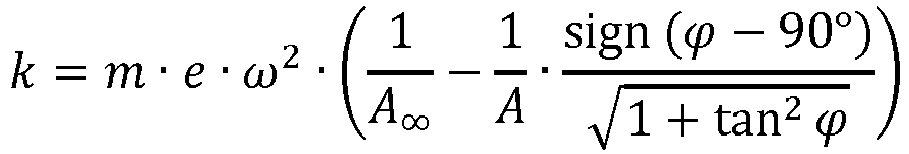
Mit dem Frequenzverhältnis β 
![]()
![]()
Auf diese Weise ist es möglich, laufend die zustandsabhängige Bodensteifigkeit und die dämpfende Wirkung des Bodens 17 während des Eindringens des Tiefenrüttlers 2 in den Boden beziehungsweise während des Verdichtungsprozesses zu ermitteln.In this way, it is possible to continuously determine the condition-dependent soil rigidity and the damping effect of the
Es versteht sich, dass die Berechnung eines die Bodensteifigkeit repräsentierenden Kennwertes nicht auf die beschriebene Möglichkeit beschränkt ist, sondern, dass prinzipiell auch andere Berechnungsmethoden zur Bestimmung des Bodensteifigkeitskennwertes zum Einsatz kommen können.It goes without saying that the calculation of a characteristic value representing the soil stiffness is not limited to the described possibility, but that in principle other calculation methods can also be used to determine the ground stiffness value.
Als Grundlage zur Ermittlung der Bodensteifigkeit kann für das Rüttelverfahren mittels eines Tiefenrüttlers 2 das mechanische Modell eines harmonisch angeregten Feder-Dämpfer-Systems 22 mit herangezogen werden, wie es in
Mit zunehmender Verdichtung steigt die Schwingungsamplitude A des Tiefenrüttlers 2 leicht an, bis ein Amplitudenmaximum Amax bei Resonanz erreicht ist. Ab diesem Punkt liegt die Betriebsphase s3 Postresonanz vor. Es erfolgt eine weitere Erhöhung der Bodensteifigkeit k mit im Wesentlichen konstanter Steigung, solange der Boden 17 durch Kornumlagerung weiter verdichtet wird. Ist eine maximale Verdichtung erreicht, steigt die Bodensteifigkeit k(t) in einem Knick an, der hier als Punkt P eingezeichnet ist. Der zugehörige Bodensteifigkeits-Übergangswert k12, liegt zwischen einem ersten Bodensteifigkeitswert k1 mit kleinerer Steigung und einem größeren Bodensteifigkeitswert k2 mit größerer Steigung. Entsprechend dem Knick im Punkt P der Kurve k(t) steigt die Ableitung beziehungsweise Steigungsrate k' der Bodensteifigkeit hier sprunghaft an. Dieser Knickpunkt P markiert den Übergang vom Verdichten C1 durch Kornumlagerung hin zur Kornverspannung C2, die eine temporäre Steifigkeitserhöhung durch die momentan erhöhte Vertikalbelastung des Bodens 17 durch den Rüttler 2 verursacht. Diese temporäre Steifigkeitserhöhung des Bodens 17 führt zu einer deutlich größeren Steigung des berechneten Bodensteifigkeitskennwerts k ab diesem Übergangspunkt P. Nachfolgend steigt der Bodensteifigkeitskennwert k mit nahezu konstanter Steigung weiter an, bis ein "Überdrücken" in der Betriebsphase s4 erreicht wird. Im daran anschließenden Schritt s1 wird der Rüttler 2 wieder gehoben, so dass der Steifigkeitskennwert k wieder abfällt.With increasing compression, the vibration amplitude A of the
Es ist weiter erkennbar, dass der Vorlaufwinkel ϕ während des Verdichtens C langsam abfällt. Dabei liegt der Vorlaufwinkel ϕ bei beginnender Verdichtung knapp unter 180° und sinkt bis zum Erreichen des Übergangspunkts P auf etwa 120°. Ab dem Erreichen des Übergangs-Bodensteifigkeitswerts k12 fällt der Vorlaufwinkel ϕ stärker ab, bis auf etwa 90°, die im überdrückten Zustand anliegen. Beim erneuten Heben s1 steigt der Phasenwinkel wieder auf den Ausgangswert an.It can also be seen that the lead angle ϕ slowly drops during compression C. When the compression begins, the lead angle ϕ is just under 180 ° and drops to about 120 ° until the transition point P is reached. When the transition ground stiffness value k12 is reached, the lead angle ϕ drops more sharply, down to about 90 °, which are present in the overpressed state. When lifting s1 again, the phase angle increases again to the initial value.
Gemäß dem vorliegenden Verfahren ist vorgesehen, dass das Erreichen des Übergangs-Bodensteifigkeitswerts k12 beziehungsweise der sprunghafte Anstieg der Steigung des Bodensteifigkeitskennwerts k als Abbruchkriterium für das Beenden des Rüttelvorgangs in der jeweiligen Verdichtungstiefe verwendet wird. Hiermit wird ein besonders effizientes Verdichtungsverfahren erreicht, da einerseits eine zu geringe Verdichtung und andererseits ein zu langes Verweilen in einer Verdichtungsstufe ohne zusätzlichen Verdichtungserfolg vermieden werden.According to the present method, it is provided that reaching the transition soil stiffness value k12 or the sudden increase in the slope of the soil stiffness value k is used as a termination criterion for ending the shaking process in the respective compaction depth. A particularly efficient compression process is hereby achieved since, on the one hand, too little compression and, on the other hand, excessive dwelling in a compression stage are avoided without additional compression success.
- 22nd
- TiefenrüttlerDeep vibrator
- 33rd
- MassekörperMass body
- 44th
- RüttlergehäuseVibrator housing
- 55
- DrehantriebRotary drive
- 66
- Sensor / WinkelgeberSensor / angle encoder
- 77
- Kupplungcoupling
- 88th
- GestängeLinkage
- 99
- WasserspülungWater flushing
- 1010th
- WasserspülungWater flushing
- 1111
- Leitungmanagement
- 1212th
- Sensor / Wasserdruckgeber, WasserdurchflussmengenzählerSensor / water pressure transmitter, water flow meter
- 1313
- Sensor / BeschleunigungsaufnehmerSensor / accelerometer
- 1414
- Sensor / BeschleunigungsaufnehmerSensor / accelerometer
- 1515
- Spitzetop
- 1616
- SchwingwegSwing path
- 1717th
- Bodenground
- 1818th
- VerdichtungskörperCompaction body
- 1919th
- KraftsensorForce sensor
- 2020
- VerdichtungsrasterCompression grid
- 2121
- Sensor / BeschleunigungsaufnehmerSensor / accelerometer
- 2222
- Feder-Dämpfer-System mit modal mitschwingender BodenmasseSpring-damper system with modal oscillating floor mass
- 2323
- Sensor / WegaufnehmerSensor / displacement sensor
- AA
- Amplitudeamplitude
- AooAoo
- Amplitude bei unendlich hoher ErregerfrequenzAmplitude at an infinitely high excitation frequency
- BB
- DrehachseAxis of rotation
- C1C1
- Verdichtung, KornumlagerungCompaction, grain rearrangement
- C2C2
- KornverspannungGrain tension
- cc
- DämpfungskoeffizientDamping coefficient
- ee
- Exzenter der UnwuchtEccentric of unbalance
- EE
- Ebenelevel
- kk
- BodensteifigkeitskennwertSoil stiffness value
- k'k '
- BodensteifigkeitssteigerungsrateSoil stiffness increase rate
- s1, s2, s3s1, s2, s3
- BetriebsphasenOperating phases
- tt
- Zeittime
- TT
- Tiefedepth
- mm
- Masse der UnwuchtMass of unbalance
- MM
- modale Rüttlermassemodal vibrator mass
- ΔMΔM
- modale mitschwingende Bodenmassemodal resonating soil mass
- PP
- ÜbergangspunktTransition point
- VV
- VergrößerungsfaktorMagnification factor
- ββ
- FrequenzverhältnisFrequency ratio
- ϕϕ
- VorlaufwinkelLead angle
- ωω
- ErregerfrequenzExcitation frequency
Claims (15)
- Method for detecting and controlling compaction when compacting a soil by means of a depth vibrator, wherein the depth vibrator (2) has an unbalance (3) rotationally driveable in a vibrator housing (4) and at least one sensor (6, 12, 13, 14, 19), comprising the steps:penetrating the depth vibrator (2) into the soil (17) to a desired final depth (Tm);compacting the soil (17) by the depth vibrator (2) in compaction steps wherein, during compacting, the advance angle (ϕ) of the unbalance (3) and the vibration amplitude (A) of the depth vibrator (2) are determined for a respectively measured depth (T);during a compaction step, detecting a soil stiffness profile from soil stiffness values (k) determined over time (t) on the basis of at least the advance angle (ϕ) and the vibration amplitude (A);determining a first soil stiffness value (k1) and a second soil stiffness value (k2) from the soil stiffness profile, for which it applies that a rate of increase (k'2) of the second soil stiffness value (k2) exceeds a rate of increase (k'1) of the first soil stiffness value (k1) by a defined factor;calculating a transition soil stiffness value (k12) which is between said first soil stiffness value (k1) and said second soil stiffness value (k2);saving the transition soil stiffness value (k12) determined in the respective compaction step to the corresponding depth (T).
- Method according to claim 1,
characterized in
that compaction is terminated in a compaction step if the rate of increase (k'2) of the second soil stiffness value (k2) is greater than 1.5 times the rate of increase (k'1) of the first soil stiffness value (k1), in particular if it is greater than twice the rate of increase (k'1) of the first soil stiffness value (k1). - Method according to claim 1 or 2,
characterized in
that after completion of compaction in a compaction depth (T) the depth vibrator (2) is pulled to the next depth to be compacted in order to compact the soil in this next depth. - Method according to any of claims 1 to 3,
characterized in
that at least one acceleration sensor (13, 14) which measures accelerations of the depth vibrator (2) during compaction, and
a position sensor (6) which detects a signal representing the position of the unbalance (3) are provided at the depth vibrator (2). - Method according to any of claims 1 to 4,
characterized in
that a plurality of acceleration sensors (13, 14) are attached to the depth vibrator (2) in different planes (E13, E14). - Method according to any of claims 1 to 5,
characterized in
that the soil stiffness value (k) representing the soil stiffness of the soil (17) is determined taking into account a modal resonating soil mass (ΔM). - Method according to claim 6,
characterized in
that the modal resonating soil mass (ΔM) is determined based on the unbalance (m · e), the vibration amplitude (A) and the mass (M) of the depth vibrator, in particular at least approximately according the formula:
- Method according to any of claims 1 to 7,
characterized in
that the soil stiffness value (k) representing the soil stiffness of the soil (17) is determined on the basis of the measured amplitude (A) and a reference amplitude (Aoo), wherein in particular the amplitude of the vibrator at any excitation frequency (ω) while free oscillation is used as the reference amplitude. - Method according to any of claims 1 to 8,
characterized in
that the soil stiffness value (k) representing the soil stiffness of the soil (17) is calculated taking into account the instantaneous amplification factor (V) of the measured amplitude (A) to the reference amplitude (Aoo), in particular according to the formula: - V is the amplification factor,- A is the vibration amplitude of the depth vibrator during compaction,- Aoo is the vibration amplitude of the depth vibrator while free oscillation and/or with an excitation frequency towards infinity,- M is the mass of the depth vibrator,- ΔM is the modal resonating soil mass,- m is the unbalance mass,- e is the eccentricity of the rotating unbalance m relative to the rotary axis.
 - Method according to any of claims 1 to 9,
characterized in
that the advance angle (ϕ) of the unbalance (3) relative to the vibrator motion is set to a value greater than 90° and less than 180°, in particular greater than 100° and less than 170°. - Method according to any of claims 1 to 10,
characterized in
that the soil stiffness value (k) representing the soil stiffness of the soil (17) is determined at least approximately according to the formula: - A is the vibration amplitude of the depth vibrator during compaction,- Aoo is the vibration amplitude of the depth vibrator while free oscillation and/or with an excitation frequency towards infinity,- m is the unbalance mass,- e is the eccentricity of the rotating unbalance m relative to the axis of rotation,- ω is the angular frequency of the rotating unbalance, and- ϕ is the phase advance of the rotating unbalance m relative to motion of the mass M of the depth vibrator.
 - Method for improving a ground by a depth vibrator, comprising the steps:producing a first compaction body (18), wherein the depth vibrator (2) is inserted into the soil (17) to a desired final depth (Tm), andafter reaching the final depth (Tm) the depth vibrator (2) is vibratingly pulled out of the soil (17) in vibration intervals of a defined amount (ΔT) in each case in order to compact the ground (17) step by step in depth sections,characterized in that, during vibrating in the respective compaction depth, the method according to any one of claims 1 to 11 is carried out.
- Method according to claim 12,
characterized in
that the soil stiffness profile derived from the transition soil stiffness values (k12) determined over the depth (T) is used to control the production of at least one further compaction body. - Method according to claim 13,
characterized in
that the vibration method is controlled taking into account the transition soil stiffness values (k12) in such a way that in a respective compaction depth (Tm, Tm-1, ... T2, T1) compaction is terminated when the transition soil stiffness value (k12) associated with the respective compaction depth is at least reached. - Method according to any of claims 12 to 14,
characterized in
that the determined soil stiffness profile is used for grid optimization of a grid of a plurality of compaction bodies (18) to be constructed.
Priority Applications (2)
| Application Number | Priority Date | Filing Date | Title |
|---|---|---|---|
| EP18153596.4A EP3517687B1 (en) | 2018-01-26 | 2018-01-26 | Method for compaction detection and control when compacting soil using deep vibrator |
| US16/256,457 US10385530B1 (en) | 2018-01-26 | 2019-01-24 | Method for compaction detection and control when compacting a soil with a deep vibrator |
Applications Claiming Priority (1)
| Application Number | Priority Date | Filing Date | Title |
|---|---|---|---|
| EP18153596.4A EP3517687B1 (en) | 2018-01-26 | 2018-01-26 | Method for compaction detection and control when compacting soil using deep vibrator |
Publications (2)
| Publication Number | Publication Date |
|---|---|
| EP3517687A1 EP3517687A1 (en) | 2019-07-31 |
| EP3517687B1 true EP3517687B1 (en) | 2020-08-05 |
Family
ID=61054213
Family Applications (1)
| Application Number | Title | Priority Date | Filing Date |
|---|---|---|---|
| EP18153596.4A Active EP3517687B1 (en) | 2018-01-26 | 2018-01-26 | Method for compaction detection and control when compacting soil using deep vibrator |
Country Status (2)
| Country | Link |
|---|---|
| US (1) | US10385530B1 (en) |
| EP (1) | EP3517687B1 (en) |
Families Citing this family (7)
| Publication number | Priority date | Publication date | Assignee | Title |
|---|---|---|---|---|
| CN111122087B (en) * | 2020-01-06 | 2021-03-23 | 山东大学 | System and method for measuring rigidity coefficient and viscous damping coefficient of compacted soil body |
| CN112052587B (en) * | 2020-09-02 | 2023-12-01 | 中国人民解放军陆军工程大学 | Compaction method of three-dimensional microscopic discrete body model of sand cushion |
| CN113358857B (en) * | 2021-04-30 | 2022-11-04 | 青海正旗工程检测有限公司 | Penetration type foundation soil compaction degree rapid detection equipment and method |
| CN113686729B (en) * | 2021-07-16 | 2024-01-30 | 太原市玉磊预拌混凝土有限公司 | Variable pressure internal vibration close packing density measuring method |
| CN114134879A (en) * | 2021-12-02 | 2022-03-04 | 成都雅蓝特科技有限公司 | Method for determining compaction current and vibration retention time of vibroflotation construction |
| CN114354757B (en) * | 2022-01-11 | 2022-11-01 | 中国铁道科学研究院集团有限公司铁道建筑研究所 | Roadbed compaction quality continuous detection system and method based on damping ratio |
| CN116340703B (en) * | 2023-04-04 | 2023-08-29 | 山东省地震工程研究院 | Soil sample parameter measurement method and system based on data |
Family Cites Families (15)
| Publication number | Priority date | Publication date | Assignee | Title |
|---|---|---|---|---|
| DE2133561B2 (en) * | 1971-07-06 | 1973-05-17 | Bauer, Karlheinz, Dr Ing , 8898 Schrobenhausen | DEEP RUETTLER FOR COMPACTING THE SOIL AND MAKING DRILLING HOLES IN THE SOIL |
| SE456507B (en) * | 1984-11-12 | 1988-10-10 | Pieux Armes Int | PROCEDURE AND DEVICE FOR MIDDLE VIBRATIONS PACKING AN EARTH STORE |
| DE4228542C1 (en) * | 1992-08-27 | 1994-05-11 | Keller Grundbau Gmbh | Method and device for compacting landfills using deep vibrations |
| US6244102B1 (en) * | 1998-09-18 | 2001-06-12 | Dynasens Ltd. | Method and system for examination and optimal compaction of soil enbankments |
| DE19859962C2 (en) * | 1998-12-29 | 2001-07-12 | Keller Grundbau Gmbh | Method and device for improving a building ground while determining the degree of compaction |
| DE19928692C1 (en) | 1999-06-23 | 2000-11-30 | Bauer Spezialtiefbau | On-line ground compaction control method uses detected sensor values for calculating system dynamic characteristics and actual ground loading for control of vibratory compactor |
| WO2001096669A1 (en) * | 2000-06-15 | 2001-12-20 | Geotechnical Reinforcement Company, Inc. | Lateral displacement pier and method of installing the same |
| DE10146342B4 (en) | 2001-09-20 | 2005-12-08 | Keller Grundbau Gmbh | Method for determining the storage density |
| EP1516961B1 (en) | 2003-09-19 | 2013-12-25 | Ammann Aufbereitung AG | Method for determining soil rigidity and soil compaction device |
| FR2941714B1 (en) * | 2009-01-30 | 2015-01-02 | Cie Du Sol | VIBRATOR DEVICE WITH HYDRAULIC MOTORIZATION FOR VIBRO COMPACT MACHINE. |
| EP2737132B1 (en) | 2011-06-15 | 2016-03-02 | Alexander Degen | Method for ground probing |
| DE102014019139A1 (en) * | 2014-12-23 | 2016-06-23 | Rsm Grundbau Gmbh + Willi Meyer Bauunternehmen Gmbh In Gbr | Deep vibrator with variable imbalance |
| US9702108B2 (en) * | 2015-05-28 | 2017-07-11 | JAFEC USA, Inc. | Direct power compaction method |
| DE202016107232U1 (en) * | 2016-12-21 | 2017-03-01 | BUG Dienstleistungen GmbH & Co. KG | Compacting plant for the compaction of compactible soils using a carrier device |
| EP3450631B1 (en) * | 2017-09-05 | 2019-12-04 | Keller Holding GmbH | Deep vibration apparatus with an adjustable unbalance mass body |
-
2018
- 2018-01-26 EP EP18153596.4A patent/EP3517687B1/en active Active
-
2019
- 2019-01-24 US US16/256,457 patent/US10385530B1/en active Active
Non-Patent Citations (1)
| Title |
|---|
| None * |
Also Published As
| Publication number | Publication date |
|---|---|
| EP3517687A1 (en) | 2019-07-31 |
| US10385530B1 (en) | 2019-08-20 |
| US20190234035A1 (en) | 2019-08-01 |
Similar Documents
| Publication | Publication Date | Title |
|---|---|---|
| EP3517687B1 (en) | Method for compaction detection and control when compacting soil using deep vibrator | |
| DE102017006844B4 (en) | Soil compactor and method for determining substrate properties by means of a soil compactor | |
| EP1516961B1 (en) | Method for determining soil rigidity and soil compaction device | |
| EP2627826B1 (en) | Method for determinig the rigidity and/or the damping of the region of a solidity | |
| DE102006008266B4 (en) | Method and device for measuring soil parameters by means of compaction machines | |
| DE102010060843B4 (en) | Method and device for measuring soil parameters by means of compaction machines | |
| EP3176324B1 (en) | Method for determining the compaction of a substrate | |
| DE3308476C2 (en) | ||
| DE112019003051T5 (en) | METHOD OF CONTROLLING THE OPERATION OF A VIBRATING ROLLER | |
| EP3981919B1 (en) | Method for providing information related to the compression state of a soil when performing a compaction process using a soil compressor | |
| DE10019806A1 (en) | Soil compacting device with vibration detection | |
| DE60303303T2 (en) | FALL WEIGHT COMPRESSION | |
| DE19859962C2 (en) | Method and device for improving a building ground while determining the degree of compaction | |
| WO1996007882A1 (en) | Process and device for testing vehicle shock absorbers | |
| EP2737132B1 (en) | Method for ground probing | |
| EP3109365B1 (en) | Method for controlling a vibration rammer | |
| DE19928692C1 (en) | On-line ground compaction control method uses detected sensor values for calculating system dynamic characteristics and actual ground loading for control of vibratory compactor | |
| EP1295994B1 (en) | Method to determine the degree of compaction of a foundation | |
| EP3315668B1 (en) | Method and system for the compaction of a soil | |
| DE112017008229T5 (en) | CONTROL OF COMPACTION OF A SUBSTRATE BY A SURFACE COMPACTION DEVICE |
Legal Events
| Date | Code | Title | Description |
|---|---|---|---|
| PUAI | Public reference made under article 153(3) epc to a published international application that has entered the european phase |
Free format text: ORIGINAL CODE: 0009012 |
|
| STAA | Information on the status of an ep patent application or granted ep patent |
Free format text: STATUS: THE APPLICATION HAS BEEN PUBLISHED |
|
| AK | Designated contracting states |
Kind code of ref document: A1 Designated state(s): AL AT BE BG CH CY CZ DE DK EE ES FI FR GB GR HR HU IE IS IT LI LT LU LV MC MK MT NL NO PL PT RO RS SE SI SK SM TR |
|
| AX | Request for extension of the european patent |
Extension state: BA ME |
|
| STAA | Information on the status of an ep patent application or granted ep patent |
Free format text: STATUS: REQUEST FOR EXAMINATION WAS MADE |
|
| 17P | Request for examination filed |
Effective date: 20190930 |
|
| RBV | Designated contracting states (corrected) |
Designated state(s): AL AT BE BG CH CY CZ DE DK EE ES FI FR GB GR HR HU IE IS IT LI LT LU LV MC MK MT NL NO PL PT RO RS SE SI SK SM TR |
|
| GRAP | Despatch of communication of intention to grant a patent |
Free format text: ORIGINAL CODE: EPIDOSNIGR1 |
|
| STAA | Information on the status of an ep patent application or granted ep patent |
Free format text: STATUS: GRANT OF PATENT IS INTENDED |
|
| RIC1 | Information provided on ipc code assigned before grant |
Ipc: E02D 3/054 20060101ALI20200127BHEP Ipc: E02D 1/02 20060101AFI20200127BHEP Ipc: E02D 7/18 20060101ALI20200127BHEP |
|
| INTG | Intention to grant announced |
Effective date: 20200228 |
|
| GRAS | Grant fee paid |
Free format text: ORIGINAL CODE: EPIDOSNIGR3 |
|
| GRAA | (expected) grant |
Free format text: ORIGINAL CODE: 0009210 |
|
| STAA | Information on the status of an ep patent application or granted ep patent |
Free format text: STATUS: THE PATENT HAS BEEN GRANTED |
|
| AK | Designated contracting states |
Kind code of ref document: B1 Designated state(s): AL AT BE BG CH CY CZ DE DK EE ES FI FR GB GR HR HU IE IS IT LI LT LU LV MC MK MT NL NO PL PT RO RS SE SI SK SM TR |
|
| REG | Reference to a national code |
Ref country code: GB Ref legal event code: FG4D Free format text: NOT ENGLISH |
|
| REG | Reference to a national code |
Ref country code: CH Ref legal event code: EP |
|
| REG | Reference to a national code |
Ref country code: AT Ref legal event code: REF Ref document number: 1298871 Country of ref document: AT Kind code of ref document: T Effective date: 20200815 |
|
| REG | Reference to a national code |
Ref country code: DE Ref legal event code: R096 Ref document number: 502018002040 Country of ref document: DE |
|
| REG | Reference to a national code |
Ref country code: IE Ref legal event code: FG4D Free format text: LANGUAGE OF EP DOCUMENT: GERMAN |
|
| REG | Reference to a national code |
Ref country code: LT Ref legal event code: MG4D |
|
| REG | Reference to a national code |
Ref country code: NL Ref legal event code: MP Effective date: 20200805 |
|
| PG25 | Lapsed in a contracting state [announced via postgrant information from national office to epo] |
Ref country code: ES Free format text: LAPSE BECAUSE OF FAILURE TO SUBMIT A TRANSLATION OF THE DESCRIPTION OR TO PAY THE FEE WITHIN THE PRESCRIBED TIME-LIMIT Effective date: 20200805 Ref country code: BG Free format text: LAPSE BECAUSE OF FAILURE TO SUBMIT A TRANSLATION OF THE DESCRIPTION OR TO PAY THE FEE WITHIN THE PRESCRIBED TIME-LIMIT Effective date: 20201105 Ref country code: SE Free format text: LAPSE BECAUSE OF FAILURE TO SUBMIT A TRANSLATION OF THE DESCRIPTION OR TO PAY THE FEE WITHIN THE PRESCRIBED TIME-LIMIT Effective date: 20200805 Ref country code: LT Free format text: LAPSE BECAUSE OF FAILURE TO SUBMIT A TRANSLATION OF THE DESCRIPTION OR TO PAY THE FEE WITHIN THE PRESCRIBED TIME-LIMIT Effective date: 20200805 Ref country code: HR Free format text: LAPSE BECAUSE OF FAILURE TO SUBMIT A TRANSLATION OF THE DESCRIPTION OR TO PAY THE FEE WITHIN THE PRESCRIBED TIME-LIMIT Effective date: 20200805 Ref country code: NO Free format text: LAPSE BECAUSE OF FAILURE TO SUBMIT A TRANSLATION OF THE DESCRIPTION OR TO PAY THE FEE WITHIN THE PRESCRIBED TIME-LIMIT Effective date: 20201105 Ref country code: FI Free format text: LAPSE BECAUSE OF FAILURE TO SUBMIT A TRANSLATION OF THE DESCRIPTION OR TO PAY THE FEE WITHIN THE PRESCRIBED TIME-LIMIT Effective date: 20200805 Ref country code: GR Free format text: LAPSE BECAUSE OF FAILURE TO SUBMIT A TRANSLATION OF THE DESCRIPTION OR TO PAY THE FEE WITHIN THE PRESCRIBED TIME-LIMIT Effective date: 20201106 Ref country code: PT Free format text: LAPSE BECAUSE OF FAILURE TO SUBMIT A TRANSLATION OF THE DESCRIPTION OR TO PAY THE FEE WITHIN THE PRESCRIBED TIME-LIMIT Effective date: 20201207 |
|
| PG25 | Lapsed in a contracting state [announced via postgrant information from national office to epo] |
Ref country code: IS Free format text: LAPSE BECAUSE OF FAILURE TO SUBMIT A TRANSLATION OF THE DESCRIPTION OR TO PAY THE FEE WITHIN THE PRESCRIBED TIME-LIMIT Effective date: 20201205 Ref country code: LV Free format text: LAPSE BECAUSE OF FAILURE TO SUBMIT A TRANSLATION OF THE DESCRIPTION OR TO PAY THE FEE WITHIN THE PRESCRIBED TIME-LIMIT Effective date: 20200805 Ref country code: NL Free format text: LAPSE BECAUSE OF FAILURE TO SUBMIT A TRANSLATION OF THE DESCRIPTION OR TO PAY THE FEE WITHIN THE PRESCRIBED TIME-LIMIT Effective date: 20200805 Ref country code: RS Free format text: LAPSE BECAUSE OF FAILURE TO SUBMIT A TRANSLATION OF THE DESCRIPTION OR TO PAY THE FEE WITHIN THE PRESCRIBED TIME-LIMIT Effective date: 20200805 Ref country code: PL Free format text: LAPSE BECAUSE OF FAILURE TO SUBMIT A TRANSLATION OF THE DESCRIPTION OR TO PAY THE FEE WITHIN THE PRESCRIBED TIME-LIMIT Effective date: 20200805 |
|
| PG25 | Lapsed in a contracting state [announced via postgrant information from national office to epo] |
Ref country code: SM Free format text: LAPSE BECAUSE OF FAILURE TO SUBMIT A TRANSLATION OF THE DESCRIPTION OR TO PAY THE FEE WITHIN THE PRESCRIBED TIME-LIMIT Effective date: 20200805 Ref country code: CZ Free format text: LAPSE BECAUSE OF FAILURE TO SUBMIT A TRANSLATION OF THE DESCRIPTION OR TO PAY THE FEE WITHIN THE PRESCRIBED TIME-LIMIT Effective date: 20200805 Ref country code: DK Free format text: LAPSE BECAUSE OF FAILURE TO SUBMIT A TRANSLATION OF THE DESCRIPTION OR TO PAY THE FEE WITHIN THE PRESCRIBED TIME-LIMIT Effective date: 20200805 Ref country code: RO Free format text: LAPSE BECAUSE OF FAILURE TO SUBMIT A TRANSLATION OF THE DESCRIPTION OR TO PAY THE FEE WITHIN THE PRESCRIBED TIME-LIMIT Effective date: 20200805 Ref country code: EE Free format text: LAPSE BECAUSE OF FAILURE TO SUBMIT A TRANSLATION OF THE DESCRIPTION OR TO PAY THE FEE WITHIN THE PRESCRIBED TIME-LIMIT Effective date: 20200805 |
|
| REG | Reference to a national code |
Ref country code: DE Ref legal event code: R097 Ref document number: 502018002040 Country of ref document: DE |
|
| PG25 | Lapsed in a contracting state [announced via postgrant information from national office to epo] |
Ref country code: AL Free format text: LAPSE BECAUSE OF FAILURE TO SUBMIT A TRANSLATION OF THE DESCRIPTION OR TO PAY THE FEE WITHIN THE PRESCRIBED TIME-LIMIT Effective date: 20200805 |
|
| PLBE | No opposition filed within time limit |
Free format text: ORIGINAL CODE: 0009261 |
|
| STAA | Information on the status of an ep patent application or granted ep patent |
Free format text: STATUS: NO OPPOSITION FILED WITHIN TIME LIMIT |
|
| PG25 | Lapsed in a contracting state [announced via postgrant information from national office to epo] |
Ref country code: SK Free format text: LAPSE BECAUSE OF FAILURE TO SUBMIT A TRANSLATION OF THE DESCRIPTION OR TO PAY THE FEE WITHIN THE PRESCRIBED TIME-LIMIT Effective date: 20200805 |
|
| 26N | No opposition filed |
Effective date: 20210507 |
|
| PG25 | Lapsed in a contracting state [announced via postgrant information from national office to epo] |
Ref country code: IT Free format text: LAPSE BECAUSE OF FAILURE TO SUBMIT A TRANSLATION OF THE DESCRIPTION OR TO PAY THE FEE WITHIN THE PRESCRIBED TIME-LIMIT Effective date: 20200805 |
|
| PG25 | Lapsed in a contracting state [announced via postgrant information from national office to epo] |
Ref country code: SI Free format text: LAPSE BECAUSE OF FAILURE TO SUBMIT A TRANSLATION OF THE DESCRIPTION OR TO PAY THE FEE WITHIN THE PRESCRIBED TIME-LIMIT Effective date: 20200805 Ref country code: MC Free format text: LAPSE BECAUSE OF FAILURE TO SUBMIT A TRANSLATION OF THE DESCRIPTION OR TO PAY THE FEE WITHIN THE PRESCRIBED TIME-LIMIT Effective date: 20200805 |
|
| REG | Reference to a national code |
Ref country code: CH Ref legal event code: PL |
|
| PG25 | Lapsed in a contracting state [announced via postgrant information from national office to epo] |
Ref country code: LU Free format text: LAPSE BECAUSE OF NON-PAYMENT OF DUE FEES Effective date: 20210126 |
|
| REG | Reference to a national code |
Ref country code: BE Ref legal event code: MM Effective date: 20210131 |
|
| PG25 | Lapsed in a contracting state [announced via postgrant information from national office to epo] |
Ref country code: LI Free format text: LAPSE BECAUSE OF NON-PAYMENT OF DUE FEES Effective date: 20210131 Ref country code: CH Free format text: LAPSE BECAUSE OF NON-PAYMENT OF DUE FEES Effective date: 20210131 |
|
| PG25 | Lapsed in a contracting state [announced via postgrant information from national office to epo] |
Ref country code: IE Free format text: LAPSE BECAUSE OF NON-PAYMENT OF DUE FEES Effective date: 20210126 Ref country code: CH Free format text: LAPSE BECAUSE OF NON-PAYMENT OF DUE FEES Effective date: 20210131 Ref country code: LI Free format text: LAPSE BECAUSE OF NON-PAYMENT OF DUE FEES Effective date: 20210131 |
|
| PGRI | Patent reinstated in contracting state [announced from national office to epo] |
Ref country code: CH Effective date: 20211028 Ref country code: LI Effective date: 20211028 |
|
| PG25 | Lapsed in a contracting state [announced via postgrant information from national office to epo] |
Ref country code: BE Free format text: LAPSE BECAUSE OF NON-PAYMENT OF DUE FEES Effective date: 20210131 |
|
| PGFP | Annual fee paid to national office [announced via postgrant information from national office to epo] |
Ref country code: FR Payment date: 20230109 Year of fee payment: 6 Ref country code: CH Payment date: 20230116 Year of fee payment: 6 Ref country code: AT Payment date: 20230105 Year of fee payment: 6 |
|
| PGFP | Annual fee paid to national office [announced via postgrant information from national office to epo] |
Ref country code: GB Payment date: 20230127 Year of fee payment: 6 Ref country code: DE Payment date: 20230106 Year of fee payment: 6 |
|
| PG25 | Lapsed in a contracting state [announced via postgrant information from national office to epo] |
Ref country code: CY Free format text: LAPSE BECAUSE OF FAILURE TO SUBMIT A TRANSLATION OF THE DESCRIPTION OR TO PAY THE FEE WITHIN THE PRESCRIBED TIME-LIMIT Effective date: 20200805 |
|
| PG25 | Lapsed in a contracting state [announced via postgrant information from national office to epo] |
Ref country code: HU Free format text: LAPSE BECAUSE OF FAILURE TO SUBMIT A TRANSLATION OF THE DESCRIPTION OR TO PAY THE FEE WITHIN THE PRESCRIBED TIME-LIMIT; INVALID AB INITIO Effective date: 20180126 |