EP1516961B1 - Method for determining soil rigidity and soil compaction device - Google Patents
Method for determining soil rigidity and soil compaction device Download PDFInfo
- Publication number
- EP1516961B1 EP1516961B1 EP03405688.7A EP03405688A EP1516961B1 EP 1516961 B1 EP1516961 B1 EP 1516961B1 EP 03405688 A EP03405688 A EP 03405688A EP 1516961 B1 EP1516961 B1 EP 1516961B1
- Authority
- EP
- European Patent Office
- Prior art keywords
- soil
- frequency
- compaction
- vibration
- sub
- Prior art date
- Legal status (The legal status is an assumption and is not a legal conclusion. Google has not performed a legal analysis and makes no representation as to the accuracy of the status listed.)
- Expired - Lifetime
Links
- 239000002689 soil Substances 0.000 title claims description 123
- 238000005056 compaction Methods 0.000 title claims description 89
- 238000000034 method Methods 0.000 title claims description 15
- 230000005284 excitation Effects 0.000 claims description 34
- 230000033001 locomotion Effects 0.000 claims description 25
- 230000009471 action Effects 0.000 claims description 13
- 238000005259 measurement Methods 0.000 claims description 6
- 238000011156 evaluation Methods 0.000 claims description 5
- 230000002829 reductive effect Effects 0.000 claims description 2
- 230000035945 sensitivity Effects 0.000 claims 1
- 230000010355 oscillation Effects 0.000 description 23
- 230000000739 chaotic effect Effects 0.000 description 22
- 238000013016 damping Methods 0.000 description 18
- 230000009191 jumping Effects 0.000 description 16
- 230000001133 acceleration Effects 0.000 description 14
- 230000009021 linear effect Effects 0.000 description 14
- 230000003068 static effect Effects 0.000 description 8
- 238000004364 calculation method Methods 0.000 description 7
- 238000005291 chaos (dynamical) Methods 0.000 description 6
- 230000006835 compression Effects 0.000 description 6
- 238000007906 compression Methods 0.000 description 6
- 230000000737 periodic effect Effects 0.000 description 6
- 238000001228 spectrum Methods 0.000 description 6
- 238000010586 diagram Methods 0.000 description 5
- 238000004088 simulation Methods 0.000 description 5
- 238000006243 chemical reaction Methods 0.000 description 4
- 230000010354 integration Effects 0.000 description 4
- 238000004458 analytical method Methods 0.000 description 3
- 230000009022 nonlinear effect Effects 0.000 description 3
- 238000010606 normalization Methods 0.000 description 3
- 230000002123 temporal effect Effects 0.000 description 3
- 230000009466 transformation Effects 0.000 description 3
- 238000012935 Averaging Methods 0.000 description 2
- 230000008859 change Effects 0.000 description 2
- 238000013461 design Methods 0.000 description 2
- 239000000203 mixture Substances 0.000 description 2
- 238000005096 rolling process Methods 0.000 description 2
- 230000007704 transition Effects 0.000 description 2
- 230000001960 triggered effect Effects 0.000 description 2
- PEDCQBHIVMGVHV-UHFFFAOYSA-N Glycerine Chemical compound OCC(O)CO PEDCQBHIVMGVHV-UHFFFAOYSA-N 0.000 description 1
- 241001289717 Hypolimnas Species 0.000 description 1
- 230000003321 amplification Effects 0.000 description 1
- 230000037007 arousal Effects 0.000 description 1
- 239000010426 asphalt Substances 0.000 description 1
- 230000002238 attenuated effect Effects 0.000 description 1
- 230000005540 biological transmission Effects 0.000 description 1
- 239000004566 building material Substances 0.000 description 1
- 230000000052 comparative effect Effects 0.000 description 1
- 230000003247 decreasing effect Effects 0.000 description 1
- 238000000280 densification Methods 0.000 description 1
- 230000001419 dependent effect Effects 0.000 description 1
- 238000001514 detection method Methods 0.000 description 1
- 238000011161 development Methods 0.000 description 1
- 238000006073 displacement reaction Methods 0.000 description 1
- 230000000694 effects Effects 0.000 description 1
- 238000005516 engineering process Methods 0.000 description 1
- 230000005279 excitation period Effects 0.000 description 1
- 238000013467 fragmentation Methods 0.000 description 1
- 238000006062 fragmentation reaction Methods 0.000 description 1
- 238000007689 inspection Methods 0.000 description 1
- 238000009413 insulation Methods 0.000 description 1
- 238000011835 investigation Methods 0.000 description 1
- 238000002955 isolation Methods 0.000 description 1
- 239000010410 layer Substances 0.000 description 1
- 238000013507 mapping Methods 0.000 description 1
- 239000000463 material Substances 0.000 description 1
- 238000012544 monitoring process Methods 0.000 description 1
- 238000005312 nonlinear dynamic Methods 0.000 description 1
- 238000003199 nucleic acid amplification method Methods 0.000 description 1
- 230000036961 partial effect Effects 0.000 description 1
- 230000002265 prevention Effects 0.000 description 1
- 230000004044 response Effects 0.000 description 1
- 238000012552 review Methods 0.000 description 1
- 239000000523 sample Substances 0.000 description 1
- 239000002904 solvent Substances 0.000 description 1
- 230000003595 spectral effect Effects 0.000 description 1
- 230000000638 stimulation Effects 0.000 description 1
- 239000002344 surface layer Substances 0.000 description 1
- 239000000725 suspension Substances 0.000 description 1
- 238000012360 testing method Methods 0.000 description 1
- 238000005303 weighing Methods 0.000 description 1
Images


Classifications
-
- E—FIXED CONSTRUCTIONS
- E01—CONSTRUCTION OF ROADS, RAILWAYS, OR BRIDGES
- E01C—CONSTRUCTION OF, OR SURFACES FOR, ROADS, SPORTS GROUNDS, OR THE LIKE; MACHINES OR AUXILIARY TOOLS FOR CONSTRUCTION OR REPAIR
- E01C19/00—Machines, tools or auxiliary devices for preparing or distributing paving materials, for working the placed materials, or for forming, consolidating, or finishing the paving
- E01C19/22—Machines, tools or auxiliary devices for preparing or distributing paving materials, for working the placed materials, or for forming, consolidating, or finishing the paving for consolidating or finishing laid-down unset materials
- E01C19/23—Rollers therefor; Such rollers usable also for compacting soil
- E01C19/28—Vibrated rollers or rollers subjected to impacts, e.g. hammering blows
- E01C19/288—Vibrated rollers or rollers subjected to impacts, e.g. hammering blows adapted for monitoring characteristics of the material being compacted, e.g. indicating resonant frequency, measuring degree of compaction, by measuring values, detectable on the roller; using detected values to control operation of the roller, e.g. automatic adjustment of vibration responsive to such measurements
-
- E—FIXED CONSTRUCTIONS
- E02—HYDRAULIC ENGINEERING; FOUNDATIONS; SOIL SHIFTING
- E02D—FOUNDATIONS; EXCAVATIONS; EMBANKMENTS; UNDERGROUND OR UNDERWATER STRUCTURES
- E02D3/00—Improving or preserving soil or rock, e.g. preserving permafrost soil
- E02D3/02—Improving by compacting
- E02D3/046—Improving by compacting by tamping or vibrating, e.g. with auxiliary watering of the soil
Definitions
- the invention relates to a method for determining a mass for the soil stiffness (degree of compaction) of a compacted or compacted soil area according to the preamble of patent claim 1, as well as a soil compacting device according to the preamble of patent claim 7.
- a compression should always be optimal, d. H. fastest and with the least expenditure of energy feasible when resonance of the soil compaction system occurred.
- the soil compacting system was formed of the soil to be compacted and the compacting device acting on it.
- the accelerometer measures a non-harmonic vibration.
- the excitation was increased or a stiffer and more elastic ground was reached, a periodicity of the oscillation occurred at half the frequency. This condition was considered stable. If the stimulation was increased even more, or if the ground was even stiffer, jumping of the bandage occurred. The measured quotient was significantly higher than mentioned above.
- the object of the invention is to compress a soil area to a predetermined or to a maximum of a machine design according to achievable soil stiffness, to determine the degree of compaction achieved and to provide a soil compaction device with which this optimal soil compaction is to make.
- a soil compaction with a predetermined or maximum possible soil stiffness is a ground contact unit acting on the floor area of a soil compacting device moves over the latter. In this case acts on the ground contact unit a time periodically changing with at least one action frequency force.
- the vibrations of a vibration system consisting of the soil compacting device with the ground contact unit and the respective ground area, are determined.
- the vibration form of the vibration of the vibration system is recorded, and the soil rigidity (degree of compaction) is then determined from the vibration mode, from the engine parameters of the soil compacting device and from the timing of the soil compaction force.
- the subharmonics are determined, but also their amplitudes, which are set in relation to the amplitude of the action frequency.
- the maximum amplitude values will be used for this purpose.
- a sensor will be mounted on the ground contact unit next to a sensor for the subharmonics, which measures the temporal deflection in the direction of soil compaction.
- the temporal deflection of the excitation can also be measured; However, it can easily be determined from the instantaneous position of the imbalance or imbalances.
- the temporal position of the maximum amplitudes (excitation oscillation to the vibration of the ground contact unit) will be determined with a comparator unit.
- the excitation is preferably adjusted such that the maximum amplitude of the excitation by 90 ° to 180 °, preferably by 95 ° to 130 ° ahead of the maximum amplitude of the ground contact unit.
- An adjustment of the exciting force may be avoided when using e.g. be achieved by two imbalances, which rotate at the same rotational speed and the angular distance is changeable.
- the imbalances can be moved in the same direction or in opposite directions.
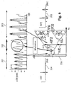
- FIG. 1 For this purpose, a compactor 1 with rear, rubber-tired wheels 3 and a front bandage 5 as a ground contact unit and a chassis 6 is shown. Based on this system, a one-sided bond between a bottom region 7 to be compacted (substructure) and the compactor 1 (compacting device) is the main reason for the occurrence of nonlinear effects. The one-sided binding is justified by the fact that between the compactor 1 and the bottom portion 7 compressive forces but no tensile forces can be transmitted.
- the compaction apparatus 1 When the maximum ground force values are exceeded, the compaction apparatus 1 periodically loses contact with the ground area 7 (subsurface). Additional non-linear elements of the soil properties, such as shear strain-controlled stiffness changes, can be neglected in comparison. Also, the superlinear spring characteristic of (rubber) damping elements 8 between the chassis 6 and ground contact unit 5 (bandage), or a superstructure 9 and an undercarriage 11 of a trench roller 12 explained later is of minor importance and does not significantly affect the calculation results of an analytical description. The same applies to a vibration plate 14 with a superstructure 15 and a lower carriage 17th
- a compacting device generally, as well as the compactor 1 in FIG. 1 , a ground contact unit (bandage 5, undercarriage 11 or 17 ) with a vibrating part, for example with a rotating imbalance 13 with a mass m d including an imbalance exciter.
- a static Auflastabout of the chassis 6 is based with a mass m f (static weight) via damping elements 8 (stiffness k G , damping c G ) from.
- the static weight m f together with the damping elements 8 , produces a point-point-excited vibration system which is tuned low (low natural frequency).
- the uppercarriage 9 or 15 or the chassis 6 acts in vibration mode with respect to the vibrations of the undercarriage 11 or 17 or the bandage 5 as a low-pass second order.
- the vibration energy transmitted into the chassis 6 or the superstructure 9 or 15 is minimized.
- the compacted or compacted bottom of the bottom region 7 is a building material for which, depending on the properties investigated, different models exist.
- simple spring-damper models (stiffness k B , damping c B ) are used.
- the spring properties take into account the contact zone between the soil compaction unit (bandage) and the elastic half-space (floor area).
- the ground stiffness k B is a static, frequency-independent variable. This property could be demonstrated in the present application in the field trial for homogeneous and layered soils.
- Equation (1) describes the associated motion differential equations for the degrees of freedom x d of the drum 5 and x f of the chassis 6 .
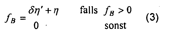
- a soil reaction force F B between the bandage 5 and the compacted or compacted bottom region 7 controls the nonlinearity of the unilateral bond.
- Vibratory plates ( FIG. 8 ) and rammers are basically the same considerations, taking into account the respective excitation principle result in analogous equations.
- a numerical simulation allows the calculation of the solutions of equations (1).
- the use of numerical solution algorithms is essential.
- analytical calculation methods such as the averaging method, very good approximate solutions and statements of a fundamental nature can be made for a bifurcation of the fundamental vibrations for linear and nonlinear oscillations.
- the averaging theory is described in Heatgg Roland (1998), “Nonlinear Vibrations in Dynamic Soil Compactors, Progress VDI, Series 4, VDI Verlag Dusseldorf.” This allows a good overall view about the occurring solutions.
- analytical methods are associated with a disproportionately high outlay.
- the coordinate system of equations (1) and (3) includes a static depression due to the dead weight (static load weight m f , swinging mass m d ).
- the static sinking has to be subtracted for comparison purposes in the simulation result.
- the initial conditions for the simulation are all set to "0". The results are given for the case of the steady state.
- a solvent solver is chosen "ode 45" (Dormand-Price) with a variable integration step size (maximum step size 0.1 s) in the time range from 0 s to 270 s.
- FIG. 3 is a comparison between a simulated and a measured case of a "strong jumping" of a compactor 1, here a compactor from Ammann AC 110 with 11 t total weight, shown.
- a very good agreement between measured and calculated vibration behavior of a bandage 5 can be seen.
- the measured data were recorded with an acceleration sensor mounted in the vertical direction on the non-rotating, oscillating part of the drum 5, the signal then amplified and analyzed using a program package, eg LabView / DIAdem®.
- an amplitude A 0 of 1 mm and a ground stiffness k B of 140 MN / m have been specified. If one measures the movement in a time range for the "jumping" of a compactor, an iterative calculation method can be used to determine the actual soil stiffness down to a tolerance. For this purpose, the machine parameters of the compacting device, the operating state and the time position of the imbalance or imbalances must be known.
- the practically measured and numerically simulated operating state of jumping of the pulley AC 110 with respect to the chaos theory represents a nonlinear system after the occurrence of the first period doubling.
- the compactors are thus among the technical systems that are fundamentally capable of chaotic behavior. Their dynamics can thus be described using the methods of nonlinear and chaotic vibrational theory. This opens up a large field of different analysis methods, which can be applied in theory and practice of compaction technology.
- F B is the force acting on the floor area; please refer FIG. 2 .
- phase space representation with x 1 ( t ) - x 2 ( t ), or x ( t ) - ⁇ ( t ) is derived.
- phase curves also referred to as orbitals
- orbitals are closed circles or ellipses in the case of linear, stationary and monofrequent oscillations.
- additional harmonics occur (periodic lifting of the bandage from the ground)
- the harmonics can be recognized as modulated periodicities. Only at period doublings, ie subharmonic oscillations such as "jumping", does the original circle mutate into closed curves that have intersections in the phase space representation.
- FIG. 5 illustrated phase curve.
- the left display shows the measured and the left display the calculated values. Again the agreement of the simulation with the data measured in practice is shown.
- FIG. 6 shows the measured, unmediated occurrence of jumping a roller (Ammann AC 110) during the transition of the machine from a very soft pad (tire) on an already compacted, hard sand-gravel mixture. With otherwise constant machine parameters, ground stiffness and damping are the variable system parameters.
- the performed FFT shows in FIG. 6 left, the linear, monofrequency vibration behavior on the tire, Pneu (soft bottom) 204; the subharmonic oscillation, which additionally occurs on a hard surface, has about twice the amplitude compared to the fundamental mode (right illustration in FIG. 6 If you measure with each unbalance rotation in an excellent position of the rotating eccentric the corresponding vibration amplitude, or the deformation value of the movement, this is always constant on the tire (harmonious), on the hard pad, however, the value alternates according to the additional subharmonic vibration component. Due to their periodicity, harmonics can not be detected in this type of signal acquisition.
- the measurement acquisition can in practice be triggered by the pulse of a Hall probe, which detects the zero crossing of the vibro wave.
- the branches produce a cascade of new vibrational components with each half the frequency of the previous lowest frequency of the spectrum. Since the first branching off from the fundamental oscillation with the frequency f, or period T, splits off, the frequency cascade f, f / 2, f / 4, f / 8 etc. is generated. Analogously to the fundamental oscillation, the subharmonic harmonics also generate it creates a frequency continuum in the low-frequency range of the signal spectrum. This is also a specific property of the chaotic system, in this case the vibrating roller.
- the system of the compactor is in a deterministic rather than a stochastic chaotic state. Since the parameters that cause the chaotic state are not all measurable (not fully observable), the operating state of the subharmonic vibrations can not be predicted for practical compaction.
- the operating behavior in practice is also characterized by many imponderables, the machine can slip away due to the strong contact loss to the ground, the load of the machine by the low-frequency vibrations is very high. Ongoing further bifurcations of the machine behavior (unexpected) can occur, which immediately result in heavy additional loads. High stresses also occur between the bandage and the floor; This leads to the undesirable loosening of near-surface layers and causes grain breakup.
- the subharmonic vibrations each represent a new state of motion of the machine
- relative measurements eg. B. for detecting the compaction state of the soil
- subharmonic oscillation on the reference inspection procedures such as the pressure plate test (DIN 18 196) be calibrated.
- the correlation basically changes with the occurrence of the jumping; only within the respective branching state of the movement exists a linear relationship of the measured value with the soil stiffness.
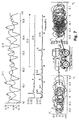
- the bifurcation occurs in the form of the period doubling scenario, the FIG. 7 or the FIG. 8 show this on the basis of the FFT spectrum for a trench roller or a vibrating plate.
- phase space of the motions of the upper and lower carriage of the vibrating plate and the trench roller show in comparison to the corresponding orbital of the compactor ( FIG. 5 ) significantly increase the complexity of the movements when the advanced period doubling scenario, or deterministic chaos, occurs.
- plates and rammers are devices weighing between 50 and 500 kg, it can be casually said that the smaller the device, the greater the vibration challenge.
- the ground stiffness k B achieved by a soil compaction device as determined by the soil compaction devices mentioned above can be dispensed with, as long as accurate (exact) ground stiffness values are desired and only an indication is given indicating whether soil rigidity increases or is already satisfactory on further traversal with the device Has achieved value, greatly simplified and thus inexpensive with the following in FIG. 10 shown measuring device 20 are made.
- Such a measuring device 20 for a Bodensteiftechniksrichtwert will be installed mainly in the already inexpensive vibrating plates.
- the vibrations of the undercarriage 17 are recorded with an acceleration sensor 21 , amplified by an amplifier 23 and integrated with an integrator 25 over a predetermined period of time.
- the integration is made from the acceleration value measured with the acceleration sensor 21 after two times Integration to get a way.
- the output signal of the integrator 25 is fed to a plurality of bandpass filters 27 .
- the bandpass filter is designed such that once the excitation frequency f, the first harmonic at twice the excitation frequency 2 ⁇ f, the first subharmonic with the half excitation frequency f / 2, the second subharmonic with a fourth excitation frequency f / 4 and the third subharmonic with a achtel excitation frequency f / 8 are transmitted to one output 29a to 29e .
- the measuring device has four quotient formers 31a to 31d for monitoring the frequencies 2 * f, f, f / 2, f / 4 and f / 8 .
- the output 29b (output signal to f) is connected as a divisor to all quotient formers 31a to 31d . All outputs are each connected to a quotient generator 31a to 31d .
- the output 29a (output signal to 2 * f) is connected as a dividend to the quotient generator 31a whose output signal (quotient) is applied to its output 33a .
- the output 33a is routed via a normalization circuit 35 to two lights 37a in a display panel 39 .
- the luminaires 37b do not light up even if they are repeatedly driven over with the vibrating plate, further compaction, be it due to the soil composition or the machine data of the vibrating plate used, is not possible. The same applies to the lights 37c and 37d .
- the maximum amplitude A (f) with the action frequency f is smaller than that A (f / 2) of the first subharmonic f / 2.
- the expected maximum amplitudes can be read analogously from the "fig tree scenario”.
- the soil stiffness k B degree of compaction
- the soil stiffness k B degree of compaction
- bandpass filter 27 a unit which performs a fast Fourier transformation (FFT) may also be used.
- FFT fast Fourier transformation
- the respective oscillation amplitude can also be determined within time windows. In this case, starting from the lowest position of the eccentric and the known rotational speed, the amplitude values for the first harmonic and corresponding subharmonics will be recorded, if they are present.
- FIG. 11 is a variant of the in FIG. 10 shown circuit shown.
- an acceleration sensor 42 designed analogously to the acceleration sensor 21 is arranged on the uppercarriage 15 of a vibration plate 14 .
- damping elements between the upper and lower chassis is a vibration damping.
- the output signals of the acceleration sensor 42 for the first harmonic 2f and the first and second subharmonic f / 2 and f / 4 are now not integrated in contrast to the circuit 20 and processed as acceleration signals after amplification by the amplifier 23 in a bandpass filter 41st
- the signals are usually high enough.
- the signal of the third subharmonic f / 8 is now, since it is usually small, integrated with an integrator 43 and analogous to in FIG. 10 processed. It does not have to be integrated until the third subharmonic f / 8 . It is also possible to integrate the second subharmonic f / 4 or the fourth subharmonic f / 16 (x: factor, x ⁇ 1-2).
- the sensor for receiving the waveform of the vibration system is arranged according to the above description on the undercarriage 11 or 17 or on the chassis 6 ; he but can also be arranged on the superstructure 9 and 15 respectively.
- vibration influences due to the damping elements, as outlined above, must be taken into account.
- the demonstration of the chaotic behavior of dynamically excited compaction devices places the vibration behavior patterns known from various investigations into a common context.
- the basis is the one-sided bond between soil (asphalt layer) and the oscillating part of the device.
- the increase in the vibration excitation and / or the increasing rigidity of the soil with increasing compression leads to the periodic lifting of the compactor from the ground.
- the resulting non-linearity increases with greater unbalance or increasing densification, which leads to the bifurcation of the movement behavior.
- the branching occurs suddenly and, depending on the type of machine, represents an undesirable or intended operating condition. Therefore, this is avoided in controlled rolls by reducing the vertical unbalance.
- the oscillating part enters the period doubling scenario, the movement behavior becomes chaotic.
Description
Die Erfindung betrifft ein Verfahren zur Ermittlung eines Masses für die Bodensteifigkeit (Verdichtungsgrad) eines verdichteten bzw. zu verdichtenden Bodenbereichs gemäss dem Oberbegriff des Patentanspruchs 1, sowie eine Bodenverdichtungsvorrichtung gemäss dem Oberbegriff des Patentanspruchs 7.The invention relates to a method for determining a mass for the soil stiffness (degree of compaction) of a compacted or compacted soil area according to the preamble of
In der Veröffentlichung von R. Anderegg, "Vibrationswalzen mit regelbaren Parametern und die FDVK", Straßen- und Tiefbau, Giesel Verlag für Publizität, Iserhagen, DE, Nr. 12. 1997, S. 11-17 wurde eine flächendeckende dynamische Verdichtungskontrolle (FDVK) beschrieben, welche zur Überwachung laufender und einer Nachprüfung abgeschlossener Verdichtungsarbeiten diente. Es wurden hauptsächlich Bandagenschwingungen in vertikaler Richtung berücksichtigt, wobei die Bandage und der verdichtete bzw. noch zu verdichtende Bodenbereich ein Schwingungssystem bildeten. Da die Bandage mit dem Boden nicht fest verbunden war, konnten lediglich zwischen Bodenbereich und Bandage Druck-, nicht aber Zugkräfte übertragen werden. Die Bodenreaktionskraft nahm deshalb nur positive Werte an. Die Bandage konnte vom Boden abheben. Durch den periodischen Kontaktverlust zwischen Bandage und Boden ergaben sich nichtlineare Effekte, welche zu Oberschwingungen führten. Bei einer weiteren Zunahme der Nichtlinearität konnte eine subharmonische Schwingung mit halber Anregungsfrequenz auftreten. Die Verdichtungsvorrichtung begann zu springen oder zu taumeln. Traten subharmonische Schwingungen auf, wurde zu deren Vermeidung vorgeschlagen, die Unwucht zu verkleinern, da insbesondere das Taumeln zu Kornzertrümmerungen im Untergrund führte und die Bauwerksoberfläche beschädigt wurde. Eine wachsende Eigenfrequenz des Systems Bandage /Bodenbereich dient als Mass für eine zunehmende Verdichtung.In the publication by R. Anderegg, "Vibratory rollers with controllable parameters and the FDVK", road and civil engineering, Giesel Verlag for publicity, Iserhagen, DE, No. 12. 1997, pp 11-17 was a nationwide dynamic compression control (FDVK ), which was used to monitor ongoing and a review of completed compaction work. Mainly bandage vibrations in the vertical direction were taken into account, whereby the bandage and the compacted or still to be compacted bottom area formed a vibration system. Since the bandage was not firmly connected to the ground, pressure could only be transmitted between the ground area and the bandage, but not tensile forces. The soil reaction force therefore only assumed positive values. The bandage was able to lift off the ground. The periodic loss of contact between the bandage and the ground resulted in non-linear effects, which led to harmonics. With a further increase in non-linearity, a subharmonic oscillation with half excitation frequency could occur. The compactor began to jump or stumble. If subharmonic vibrations occurred, it was suggested that they be avoided in order to reduce the imbalance, since the tumbling in particular led to fragmentation of the ground and damaged the building surface. A growing natural frequency of the system bandage / floor area serves as a measure of increasing compaction.
In der deutschen Offenlegungsschrift
In der
In der
- ➢ Auflastbetrieb: Die Vorrichtung bleibt in Bodenkontakt. Der Beschleunigungsaufnehmer misst nur die Umlauffrequenz der Unwucht (1 · f).
- ➢ Optimaler Betriebszustand: Die Bandage hebt periodisch vom Boden ab. Der Beschleunigungsaufnehmer misst Oberschwingungen (2 · f, 3 · f usw.) mit stark abnehmender maximaler Amplitude.
- ➢ Instabiler Zustand: Die ganze Bodenverdichtungsvorrichtung (Walze) fängt an zu springen. Es treten zu den Oberschwingungen Subharmonische (1/2 · f, 3/2 · f, 5/2 · f usw.) auf.
- ➢ Overload operation: The device remains in contact with the ground. The accelerometer measures only the rotational frequency of the imbalance (1 · f).
- ➢ Optimal operating condition: The bandage periodically lifts off the ground. The accelerometer measures harmonics (2 · f, 3 · f, etc.) with greatly decreasing maximum amplitude.
- ➢ Unstable condition: The whole soil compaction device (roller) starts to jump. Subharmonics (1/2 · f, 3/2 · f, 5/2 · f, etc.) occur for the harmonics.
Eine Verdichtung sollte immer dann optimal sein, d. h. am schnellsten und unter geringstem Energieaufwand vollziehbar, wenn Resonanz des Bodenverdichtungssystems auftrat. Das Bodenverdichtungssystem war aus dem zu verdichtenden Boden und der auf diesen einwirkenden Verdichtungseinrichtung gebildet.A compression should always be optimal, d. H. fastest and with the least expenditure of energy feasible when resonance of the soil compaction system occurred. The soil compacting system was formed of the soil to be compacted and the compacting device acting on it.
In der
In der
Bei einer nur geringen Anregung oder einem weichen Boden mass der Beschleunigungsmesser eine nicht harmonische Schwingung. Wurde die Anregung gesteigert oder war ein steiferer und elastischerer Boden erreicht, trat eine Periodizität der Schwingung mit halber Frequenz auf. Dieser Zustand wurde als noch stabil betrachtet. Wurde nun die Anregung noch mehr gesteigert oder war der Boden noch steifer, trat Springen der Bandage auf. Der gemessene Quotient war hier bedeutend höher als oben erwähnt.With only a slight excitation or a soft ground, the accelerometer measures a non-harmonic vibration. When the excitation was increased or a stiffer and more elastic ground was reached, a periodicity of the oscillation occurred at half the frequency. This condition was considered stable. If the stimulation was increased even more, or if the ground was even stiffer, jumping of the bandage occurred. The measured quotient was significantly higher than mentioned above.
In der
Aufgabe der Erfindung ist es, einen Bodenbereich auf eine vorgegebene oder auf eine entsprechend einer Maschinenauslegung maximal erreichbare Bodensteifigkeit zu verdichten, den erreichten Verdichtungsgrad zu ermitteln sowie eine Bodenverdichtungsvorrichtung zu schaffen, mit der diese optimale Bodenverdichtung vorzunehmen ist.The object of the invention is to compress a soil area to a predetermined or to a maximum of a machine design according to achievable soil stiffness, to determine the degree of compaction achieved and to provide a soil compaction device with which this optimal soil compaction is to make.
Die Lösung der Aufgabe erfolgt verfahrensmässig durch die Merkmale des Patentanspruchs 1 und Vorrichtungsmässig durch die Merkmale des Patentanspruchs 7. Um eine optimale Bodenverdichtung, d.h. eine Bodenverdichtung mit einer vorgegebenen bzw. maximal möglichen Bodensteifigkeit (Verdichtungsgrad) zu erreichen, wird eine auf den Bodenbereich einwirkende Bodenkontakteinheit einer Bodenverdichtungsvorrichtung über diesen bewegt. Auf die Bodenkontakteinheit wirkt hierbei eine zeitlich sich periodisch mit wenigstens einer Einwirkungsfrequenz ändernde Kraft ein. Die Schwingungen eines Schwingungssystems, bestehend aus der Bodenverdichtungsvorrichtung mit der Bodenkontakteinheit und dem jeweiligen Bodenbereich, werden ermittelt. Die Schwingungsform der Schwingung des Schwingungssystems wird aufgenommen und aus der Schwingungsform, aus den Maschinenparametern der Bodenverdichtungsvorrichtung und aus der zeitlichen Lage der einen Bodenverdichtungskraft wird dann die Bodensteifigkeit (Verdichtungsgrad) ermittelt.The object is achieved procedurally by the features of
Im Gegensatz zu den bekannten Bodenverdichtungsverfahren bzw. den bekannten Bodenverdichtungsvorrichtungen wird hier nicht versucht, Subharmonsiche zur Einwirkungsfrequenz zu eliminieren. Im Gegenteil, sie werden bewusst ausgewertet. Erfindungsgemäß wird nämlich von der Erkenntnis ausgegangen, wie in der Detailbeschreibung dargelegt ist, dass die Frequenzen der Subharmonischen einen erreichten Bodenverdichtungsgrad definieren. Je tiefer die Frequenz der tiefsten Subharmonischen ist, desto grösser ist der Bodenverdichtungsgrad, über den eine Bodenkontakteinheit einer Bodenverdichtungsvorrichtung bewegt wird.In contrast to the known soil compaction methods or the known soil compacting devices, no attempt is made here to eliminate subharmonic pertubation to the frequency of action. On the contrary, they are deliberately evaluated. In fact, according to the invention, it is based on the knowledge, as stated in the detailed description, that the frequencies of the subharmonics define an achieved degree of soil compaction. The lower the frequency of the deepest subharmonic, the greater the soil compaction level over which a ground contact unit of a soil compaction device is moved.
In einer besonderen Ausführungsvariante werden nicht nur die Subharmonischen ermittelt, sondern auch deren Amplituden, welche zur Amplitude der Einwirkungsfrequenz ins Verhältnis gesetzt werden. Vorzugsweise wird man die maximalen Amplitudenwerte hierzu verwenden. Es können aber auch Amplitudenwerte bei einer vorgegebenen Phasenlage verwendet werden. Wie aus einem unten beschriebenen Feigenbaum Szenario ersichtlich ist, ergibt diese Berücksichtigung neben der Ermittlung der Subharmonischen eine exaktere Bestimmung der erreichten bzw. vorhandenen Bodensteifigkeit.In a particular embodiment variant, not only the subharmonics are determined, but also their amplitudes, which are set in relation to the amplitude of the action frequency. Preferably, the maximum amplitude values will be used for this purpose. However, it is also possible to use amplitude values for a given phase position. As can be seen from a fig tree scenario described below, this consideration, in addition to the determination of the subharmonic results in a more accurate determination of the achieved or existing soil stiffness.
Man kann nun die Bodenkontakteinheit, welche mit dem zu verdichtenden bzw. bereits verdichteten Boden in Kontakt ist, mit einer einzigen Sinus-Schwingung in der Regel durch einen umlaufenden Exzenter oder durch zwei winkelmässig gegeneinander verstellbare Exzenter kraftmässig beaufschlagen. Es können aber auch mehrere Exzenter mit unterschiedlichen Umlauffrequenzen verwendet werden. Zu jeder dieser Frequenzen ergibt sich dann eine Reihe von Subharmonischen je nach erreichtem Bodenverdichtungsgrad. Werden mehrere "Grundfrequenzen" verwendet, kann eine detailliertere Aussage über die erreichte bzw. die zu messende Bodenverdichtung gemacht werden.Now you can force the ground contact unit, which is in contact with the compacted or already compacted soil, with a single sinusoidal oscillation usually by a rotating eccentric or by two angularly mutually adjustable eccentric. However, it is also possible to use a plurality of eccentrics with different circulating frequencies. For each of these frequencies, a series of subharmonics results depending on the degree of soil compaction achieved. If several "fundamental frequencies" are used, a more detailed statement can be made about the achieved or measured soil compaction.
Vorzugsweise wird man jedoch die Einwirkungsfrequenz auf die Bodenkontakteinheit einstellbar wählen. Bei einer einstellbaren Frequenz kann nämlich eine Resonanz des Schwingungssystems, bestehend aus Bodenkontakteinheit und dem zu verdichtenden bzw. verdichteten Bodenbereich, ermittelt werden. Ein Arbeiten in Resonanz ergibt eine Verdichtung bei reduzierter Verdichtungsleistung. Da das Schwingungssystem aufgrund der zu erbringenden Verdichtungsleistung ein gedämpftes System ist, ergibt sich aus dem Grad der Dämpfung ein Phasenwinkel zwischen der maximalen Amplitude der Anregung (z.B. Kraft durch die rotierenden Unwuchten) und der Schwingung des Systems = Schwingung der Bodenkontakteinheit). Um diesen Phasenwinkel bestimmen zu können, wird man auf der Bodenkontakteinheit neben einem Sensor für die Subharmonischen einen Sensor anbringen, der die zeitliche Auslenkung in Bodenverdichtungsrichtung misst. Die zeitliche Auslenkung der Anregung (Kraftaufbringung auf die Bodenkontakteinheit) kann ebenfalls gemessen werden; man kann sie jedoch leicht aus der augenblicklichen Stellung der Unwucht bzw. der Unwuchten ermitteln. Die zeitliche Lage der maximalen Amplituden (Anregungsschwingung zur Schwingung der Bodenkontakteinheit) wird man mit einer Vergleichereinheit ermitteln. Die Anregung wird man vorzugsweise derart einstellen, dass die maximale Amplitude der Anregung um 90° bis 180°, vorzugsweise um 95° bis 130° der maximalen Amplitude der Bodenkontakteinheit vorauseilt.Preferably, however, one will choose the frequency of action on the ground contact unit adjustable. Namely, at an adjustable frequency, a resonance of the vibration system consisting of ground contact unit and the ground area to be compacted or compressed can be determined. Working in resonance results in compaction at reduced compaction performance. Since the vibration system is a damped system due to the compaction power to be provided, the degree of damping results in a phase angle between the maximum amplitude of the excitation (e.g., force due to the rotating imbalances) and the vibration of the system = vibration of the ground contact unit). In order to be able to determine this phase angle, a sensor will be mounted on the ground contact unit next to a sensor for the subharmonics, which measures the temporal deflection in the direction of soil compaction. The temporal deflection of the excitation (force application to the ground contact unit) can also be measured; However, it can easily be determined from the instantaneous position of the imbalance or imbalances. The temporal position of the maximum amplitudes (excitation oscillation to the vibration of the ground contact unit) will be determined with a comparator unit. The excitation is preferably adjusted such that the maximum amplitude of the excitation by 90 ° to 180 °, preferably by 95 ° to 130 ° ahead of the maximum amplitude of the ground contact unit.
Vorzugsweise wird man auch die maximale Amplitude der anregenden Kraft einstellbar auslegen. Eine Verstellung der anregenden Kraft kann bei der Verwendung z.B. von zwei Unwuchten erreicht werden, welche mit gleicher Umdrehungsgeschwindigkeit rotieren und deren winkelmässiger Abstand änderbar ist. Die Unwuchten können gleichsinnig oder auch gegensinnig bewegt werden.Preferably, one will interpret the maximum amplitude of the exciting force adjustable. An adjustment of the exciting force may be avoided when using e.g. be achieved by two imbalances, which rotate at the same rotational speed and the angular distance is changeable. The imbalances can be moved in the same direction or in opposite directions.
Das Auftreten von Subharmonischen kann, sofern eine eine Bodenkontakteinheit aufweisende Bodenverdichtungsvorrichtung nicht entsprechend ausgelegt ist, zu Maschinenschäden führen. Man wird deshalb Dämpfungselemente zwischen der jeweiligen Bodenkontakteinheit und den restlichen Maschinenteilen derart auslegen, dass eine Übertragung der Subharmonischen gedämpft wird. Man kann natürlich die gesamte Bodenverdichtungseinheit derart auslegen, dass die tieffrequenten Subharmonischen keinen Schaden anrichten; deren Frequenz ist ja gemäss den Ausführungen in der Detailbeschreibung bekannt. Man kann aber auch die Amplitude der anregenden Kraft so weit herunterfahren, dass die Amplituden der Subharmonischen keinen Schaden anrichten bzw. nicht mehr vorhanden sind.The occurrence of subharmonics, if a soil compacting device having a ground contact unit is not designed accordingly, can lead to machine damage. It will therefore design damping elements between the respective ground contact unit and the remaining machine parts such that a transmission of the subharmonic is attenuated. One can, of course, interpret the entire soil compaction unit such that the low frequency subharmonics do no harm; their frequency is known according to the explanations in the detailed description. But you can also reduce the amplitude of the exciting force so far that the amplitudes of the subharmonic do no harm or are no longer available.
Aus der nachfolgenden Detailbeschreibung und der Gesamtheit der Patentansprüche ergeben sich weitere vorteilhafte Ausführungsformen und Merkmalskombinationen der Erfindung.From the following detailed description and the totality of the claims, further advantageous embodiments and feature combinations of the invention result.
Die zur Erläuterung der Ausführungsbeispiele verwendeten Zeichnungen zeigen
- Fig. 1
- eine schematische Darstellung zur Erklärung eines analytischen Modells eines schwingungsfähigen Systems mit einem beispielsweisen Walzenzug und einem zu verdichtenden bzw. verdichteten Bodenbereich,
- Fig. 2
- ein Beispiel einer Umsetzung eines dimensionslosen Modells in ein Simulink-Modell,
- Fig. 3
- einen Vergleich zwischen einer gemessenen (links) und einer berechneten (rechts) Bewegung einer springenden Bandage auf einem harten Bodenbereich, wobei auf der Abszisse die Zeit und in der Ordinate die jeweilige Auslenkung aufgetragen sind,
- Fig. 4
- ein vereinfachtes Modell einer schwingenden Bodenkontakteinheit auf einem zu verdichtenden bzw. verdichteten Bodenbereich,
- Fig. 5
- einen gemessenen (rechts) und einen berechneten (links) Phasenraum (Orbital) einer Bodenverdichtungseinheit (Bandage des Walzenzuges AC 110 Ammann), wobei die Abszisse die Auslenkung in x-Richtung und die Ordinate die Geschwindigkeit in X-Richtung zeigt (ein einzelner Kurvenzug schliesst sich immer nach der Zeit einer Grundschwingung = Anregungsfrequenz der Bandage),
- Fig. 6
- ein Bewegungsverhalten eines Walzenzuges bei gleichbleibenden Maschinenparametern über einem unterschiedlich harten Untergrund,
- Fig. 7
- ein Beispiel einer chaotischen Bewegung einer Grabenwalze auf hartem Untergrund (Bodenbereich), wobei die obere Abbildung eine Auslenkung des Oberwagens (gestrichelt) und eines Unterwagens (ausgezogen) der Grabenwalze über der Zeit darstellt, die mittleren beiden Abbildungen das zur Auslenkung gehörende Frequenzspektrum und die unteren drei Abbildungen links einen Phasenraum für den Oberwagen, die mittlere Abbildung die verwendete Grabenwalze und die rechte Abbildung einen Phasenraum für den Unterwagen zeigen,
- Fig. 8
- eine zu
Figur 7 analoge Darstellung jedoch für eine Vibrationsplatte, - Fig. 9
- eine Zusammenstellung dynamischer Verdichtungsgeräte im Verzweigungsdiagramm, wobei n = 1 eine Anregung mit einer Grundschwingung, n = 2 eine erste Subharmonische (f/2), n = 4 die nächste Subharmonische (f/4), n = 8 eine dritte Subharmonische /f/8) kennzeichnet,
- Fig. 10
- eine einfache Ausführung zur Abschätzung einer Bodenverdichtung, wie man sie vorzugsweise an einer Vibrationsplatte anordnen kann und
- Fig. 11
- eine Variante zu der in
Figur 10
- Fig. 1
- a schematic representation for explaining an analytical model of a vibratory system with an exemplary compactor and a compacted or compacted soil area,
- Fig. 2
- an example of a conversion of a dimensionless model into a Simulink model,
- Fig. 3
- a comparison between a measured (left) and a calculated (right) movement of a jumping bandage on a hard ground area, wherein the abscissa represents the time and the ordinate the respective deflection,
- Fig. 4
- a simplified model of a vibrating ground contact unit on a ground area to be compacted or compressed,
- Fig. 5
- a measured (right) and a calculated (left) phase space (orbital) of a soil compaction unit (bandage of the compactor AC 110 Ammann), where the abscissa shows the deflection in the x-direction and the ordinate the velocity in the x-direction (a single curve) always after the time of a fundamental oscillation = excitation frequency of the bandage),
- Fig. 6
- a movement behavior of a compactor with constant machine parameters over a different hard ground,
- Fig. 7
- an example of a chaotic movement of a trench roller on hard ground (ground area), wherein the upper figure represents a deflection of the upper carriage (dashed) and a lower carriage (pulled-out) of the trench roller over time, the middle two maps the frequency spectrum belonging to the deflection and the lower three figures on the left show a phase space for the superstructure, the middle figure the trench roller used and the right figure a phase space for the undercarriage,
- Fig. 8
- one too
FIG. 7 however, analogous representation for a vibrating plate, - Fig. 9
- a compilation of dynamic compaction devices in the branch diagram, where n = 1 an excitation with a fundamental, n = 2 a first subharmonic (f / 2), n = 4 the next subharmonic (f / 4), n = 8 a third subharmonic / f / 8),
- Fig. 10
- a simple embodiment for estimating a soil compaction, as they can be arranged preferably on a vibrating plate and
- Fig. 11
- a variant of the in
FIG. 10 illustrated circuit.
Grundsätzlich sind in den Figuren gleiche Teile und Elemente mit gleichen Bezugszeichen versehen.Basically, the same parts and elements are provided with the same reference numerals in the figures.
Bei einer analytischen Beschreibung dynamischer Bodenverdichtungsvorrichtungen nimmt eine Betrachtung einer Bodenkontakteinheit zusammen mit dem verdichteten bzw. zu verdichtenden Boden als ein einziges System eine zentrale Rolle ein. In
- 5151
- Boden-FederFloor Pen
- 5252
- Bandagenmassebandages mass
- 5353
- Elastische RadaufhängungElastic suspension
- 5454
- Schwingungssystemvibration system
- 5555
- Boden-DämpferFloor damper
- 5656
- Modell des WalzenzugesModel of the compactor
- 5757
- Modell des UntergrundesModel of the underground
- 5858
- In den Untergrund dissipierte Energie WEnergy dissipated into the subsurface W
Ein Verdichtungsgerät hat generell, wie auch der Walzenzug 1 in
Der zu verdichtende bzw. verdichtete Boden des Bodenbereichs 7 ist ein Baustoff, für den, je nach untersuchten Eigenschaften, unterschiedliche Modelle existieren. Für den Fall des oben erwähnten Systems (Bodenkontakteinheit - Boden) kommen einfache Feder-Dämpfer-Modelle (Steifigkeit kB, Dämpfung cB) zur Anwendung. Die Federeigenschaften berücksichtigen die Kontaktzone zwischen Bodenverdichtungseinheit (Bandage) und elastischem Halbraum (Bodenbereich). Im Bereich der Erregerfrequenzen von Verdichtungsgeräten, die oberhalb der tiefsten Eigenfrequenz des Systems (Bodenkontakteinheit - Boden) liegen, ist die Bodensteifigkeit kB eine statische, frequenzunabhängige Grösse. Diese Eigenschaft konnte in der hier vorliegenden Anwendung im Feldversuch für homogene und geschichtete Böden nachgewiesen werden.The compacted or compacted bottom of the
Führt man Maschinen- und Bodenmodell unter Berücksichtigung der einseitigen Bindung in ein Gesamtmodell zusammen, beschreibt das nachfolgende Gleichungssystem (1) für die Freiheitsgrade xd der Bandage 5 und xf des Chassis 6 die zugehörigen Bewegungsdifferentialgleichungen. 
Ausgehend von einer einseitigen, bodenkraftgesteuerten Bindung ergibt sich: ![]()
md : schwingende Masse [kg] z.B. Bandage 5 bzw. Unterwagen 11 bzw. 17
mf : stat. Auflastgewicht [kg] z.B. Chassis 6 bzw. Oberwagen 9 bzw. 15
muru : stat. Moment Unwucht [kg m]
xd : Bewegung schwingende Masse [mm]
xf : Bewegung Auflastgewicht [mm]
Ω : Erregerkreisfrequenz [s-1] Ω = 2π · f
f: Erregerfrequenz [Hz]
kB : Steifigkeit der Unterlage/des Bodenbereichs [MN/m];
cB : Dämpfung der Unterlage/des Bodenbereichs [MNs/m]
kG : Steifigkeit der Dämpfungselemente [MN/m]
cG : Dämpfung der Dämpfungselemente [MNs/m]Based on a one-sided, force-controlled binding results: ![]()
m d : oscillating mass [kg] eg
m f : stat. Load weight [kg] eg
m u r u: stat. Moment unbalance [kg m]
x d : motion oscillating mass [mm]
x f : movement load weight [mm]
Ω: excitation circuit frequency [s -1 ] Ω = 2π · f
f : excitation frequency [Hz]
k B : rigidity of the pad / ground area [MN / m];
c B : cushioning of the underlay / ground area [MNs / m]
k G : stiffness of the damping elements [MN / m]
c G : damping of the damping elements [MNs / m]
Eine Bodenreaktionskraft FB zwischen Bandage 5 und verdichtetem bzw. zu verdichtendem Bodenbereich 7 steuert dabei die Nichtlinearität der einseitigen Bindung.A soil reaction force F B between the
Die analytische Lösung der Differentialgleichungen (1) besitzt die folgende, allgemeine Form:![]()
- j = 1
- lineare Schwingungsantwort, Auflastbetrieb
- j = 1,2,3,...
- periodisches Abheben (die Maschine verliert pro Erregungsperiode einmal den Kontakt zum Boden)
- j = 1,1/2, 1/4, 1/8,....
- und zugehörige Oberwellen: Springen, Taumeln, chaotischer Betriebszustand
- j = 1
- linear vibration response, load operation
- j = 1,2,3, ...
- periodic take-off (the machine loses contact with the ground once per excitation period)
- j = 1.1 / 2, 1/4, 1/8, ....
- and associated harmonics: jumping, tumbling, chaotic operating condition
Für Grabenwalzen (
Eine numerische Simulation erlaubt die Berechnung der Lösungen der Gleichungen (1). Insbesondere für den Nachweis chaotischer Schwingungen ist die Verwendung numerischer Lösungsalgorithmen unerlässlich. Mit Hilfe analytischer Berechnungsverfahren, wie der Mittelungsmethode, können für lineare und nichtlineare Schwingungen sehr gute Näherungslösungen und Aussagen grundsätzlicher Natur zu einer Bifurkation der Grundschwingungen getroffen werden. Die Mittelungstheorie ist beschrieben in Anderegg Roland (1998), "Nichtlineare Schwingungen bei dynamischen Bodenverdichtern, Fortschritte VDI, Reihe 4, VDI Verlag Düsseldorf. Dies erlaubt einen guten Gesamtüberblick über die auftretenden Lösungen. Bei mehrfach verzweigenden Systemen sind analytische Methoden mit einem unverhältnismässig hohen Aufwand verbunden.A numerical simulation allows the calculation of the solutions of equations (1). In particular, for the detection of chaotic vibrations, the use of numerical solution algorithms is essential. With the aid of analytical calculation methods, such as the averaging method, very good approximate solutions and statements of a fundamental nature can be made for a bifurcation of the fundamental vibrations for linear and nonlinear oscillations. The averaging theory is described in Anderegg Roland (1998), "Nonlinear Vibrations in Dynamic Soil Compactors, Progress VDI,
Als Simulationswerkzeug wird das Programmpaket Mathlab/Simulink® verwendet. Dessen graphische Benutzeroberfläche und die zur Verfügung stehenden Tools sind sehr geeignet zur Behandlung des vorliegenden Problems. Die Gleichungen (1) werden zuerst in eine dimensionslose Form transformiert, um eine höchstmögliche Allgemeingültigkeit der Resultate zu erreichen.
Zeit: ![]()
Resonanzverhältnis: ![]()
d. h. K = f/f0, wobei f die Anregungs- und f0 die Resonanzfrequenz [Hz] ist.
ω0 ist die Kreis-Resonanzfrequenz des Schwingungssystems "Maschine-Boden" [s-1].
Ort: ![]()
Materialkenngrössen: ![]()
Massen und Kräfte: ![]()

Time: ![]()
Resonance ratio: ![]()
ie K = f / f 0 , where f is the excitation frequency and f 0 is the resonance frequency [Hz].
ω 0 is the circular resonance frequency of the vibration system "machine-ground" [s -1 ].
Place: ![]()
Material characteristic values: ![]()
Masses and forces: ![]()
Die resultierenden Gleichungen (3) werden graphisch mit Simulink® modelliert, siehe
- 130:130:
- Oberwagensuperstructure
- 131:131:
- Eigengewicht ChassisDead weight chassis
- 132:132:
- Lambda Dämpfung ChassisLambda damping chassis
- 133:133:
- Beschleunigung ChassisAcceleration chassis
- 134:134:
- Beschleunigung BandageAcceleration bandage
- 135:135:
- Geschwindigkeit ChassisSpeed chassis
- 136:136:
- Geschwindigkeitssignal ChassisSpeed signal chassis
- 137:137:
- Weg ChassisWay chassis
- 138:138:
- Wegsignal ChassisPath signal chassis
- 139:139:
- Phasenkurve ChassisPhase curve chassis
- 140:140:
- Lambda Steifigkeit ChassisLambda stiffness chassis
- 141:141:
- 0,025<D<0,0650.025 <D <0.065
- 150:150:
- Boden, entkoppeltGround, decoupled
- 151:151:
-
Switch 1
Switch 1 - 152:152:
- Weg BodenWay ground
- 153:153:
- Steifigkeit/DämpfungStiffness / damping
- 160:160:
- Unterwagenundercarriage
- 161:161:
- Aeussere ErregungExternal arousal
- 162:162:
- Eigengewicht BandageDead weight bandage
- 163:163:
- Beschleunigung BandageAcceleration bandage
- 164:164:
- Beschleunigung BandageAcceleration bandage
- 165:165:
- Geschwindigkeit BandageSpeed bandage
- 166:166:
- Geschwindigkeitssignal BandageSpeed signal bandage
- 167:167:
- Weg BandageWay bandage
- 168:168:
- Wegsignal BandagePath signal bandage
- 169:169:
- Nullzero
- 170:170:
- SwitchSwitch
- 171:171:
- Kraftforce
- 172:172:
- Steifigkeitrigidity
- 173:173:
- Dämpfungdamping
- 174:174:
- Phasenkurve BandagePhase curve bandage
- 175:175:
- BodenkontaktkraftGround contact force
- 176:176:
- Arbeitsdiagrammworking diagram
- A0=1 [mm]A0 = 1 [mm]
- kB=140 [MN/m]kb = 140 [MN / m]
- D-grad=0,25D-degree = 0.25
- AC 110, 28 Hz, 1.8 mmAC 110, 28 Hz, 1.8 mm
Das Koordinatensystem der Gleichungen (1) und (3) beinhaltet eine statische Einsenkung infolge des Eigengewichts (statisches Auflastgewicht mf, schwingende Masse md). Im Vergleich mit Messungen, die aus der Aufintegration von Beschleunigungssignalen resultieren, muss die statische Einsenkung zu Vergleichszwecken im Simulationsresultat subtrahiert werden. Die Anfangsbedingungen für die Simulation sind alle "0" gesetzt. Die Resultate werden für den Fall des eingeschwungenen Zustands angegeben. Als Lösungssolver wird "ode 45" (Dormand-Price) mit einer variablen Integrationsschrittweite (max. Schrittweite 0.1 s) im Zeitbereich von 0 s bis 270 s gewählt.The coordinate system of equations (1) and (3) includes a static depression due to the dead weight (static load weight m f , swinging mass m d ). In comparison with measurements resulting from the integration of acceleration signals, the static sinking has to be subtracted for comparison purposes in the simulation result. The initial conditions for the simulation are all set to "0". The results are given for the case of the steady state. As a solvent solver is chosen "ode 45" (Dormand-Price) with a variable integration step size (maximum step size 0.1 s) in the time range from 0 s to 270 s.
In
Aus diesem Vergleichsbeispiel ergibt sich, dass mit dem oben angeführten, vergleichsweise einfachen Modell gemäss
Zur Ermittlung der in
Der praktisch gemessene und numerisch simulierte Betriebszustand des Springens des Walzenzugs AC 110 stellt im Hinblick auf die Chaostheorie ein nichtlineares System nach Auftreten der ersten Periodenverdoppelung dar. Die Verdichtungsgeräte gehören damit zu den technischen Systemen, die grundsätzlich zu chaotischem Verhalten fähig sind. Ihre Dynamik kann folglich mit den Methoden der nichtlinearen und chaotischen Schwingungslehre beschrieben werden. Damit eröffnet sich ein grosses Feld verschiedener Analysemethoden, welche in Theorie und Praxis der Verdichtungstechnik angewendet werden können.The practically measured and numerically simulated operating state of jumping of the pulley AC 110 with respect to the chaos theory represents a nonlinear system after the occurrence of the first period doubling. The compactors are thus among the technical systems that are fundamentally capable of chaotic behavior. Their dynamics can thus be described using the methods of nonlinear and chaotic vibrational theory. This opens up a large field of different analysis methods, which can be applied in theory and practice of compaction technology.
In der Chaostheorie haben sich verschiedene Betrachtungsmethoden nichtlinearer Schwingungen etabliert, mit deren Hilfe die Struktur des deterministischen, chaotischen Bewegungsverhaltens untersucht und nachgewiesen wird. Es wird hierzu auf die Veröffentlichungen von
Es handelt sich insbesondere um die Analyse von:
- Zeitreihen, d. h. Bewegungsverhalten in Funktion der Zeit;
- Spektralanalysen der Zeitreihe (Fast Fourier Transformation FFT), beispielsweise zur Erkennung subharmonischer Schwingungsanteile, chaotische Systeme besitzen kontinuierliche Spektren;
- Phasenraumanalysen, Betrachten der Weg-Geschwindigkeits-Entwicklung in Funktion des Parameters Zeit, x(t)-ẋ(t);
- Zeichnet man im Phasenraum nur jene Punkte auf, für welche t = nT (n = 0, 1, 2, 3,..) ist, erhält man die Poincaré-Abbildung; chaotische Systeme zeigen in diesen Abbildungen ihre fraktale Struktur besonders ausgeprägt;
- Berechnung des Ljapunov-Exponenten; für Werte des Exponenten grösser, bzw. gleich "0" verhält sich das System instabil. Im Bereich chaotischer Bewegungen und der jeweiligen Bifurkationspunkte tritt dieser Fall auf, es existieren mehrere Attraktoren gleichzeitig, man befindet sich im Grenzgebiet (Separatrix) zweier oder mehrerer Lösungs-Einzugsbereiche.
- Time series, ie movement behavior as a function of time;
- Time-series spectral analyzes (Fast Fourier Transformation FFT), for example for detecting subharmonic vibration components, chaotic systems have continuous spectra;
- Phase space analyzes, considering the path-velocity evolution as a function of the parameter time, x ( t ) - ẋ ( t );
- If one draws only those points in the phase space for which t = nT (n = 0, 1, 2, 3, ..), one obtains the Poincaré mapping; chaotic systems show their fractal structure particularly pronounced in these pictures;
- Calculation of the Ljapunov exponent; for values of the exponent greater than or equal to "0", the system behaves unstably. In the area of chaotic movements and the respective bifurcation points this case occurs, there are several attractors at the same time, one is in the border area (separatrix) of two or more solution catchment areas.
Für die Betrachtung des chaotischen Maschinenverhaltens von Bodenverdichtungsgeräten genügt es meist, den schwingenden Teil zu untersuchen. Insbesondere bei gut abgestimmten Gummidämpferelementen sind in den Elementen (Bandage, Chassis, ...) die dynamischen Kräfte gegenüber den statischen Kräften vernachlässigbar klein und es gilt ![]()
![]()
![]()
![]()
FB ist die auf den Bodenbereich wirkende Kraft; siehe 

Es gilt die Identität x 2 ≡ ẋ.The identity x 2 ≡ ẋ holds.
Daraus wird eine Phasenraum-Darstellung mit x 1(t)-x 2(t), bzw. x(t)-ẋ(t) abgeleitet.From this a phase space representation with x 1 ( t ) - x 2 ( t ), or x ( t ) - ẋ ( t ) is derived.
Die Phasenkurven, auch als Orbitale bezeichnet, sind im Fall linearer, stationärer und monofrequenter Schwingungen geschlossene Kreise bzw. Ellipsen. Bei nichtlinearen Schwingungen, bei denen zusätzlich Oberwellen auftreten (periodisches Abheben der Bandage vom Boden), sind die Oberwellen als aufmodulierte Periodizitäten zu erkennen. Erst bei Periodenverdoppelungen, also subharmonischen Schwingungen wie dem "Springen", mutiert der ursprüngliche Kreis zu geschlossenen Kurvenzügen, die Schnittpunkte in der Phasenraum-Darstellung aufweisen.The phase curves, also referred to as orbitals, are closed circles or ellipses in the case of linear, stationary and monofrequent oscillations. In non-linear oscillations, where additional harmonics occur (periodic lifting of the bandage from the ground), the harmonics can be recognized as modulated periodicities. Only at period doublings, ie subharmonic oscillations such as "jumping", does the original circle mutate into closed curves that have intersections in the phase space representation.
Bezogen auf die Auswertung von
Mit zunehmender Zahl der Subharmonischen treten immer mehr Schnittpunkte auf, vergl. die Phasenkurven in
Es hat sich gezeigt, dass das Auftreten von subharmonischen Schwingungen in Form von Verzweigungen oder Bifurkationen ein weiteres, zentrales Element stark nichtlinearer und chaotischer Schwingungen ist. Im Gegensatz zu Oberwellen stellen subharmonische Schwingungen einen neuen, gesondert zu behandelnden Betriebszustand eines nichtlinearen Systems dar; dieser Betriebszustand unterscheidet sich stark vom ursprünglichen, linearen Problem. Oberwellen sind nämlich klein im Verhältnis zur Grundschwingung, d. h. die nichtlineare Lösung des Problems verbleibt, mathematisch betrachtet, in der Umgebung der Lösung des linearen Systems.It has been shown that the occurrence of subharmonic vibrations in the form of branches or bifurcations is another central element of strongly nonlinear and chaotic vibrations. In contrast to harmonics, subharmonic vibrations represent a new, separately treated operating state of a nonlinear system; this operating state is very different from the original, linear problem. Harmonics are small in relation to the fundamental, ie the non-linear solution of the problem remains, mathematically speaking, in the environment of the solution of the linear system.
Die zugehörigen Amplituden der zusätzlichen subharmonischen Schwingungsanteile befinden sich hingegen in derselben Grössenordnung wie die Grundschwingung. Die
Die durchgeführte FFT zeigt in
Man beachte, dass sich das System des Verdichtungsgerätes in einem deterministischen und nicht in einem stochastischen chaotischen Zustand befindet. Da die Parameter, welche den chaotischen Zustand bewirken, nicht alle messbar sind (nicht vollständig beobachtbar), kann der Betriebszustand der subharmonischen Schwingungen nicht für die praktische Verdichtung prädiktiert werden. Das Betriebsverhalten in der Praxis ist zudem durch viele Unwägbarkeiten gekennzeichnet, die Maschine kann durch den starken Kontaktverlust zum Boden wegrutschen, die Belastung der Maschine durch die tieffrequenten Schwingungen wird sehr hoch. Laufend können weitere Bifurkationen des Maschinenverhaltens (unverhofft) auftreten, die sofort starke Zusatzbelastungen zur Folge haben. Hohe Beanspruchungen treten auch zwischen Bandage und Boden auf; dies führt zur unerwünschten Auflockerung oberflächennaher Schichten und zieht Kornzertrümmerungen nach sich.Note that the system of the compactor is in a deterministic rather than a stochastic chaotic state. Since the parameters that cause the chaotic state are not all measurable (not fully observable), the operating state of the subharmonic vibrations can not be predicted for practical compaction. The operating behavior in practice is also characterized by many imponderables, the machine can slip away due to the strong contact loss to the ground, the load of the machine by the low-frequency vibrations is very high. Ongoing further bifurcations of the machine behavior (unexpected) can occur, which immediately result in heavy additional loads. High stresses also occur between the bandage and the floor; This leads to the undesirable loosening of near-surface layers and causes grain breakup.
So wird bei neuen Geräten, die über eine aktive Regelung der Maschinenparameter in Funktion gemessener Grössen verfügen (z.B. ACE: Ammann Compaction Expert) bei Auftreten der ersten subharmonischen Schwingung mit der Frequenz f/2 sofort die Unwucht und damit die Energiezufuhr verringert. Diese Massnahme verhindert zuverlässig das unerwünschte Springen oder Taumeln der Bandage. Zudem garantiert eine kraftgesteuerte Regelung von Amplitude und Frequenz des Verdichtungsgerätes eine Steuerung der Nichtlinearität und damit eine sichere Verhinderung des Springens/Taumelns, die ja letztlich die Folge der auftretenden Nichtlinearität ist.Thus, new devices that have an active control of the machine parameters in function of measured quantities (eg ACE: Ammann Compaction Expert) at the occurrence of the first subharmonic oscillation with the frequency f / 2 immediately reduces the imbalance and thus the energy supply. This measure reliably prevents the unwanted jumping or tumbling of the bandage. In addition, a force-controlled control of the amplitude and frequency of the compacting device guarantees control of the non-linearity and thus a reliable prevention of the jumping / tumbling, which is ultimately the result of non-linearity occurring.
Aufgrund der Tatsache, dass die subharmonischen Schwingungen einen jeweils neuen Bewegungszustand der Maschine darstellen, müssen Relativmessungen, z. B. zur Erfassung des Verdichtungszustandes des Bodens, für jede neu auftretende subharmonische Schwingung neu auf die Bezugsprüfverfahren, wie beispielsweise den Druckplattenversuch (DIN 18 196) geeicht werden. Im Fall eines "Kompaktometers", bei dem zur Verdichtungskontrolle das Verhältnis von erster Oberwelle 2f zu Grundschwingung f verwendet wird, ändert sich mit dem Auftreten des Springens die Korrelation grundsätzlich; nur innerhalb des jeweiligen Verzweigungszustandes der Bewegung existiert ein linearer Zusammenhang des Messwerts mit der Bodensteifigkeit.Due to the fact that the subharmonic vibrations each represent a new state of motion of the machine, relative measurements, eg. B. for detecting the compaction state of the soil, for each newly occurring subharmonic oscillation on the reference inspection procedures, such as the pressure plate test (DIN 18 196) be calibrated. In the case of a "compactometer" in which the ratio of the first harmonic 2f to the fundamental vibration f is used for the compression control, the correlation basically changes with the occurrence of the jumping; only within the respective branching state of the movement exists a linear relationship of the measured value with the soil stiffness.
Für die betrachteten Maschinen tritt die Bifurkation in Form des Periodenverdoppelungsszenarios auf, die
- 211211
- xd Unterwagenx d undercarriage
- 212212
- xf Oberwagen (Erregerfrequenz fE ≈ 30 Hz)x f superstructure (exciter frequency f E ≈ 30 Hz)
- 213213
- Dämpfungsisolation zwischen Ober- und UnterwagenDamping insulation between upper and lower car
- 214214
- FFT xf OberwagenFFT x f superstructure
- 215215
- FFT xd UnterwagenFFT x D undercarriage
- 221221
- xf Unterwagenx f undercarriage
- 222222
- xd Oberwagen xd superstructure
- 223223
- FFT xd OberwagenFFT x d superstructure
- 224224
- Isolationswirkunginsulating effect
- 225225
- FFT xf UnterwagenFFT x f undercarriage
Dieses Szenario ist grundsätzlich für alle technischen und physikalischen Systeme mit einer einseitigen Bindung gültig. Falls eine Unterlagssteifigkeit kB sehr, bez. "unendlich" hoch wird, spricht man von auftretenden Impacts oder Stössen.This scenario is basically valid for all technical and physical systems with one-sided binding. If a base stiffness k B very, bez. "infinitely" high, one speaks of occurring impacts or bumps.
Der Phasenraum der Bewegungen des Ober- und Unterwagens der Vibroplatte und der Grabenwalze (x'd - xd und x'f - xf) zeigen im Vergleich zum entsprechenden Orbital des Walzenzugs (
Bei konstant belassenen Maschinenparametern kann das kaskadenartige Auftreten der Bifurkationen und Oberwellen mit ihren zugehörigen Periodenverdoppelungen analog den Grosswalzen als Indikator für die zunehmende Bodensteifigkeit und Verdichtung dienen (relative Verdichtungskontrolle).With machine parameters kept constant, the cascading appearance of the bifurcations and harmonics with their associated period doublings can be used analogously to the large rollers as an indicator of increasing soil rigidity and compaction (relative compaction control).
Währenddem Walzen, vom Walzenzug bis zur handgeführten Grabenwalze, die Abrollbewegung der Bandagen für ihre Fortbewegung nutzen und damit kein direkter Zusammenhang zwischen Vibration und Vorwärtsbewegung besteht, ist die Vibrationsplatte für ihre Fortbewegung immer auf das periodische Abheben vom Boden angewiesen, gesteuert durch die Neigung ihres Richtschwingers. Deshalb sind die Vibrationen und die Fortbewegung miteinander direkt gekoppelt, Platten und Stampfer weisen in der Folge immer ein nichtlineares Schwingungsverhalten auf. Dadurch geraten die Geräte mit zunehmender Steifigkeit kB schneller in den Bereich des Periodenverdoppelungsszenarios, chaotische Betriebszustände treten bei ihnen häufiger auf als bei Walzen. In der
Da es sich bei Platten und Stampfern um Geräte mit einem Gewicht zwischen 50 bis 500 kg handelt, kann man salopp sagen: je kleiner das Gerät, umso grösser die vibrationstechnische Herausforderung.Since plates and rammers are devices weighing between 50 and 500 kg, it can be casually said that the smaller the device, the greater the vibration challenge.
Entscheidend ist die Erkenntnis, dass alle vibrierenden Geräte für die maschinelle Bodenverdichtung, vom Stampfer bis zum Walzenzug, in ihrem nichtlinearen Verhalten mit Hilfe der Chaostheorie erklärt werden können. Sämtliche Bewegungsverhaltensformen können im Rahmen des Periodenverdoppelungsszenarios eindeutig verschiedenen Bifurkationszuständen zugeordnet werden [vom periodischen Abheben (keine Bifurkation) bis zum voll ausgebildeten chaotischen Verhalten]. Die Chaostheorie ermöglicht erst den Gesamtüberblick über das Bewegungsverhalten der verschiedenen Geräteklassen.Decisive is the realization that all vibrating devices for mechanical soil compaction, from rammers to compactors, can be explained in their non-linear behavior with the help of chaos theory. All movement behavior forms can be unambiguously assigned to different bifurcation states during the period doubling scenario [from periodic withdrawal (no bifurcation) to fully developed chaotic behavior]. The chaos theory allows only the overall view of the movement behavior of the various device classes.
Eine Bemerkung zur Schwingungsisolation des Chassis, bzw. Oberwagens: Diese Maschinenbaugruppe wird als fusspunkterregtes Teilsystem tief abgestimmt. Damit werden Schwingungen im Bereich der Erregerfrequenz sehr gut isoliert. Mit zunehmender Zahl der auftretenden Bifurkationen geraten die subharmonischen Schwingungsanteile zunehmend in den Bereich der Resonanzfrequenz des Oberwagens/Chassis und die Schwingungsanteile werden dadurch mit steigender Zahl der aufgetretenen Bifurkationen transmittiert. In der Praxis ist dies an den grossen Bewegungen der entsprechenden Maschinenteile zu erkennen. Auch aus diesem Grund sind subharmonische Schwingungen unerwünscht und möglichst zu vermeiden.A note on the vibration isolation of the chassis, or superstructure: This machine assembly is tuned as a footpunk-excited subsystem deep. This vibration is very well isolated in the field of exciter frequency. As the number of bifurcations increases, the subharmonic vibration components increasingly reach the resonance frequency range of the superstructure / chassis, and the vibration components are thereby transmitted with an increasing number of bifurcations that have occurred. In practice, this can be recognized by the large movements of the corresponding machine parts. For this reason too, subharmonic vibrations are undesirable and should be avoided if possible.
- 231231
- Vibrationsplattevibration plate
- 232232
- Grabenwalzegrave roller
- 233233
- Walzenzugdrum compactor
- 234234
- Amplitudeamplitude
- 235235
- Verdichtungsgrad % / Steifigkeit kB Degree of compaction% / stiffness k B
Die durch eine mit den oben erwähnten Bodenverdichtungsvorrichtungen erreichte und bestimmte Bodensteifigkeit kB kann, sofern auf genaue (exakte) Bodensteifigkeitswerte verzichtet wird und man nur eine Anzeige wünscht, welche angibt, ob die Bodensteifigkeit bei weiteren Überfahrungen mit der Vorrichtung ansteigt oder einen bereits zufriedenstellenden Wert erreicht hat, stark vereinfacht und damit preisgünstig mit der nachfolgenden in
Die Schwingungen des Unterwagens 17 werden mit einem Beschleunigungssensor 21 aufgenommen, mit einem Verstärker 23 verstärkt und mit einem Integrator 25 über einen vorgegebenen Zeitraum integriert. Die Integration wird vorgenommen um aus dem Beschleunigungswert, gemessen mit dem Beschleunigungssenor 21 nach zweimaliger Intergration einen Weg zu erhalten. Anschliessend wird das Ausgangssignal des Integrators 25 auf mehrere Bandpassfilter 27 geführt. Das Bandpassfilter ist derart ausgelegt, dass einmal die Anregungsfrequenz f, die erste Oberwelle mit der doppelten Anregungsfrequenz 2 · f, die erste Subharmonische mit der halben Anregungsfrequenz f/2, die zweite Subharmonische mit einer vierten Anregungsfrequenz f/4 und die dritte Subharmonische mit einer achtel Anregungsfrequenz f/8 auf jeweils einen Ausgang 29a bis 29e transmittiert werden. Die Messvorrichtung hat hier beispielsweise für eine Überwachung der Frequenzen 2 · f, f, f/2, f/4 und f/8 vier Quotientenbildner 31a bis 31d. Der Ausgang 29b (Ausgangssignal zu f) ist als Divisor mit allen Quotientenbildnern 31a bis 31d verbunden. Alle Ausgänge sind mit je einem Quotientenbildner 31a bis 31d verbunden. Der Ausgang 29a (Ausgangssignal zu 2 ·f) ist als Dividend mit dem Quotientenbildner 31a verbunden, dessen Augangssignal (Quotient) an dessen Ausgang 33a anliegt. Der Ausgang 33a ist über eine Normierungsschaltung 35 an zwei Leuchten 37a in einem Anzeigetableau 39 geführt.The vibrations of the
Analog wird mit den Ausgängen 29c (f/2), 29d (f/4) und 29e (f/8) verfahren, welche als Dividend auf die Quotientenbildner 31b, 31c bzw. 31d geführt werden. Ein Ausgang 33b, 33c bzw. 33d des Quotientenbildners 31b, 31c bzw. 31d wird über die Normierungsschaltung 35 an jeweils zwei Leuchten 37b, 37c bzw. 37d im Anzeigetableau 39 geführt. Leuchten nur die Leuchten 37a ist der betreffende Bodenbereich noch nicht ausreichend verdichtet. Leuchten die Leuchten 37b ist eine bereits bessere Verdichtung erreicht, wobei die Verdichtung dann bis zu den Leuchten 37d immer besser wird. Leuchten beispielsweise die Leuchten 37b auch bei mehrmaligem Überfahren mit der Vibrationsplatte nicht auf,so ist eine weitere Verdichtung, sei es aufgrund der Bodenzusammensetzung oder der Maschinendaten der verwendeten Vibrationsplatte, nicht möglich. Analoges gilt für die Leuchten 37c bzw. 37d.The same procedure is followed by the
Anstelle der beiden Leuchten könnte sofern nur das Auftreten der Subharmonischen angezeigt werden soll nur eine einzige Leuchte verwendet werden. Es wird jedoch mit der Messvorrichtung 20 nicht nur das Frequenzverhalten ermittelt, es werden auch die maximalen Schwingungsamplituden der einzelnen Schwingungen (Einwirkungsfrequenz f, Oberwellen n · f, Subharmonische f/[2 -n]) ausgewertet. In
Anstelle des Bandpassfilters 27 kann auch eine Einheit verwendet werden, welche eine schnelle Fourier-Transformation (Fast Fourier Transformation FFT) ausführt.Instead of the
Anstelle eines Bandpassfilters 27 kann auch innerhalb von Zeitfenstern die jeweilige Schwingungsamplitude bestimmt werden. Hierbei wird man, ausgehend immer von der untersten Lage des Exzenters und bekannter Umdrehungsgeschwindigkeit, die Amplitudenwerte für die erste Oberwelle und entsprechenden Subharmonischen aufnehmen, sofern sie vorhanden sind.Instead of a
In
Der Sensor zur Aufnahme der Schwingungsform des Schwingungssystems ist gemäss obiger Beschreibung am Unterwagen 11 bzw. 17 oder am Chassis 6 angeordnet; er kann aber auch am Oberwagen 9 bzw. 15 angeordnet werden. Bei einer Anordnung am Oberwagen 9 bzw. 15 sind Schwingungsbeeinflussungen durch die Dämpfungselemente, wie oben skizziert, zu beachten.The sensor for receiving the waveform of the vibration system is arranged according to the above description on the
Der Nachweis des chaotischen Verhaltens dynamisch erregter Verdichtungsgeräte stellt die aus verschiedenen Untersuchungen bekannten Schwingungsverhaltensweisen in einen gemeinsamen Kontext. Basis ist die einseitige Bindung zwischen Boden (Asphaltschicht) und dem schwingenden Teil des Gerätes. Die Vergrösserung der Schwingungserregung und/oder die zunehmende Steifigkeit des Bodens mit zunehmender Verdichtung führt zum periodischen Abheben des Verdichtungsgerätes vom Boden. Die resultierende Nichtlinearität nimmt mit grösserer Unwucht, bzw. weiter zunehmender Verdichtung zu, was zur Bifurkation des Bewegungsverhaltens führt. Die Verzweigung tritt plötzlich auf und stellt je nach Maschinentyp einen unerwünschten oder gewollten Betriebszustand dar. Deshalb wird dieser bei geregelten Walzen durch Verringern der vertikal wirksamen Unwucht vermieden. Bei ungeregelten Verdichtungsgeräten tritt der schwingende Teil in das Periodenverdoppelungsszenario ein, das Bewegungsverhalten wird chaotisch. Die nichtlinearen Schwingungen aller Verdichtungsgeräte führen mit zunehmender Nichtlinearität über das Periodenverdoppelungsszenario ins deterministische Chaos. Die subharmonischen Schwingungen übertragen sich zudem auf den Oberwagen, bzw. das Chassis. Das chaotische Verhalten der Bandage macht das Lenken der Maschine unmöglich, Kornzertrümmerungen und Auflockerungen an der Oberfläche sind weitere, unerwünschte Folgen. Dieser Betriebszustand beansprucht die Maschine zudem sehr stark und ist somit in der Praxis zu unterbinden.The demonstration of the chaotic behavior of dynamically excited compaction devices places the vibration behavior patterns known from various investigations into a common context. The basis is the one-sided bond between soil (asphalt layer) and the oscillating part of the device. The increase in the vibration excitation and / or the increasing rigidity of the soil with increasing compression leads to the periodic lifting of the compactor from the ground. The resulting non-linearity increases with greater unbalance or increasing densification, which leads to the bifurcation of the movement behavior. The branching occurs suddenly and, depending on the type of machine, represents an undesirable or intended operating condition. Therefore, this is avoided in controlled rolls by reducing the vertical unbalance. In unregulated compaction equipment, the oscillating part enters the period doubling scenario, the movement behavior becomes chaotic. The non-linear vibrations of all compaction devices lead to deterministic chaos with increasing non-linearity over the period doubling scenario. The subharmonic vibrations are also transmitted to the superstructure or the chassis. The chaotic behavior of the bandage makes the steering of the machine impossible, Kornzertrümmerungen and loosening of the surface are other unwanted consequences. This operating state also stresses the machine very strongly and must therefore be prevented in practice.
Der Nachweis des chaotischen Betriebsverhaltens zeigt die Obergrenzen der Verdichtungsleistung heutiger Geräte auf. Die maximal mögliche, in den Boden einzutragende Leistung wird durch das beginnende Periodenverdoppelungsszenario begrenzt. Will man Verdichtungsgeräte mit besserer Leistung bauen, muss die Energie auf alternative Art und Weise in den Untergrund eingebracht werden. Ausgelöst wird das deterministische Chaos durch die kraftgesteuerte Nichtlinearität der einseitigen Bindung zwischen Bandage/Unterwagen und Boden. Die optimale Anpassung von Amplitude und Frequenz in Funktion des Bodenzustands bei der neusten Generation selbstregelnder Vibrationswalzen und Walzenzüge ist eine sehr effektive Möglichkeit, den Leistungseintrag in den Boden zu maximieren.Proof of chaotic performance shows the upper limits of the compaction performance of today's equipment. The maximum possible power to be entered into the ground is limited by the beginning period doubling scenario. If you want to build compactors with better performance, the energy must be introduced into the underground in an alternative way. The deterministic chaos is triggered by the force-driven non-linearity of the unilateral bond between the bandage / undercarriage and the ground. The optimum adjustment of amplitude and frequency as a function of the soil condition in the latest generation of self-regulating vibratory rollers and compactors is a very effective way to maximize the input of power into the soil.
Die Bandbreite praktisch auftretender Schwingungsformen kann mit der chaostheoretischen Betrachtung des Verdichtungsgerätes einfach abgeschätzt und die einzelnen Maschinenteile für die zu erwartenden Extrembelastungen dimensioniert werden. Viele praktische Beanspruchungsbilder lassen sich erst mit Hilfe der subharmonischen Schwingungen erklären.The bandwidth of practically occurring vibration modes can be easily estimated with the chaos theory of the compactor and the individual Machine parts for the expected extreme loads are dimensioned. Many practical stress images can only be explained with the aid of subharmonic vibrations.
Klassische und moderne Methoden der flächendeckenden dynamischen Verdichtungskontrolle (FDVK) fussen sowohl bezüglich ihrer Grundlagen als auch ihrer praktischen Anwendungen (Normen) auf der Chaostheorie.Classic and modern methods of comprehensive dynamic compaction control (FDVK) are based on chaos theory both in terms of their foundations and their practical applications (norms).
Die Erkenntnisse aus der Anwendung der Theorie des deterministischen Chaos bilden eine hervorragende Basis für die künftige Verdichtungsgeräteentwicklung.The findings from the application of the theory of deterministic chaos form an excellent basis for future compaction device development.
Claims (11)
- Method for determining a measure of the soil rigidity (kB) or level of compaction of an area of soil (7) that has been or is to be compacted, in which a soil contact unit (5; 11; 17) of a soil compaction device (1; 12; 14), which unit acts on the area of soil (7), is moved over the latter, a soil compaction force (FB) changing periodically over time with at least one frequency of action (f) acting on the soil contact unit (5; 11; 17) and vibrations of a vibratory system which contains the soil compaction device (1; 12; 14), the soil contact unit (5; 11; 17) and the area of soil (7) being determined, a vibration mode of the vibration of the vibratory system (f, f/[2·n], A(f), A(f/[2·n])) being picked up and, from the vibration mode, from machine parameters of the soil compaction device and from a position in time of the one soil compaction force (FB), the measure of the soil rigidity (kB) or the level of compaction being determined, characterized in that a plurality of sub-harmonics (f/2, f/4, f/8 and so on) of the frequency of action (f) are determined from the vibration mode (f, f/[2·n], A(f), A(f/[2·n])) of the vibratory system and, from all the sub-harmonics (f/2, f/4, f/8 and so on) of the frequency of action (f), the one having the lowest frequency (f/[2·n]) is determined as a measure of the soil rigidity (kB), a soil rigidity that is achieved being higher, the lower the frequency of the lowest sub-harmonic frequency (f/[2·n]).
- Method according to Claim 1, characterized in that the periodically changing soil compaction force (FB) is a pure "sinusoidal" vibration of a single frequency (f) or, preferably, a superimposition of a plurality of "sinusoidal" vibrations.
- Method according to Claim 1 or 2, characterized in that the frequency of action (f) of the periodically changing soil compaction force (FB) is set to a resonant frequency (f0) of the vibratory system or is preferably set to a frequency which exceeds the resonant frequency (f0) by a predefined frequency value that is determined only by adjustment stabilities.
- Method according to one of Claims 1 to 3, characterized in that the respectively lowest sub-harmonic (f/[2·n]) during a movement of the soil contact unit (5; 11; 17) over a respective area of soil (7) is stored associated with this area of soil (7), and is compared with a lowest measured sub-harmonic (f/[2·n]) during a new run over, and a new run over is set up if no lower sub-harmonic (f/[2·n]) is reached after a predefined number of runs, since no further soil compaction can be achieved with the set machine data.
- Method according to one of Claims 1 to 4, characterized in that amplitude values of the vibrations of the sub-harmonics over a respective area of soil (7) are stored associated with this area of soil (7) and are compared with the amplitude values during a new run over, and a further run over is set up if an increased amplitude value of the lowest sub-harmonic is reached after a predefined number of runs, since no further soil compaction can be achieved with the set machine data.
- Method according to one of Claims 1 to 5, characterized in that the amplitude (A0) of the soil compaction excitation force (FB) immediately after the determination of the respectively lowest sub-harmonic (f/[2·n]) is set back to a value until a stable position of the soil compaction device is reached.
- Soil compaction device (1; 12; 14) for compacting an area of soil (7) to a defined measure for the soil rigidity (kB) or level compaction, having a soil contact unit (5; 11; 17) acting on the area of soil (7), having a drive for at least one vibrating mass (md) which exerts a periodically changing soil compaction force (FB) on the soil contact unit (5; 11; 17), and having at least one sensor (21) for determining the vibration of a vibratory system which contains the soil compaction device (1; 12; 14) with the soil contact unit (5; 11; 17) and the area of soil (7), characterized by an evaluation unit (20) that is connected to the at least one sensor (21), with which, on the basis of excitation vibration or excitation vibrations acting on the soil contact unit (5; 11; 17) with a frequency (f) or frequencies of action, a vibration mode can be picked up and stored and, from the vibration mode, from machine parameters of the soil compaction device (1; 12; 14) and from a position in time of the soil compaction force (FB), the measure of the soil rigidity (kB) or the level of compaction can be determined by the evaluation unit (20), wherein, for this purpose, a plurality of sub-harmonics (f/2, f/4, f/8 and so on) of the frequency of action (f) of the at least one vibrating mass (md) can be determined by the evaluation unit (20) and, from these sub-harmonics (f/2, f/4, f/8 and so on), the one having the lowest frequency (f/[2·n]) can be determined as a measure of the soil rigidity (kB) or the level of compaction, and the soil rigidity (kB) that is achieved is higher, the lower the frequency of the lowest sub-harmonic frequency (f/[2·n]).
- Soil compaction device (1; 12; 14) according to Claim 7, characterized in that by using the evaluation unit (20), maximum amplitude values (A(f), A(f/[2·n]) of the sub-harmonics (f/[2·n]) from the vibration mode and the frequency of action (f) are placed in a mutual relationship with one another for the purpose of more accurate determination of the measure of the soil rigidity (kB) or the level of compaction.
- Soil compaction device (1; 12; 14) according to Claim 7 or 8, characterized in that the at least one sensor is connected to the drive, and the frequency of the at least one vibrating mass can be adjusted by the drive in such a way that a maximum vibration amplitude can be achieved, which indicates a resonance of a vibrating system.
- Soil compaction device (1; 12; 14) according to one of Claims 7 to 9, characterized by a second sensor, with which the time of a preferably maximum force of the at least one vibrating mass in the soil compaction device can be recorded, the first sensor being formed in such a way that it can additionally record a predefined, preferably a maximum, vibration amplitude of the soil contact unit in the soil compaction direction, and by a comparator unit that is connected to the two sensors and the drive and adjusts the drive frequency in such a way that, between the two maximum amplitude values, there is a leading phase angle of the excitation mass vibration of between 90° and 180°, preferably between 95° and 130°.
- Soil compaction device (1; 12; 14) according to one of Claims 7 to 10, characterized in that the at least one vibrating mass has a variable imbalance and the imbalance moment of the imbalance can be reduced in such a way that the measured sub-harmonics still fall just within the measurement sensitivity of the first sensor.
Priority Applications (5)
| Application Number | Priority Date | Filing Date | Title |
|---|---|---|---|
| EP03405688.7A EP1516961B1 (en) | 2003-09-19 | 2003-09-19 | Method for determining soil rigidity and soil compaction device |
| US10/572,568 US7483791B2 (en) | 2003-09-19 | 2004-09-20 | Determination of soil stiffness levels |
| CNA2004800270734A CN1853017A (en) | 2003-09-19 | 2004-09-20 | Determination of soil rigidity values |
| PCT/CH2004/000592 WO2005028755A1 (en) | 2003-09-19 | 2004-09-20 | Determination of soil rigidity values |
| EP04761932A EP1673508A1 (en) | 2003-09-19 | 2004-09-20 | Determination of soil rigidity values |
Applications Claiming Priority (1)
| Application Number | Priority Date | Filing Date | Title |
|---|---|---|---|
| EP03405688.7A EP1516961B1 (en) | 2003-09-19 | 2003-09-19 | Method for determining soil rigidity and soil compaction device |
Publications (2)
| Publication Number | Publication Date |
|---|---|
| EP1516961A1 EP1516961A1 (en) | 2005-03-23 |
| EP1516961B1 true EP1516961B1 (en) | 2013-12-25 |
Family
ID=34178687
Family Applications (2)
| Application Number | Title | Priority Date | Filing Date |
|---|---|---|---|
| EP03405688.7A Expired - Lifetime EP1516961B1 (en) | 2003-09-19 | 2003-09-19 | Method for determining soil rigidity and soil compaction device |
| EP04761932A Withdrawn EP1673508A1 (en) | 2003-09-19 | 2004-09-20 | Determination of soil rigidity values |
Family Applications After (1)
| Application Number | Title | Priority Date | Filing Date |
|---|---|---|---|
| EP04761932A Withdrawn EP1673508A1 (en) | 2003-09-19 | 2004-09-20 | Determination of soil rigidity values |
Country Status (4)
| Country | Link |
|---|---|
| US (1) | US7483791B2 (en) |
| EP (2) | EP1516961B1 (en) |
| CN (1) | CN1853017A (en) |
| WO (1) | WO2005028755A1 (en) |
Cited By (2)
| Publication number | Priority date | Publication date | Assignee | Title |
|---|---|---|---|---|
| EP3517687A1 (en) | 2018-01-26 | 2019-07-31 | Keller Holding GmbH | Method for compaction detection and control when compacting soil using deep vibrator |
| EP3981919B1 (en) | 2020-10-06 | 2022-11-09 | Hamm AG | Method for providing information related to the compression state of a soil when performing a compaction process using a soil compressor |
Families Citing this family (59)
| Publication number | Priority date | Publication date | Assignee | Title |
|---|---|---|---|---|
| EP1705293A1 (en) | 2005-03-23 | 2006-09-27 | Ammann Aufbereitung AG | Method and device for compacting an area of ground |
| WO2006128033A1 (en) * | 2005-05-25 | 2006-11-30 | University Of Florida Research Foundation, Inc. | Devices, systems, and methods for measuring and controlling compactive effort delivered to a soil by a compaction unit |
| DE102006008266B4 (en) * | 2006-02-22 | 2009-11-12 | Wacker Neuson Se | Method and device for measuring soil parameters by means of compaction machines |
| DE102008008802B4 (en) * | 2008-02-12 | 2011-12-15 | Ammann Verdichtung Gmbh | Soil compactor with a vibration exciter |
| US8190338B2 (en) * | 2008-09-02 | 2012-05-29 | The Board Of Regents Of The University Of Oklahoma | Method and apparatus for compaction of roadway materials |
| EP2324336B1 (en) * | 2008-09-02 | 2020-03-18 | The Board of Regents of the University of Oklahoma | Method for compaction of roadway materials |
| US8635903B2 (en) * | 2009-12-22 | 2014-01-28 | Caterpillar Paving Products Inc. | Method and system for compaction measurement |
| DE202010017338U1 (en) | 2010-05-03 | 2012-01-04 | Wacker Neuson Se | Measuring device for determining floor characteristics |
| CA2814056A1 (en) | 2010-10-13 | 2012-04-19 | Ammann Schweiz Ag | Method for determining the stiffness and/or damping of an area of a physicalness |
| DE102010052713A1 (en) * | 2010-11-26 | 2012-05-31 | Bomag Gmbh | A traveling soil compacting device and method for detecting a layer E modulus of a topmost layer of said bottom layer structure |
| WO2013152321A1 (en) * | 2012-04-06 | 2013-10-10 | The Board Of Regents Of The University Of Oklahoma | Method and apparatus for determining stiffness of a roadway |
| CN102944607B (en) * | 2012-10-26 | 2014-11-19 | 朱德兵 | Rolling type movement transverse wave sensor and use method thereof |
| US9188518B2 (en) * | 2013-08-19 | 2015-11-17 | Bridgestone Americas Tire Operations, Llc | Ground compaction images |
| DE102013222122B4 (en) * | 2013-10-30 | 2020-10-15 | Mts Maschinentechnik Schrode Ag | Method for operating a soil compaction or soil testing device and a soil compaction or compaction testing device |
| DE102013223123B3 (en) * | 2013-11-13 | 2015-01-22 | Ammann Verdichtung Gmbh | Method and device for controlling a vibration and cultivating compressor |
| US20150211199A1 (en) * | 2014-01-24 | 2015-07-30 | Caterpillar Inc. | Device and process to measure ground stiffness from compactors |
| US9534995B2 (en) * | 2014-06-11 | 2017-01-03 | Caterpillar Paving Products Inc. | System and method for determining a modulus of resilience |
| AT518195B1 (en) * | 2016-01-26 | 2017-11-15 | Plasser & Theurer Export Von Bahnbaumaschinen Gmbh | Method for compacting the ballast bed of a track and tamping unit |
| DE102016009086A1 (en) * | 2016-07-26 | 2018-02-01 | Bomag Gmbh | Hand-guided soil compaction machine, in particular vibration rammer or vibrating plate |
| WO2018085452A1 (en) * | 2016-11-07 | 2018-05-11 | FarmX Inc. | Systems and Methods for Soil Modeling and Automatic Irrigation Control |
| DE102017008535A1 (en) * | 2017-09-11 | 2019-03-14 | Bomag Gmbh | Device for soil compaction and operating and monitoring procedures |
| DE102018200771A1 (en) * | 2018-01-18 | 2019-07-18 | Robert Bosch Gmbh | Transport device, in particular stroller, with an electric drive unit |
| US11467605B2 (en) | 2019-04-10 | 2022-10-11 | Deere & Company | Zonal machine control |
| US11672203B2 (en) | 2018-10-26 | 2023-06-13 | Deere & Company | Predictive map generation and control |
| US11589509B2 (en) | 2018-10-26 | 2023-02-28 | Deere & Company | Predictive machine characteristic map generation and control system |
| US11178818B2 (en) | 2018-10-26 | 2021-11-23 | Deere & Company | Harvesting machine control system with fill level processing based on yield data |
| US11641800B2 (en) | 2020-02-06 | 2023-05-09 | Deere & Company | Agricultural harvesting machine with pre-emergence weed detection and mitigation system |
| US11079725B2 (en) | 2019-04-10 | 2021-08-03 | Deere & Company | Machine control using real-time model |
| US11653588B2 (en) | 2018-10-26 | 2023-05-23 | Deere & Company | Yield map generation and control system |
| US11240961B2 (en) | 2018-10-26 | 2022-02-08 | Deere & Company | Controlling a harvesting machine based on a geo-spatial representation indicating where the harvesting machine is likely to reach capacity |
| CN109441541B (en) * | 2018-11-06 | 2020-01-03 | 中国矿业大学 | Coal mine goaf filling body bearing compression rate monitoring system and monitoring method thereof |
| US11460385B2 (en) * | 2019-02-11 | 2022-10-04 | Ingios Geotechnics, Inc. | Compaction control system for and methods of accurately determining properties of compacted and/or existing ground materials |
| CN110095241B (en) * | 2019-02-20 | 2022-03-25 | 上海卫星工程研究所 | Method for testing and determining rigidity of cable between separate spacecraft cabins |
| US11778945B2 (en) | 2019-04-10 | 2023-10-10 | Deere & Company | Machine control using real-time model |
| US11234366B2 (en) | 2019-04-10 | 2022-02-01 | Deere & Company | Image selection for machine control |
| DE102019207151A1 (en) * | 2019-05-16 | 2020-11-19 | Robert Bosch Gmbh | Method for analyzing the nature of the soil and / or the degree of hardness of the soil |
| US11477940B2 (en) | 2020-03-26 | 2022-10-25 | Deere & Company | Mobile work machine control based on zone parameter modification |
| US11830350B2 (en) * | 2020-08-10 | 2023-11-28 | Gravity Technologies, Llc | Method and system for installing wireless soil condition detection devices and monitoring and using signals transmitted therefrom |
| US11874669B2 (en) | 2020-10-09 | 2024-01-16 | Deere & Company | Map generation and control system |
| US11889788B2 (en) | 2020-10-09 | 2024-02-06 | Deere & Company | Predictive biomass map generation and control |
| US11927459B2 (en) | 2020-10-09 | 2024-03-12 | Deere & Company | Machine control using a predictive map |
| US11871697B2 (en) | 2020-10-09 | 2024-01-16 | Deere & Company | Crop moisture map generation and control system |
| US11711995B2 (en) | 2020-10-09 | 2023-08-01 | Deere & Company | Machine control using a predictive map |
| US11474523B2 (en) | 2020-10-09 | 2022-10-18 | Deere & Company | Machine control using a predictive speed map |
| US11675354B2 (en) | 2020-10-09 | 2023-06-13 | Deere & Company | Machine control using a predictive map |
| US11849671B2 (en) | 2020-10-09 | 2023-12-26 | Deere & Company | Crop state map generation and control system |
| US11895948B2 (en) | 2020-10-09 | 2024-02-13 | Deere & Company | Predictive map generation and control based on soil properties |
| US11864483B2 (en) | 2020-10-09 | 2024-01-09 | Deere & Company | Predictive map generation and control system |
| US11845449B2 (en) | 2020-10-09 | 2023-12-19 | Deere & Company | Map generation and control system |
| US11635765B2 (en) | 2020-10-09 | 2023-04-25 | Deere & Company | Crop state map generation and control system |
| US11946747B2 (en) | 2020-10-09 | 2024-04-02 | Deere & Company | Crop constituent map generation and control system |
| US11650587B2 (en) | 2020-10-09 | 2023-05-16 | Deere & Company | Predictive power map generation and control system |
| US11727680B2 (en) | 2020-10-09 | 2023-08-15 | Deere & Company | Predictive map generation based on seeding characteristics and control |
| US11825768B2 (en) | 2020-10-09 | 2023-11-28 | Deere & Company | Machine control using a predictive map |
| US11592822B2 (en) | 2020-10-09 | 2023-02-28 | Deere & Company | Machine control using a predictive map |
| US11844311B2 (en) | 2020-10-09 | 2023-12-19 | Deere & Company | Machine control using a predictive map |
| US11849672B2 (en) | 2020-10-09 | 2023-12-26 | Deere & Company | Machine control using a predictive map |
| US11889787B2 (en) | 2020-10-09 | 2024-02-06 | Deere & Company | Predictive speed map generation and control system |
| CN113176058B (en) * | 2021-04-30 | 2022-09-02 | 徐工集团工程机械股份有限公司道路机械分公司 | Vibratory roller and method and system for measuring soil resonance frequency of vibratory roller |
Family Cites Families (15)
| Publication number | Priority date | Publication date | Assignee | Title |
|---|---|---|---|---|
| US2952193A (en) * | 1953-09-09 | 1960-09-13 | Frederick J Converse | Soil compacting machine |
| US3865501A (en) * | 1973-07-09 | 1975-02-11 | Int Tech Handelsonderneming En | Method and device for soil compacting |
| DE2554013C3 (en) * | 1975-12-01 | 1984-10-25 | Koehring Gmbh - Bomag Division, 5407 Boppard | Process for dynamic soil compaction |
| SE432792B (en) | 1982-04-01 | 1984-04-16 | Dynapac Maskin Ab | PROCEDURE AND DEVICE FOR ACHIEVING OPTIMAL PACKAGING DEVICE WHEN PACKING DIFFERENT MATERIALS LIKE ASPHALT, EARTH ETC Means a vibrating roller |
| DE3421824C2 (en) * | 1984-06-13 | 1986-07-17 | CASE VIBROMAX GmbH & Co KG, 4000 Düsseldorf | Device for checking the compaction in vibration compaction equipment |
| CN1055405A (en) * | 1991-05-09 | 1991-10-16 | 冶金工业部建筑研究总院 | The dynamic measuring method of foundation deformation modulus and bearing capacity |
| SE501040C2 (en) | 1993-03-08 | 1994-10-24 | Thurner Geodynamik Ab | Method and apparatus for controlling the vibration movement of a roller when packing a support such as soil, road banks, asphalt, etc. |
| SE502079C2 (en) | 1993-10-14 | 1995-08-07 | Thurner Geodynamik Ab | Control of a packing machine measuring the properties of the substrate |
| EP0932726B1 (en) * | 1996-10-21 | 2000-08-02 | Ammann Verdichtung AG | Method of measuring mechanical data of a soil, and of compacting the soil, and measuring or soil-compaction device |
| DE19731731A1 (en) * | 1997-07-23 | 1999-02-25 | Wacker Werke Kg | Soil compaction device with variable vibration properties |
| US6244102B1 (en) * | 1998-09-18 | 2001-06-12 | Dynasens Ltd. | Method and system for examination and optimal compaction of soil enbankments |
| CN2413279Y (en) * | 2000-03-23 | 2001-01-03 | 铁道部科学研究院铁道建筑研究所 | Drop hammer type roadbed stiffness tester |
| DE10019806B4 (en) | 2000-04-20 | 2005-10-20 | Wacker Construction Equipment | Soil compacting device with vibration detection |
| DE10028949A1 (en) | 2000-06-16 | 2002-03-07 | Bomag Gmbh | Method and device for determining the degree of compaction in soil compaction |
| US7089823B2 (en) * | 2002-05-29 | 2006-08-15 | Caterpillar Paving Products Inc. | Vibratory mechanism controller |
-
2003
- 2003-09-19 EP EP03405688.7A patent/EP1516961B1/en not_active Expired - Lifetime
-
2004
- 2004-09-20 CN CNA2004800270734A patent/CN1853017A/en active Pending
- 2004-09-20 WO PCT/CH2004/000592 patent/WO2005028755A1/en active Application Filing
- 2004-09-20 EP EP04761932A patent/EP1673508A1/en not_active Withdrawn
- 2004-09-20 US US10/572,568 patent/US7483791B2/en not_active Expired - Fee Related
Cited By (2)
| Publication number | Priority date | Publication date | Assignee | Title |
|---|---|---|---|---|
| EP3517687A1 (en) | 2018-01-26 | 2019-07-31 | Keller Holding GmbH | Method for compaction detection and control when compacting soil using deep vibrator |
| EP3981919B1 (en) | 2020-10-06 | 2022-11-09 | Hamm AG | Method for providing information related to the compression state of a soil when performing a compaction process using a soil compressor |
Also Published As
| Publication number | Publication date |
|---|---|
| US7483791B2 (en) | 2009-01-27 |
| US20070276602A1 (en) | 2007-11-29 |
| CN1853017A (en) | 2006-10-25 |
| EP1516961A1 (en) | 2005-03-23 |
| WO2005028755A1 (en) | 2005-03-31 |
| EP1673508A1 (en) | 2006-06-28 |
Similar Documents
| Publication | Publication Date | Title |
|---|---|---|
| EP1516961B1 (en) | Method for determining soil rigidity and soil compaction device | |
| EP1861546B1 (en) | System for co-ordinated soil cultivation | |
| DE102017006844B4 (en) | Soil compactor and method for determining substrate properties by means of a soil compactor | |
| EP2627826B1 (en) | Method for determinig the rigidity and/or the damping of the region of a solidity | |
| EP0932726B1 (en) | Method of measuring mechanical data of a soil, and of compacting the soil, and measuring or soil-compaction device | |
| EP2458088B1 (en) | Mobile device for compacting a soil layer structure and method for determining the layer-E module of a top layer in this soil layer structure | |
| DE102015006398B3 (en) | Soil compaction with a dredger cultivator | |
| EP3517687B1 (en) | Method for compaction detection and control when compacting soil using deep vibrator | |
| DE102010060843B4 (en) | Method and device for measuring soil parameters by means of compaction machines | |
| DE102006008266B4 (en) | Method and device for measuring soil parameters by means of compaction machines | |
| DE102016124875A1 (en) | Compaction measurement using nearby sensors | |
| EP3176324B1 (en) | Method for determining the compaction of a substrate | |
| EP3147406B1 (en) | Measuring system and method for compression control and computer program with a program code for execution of the method | |
| DE102015007369A1 (en) | SYSTEM AND METHOD FOR DETERMINING AN ELASTIC MODULE | |
| DE112015004191T5 (en) | System and method for validating the compaction of a work or construction site | |
| EP3870760B1 (en) | Method and machine for stabilizing a track | |
| EP3981919B1 (en) | Method for providing information related to the compression state of a soil when performing a compaction process using a soil compressor | |
| DE60303303T2 (en) | FALL WEIGHT COMPRESSION | |
| EP1182300A1 (en) | Method for assessing the seismic safeness of constructions | |
| DE102016124106A1 (en) | ADJUSTMENT OF COMPACTION EXPERIENCE USING VIBRATION SENSORS | |
| WO2018098599A1 (en) | Method and device for milling stone material or stone-like material | |
| DE102010019053A1 (en) | Compaction device i.e. vibration plate, for use in vibration machine for compaction of e.g. clay during construction of road, has evaluating device determining soil parameter for determining soil characteristics based on motion signal | |
| DE102022134941A1 (en) | COMPACTION BASED DYNAMIC AUTOMATIC COMPACTION SCHEDULE | |
| EP4332302A1 (en) | Compactor | |
| DE112017008229T5 (en) | CONTROL OF COMPACTION OF A SUBSTRATE BY A SURFACE COMPACTION DEVICE |
Legal Events
| Date | Code | Title | Description |
|---|---|---|---|
| PUAI | Public reference made under article 153(3) epc to a published international application that has entered the european phase |
Free format text: ORIGINAL CODE: 0009012 |
|
| AK | Designated contracting states |
Kind code of ref document: A1 Designated state(s): AT BE BG CH CY CZ DE DK EE ES FI FR GB GR HU IE IT LI LU MC NL PT RO SE SI SK TR |
|
| AX | Request for extension of the european patent |
Extension state: AL LT LV MK |
|
| AKX | Designation fees paid | ||
| REG | Reference to a national code |
Ref country code: DE Ref legal event code: 8566 |
|
| 17P | Request for examination filed |
Effective date: 20050915 |
|
| RBV | Designated contracting states (corrected) |
Designated state(s): AT BE BG CH CY CZ DE DK EE ES FI FR GB GR HU IE IT LI LU MC NL PT RO SE SI SK TR |
|
| REG | Reference to a national code |
Ref country code: HK Ref legal event code: DE Ref document number: 1078114 Country of ref document: HK |
|
| 17Q | First examination report despatched |
Effective date: 20100628 |
|
| REG | Reference to a national code |
Ref country code: HK Ref legal event code: WD Ref document number: 1078114 Country of ref document: HK |
|
| GRAP | Despatch of communication of intention to grant a patent |
Free format text: ORIGINAL CODE: EPIDOSNIGR1 |
|
| INTG | Intention to grant announced |
Effective date: 20130717 |
|
| GRAS | Grant fee paid |
Free format text: ORIGINAL CODE: EPIDOSNIGR3 |
|
| GRAA | (expected) grant |
Free format text: ORIGINAL CODE: 0009210 |
|
| AK | Designated contracting states |
Kind code of ref document: B1 Designated state(s): AT BE BG CH CY CZ DE DK EE ES FI FR GB GR HU IE IT LI LU MC NL PT RO SE SI SK TR |
|
| REG | Reference to a national code |
Ref country code: GB Ref legal event code: FG4D Free format text: NOT ENGLISH |
|
| REG | Reference to a national code |
Ref country code: CH Ref legal event code: EP |
|
| REG | Reference to a national code |
Ref country code: AT Ref legal event code: REF Ref document number: 646737 Country of ref document: AT Kind code of ref document: T Effective date: 20140115 |
|
| REG | Reference to a national code |
Ref country code: IE Ref legal event code: FG4D Free format text: LANGUAGE OF EP DOCUMENT: GERMAN |
|
| REG | Reference to a national code |
Ref country code: DE Ref legal event code: R096 Ref document number: 50314965 Country of ref document: DE Effective date: 20140220 |
|
| REG | Reference to a national code |
Ref country code: NL Ref legal event code: T3 |
|
| REG | Reference to a national code |
Ref country code: CH Ref legal event code: PFA Owner name: AMMANN SCHWEIZ AG, CH Free format text: FORMER OWNER: AMMANN AUFBEREITUNG AG, CH Ref country code: CH Ref legal event code: NV Representative=s name: KELLER AND PARTNER PATENTANWAELTE AG, CH |
|
| REG | Reference to a national code |
Ref country code: SE Ref legal event code: TRGR |
|
| REG | Reference to a national code |
Ref country code: NL Ref legal event code: TD Effective date: 20140410 |
|
| PG25 | Lapsed in a contracting state [announced via postgrant information from national office to epo] |
Ref country code: FI Free format text: LAPSE BECAUSE OF FAILURE TO SUBMIT A TRANSLATION OF THE DESCRIPTION OR TO PAY THE FEE WITHIN THE PRESCRIBED TIME-LIMIT Effective date: 20131225 |
|
| REG | Reference to a national code |
Ref country code: DE Ref legal event code: R081 Ref document number: 50314965 Country of ref document: DE Owner name: AMMANN SCHWEIZ AG, CH Free format text: FORMER OWNER: AMMANN AUFBEREITUNG AG, LANGENTHAL, CH Effective date: 20140324 |
|
| RAP2 | Party data changed (patent owner data changed or rights of a patent transferred) |
Owner name: AMMANN SCHWEIZ AG |
|
| PG25 | Lapsed in a contracting state [announced via postgrant information from national office to epo] |
Ref country code: EE Free format text: LAPSE BECAUSE OF FAILURE TO SUBMIT A TRANSLATION OF THE DESCRIPTION OR TO PAY THE FEE WITHIN THE PRESCRIBED TIME-LIMIT Effective date: 20131225 |
|
| PG25 | Lapsed in a contracting state [announced via postgrant information from national office to epo] |
Ref country code: PT Free format text: LAPSE BECAUSE OF FAILURE TO SUBMIT A TRANSLATION OF THE DESCRIPTION OR TO PAY THE FEE WITHIN THE PRESCRIBED TIME-LIMIT Effective date: 20140428 Ref country code: SK Free format text: LAPSE BECAUSE OF FAILURE TO SUBMIT A TRANSLATION OF THE DESCRIPTION OR TO PAY THE FEE WITHIN THE PRESCRIBED TIME-LIMIT Effective date: 20131225 Ref country code: CY Free format text: LAPSE BECAUSE OF FAILURE TO SUBMIT A TRANSLATION OF THE DESCRIPTION OR TO PAY THE FEE WITHIN THE PRESCRIBED TIME-LIMIT Effective date: 20131225 Ref country code: RO Free format text: LAPSE BECAUSE OF FAILURE TO SUBMIT A TRANSLATION OF THE DESCRIPTION OR TO PAY THE FEE WITHIN THE PRESCRIBED TIME-LIMIT Effective date: 20131225 Ref country code: ES Free format text: LAPSE BECAUSE OF FAILURE TO SUBMIT A TRANSLATION OF THE DESCRIPTION OR TO PAY THE FEE WITHIN THE PRESCRIBED TIME-LIMIT Effective date: 20131225 |
|
| REG | Reference to a national code |
Ref country code: DE Ref legal event code: R097 Ref document number: 50314965 Country of ref document: DE |
|
| PG25 | Lapsed in a contracting state [announced via postgrant information from national office to epo] |
Ref country code: DK Free format text: LAPSE BECAUSE OF FAILURE TO SUBMIT A TRANSLATION OF THE DESCRIPTION OR TO PAY THE FEE WITHIN THE PRESCRIBED TIME-LIMIT Effective date: 20131225 |
|
| PLBE | No opposition filed within time limit |
Free format text: ORIGINAL CODE: 0009261 |
|
| STAA | Information on the status of an ep patent application or granted ep patent |
Free format text: STATUS: NO OPPOSITION FILED WITHIN TIME LIMIT |
|
| 26N | No opposition filed |
Effective date: 20140926 |
|
| REG | Reference to a national code |
Ref country code: AT Ref legal event code: HC Ref document number: 646737 Country of ref document: AT Kind code of ref document: T Owner name: AMMANN SCHWEIZ AG, CH Effective date: 20141016 |
|
| REG | Reference to a national code |
Ref country code: DE Ref legal event code: R097 Ref document number: 50314965 Country of ref document: DE Effective date: 20140926 |
|
| REG | Reference to a national code |
Ref country code: CH Ref legal event code: PCAR Free format text: NEW ADDRESS: EIGERSTRASSE 2 POSTFACH, 3000 BERN 14 (CH) |
|
| PG25 | Lapsed in a contracting state [announced via postgrant information from national office to epo] |
Ref country code: LU Free format text: LAPSE BECAUSE OF FAILURE TO SUBMIT A TRANSLATION OF THE DESCRIPTION OR TO PAY THE FEE WITHIN THE PRESCRIBED TIME-LIMIT Effective date: 20140919 Ref country code: MC Free format text: LAPSE BECAUSE OF FAILURE TO SUBMIT A TRANSLATION OF THE DESCRIPTION OR TO PAY THE FEE WITHIN THE PRESCRIBED TIME-LIMIT Effective date: 20131225 |
|
| PG25 | Lapsed in a contracting state [announced via postgrant information from national office to epo] |
Ref country code: SI Free format text: LAPSE BECAUSE OF FAILURE TO SUBMIT A TRANSLATION OF THE DESCRIPTION OR TO PAY THE FEE WITHIN THE PRESCRIBED TIME-LIMIT Effective date: 20131225 |
|
| REG | Reference to a national code |
Ref country code: IE Ref legal event code: MM4A |
|
| PG25 | Lapsed in a contracting state [announced via postgrant information from national office to epo] |
Ref country code: BE Free format text: LAPSE BECAUSE OF NON-PAYMENT OF DUE FEES Effective date: 20140930 |
|
| PG25 | Lapsed in a contracting state [announced via postgrant information from national office to epo] |
Ref country code: IE Free format text: LAPSE BECAUSE OF NON-PAYMENT OF DUE FEES Effective date: 20140919 |
|
| REG | Reference to a national code |
Ref country code: FR Ref legal event code: PLFP Year of fee payment: 13 |
|
| PG25 | Lapsed in a contracting state [announced via postgrant information from national office to epo] |
Ref country code: GR Free format text: LAPSE BECAUSE OF FAILURE TO SUBMIT A TRANSLATION OF THE DESCRIPTION OR TO PAY THE FEE WITHIN THE PRESCRIBED TIME-LIMIT Effective date: 20140326 |
|
| PG25 | Lapsed in a contracting state [announced via postgrant information from national office to epo] |
Ref country code: HU Free format text: LAPSE BECAUSE OF FAILURE TO SUBMIT A TRANSLATION OF THE DESCRIPTION OR TO PAY THE FEE WITHIN THE PRESCRIBED TIME-LIMIT; INVALID AB INITIO Effective date: 20030919 Ref country code: TR Free format text: LAPSE BECAUSE OF FAILURE TO SUBMIT A TRANSLATION OF THE DESCRIPTION OR TO PAY THE FEE WITHIN THE PRESCRIBED TIME-LIMIT Effective date: 20131225 |
|
| REG | Reference to a national code |
Ref country code: FR Ref legal event code: PLFP Year of fee payment: 14 |
|
| REG | Reference to a national code |
Ref country code: FR Ref legal event code: PLFP Year of fee payment: 15 |
|
| REG | Reference to a national code |
Ref country code: FR Ref legal event code: PLFP Year of fee payment: 16 |
|
| REG | Reference to a national code |
Ref country code: CH Ref legal event code: PFA Owner name: AMMANN SCHWEIZ AG, CH Free format text: FORMER OWNER: AMMANN SCHWEIZ AG, CH |
|
| PGFP | Annual fee paid to national office [announced via postgrant information from national office to epo] |
Ref country code: BG Payment date: 20210924 Year of fee payment: 19 |
|
| PGFP | Annual fee paid to national office [announced via postgrant information from national office to epo] |
Ref country code: SE Payment date: 20220920 Year of fee payment: 20 Ref country code: NL Payment date: 20220920 Year of fee payment: 20 Ref country code: GB Payment date: 20220920 Year of fee payment: 20 Ref country code: DE Payment date: 20220920 Year of fee payment: 20 Ref country code: CZ Payment date: 20220912 Year of fee payment: 20 Ref country code: AT Payment date: 20220921 Year of fee payment: 20 |
|
| PGFP | Annual fee paid to national office [announced via postgrant information from national office to epo] |
Ref country code: FR Payment date: 20220922 Year of fee payment: 20 |
|
| PGFP | Annual fee paid to national office [announced via postgrant information from national office to epo] |
Ref country code: IT Payment date: 20220926 Year of fee payment: 20 |
|
| PGFP | Annual fee paid to national office [announced via postgrant information from national office to epo] |
Ref country code: CH Payment date: 20220928 Year of fee payment: 20 |
|
| REG | Reference to a national code |
Ref country code: DE Ref legal event code: R071 Ref document number: 50314965 Country of ref document: DE |
|
| REG | Reference to a national code |
Ref country code: NL Ref legal event code: MK Effective date: 20230918 |
|
| REG | Reference to a national code |
Ref country code: CH Ref legal event code: PL |
|
| REG | Reference to a national code |
Ref country code: GB Ref legal event code: PE20 Expiry date: 20230918 |
|
| PG25 | Lapsed in a contracting state [announced via postgrant information from national office to epo] |
Ref country code: GB Free format text: LAPSE BECAUSE OF EXPIRATION OF PROTECTION Effective date: 20230918 Ref country code: CZ Free format text: LAPSE BECAUSE OF EXPIRATION OF PROTECTION Effective date: 20230919 |
|
| REG | Reference to a national code |
Ref country code: SE Ref legal event code: EUG |
|
| REG | Reference to a national code |
Ref country code: AT Ref legal event code: MK07 Ref document number: 646737 Country of ref document: AT Kind code of ref document: T Effective date: 20230919 |