EP3517364B1 - Einzelne led-kurzschlusserkennung - Google Patents
Einzelne led-kurzschlusserkennung Download PDFInfo
- Publication number
- EP3517364B1 EP3517364B1 EP19154056.6A EP19154056A EP3517364B1 EP 3517364 B1 EP3517364 B1 EP 3517364B1 EP 19154056 A EP19154056 A EP 19154056A EP 3517364 B1 EP3517364 B1 EP 3517364B1
- Authority
- EP
- European Patent Office
- Prior art keywords
- led
- status signal
- leds
- led lighting
- sensors
- Prior art date
- Legal status (The legal status is an assumption and is not a legal conclusion. Google has not performed a legal analysis and makes no representation as to the accuracy of the status listed.)
- Active
Links
Images

Classifications
-
- B—PERFORMING OPERATIONS; TRANSPORTING
- B60—VEHICLES IN GENERAL
- B60Q—ARRANGEMENT OF SIGNALLING OR LIGHTING DEVICES, THE MOUNTING OR SUPPORTING THEREOF OR CIRCUITS THEREFOR, FOR VEHICLES IN GENERAL
- B60Q11/00—Arrangement of monitoring devices for devices provided for in groups B60Q1/00 - B60Q9/00
- B60Q11/005—Arrangement of monitoring devices for devices provided for in groups B60Q1/00 - B60Q9/00 for lighting devices, e.g. indicating if lamps are burning or not
-
- H—ELECTRICITY
- H05—ELECTRIC TECHNIQUES NOT OTHERWISE PROVIDED FOR
- H05B—ELECTRIC HEATING; ELECTRIC LIGHT SOURCES NOT OTHERWISE PROVIDED FOR; CIRCUIT ARRANGEMENTS FOR ELECTRIC LIGHT SOURCES, IN GENERAL
- H05B45/00—Circuit arrangements for operating light-emitting diodes [LED]
- H05B45/30—Driver circuits
- H05B45/395—Linear regulators
-
- H—ELECTRICITY
- H05—ELECTRIC TECHNIQUES NOT OTHERWISE PROVIDED FOR
- H05B—ELECTRIC HEATING; ELECTRIC LIGHT SOURCES NOT OTHERWISE PROVIDED FOR; CIRCUIT ARRANGEMENTS FOR ELECTRIC LIGHT SOURCES, IN GENERAL
- H05B45/00—Circuit arrangements for operating light-emitting diodes [LED]
- H05B45/40—Details of LED load circuits
- H05B45/44—Details of LED load circuits with an active control inside an LED matrix
- H05B45/48—Details of LED load circuits with an active control inside an LED matrix having LEDs organised in strings and incorporating parallel shunting devices
-
- H—ELECTRICITY
- H05—ELECTRIC TECHNIQUES NOT OTHERWISE PROVIDED FOR
- H05B—ELECTRIC HEATING; ELECTRIC LIGHT SOURCES NOT OTHERWISE PROVIDED FOR; CIRCUIT ARRANGEMENTS FOR ELECTRIC LIGHT SOURCES, IN GENERAL
- H05B45/00—Circuit arrangements for operating light-emitting diodes [LED]
- H05B45/50—Circuit arrangements for operating light-emitting diodes [LED] responsive to malfunctions or undesirable behaviour of LEDs; responsive to LED life; Protective circuits
-
- H—ELECTRICITY
- H05—ELECTRIC TECHNIQUES NOT OTHERWISE PROVIDED FOR
- H05B—ELECTRIC HEATING; ELECTRIC LIGHT SOURCES NOT OTHERWISE PROVIDED FOR; CIRCUIT ARRANGEMENTS FOR ELECTRIC LIGHT SOURCES, IN GENERAL
- H05B45/00—Circuit arrangements for operating light-emitting diodes [LED]
- H05B45/50—Circuit arrangements for operating light-emitting diodes [LED] responsive to malfunctions or undesirable behaviour of LEDs; responsive to LED life; Protective circuits
- H05B45/54—Circuit arrangements for operating light-emitting diodes [LED] responsive to malfunctions or undesirable behaviour of LEDs; responsive to LED life; Protective circuits in a series array of LEDs
-
- Y—GENERAL TAGGING OF NEW TECHNOLOGICAL DEVELOPMENTS; GENERAL TAGGING OF CROSS-SECTIONAL TECHNOLOGIES SPANNING OVER SEVERAL SECTIONS OF THE IPC; TECHNICAL SUBJECTS COVERED BY FORMER USPC CROSS-REFERENCE ART COLLECTIONS [XRACs] AND DIGESTS
- Y02—TECHNOLOGIES OR APPLICATIONS FOR MITIGATION OR ADAPTATION AGAINST CLIMATE CHANGE
- Y02B—CLIMATE CHANGE MITIGATION TECHNOLOGIES RELATED TO BUILDINGS, e.g. HOUSING, HOUSE APPLIANCES OR RELATED END-USER APPLICATIONS
- Y02B20/00—Energy efficient lighting technologies, e.g. halogen lamps or gas discharge lamps
- Y02B20/30—Semiconductor lamps, e.g. solid state lamps [SSL] light emitting diodes [LED] or organic LED [OLED]
Definitions
- This invention relates to vehicle lighting systems, and more particularly to vehicle lighting modules that utilize light emitting diode (LED) units.
- LED light emitting diode
- LEDs light-emitting diodes
- FMVSS Federal Motor Vehicle Safety Standards
- No. 108 specifies the minimum photometric intensity for vehicle stop lamps (i.e. brake lights) on vehicles operated within the U.S. Vehicle manufacturers must design vehicle lighting devices to meet the technical requirements of these or similar standards around the world.
- LED lighting units for a vehicle turn off entirely if one of multiple LEDs in the lighting unit is in failure.
- document DE 10 2008 008217 A1 discloses an arrangement with electronic switches assigned to the corresponding LEDs, in such a way that a pole of each switch is connected to a constant current source over a common load resistor.
- the switches are switched from an opening state/closing state in a normal operation of the LEDs into a closing state/opening state in short-circuit of the LED to detect a resultant change of voltage drop at the resistor.
- the switches are formed as FETs.
- Documents US 2017/331272 A1 and US 2017/337963 A1 also disclose devices which are related to the field of LED circuits.
- the invention provides a LED lighting circuit according to claim 1.
- Dependent claims further define advantageous embodiments of the invention.
- the invention also refers to an exterior vehicle lighting device comprising such a LED lighting circuit and to a motor vehicle comprising such a lighting device.
- an LED lighting circuit for detecting individual LED failure, comprising: a lighting unit comprising a plurality of LEDs connected in series; a plurality of LED sensors each associated with a respective one of the LEDs, each LED sensor comprising a PNP transistor, a collector resistor and a base resistor, the resistance values of said base resistor and said collector resistor being adapted to ensure that the corresponding transistor is ON during normal operation of the corresponding LED; and a lighting unit status signal generator coupled to the plurality of LED sensors configured to provide a status signal indicating a fault when any individual LED is short circuited, the status signal being determined by the operation of a NPN transistor of the LED lighting circuit and biased by a collector resistor and a base resistor; wherein the PNP transistors of the LED sensors are connected in series to provide a first current path through the base resistor of the NPN transistor, thus providing a control output to the NPN transistor, and wherein some of the LED sensors comprise a diode configured to ensure that the corresponding PNP transistor of
- the lighting unit status signal generator is configured to implement a logic AND function to generate said status signal indicating a fault when any individual LED is short circuited.
- said PNP transistors of said plurality of LED sensors are arranged in series with each other to form a current path from an LED voltage source to a ground.
- said PNP transistors of the plurality of LED sensors are arranged in series to one another in an AND configuration.
- each of the PNP transistors is ON when all of the plurality of LEDs have a normal operating status, and said LED lighting unit status signal generator outputs a LOW status signal indicating a normal status of the LED lighting unit.
- any LED of the plurality of LEDs becomes short circuited, its associated PNP transistor turns OFF, and said LED lighting unit status signal generator outputs a HIGH status signal indicating a fault status of the LED lighting unit.
- an exterior vehicle lighting device comprising the LED lighting circuit.
- a motor vehicle comprising: a lighting device provided on an exterior of the motor vehicle, the lighting device comprising the LED lighting circuit.
- Embodiments described herein provide lighting modules having one or more solid state light sources.
- a solid state light source refers to a type of light source using an electroluminescence phenomenon in which a material emits light in response to passage of an electric current or in response to a strong electric field.
- Examples of light sources include, but are not limited to semiconductor light-emitting diodes (LEDs), organic light-emitting diodes (OLEDs), polymer light-emitting diodes (PLEDs), and monolithic light-emitting diodes (MLEDs).
- Lighting modules described herein can also include one or more bulb sources, such as a halogen light source or a high intensity discharge (HID) light source.
- LEDs semiconductor light-emitting diodes
- OLEDs organic light-emitting diodes
- PLEDs polymer light-emitting diodes
- MLEDs monolithic light-emitting diodes
- Lighting modules described herein can also include one or more bulb sources, such
- LED lighting units for a vehicle must turn off entirely if one of multiple LEDs in the lighting unit is in failure.
- This function is easily implemented for an open LED failure by use of series connected LEDs in an LED lighting unit, wherein open failure of any LED removes a current source for all LEDs in the unit.
- the inventors recognized, however, that simple series connection of the LEDs is insufficient to turn off the lighting unit upon shorting of a single LED because the short circuited LED still provides a current path for the remaining LEDs. For this, each LED has to be monitored individually.
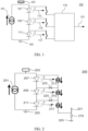
- Fig. 1 illustrates a block diagram of an individual LED short circuit detection circuit implemented by an OR logic function.
- the circuit 100 includes a current source 101 which provides current to an LED unit which includes LEDs 107, 109 and 111. More specifically, LEDs 107,109, 111 are series connected with the anode of LED 107 connected to an LED voltage 103 and the cathode of LED 111 connected to ground 105. LEDs 107, 109 and 111 are associated with individual LED sensors 113, 115 and 117 respectively. In the embodiment of FIG 1 , the LED sensors 113, 115 and 117 are each schematically represented by a sense arrow coupled to a switch.
- Outputs from the LED sensors 113, 115, 117 are coupled to LED status detector 119 which implements a logic OR function to provide a signal on status output 121 representative of an operational status of the LED unit.
- the status detector 119 is capable of detecting a short circuit of any individual LED within the LED unit.
- FIG. 1 shows the lighting circuit 100 in normal operation. Specifically, when the LEDs 107, 109 and 111 are all operating normally (neither open nor short circuited), their respective sensors 113, 115 and 117 each act as an open switch, and thus all inputs to the detector 119 are a logic LOW, for example.
- the status detector 119 implements a logic OR function to output a LOW value at status output 121 during normal operation.
- any LED becomes shorted such that its anode is shorted to its cathode, the shorted LED will stop emitting light, but can still provide a current path for the remaining series-connected LEDs to emit light, thus violating some vehicle regulations.
- shorting of one or more of LEDs 107, 109, 111 will cause its associated sensor to act as a closed switch and provide a HIGH input to status detector 119, which implements a logic OR function to cause a HIGH value status signal at output 121.
- This change in the status signal indicates that the LED unit has a failed LED and may be used to initiate any fault sequence, such as turning off current source 101 to ensure that the LED unit does not emit any light as is required by some vehicle lighting regulations.
- Fig. 2 illustrates a block diagram of an individual LED short circuit detection circuit implemented by an AND logic function.
- the circuit 200 includes a current source 201 that provides current to an LED unit which includes LEDs 207, 209 and 211. More specifically, LEDs 207, 209, 211 are series connected with the anode of LED 207 connected to an LED voltage 203 and the cathode of LED 211 connected to ground 205. LEDs 207, 209 and 211 are associated with individual LED sensors 213, 215 and 217 respectively. In the embodiment of FIG 2 , the LED sensors 213, 215 and 217 are each schematically represented by a sense arrow coupled to a current source.
- the current sources of the sensors are connected in series to provide a current path from LED voltage 203 to ground 205 through resistor 219 which acts as a detector providing a status output 221 representative of an operational status of the LED unit.
- the status detector 219 is capable of detecting a short circuit of any individual LED within the LED unit.
- FIG. 2 shows the detector output 221 in normal operation. Specifically, when the LEDs 207, 209 and 211 are all operating normally (neither open nor short circuited), their respective sensors 213, 215 and 217 act as series connected current sources to provide a current path from LED voltage 203 to ground 205. This may be seen as a logic AND function where the current source inputs are all HIGH, for example, to activate the current sources and complete the path from LED voltage 203 to ground 205. This current causes a voltage drop across resistor 219 causing the status output 221 to be HIGH in normal operation, for example.
- the shorted LED will stop emitting light, but can still provide a current path for the remaining series connected LEDs to operate normally, thus violating vehicle regulations.
- shorting of one or more of LEDS 207, 209, 211 will cause the associated sensor to deactivate the current source to interrupt the current path through resistor 219, thus changing the detector output 221 to a logic LOW value.
- This change in the status signal indicates that the LED unit has a failed LED.
- the status signal may be used to initiate any fault sequences such as turning off current source 201 to ensure that the vehicle lighting unit complies with regulations.
- Diodes 223 and 225 ensure that the current source of a sensor is disabled when the related LED is shorted, as will be discussed further in the example of FIG. 3 below.
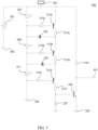
- Fig. 3 illustrates a detailed electrical schematic diagram of an individual LED short circuit detection circuit according to the present invention.
- the circuit 300 includes a current source 301 connected between LED voltage 303 and ground 305 to provide current to an LED lighting unit including LEDs 307, 309 and 311 which are connected in series between LED voltage 303 and ground 305.
- Each LED 307, 309 and 311 is associated with an individual LED sensor for sensing short circuit of a respective LED.
- LED 307 is associated with an LED sensor including PNP transistor 313a and related base resistor 315a and collector resistor 317a. Resistors 315a and 317a have a resistance value to ensure that transistor 313a is ON during normal operation of the LED 307.
- LED 309 has a similar LED sensor including transistor 313b, and resistors 315b and 317b
- LED 311 has a similar sensor including transistor 313c, and resistors 315c and 317c.
- Diodes 323 and 325 ensure that a transistor 313a, 313b and 313c is OFF when a related LED is shorted.
- Circuit 300 further includes a status output 321, which transitions from low to high value to indicate a fault when one or more of the LEDs 307, 309 or 311 become shorted.
- the signal value of output 321 is determined by operation of NPN transistor 329 which is biased by collector resistor 319 and base resistor 327.
- transistors 313a, 313b and 313c are connected in series to provide a current path from LED voltage 303 to ground 305 through resistor 327 the voltage drop of which provides a control output to NPN transistor 329. This may be considered an AND function detector in that all of the transistors 313a, 313b and 313c must be ON to turn ON transistor 329.
- LEDs 307, 309, 311 each emit light and provide a voltage divider network to drive respective transistors 313a, 313b and 313c ON.
- the current path provided by the series connected transistors causes a voltage drop across resistor 327, which provides a base voltage to drive NPN transistor 329 ON. This causes a LOW status signal value at output on 321 during normal operation. If any LED 307, 309, 311 becomes shorted, its associated transistor turns OFF to interrupt the current path provided by the series transistors 313a, 313b, 313c, which causes NPN transistor 329 to turn OFF and the status signal value at output 321 to become a HIGH value which may be used as a control signal to initiate any fault sequence of the vehicle or lighting module.
- PNP transistor 313a is turned OFF due to the base and emitter being at the same potential (i.e., LED voltage 303).
- PNP transistor 313b is turned OFF due to the base and emitter being essentially at the same potential.
- current flow through diode 323 permits a small potential difference of 0.6v, which is below the turn on threshold for transistor 313b.
- Diode 325 operates in a similar way to ensure that transistor 313c is OFF when LED 311 is shorted.
- Fig. 4 illustrates a detailed electrical schematic diagram of an individual LED short circuit detection circuit according to one embodiment of the present invention.
- the circuit 400 includes a current source 401 connected between LED voltage 403 and ground 405 to provide current to an LED lighting unit including LEDs 407, 409 and 411 which are connected in series between LED voltage 403 and ground 405.
- Each LED 407, 409 and 411 is associated with an individual LED sensor for sensing short circuit of a respective LED.
- the sensor circuit associated with LED 407 includes a PNP transistor 415a, as well as base resistor 413a and collector resistor 417a associated with the transistor 415a.
- An output of PNP transistor 415a drives NPN transistor 423a having a base resistor 419a and collector resistor 425a associated therewith. Resistance values of the resistors 413a, 417a, 419a and 425a are selected such that PNP transistor 415a and NPN transistor 423a are ON during normal operation of LED 407.
- LED 409 has a similar sensor circuit including transistors 415b and 423b, as well as resistors 413b, 417b, 419b and 425b.
- LED 411 has a similar sensor circuit including transistors 415c and 423c, as well as resistors 413c, 417c, 419c and 425c.
- the sensor circuits are provided in parallel with one another and provide a common circuit detector output 421.
- a collector terminal of each of the NPN transistors 423a, 423b, 423c is connected to respective diodes 427a, 427b and 427c, the cathodes of which are connected to ground 405 through resistor 433.
- Status output 421 transitions from LOW to HIGH value to indicate a fault when one or more of LEDs 407, 409, 411 becomes shorted.
- LEDs 407, 409, 411 each emit light and provide a voltage divider network to drive respective transistors 415a, 415b and 415c ON.
- the current path provided by each of these transistors provides a base voltage to drive respective NPN transistors 423a, 423b, and 423c ON.
- any LED 407, 409, 411 becomes shorted, its associated PNP transistor turns OFF to interrupt the current path through its collector voltage divider network causing associated NPN transistor to turn OFF to forward bias the associated output diode.
- Forward bias of any diode 427a, 427b or 427c causes the status signal value at output 421 to become a HIGH value, which may be used as a control signal to initiate any fault sequence of the vehicle or lighting module.
- PNP transistor 415a is turned OFF due to the base and emitter being at the same potential (i.e., LED voltage 403). This interrupts the current path through the voltage divider network 417a and 419a to remove the base voltage from NPN transistor 423a, putting transistor 423a in an OFF state and removing ground from the anode of diode 427a. Diode 427a then becomes forward biased to pull the status output 421 to a HIGH value. Short circuit of LED 409 or 411 will cause similar operation of their respective sensor circuitry to transition the output 421 to HIGH value, which may be used as a control signal to initiate any fault sequence of the vehicle or lighting module.
Landscapes
- Engineering & Computer Science (AREA)
- Mechanical Engineering (AREA)
- Lighting Device Outwards From Vehicle And Optical Signal (AREA)
- Circuit Arrangement For Electric Light Sources In General (AREA)
Claims (8)
- LED-Beleuchtungsschaltung (300) zum Erkennen des Ausfalls einer einzelnen LED, umfassend:eine Beleuchtungseinheit mit einer Vielzahl von in Reihe geschalteten LEDs (307, 309, 311,) eine Vielzahl von LED-Sensoren, die jeweils einer der LEDs zugeordnet sind, wobei jeder LED-Sensor einen PNP-Transistor (313a, 313b, 313c), einen Kollektorwiderstand (317a, 317b, 317c) und einen Basiswiderstand (315a, 315b, 315c) umfasst, wobei die Widerstandswerte des Basiswiderstandes und des Kollektorwiderstandes so angepasst sind, dass sichergestellt wird, dass der entsprechende Transistor (313a, 313b, 313c) während des normalen Betriebs der entsprechenden LED (307, 309, 311) EIN ist; undeinen Beleuchtungseinheit-Statussignalgenerator, der mit der Mehrzahl von LED-Sensoren gekoppelt ist, die so konfiguriert sind, dass sie ein Statussignal (321) bereitstellen, das einen Fehler anzeigt, wenn irgendeine einzelne LED kurzgeschlossen ist, wobei das Statussignal durch den Betrieb eines NPN-Transistors (329) der LED-Beleuchtungsschaltung (300) bestimmt und durch einen Kollektorwiderstand (319) und einen Basiswiderstand (327) vorgespannt wird;dadurch gekennzeichnet, dass die PNP-Transistoren (313a, 313b, 313c) der LED-Sensoren in Reihe geschaltet sind, um einen ersten Strompfad durch den Basiswiderstand (327) des NPN-Transistors (329) bereitzustellen, wodurch ein Steuerausgang für den NPN-Transistor (329) bereitgestellt wird, undwobei einige der LED-Sensoren eine Diode (323, 325) umfassen, die so konfiguriert ist, dass sie sicherstellt, dass der entsprechende PNP-Transistor des entsprechenden LED-Sensors AUS ist, wenn die entsprechende LED kurzgeschlossen ist.
- LED-Beleuchtungsschaltung nach Anspruch 1, wobei der Beleuchtungseinheit-Statussignalgenerator so konfiguriert ist, dass er eine logische UND-Funktion implementiert, um das Statussignal zu erzeugen, das einen Fehler anzeigt, wenn irgendeine einzelne LED kurzgeschlossen ist.
- LED-Beleuchtungsschaltung nach Anspruch 1, wobei die PNP-Transistoren (313a, 313b, 313c) der mehreren LED-Sensoren in Reihe zueinander angeordnet sind, um einen Strompfad von einer LED-Spannungsquelle zu einer Masse zu bilden.
- LED-Beleuchtungsschaltung nach Anspruch 1, wobei die PNP-Transistoren (313a, 313b, 313c) der Mehrzahl von LED-Sensoren in Reihe zueinander in einer UND-Konfiguration angeordnet sind.
- LED-Beleuchtungsschaltung nach Anspruch 4, wobei jeder der PNP-Transistoren (313a, 313b, 313c) EIN ist, wenn alle der mehreren LEDs (307, 309, 311) einen normalen Betriebsstatus haben, und der LED-Beleuchtungseinheits-Statussignalgenerator ein LOW-Statussignal ausgibt, das einen normalen Status der LED-Beleuchtungseinheit anzeigt.
- LED-Beleuchtungsschaltung nach Anspruch 5, wobei, wenn eine beliebige LED der Mehrzahl von LEDs (307, 309, 311) kurzgeschlossen wird, ihr zugehöriger PNP-Transistor (313a, 313b, 313c) auf AUS schaltet und der LED-Beleuchtungseinheits-Statussignalgenerator ein HIGH-Statussignal ausgibt, das einen Fehlerstatus der LED-Beleuchtungseinheit anzeigt.
- Fahrzeugaußenbeleuchtungsvorrichtung mit der LED-Beleuchtungsschaltung nach Anspruch 1.
- Kraftfahrzeug, umfassend: eine Beleuchtungsvorrichtung, die an einer Außenseite des Kraftfahrzeugs vorgesehen ist, wobei die Beleuchtungsvorrichtung die LED-Beleuchtungsschaltung nach Anspruch 1 umfasst.
Applications Claiming Priority (1)
| Application Number | Priority Date | Filing Date | Title |
|---|---|---|---|
| US15/881,891 US10178734B1 (en) | 2018-01-29 | 2018-01-29 | Individual LED short circuit detection |
Publications (2)
| Publication Number | Publication Date |
|---|---|
| EP3517364A1 EP3517364A1 (de) | 2019-07-31 |
| EP3517364B1 true EP3517364B1 (de) | 2023-08-23 |
Family
ID=64815770
Family Applications (1)
| Application Number | Title | Priority Date | Filing Date |
|---|---|---|---|
| EP19154056.6A Active EP3517364B1 (de) | 2018-01-29 | 2019-01-28 | Einzelne led-kurzschlusserkennung |
Country Status (3)
| Country | Link |
|---|---|
| US (1) | US10178734B1 (de) |
| EP (1) | EP3517364B1 (de) |
| CN (1) | CN110099480B (de) |
Families Citing this family (4)
| Publication number | Priority date | Publication date | Assignee | Title |
|---|---|---|---|---|
| CN111381109B (zh) * | 2018-12-27 | 2022-07-08 | 启碁科技股份有限公司 | 电子装置 |
| DE102021100854A1 (de) | 2021-01-18 | 2022-07-21 | HELLA GmbH & Co. KGaA | Steuer- und/oder Regelungsmittel, Schaltungsanordnung und Verfahren zur Ansteuerung von Leuchtdioden in einem Leuchtdiodenfeld |
| EP4068910A1 (de) * | 2021-03-29 | 2022-10-05 | ZKW Group GmbH | Kurzschlussfehlererkennende beleuchtungsvorrichtung für einen kraftfahrzeugscheinwerfer |
| WO2024218880A1 (ja) * | 2023-04-19 | 2024-10-24 | 三菱電機株式会社 | 故障検出回路及び乗員監視装置 |
Family Cites Families (12)
| Publication number | Priority date | Publication date | Assignee | Title |
|---|---|---|---|---|
| US7800876B2 (en) | 2006-01-09 | 2010-09-21 | Microsemi Corp. - Analog Mixed Signal Group Ltd. | Fault detection mechanism for LED backlighting |
| AT504949B1 (de) * | 2007-02-20 | 2008-11-15 | Zizala Lichtsysteme Gmbh | Schaltungsanordnung zur erkennung eines kurzschlusses von leuchtdioden |
| KR101955034B1 (ko) * | 2011-12-07 | 2019-03-07 | 매그나칩 반도체 유한회사 | Led 어레이 쇼트여부 감지회로 및 이를 이용한 led 구동장치 |
| WO2013110052A1 (en) * | 2012-01-20 | 2013-07-25 | Osram Sylvania Inc. | Lighting systems with uniform led brightness |
| US8896319B2 (en) * | 2012-02-24 | 2014-11-25 | Richtek Technology Corporation | Light emitting device control circuit and short detection circuit thereof |
| CN102970803A (zh) * | 2012-12-05 | 2013-03-13 | 成都芯源系统有限公司 | 驱动多串发光二极管的装置和方法 |
| JP2015026604A (ja) * | 2013-06-18 | 2015-02-05 | パナソニックIpマネジメント株式会社 | 半導体光源駆動装置及び投写型表示装置 |
| DE102014118795A1 (de) * | 2013-12-18 | 2015-06-18 | Panasonic Intellectual Property Management Co., Ltd. | Beleuchtungsbaugruppe und Leuchte |
| US9713210B2 (en) * | 2015-09-15 | 2017-07-18 | Semiconductor Components Industries, Llc | LED lighting system |
| JP6723064B2 (ja) * | 2016-05-10 | 2020-07-15 | ローム株式会社 | 地絡検出回路、異常検出回路、発光装置、車両 |
| JP6829947B2 (ja) * | 2016-05-17 | 2021-02-17 | ローム株式会社 | 発光素子駆動用半導体集積回路、発光素子駆動装置、発光装置、車両 |
| US9942971B2 (en) * | 2016-08-15 | 2018-04-10 | Ford Global Technologies, Llc | Detecting outages in a LED lamp assembly |
-
2018
- 2018-01-29 US US15/881,891 patent/US10178734B1/en active Active
-
2019
- 2019-01-28 EP EP19154056.6A patent/EP3517364B1/de active Active
- 2019-01-29 CN CN201910088645.8A patent/CN110099480B/zh active Active
Also Published As
| Publication number | Publication date |
|---|---|
| CN110099480A (zh) | 2019-08-06 |
| EP3517364A1 (de) | 2019-07-31 |
| CN110099480B (zh) | 2021-09-10 |
| US10178734B1 (en) | 2019-01-08 |
Similar Documents
| Publication | Publication Date | Title |
|---|---|---|
| EP3517364B1 (de) | Einzelne led-kurzschlusserkennung | |
| US8084960B2 (en) | Circuits and methods for powering light source with balanced currents | |
| JP2006210219A (ja) | 車両用灯具の点灯制御回路 | |
| CN104703337B (zh) | 车辆用灯具 | |
| EP2966943B1 (de) | Vorrichtung zum steuern von leuchtdioden | |
| CN108235506B (zh) | 用于车灯组件的恒定电流功率驱动器电路 | |
| KR20170045218A (ko) | Led 주행등 제어 및 상태를 위한 장치 및 방법 | |
| US9085260B2 (en) | Light source for motor vehicles | |
| CN112566817A (zh) | 点亮电路及车辆用灯具 | |
| EP2881284B1 (de) | Richtungsanzeigende vorrichtung | |
| EP3030051A1 (de) | Signalumsetzerschaltung zum Dimmen eines Leuchtmittels | |
| JP2008168706A (ja) | 光源ユニット群点灯装置 | |
| US11919441B2 (en) | Lamp control device | |
| EP3932738A1 (de) | Fahrzeugleuchte und beleuchtungsschaltung | |
| KR102774921B1 (ko) | 광원 구동장치 | |
| US20200092969A1 (en) | Vehicle lighting device | |
| JP7393414B2 (ja) | 車両用灯具および点灯回路 | |
| EP3086377B1 (de) | Led-treiberschaltung und verfahren zur steuerung der led-treiberschaltung | |
| CN104509212A (zh) | 灯驱动电源、以及灯驱动电源的控制方法 | |
| US11910504B2 (en) | Light source module and lighting circuit | |
| JP7550094B2 (ja) | 車両用灯具 | |
| JP6703577B2 (ja) | 電源装置の保護装置 | |
| CN112533320B (zh) | 发光二极管控制装置 | |
| JP2025080904A (ja) | 光源の駆動回路、車両用灯具 | |
| US20210014945A1 (en) | Lighting circuit |
Legal Events
| Date | Code | Title | Description |
|---|---|---|---|
| PUAI | Public reference made under article 153(3) epc to a published international application that has entered the european phase |
Free format text: ORIGINAL CODE: 0009012 |
|
| STAA | Information on the status of an ep patent application or granted ep patent |
Free format text: STATUS: REQUEST FOR EXAMINATION WAS MADE |
|
| 17P | Request for examination filed |
Effective date: 20190128 |
|
| AK | Designated contracting states |
Kind code of ref document: A1 Designated state(s): AL AT BE BG CH CY CZ DE DK EE ES FI FR GB GR HR HU IE IS IT LI LT LU LV MC MK MT NL NO PL PT RO RS SE SI SK SM TR |
|
| AX | Request for extension of the european patent |
Extension state: BA ME |
|
| STAA | Information on the status of an ep patent application or granted ep patent |
Free format text: STATUS: EXAMINATION IS IN PROGRESS |
|
| 17Q | First examination report despatched |
Effective date: 20200527 |
|
| GRAP | Despatch of communication of intention to grant a patent |
Free format text: ORIGINAL CODE: EPIDOSNIGR1 |
|
| STAA | Information on the status of an ep patent application or granted ep patent |
Free format text: STATUS: GRANT OF PATENT IS INTENDED |
|
| RIC1 | Information provided on ipc code assigned before grant |
Ipc: H05B 45/395 20200101ALI20230203BHEP Ipc: H05B 45/54 20200101ALI20230203BHEP Ipc: H05B 45/48 20200101ALI20230203BHEP Ipc: B60Q 11/00 20060101AFI20230203BHEP |
|
| INTG | Intention to grant announced |
Effective date: 20230315 |
|
| P01 | Opt-out of the competence of the unified patent court (upc) registered |
Effective date: 20230602 |
|
| GRAS | Grant fee paid |
Free format text: ORIGINAL CODE: EPIDOSNIGR3 |
|
| GRAA | (expected) grant |
Free format text: ORIGINAL CODE: 0009210 |
|
| STAA | Information on the status of an ep patent application or granted ep patent |
Free format text: STATUS: THE PATENT HAS BEEN GRANTED |
|
| AK | Designated contracting states |
Kind code of ref document: B1 Designated state(s): AL AT BE BG CH CY CZ DE DK EE ES FI FR GB GR HR HU IE IS IT LI LT LU LV MC MK MT NL NO PL PT RO RS SE SI SK SM TR |
|
| REG | Reference to a national code |
Ref country code: GB Ref legal event code: FG4D |
|
| REG | Reference to a national code |
Ref country code: CH Ref legal event code: EP |
|
| REG | Reference to a national code |
Ref country code: DE Ref legal event code: R096 Ref document number: 602019035396 Country of ref document: DE |
|
| REG | Reference to a national code |
Ref country code: IE Ref legal event code: FG4D |
|
| REG | Reference to a national code |
Ref country code: LT Ref legal event code: MG9D |
|
| REG | Reference to a national code |
Ref country code: NL Ref legal event code: MP Effective date: 20230823 |
|
| REG | Reference to a national code |
Ref country code: AT Ref legal event code: MK05 Ref document number: 1602228 Country of ref document: AT Kind code of ref document: T Effective date: 20230823 |
|
| PG25 | Lapsed in a contracting state [announced via postgrant information from national office to epo] |
Ref country code: GR Free format text: LAPSE BECAUSE OF FAILURE TO SUBMIT A TRANSLATION OF THE DESCRIPTION OR TO PAY THE FEE WITHIN THE PRESCRIBED TIME-LIMIT Effective date: 20231124 |
|
| PG25 | Lapsed in a contracting state [announced via postgrant information from national office to epo] |
Ref country code: IS Free format text: LAPSE BECAUSE OF FAILURE TO SUBMIT A TRANSLATION OF THE DESCRIPTION OR TO PAY THE FEE WITHIN THE PRESCRIBED TIME-LIMIT Effective date: 20231223 |
|
| PG25 | Lapsed in a contracting state [announced via postgrant information from national office to epo] |
Ref country code: SE Free format text: LAPSE BECAUSE OF FAILURE TO SUBMIT A TRANSLATION OF THE DESCRIPTION OR TO PAY THE FEE WITHIN THE PRESCRIBED TIME-LIMIT Effective date: 20230823 Ref country code: RS Free format text: LAPSE BECAUSE OF FAILURE TO SUBMIT A TRANSLATION OF THE DESCRIPTION OR TO PAY THE FEE WITHIN THE PRESCRIBED TIME-LIMIT Effective date: 20230823 Ref country code: PT Free format text: LAPSE BECAUSE OF FAILURE TO SUBMIT A TRANSLATION OF THE DESCRIPTION OR TO PAY THE FEE WITHIN THE PRESCRIBED TIME-LIMIT Effective date: 20231226 Ref country code: NO Free format text: LAPSE BECAUSE OF FAILURE TO SUBMIT A TRANSLATION OF THE DESCRIPTION OR TO PAY THE FEE WITHIN THE PRESCRIBED TIME-LIMIT Effective date: 20231123 Ref country code: NL Free format text: LAPSE BECAUSE OF FAILURE TO SUBMIT A TRANSLATION OF THE DESCRIPTION OR TO PAY THE FEE WITHIN THE PRESCRIBED TIME-LIMIT Effective date: 20230823 Ref country code: LV Free format text: LAPSE BECAUSE OF FAILURE TO SUBMIT A TRANSLATION OF THE DESCRIPTION OR TO PAY THE FEE WITHIN THE PRESCRIBED TIME-LIMIT Effective date: 20230823 Ref country code: LT Free format text: LAPSE BECAUSE OF FAILURE TO SUBMIT A TRANSLATION OF THE DESCRIPTION OR TO PAY THE FEE WITHIN THE PRESCRIBED TIME-LIMIT Effective date: 20230823 Ref country code: IS Free format text: LAPSE BECAUSE OF FAILURE TO SUBMIT A TRANSLATION OF THE DESCRIPTION OR TO PAY THE FEE WITHIN THE PRESCRIBED TIME-LIMIT Effective date: 20231223 Ref country code: HR Free format text: LAPSE BECAUSE OF FAILURE TO SUBMIT A TRANSLATION OF THE DESCRIPTION OR TO PAY THE FEE WITHIN THE PRESCRIBED TIME-LIMIT Effective date: 20230823 Ref country code: GR Free format text: LAPSE BECAUSE OF FAILURE TO SUBMIT A TRANSLATION OF THE DESCRIPTION OR TO PAY THE FEE WITHIN THE PRESCRIBED TIME-LIMIT Effective date: 20231124 Ref country code: FI Free format text: LAPSE BECAUSE OF FAILURE TO SUBMIT A TRANSLATION OF THE DESCRIPTION OR TO PAY THE FEE WITHIN THE PRESCRIBED TIME-LIMIT Effective date: 20230823 Ref country code: AT Free format text: LAPSE BECAUSE OF FAILURE TO SUBMIT A TRANSLATION OF THE DESCRIPTION OR TO PAY THE FEE WITHIN THE PRESCRIBED TIME-LIMIT Effective date: 20230823 |
|
| PG25 | Lapsed in a contracting state [announced via postgrant information from national office to epo] |
Ref country code: PL Free format text: LAPSE BECAUSE OF FAILURE TO SUBMIT A TRANSLATION OF THE DESCRIPTION OR TO PAY THE FEE WITHIN THE PRESCRIBED TIME-LIMIT Effective date: 20230823 |
|
| PG25 | Lapsed in a contracting state [announced via postgrant information from national office to epo] |
Ref country code: ES Free format text: LAPSE BECAUSE OF FAILURE TO SUBMIT A TRANSLATION OF THE DESCRIPTION OR TO PAY THE FEE WITHIN THE PRESCRIBED TIME-LIMIT Effective date: 20230823 |
|
| PG25 | Lapsed in a contracting state [announced via postgrant information from national office to epo] |
Ref country code: SM Free format text: LAPSE BECAUSE OF FAILURE TO SUBMIT A TRANSLATION OF THE DESCRIPTION OR TO PAY THE FEE WITHIN THE PRESCRIBED TIME-LIMIT Effective date: 20230823 Ref country code: RO Free format text: LAPSE BECAUSE OF FAILURE TO SUBMIT A TRANSLATION OF THE DESCRIPTION OR TO PAY THE FEE WITHIN THE PRESCRIBED TIME-LIMIT Effective date: 20230823 Ref country code: ES Free format text: LAPSE BECAUSE OF FAILURE TO SUBMIT A TRANSLATION OF THE DESCRIPTION OR TO PAY THE FEE WITHIN THE PRESCRIBED TIME-LIMIT Effective date: 20230823 Ref country code: EE Free format text: LAPSE BECAUSE OF FAILURE TO SUBMIT A TRANSLATION OF THE DESCRIPTION OR TO PAY THE FEE WITHIN THE PRESCRIBED TIME-LIMIT Effective date: 20230823 Ref country code: DK Free format text: LAPSE BECAUSE OF FAILURE TO SUBMIT A TRANSLATION OF THE DESCRIPTION OR TO PAY THE FEE WITHIN THE PRESCRIBED TIME-LIMIT Effective date: 20230823 Ref country code: CZ Free format text: LAPSE BECAUSE OF FAILURE TO SUBMIT A TRANSLATION OF THE DESCRIPTION OR TO PAY THE FEE WITHIN THE PRESCRIBED TIME-LIMIT Effective date: 20230823 Ref country code: SK Free format text: LAPSE BECAUSE OF FAILURE TO SUBMIT A TRANSLATION OF THE DESCRIPTION OR TO PAY THE FEE WITHIN THE PRESCRIBED TIME-LIMIT Effective date: 20230823 |
|
| REG | Reference to a national code |
Ref country code: DE Ref legal event code: R097 Ref document number: 602019035396 Country of ref document: DE |
|
| PG25 | Lapsed in a contracting state [announced via postgrant information from national office to epo] |
Ref country code: IT Free format text: LAPSE BECAUSE OF FAILURE TO SUBMIT A TRANSLATION OF THE DESCRIPTION OR TO PAY THE FEE WITHIN THE PRESCRIBED TIME-LIMIT Effective date: 20230823 |
|
| PLBE | No opposition filed within time limit |
Free format text: ORIGINAL CODE: 0009261 |
|
| STAA | Information on the status of an ep patent application or granted ep patent |
Free format text: STATUS: NO OPPOSITION FILED WITHIN TIME LIMIT |
|
| 26N | No opposition filed |
Effective date: 20240524 |
|
| PG25 | Lapsed in a contracting state [announced via postgrant information from national office to epo] |
Ref country code: SI Free format text: LAPSE BECAUSE OF FAILURE TO SUBMIT A TRANSLATION OF THE DESCRIPTION OR TO PAY THE FEE WITHIN THE PRESCRIBED TIME-LIMIT Effective date: 20230823 |
|
| PG25 | Lapsed in a contracting state [announced via postgrant information from national office to epo] |
Ref country code: MC Free format text: LAPSE BECAUSE OF FAILURE TO SUBMIT A TRANSLATION OF THE DESCRIPTION OR TO PAY THE FEE WITHIN THE PRESCRIBED TIME-LIMIT Effective date: 20230823 |
|
| PG25 | Lapsed in a contracting state [announced via postgrant information from national office to epo] |
Ref country code: MC Free format text: LAPSE BECAUSE OF FAILURE TO SUBMIT A TRANSLATION OF THE DESCRIPTION OR TO PAY THE FEE WITHIN THE PRESCRIBED TIME-LIMIT Effective date: 20230823 |
|
| REG | Reference to a national code |
Ref country code: CH Ref legal event code: PL |
|
| PG25 | Lapsed in a contracting state [announced via postgrant information from national office to epo] |
Ref country code: LU Free format text: LAPSE BECAUSE OF NON-PAYMENT OF DUE FEES Effective date: 20240128 |
|
| GBPC | Gb: european patent ceased through non-payment of renewal fee |
Effective date: 20240128 |
|
| PG25 | Lapsed in a contracting state [announced via postgrant information from national office to epo] |
Ref country code: LU Free format text: LAPSE BECAUSE OF NON-PAYMENT OF DUE FEES Effective date: 20240128 |
|
| PG25 | Lapsed in a contracting state [announced via postgrant information from national office to epo] |
Ref country code: GB Free format text: LAPSE BECAUSE OF NON-PAYMENT OF DUE FEES Effective date: 20240128 |
|
| PG25 | Lapsed in a contracting state [announced via postgrant information from national office to epo] |
Ref country code: BE Free format text: LAPSE BECAUSE OF NON-PAYMENT OF DUE FEES Effective date: 20240131 |
|
| PG25 | Lapsed in a contracting state [announced via postgrant information from national office to epo] |
Ref country code: CH Free format text: LAPSE BECAUSE OF NON-PAYMENT OF DUE FEES Effective date: 20240131 |
|
| PG25 | Lapsed in a contracting state [announced via postgrant information from national office to epo] |
Ref country code: GB Free format text: LAPSE BECAUSE OF NON-PAYMENT OF DUE FEES Effective date: 20240128 Ref country code: CH Free format text: LAPSE BECAUSE OF NON-PAYMENT OF DUE FEES Effective date: 20240131 Ref country code: BE Free format text: LAPSE BECAUSE OF NON-PAYMENT OF DUE FEES Effective date: 20240131 |
|
| REG | Reference to a national code |
Ref country code: BE Ref legal event code: MM Effective date: 20240131 |
|
| PG25 | Lapsed in a contracting state [announced via postgrant information from national office to epo] |
Ref country code: BG Free format text: LAPSE BECAUSE OF FAILURE TO SUBMIT A TRANSLATION OF THE DESCRIPTION OR TO PAY THE FEE WITHIN THE PRESCRIBED TIME-LIMIT Effective date: 20230823 |
|
| PG25 | Lapsed in a contracting state [announced via postgrant information from national office to epo] |
Ref country code: BG Free format text: LAPSE BECAUSE OF FAILURE TO SUBMIT A TRANSLATION OF THE DESCRIPTION OR TO PAY THE FEE WITHIN THE PRESCRIBED TIME-LIMIT Effective date: 20230823 |
|
| PG25 | Lapsed in a contracting state [announced via postgrant information from national office to epo] |
Ref country code: IE Free format text: LAPSE BECAUSE OF NON-PAYMENT OF DUE FEES Effective date: 20240128 |
|
| PG25 | Lapsed in a contracting state [announced via postgrant information from national office to epo] |
Ref country code: IE Free format text: LAPSE BECAUSE OF NON-PAYMENT OF DUE FEES Effective date: 20240128 |
|
| PG25 | Lapsed in a contracting state [announced via postgrant information from national office to epo] |
Ref country code: CY Free format text: LAPSE BECAUSE OF FAILURE TO SUBMIT A TRANSLATION OF THE DESCRIPTION OR TO PAY THE FEE WITHIN THE PRESCRIBED TIME-LIMIT; INVALID AB INITIO Effective date: 20190128 |
|
| PG25 | Lapsed in a contracting state [announced via postgrant information from national office to epo] |
Ref country code: HU Free format text: LAPSE BECAUSE OF FAILURE TO SUBMIT A TRANSLATION OF THE DESCRIPTION OR TO PAY THE FEE WITHIN THE PRESCRIBED TIME-LIMIT; INVALID AB INITIO Effective date: 20190128 |
|
| PG25 | Lapsed in a contracting state [announced via postgrant information from national office to epo] |
Ref country code: TR Free format text: LAPSE BECAUSE OF FAILURE TO SUBMIT A TRANSLATION OF THE DESCRIPTION OR TO PAY THE FEE WITHIN THE PRESCRIBED TIME-LIMIT Effective date: 20230823 |
|
| PGFP | Annual fee paid to national office [announced via postgrant information from national office to epo] |
Ref country code: DE Payment date: 20260114 Year of fee payment: 8 |
|
| PGFP | Annual fee paid to national office [announced via postgrant information from national office to epo] |
Ref country code: FR Payment date: 20260128 Year of fee payment: 8 |