EP3517339B1 - Ladezustandsanzeigesystem - Google Patents
Ladezustandsanzeigesystem Download PDFInfo
- Publication number
- EP3517339B1 EP3517339B1 EP19152339.8A EP19152339A EP3517339B1 EP 3517339 B1 EP3517339 B1 EP 3517339B1 EP 19152339 A EP19152339 A EP 19152339A EP 3517339 B1 EP3517339 B1 EP 3517339B1
- Authority
- EP
- European Patent Office
- Prior art keywords
- soc
- battery
- lighting elements
- motor vehicle
- light array
- Prior art date
- Legal status (The legal status is an assumption and is not a legal conclusion. Google has not performed a legal analysis and makes no representation as to the accuracy of the status listed.)
- Active
Links
Images



Classifications
-
- B—PERFORMING OPERATIONS; TRANSPORTING
- B60—VEHICLES IN GENERAL
- B60L—PROPULSION OF ELECTRICALLY-PROPELLED VEHICLES; SUPPLYING ELECTRIC POWER FOR AUXILIARY EQUIPMENT OF ELECTRICALLY-PROPELLED VEHICLES; ELECTRODYNAMIC BRAKE SYSTEMS FOR VEHICLES IN GENERAL; MAGNETIC SUSPENSION OR LEVITATION FOR VEHICLES; MONITORING OPERATING VARIABLES OF ELECTRICALLY-PROPELLED VEHICLES; ELECTRIC SAFETY DEVICES FOR ELECTRICALLY-PROPELLED VEHICLES
- B60L3/00—Electric devices on electrically-propelled vehicles for safety purposes; Monitoring operating variables, e.g. speed, deceleration or energy consumption
- B60L3/12—Recording operating variables ; Monitoring of operating variables
-
- B—PERFORMING OPERATIONS; TRANSPORTING
- B60—VEHICLES IN GENERAL
- B60Q—ARRANGEMENT OF SIGNALLING OR LIGHTING DEVICES, THE MOUNTING OR SUPPORTING THEREOF OR CIRCUITS THEREFOR, FOR VEHICLES IN GENERAL
- B60Q1/00—Arrangement of optical signalling or lighting devices, the mounting or supporting thereof or circuits therefor
- B60Q1/26—Arrangement of optical signalling or lighting devices, the mounting or supporting thereof or circuits therefor the devices being primarily intended to indicate the vehicle, or parts thereof, or to give signals, to other traffic
- B60Q1/44—Arrangement of optical signalling or lighting devices, the mounting or supporting thereof or circuits therefor the devices being primarily intended to indicate the vehicle, or parts thereof, or to give signals, to other traffic for indicating braking action or preparation for braking, e.g. by detection of the foot approaching the brake pedal
-
- B—PERFORMING OPERATIONS; TRANSPORTING
- B60—VEHICLES IN GENERAL
- B60K—ARRANGEMENT OR MOUNTING OF PROPULSION UNITS OR OF TRANSMISSIONS IN VEHICLES; ARRANGEMENT OR MOUNTING OF PLURAL DIVERSE PRIME-MOVERS IN VEHICLES; AUXILIARY DRIVES FOR VEHICLES; INSTRUMENTATION OR DASHBOARDS FOR VEHICLES; ARRANGEMENTS IN CONNECTION WITH COOLING, AIR INTAKE, GAS EXHAUST OR FUEL SUPPLY OF PROPULSION UNITS IN VEHICLES
- B60K35/00—Instruments specially adapted for vehicles; Arrangement of instruments in or on vehicles
- B60K35/10—Input arrangements, i.e. from user to vehicle, associated with vehicle functions or specially adapted therefor
-
- B—PERFORMING OPERATIONS; TRANSPORTING
- B60—VEHICLES IN GENERAL
- B60K—ARRANGEMENT OR MOUNTING OF PROPULSION UNITS OR OF TRANSMISSIONS IN VEHICLES; ARRANGEMENT OR MOUNTING OF PLURAL DIVERSE PRIME-MOVERS IN VEHICLES; AUXILIARY DRIVES FOR VEHICLES; INSTRUMENTATION OR DASHBOARDS FOR VEHICLES; ARRANGEMENTS IN CONNECTION WITH COOLING, AIR INTAKE, GAS EXHAUST OR FUEL SUPPLY OF PROPULSION UNITS IN VEHICLES
- B60K35/00—Instruments specially adapted for vehicles; Arrangement of instruments in or on vehicles
- B60K35/20—Output arrangements, i.e. from vehicle to user, associated with vehicle functions or specially adapted therefor
- B60K35/21—Output arrangements, i.e. from vehicle to user, associated with vehicle functions or specially adapted therefor using visual output, e.g. blinking lights or matrix displays
- B60K35/22—Display screens
-
- B—PERFORMING OPERATIONS; TRANSPORTING
- B60—VEHICLES IN GENERAL
- B60K—ARRANGEMENT OR MOUNTING OF PROPULSION UNITS OR OF TRANSMISSIONS IN VEHICLES; ARRANGEMENT OR MOUNTING OF PLURAL DIVERSE PRIME-MOVERS IN VEHICLES; AUXILIARY DRIVES FOR VEHICLES; INSTRUMENTATION OR DASHBOARDS FOR VEHICLES; ARRANGEMENTS IN CONNECTION WITH COOLING, AIR INTAKE, GAS EXHAUST OR FUEL SUPPLY OF PROPULSION UNITS IN VEHICLES
- B60K35/00—Instruments specially adapted for vehicles; Arrangement of instruments in or on vehicles
- B60K35/20—Output arrangements, i.e. from vehicle to user, associated with vehicle functions or specially adapted therefor
- B60K35/28—Output arrangements, i.e. from vehicle to user, associated with vehicle functions or specially adapted therefor characterised by the type of the output information, e.g. video entertainment or vehicle dynamics information; characterised by the purpose of the output information, e.g. for attracting the attention of the driver
-
- B—PERFORMING OPERATIONS; TRANSPORTING
- B60—VEHICLES IN GENERAL
- B60K—ARRANGEMENT OR MOUNTING OF PROPULSION UNITS OR OF TRANSMISSIONS IN VEHICLES; ARRANGEMENT OR MOUNTING OF PLURAL DIVERSE PRIME-MOVERS IN VEHICLES; AUXILIARY DRIVES FOR VEHICLES; INSTRUMENTATION OR DASHBOARDS FOR VEHICLES; ARRANGEMENTS IN CONNECTION WITH COOLING, AIR INTAKE, GAS EXHAUST OR FUEL SUPPLY OF PROPULSION UNITS IN VEHICLES
- B60K35/00—Instruments specially adapted for vehicles; Arrangement of instruments in or on vehicles
- B60K35/60—Instruments characterised by their location or relative disposition in or on vehicles
-
- B—PERFORMING OPERATIONS; TRANSPORTING
- B60—VEHICLES IN GENERAL
- B60K—ARRANGEMENT OR MOUNTING OF PROPULSION UNITS OR OF TRANSMISSIONS IN VEHICLES; ARRANGEMENT OR MOUNTING OF PLURAL DIVERSE PRIME-MOVERS IN VEHICLES; AUXILIARY DRIVES FOR VEHICLES; INSTRUMENTATION OR DASHBOARDS FOR VEHICLES; ARRANGEMENTS IN CONNECTION WITH COOLING, AIR INTAKE, GAS EXHAUST OR FUEL SUPPLY OF PROPULSION UNITS IN VEHICLES
- B60K35/00—Instruments specially adapted for vehicles; Arrangement of instruments in or on vehicles
- B60K35/80—Arrangements for controlling instruments
-
- B—PERFORMING OPERATIONS; TRANSPORTING
- B60—VEHICLES IN GENERAL
- B60K—ARRANGEMENT OR MOUNTING OF PROPULSION UNITS OR OF TRANSMISSIONS IN VEHICLES; ARRANGEMENT OR MOUNTING OF PLURAL DIVERSE PRIME-MOVERS IN VEHICLES; AUXILIARY DRIVES FOR VEHICLES; INSTRUMENTATION OR DASHBOARDS FOR VEHICLES; ARRANGEMENTS IN CONNECTION WITH COOLING, AIR INTAKE, GAS EXHAUST OR FUEL SUPPLY OF PROPULSION UNITS IN VEHICLES
- B60K35/00—Instruments specially adapted for vehicles; Arrangement of instruments in or on vehicles
- B60K35/80—Arrangements for controlling instruments
- B60K35/81—Arrangements for controlling instruments for controlling displays
-
- B—PERFORMING OPERATIONS; TRANSPORTING
- B60—VEHICLES IN GENERAL
- B60L—PROPULSION OF ELECTRICALLY-PROPELLED VEHICLES; SUPPLYING ELECTRIC POWER FOR AUXILIARY EQUIPMENT OF ELECTRICALLY-PROPELLED VEHICLES; ELECTRODYNAMIC BRAKE SYSTEMS FOR VEHICLES IN GENERAL; MAGNETIC SUSPENSION OR LEVITATION FOR VEHICLES; MONITORING OPERATING VARIABLES OF ELECTRICALLY-PROPELLED VEHICLES; ELECTRIC SAFETY DEVICES FOR ELECTRICALLY-PROPELLED VEHICLES
- B60L58/00—Methods or circuit arrangements for monitoring or controlling batteries or fuel cells, specially adapted for electric vehicles
- B60L58/10—Methods or circuit arrangements for monitoring or controlling batteries or fuel cells, specially adapted for electric vehicles for monitoring or controlling batteries
- B60L58/12—Methods or circuit arrangements for monitoring or controlling batteries or fuel cells, specially adapted for electric vehicles for monitoring or controlling batteries responding to state of charge [SoC]
-
- B—PERFORMING OPERATIONS; TRANSPORTING
- B60—VEHICLES IN GENERAL
- B60Q—ARRANGEMENT OF SIGNALLING OR LIGHTING DEVICES, THE MOUNTING OR SUPPORTING THEREOF OR CIRCUITS THEREFOR, FOR VEHICLES IN GENERAL
- B60Q1/00—Arrangement of optical signalling or lighting devices, the mounting or supporting thereof or circuits therefor
- B60Q1/26—Arrangement of optical signalling or lighting devices, the mounting or supporting thereof or circuits therefor the devices being primarily intended to indicate the vehicle, or parts thereof, or to give signals, to other traffic
-
- B—PERFORMING OPERATIONS; TRANSPORTING
- B60—VEHICLES IN GENERAL
- B60K—ARRANGEMENT OR MOUNTING OF PROPULSION UNITS OR OF TRANSMISSIONS IN VEHICLES; ARRANGEMENT OR MOUNTING OF PLURAL DIVERSE PRIME-MOVERS IN VEHICLES; AUXILIARY DRIVES FOR VEHICLES; INSTRUMENTATION OR DASHBOARDS FOR VEHICLES; ARRANGEMENTS IN CONNECTION WITH COOLING, AIR INTAKE, GAS EXHAUST OR FUEL SUPPLY OF PROPULSION UNITS IN VEHICLES
- B60K2360/00—Indexing scheme associated with groups B60K35/00 or B60K37/00 relating to details of instruments or dashboards
- B60K2360/16—Type of output information
- B60K2360/169—Remaining operating distance or charge
-
- B—PERFORMING OPERATIONS; TRANSPORTING
- B60—VEHICLES IN GENERAL
- B60K—ARRANGEMENT OR MOUNTING OF PROPULSION UNITS OR OF TRANSMISSIONS IN VEHICLES; ARRANGEMENT OR MOUNTING OF PLURAL DIVERSE PRIME-MOVERS IN VEHICLES; AUXILIARY DRIVES FOR VEHICLES; INSTRUMENTATION OR DASHBOARDS FOR VEHICLES; ARRANGEMENTS IN CONNECTION WITH COOLING, AIR INTAKE, GAS EXHAUST OR FUEL SUPPLY OF PROPULSION UNITS IN VEHICLES
- B60K2360/00—Indexing scheme associated with groups B60K35/00 or B60K37/00 relating to details of instruments or dashboards
- B60K2360/20—Optical features of instruments
- B60K2360/33—Illumination features
- B60K2360/332—Light emitting diodes
-
- B—PERFORMING OPERATIONS; TRANSPORTING
- B60—VEHICLES IN GENERAL
- B60K—ARRANGEMENT OR MOUNTING OF PROPULSION UNITS OR OF TRANSMISSIONS IN VEHICLES; ARRANGEMENT OR MOUNTING OF PLURAL DIVERSE PRIME-MOVERS IN VEHICLES; AUXILIARY DRIVES FOR VEHICLES; INSTRUMENTATION OR DASHBOARDS FOR VEHICLES; ARRANGEMENTS IN CONNECTION WITH COOLING, AIR INTAKE, GAS EXHAUST OR FUEL SUPPLY OF PROPULSION UNITS IN VEHICLES
- B60K2360/00—Indexing scheme associated with groups B60K35/00 or B60K37/00 relating to details of instruments or dashboards
- B60K2360/20—Optical features of instruments
- B60K2360/33—Illumination features
- B60K2360/338—Light strips
-
- B—PERFORMING OPERATIONS; TRANSPORTING
- B60—VEHICLES IN GENERAL
- B60K—ARRANGEMENT OR MOUNTING OF PROPULSION UNITS OR OF TRANSMISSIONS IN VEHICLES; ARRANGEMENT OR MOUNTING OF PLURAL DIVERSE PRIME-MOVERS IN VEHICLES; AUXILIARY DRIVES FOR VEHICLES; INSTRUMENTATION OR DASHBOARDS FOR VEHICLES; ARRANGEMENTS IN CONNECTION WITH COOLING, AIR INTAKE, GAS EXHAUST OR FUEL SUPPLY OF PROPULSION UNITS IN VEHICLES
- B60K2360/00—Indexing scheme associated with groups B60K35/00 or B60K37/00 relating to details of instruments or dashboards
- B60K2360/55—Remote control arrangements
-
- B—PERFORMING OPERATIONS; TRANSPORTING
- B60—VEHICLES IN GENERAL
- B60K—ARRANGEMENT OR MOUNTING OF PROPULSION UNITS OR OF TRANSMISSIONS IN VEHICLES; ARRANGEMENT OR MOUNTING OF PLURAL DIVERSE PRIME-MOVERS IN VEHICLES; AUXILIARY DRIVES FOR VEHICLES; INSTRUMENTATION OR DASHBOARDS FOR VEHICLES; ARRANGEMENTS IN CONNECTION WITH COOLING, AIR INTAKE, GAS EXHAUST OR FUEL SUPPLY OF PROPULSION UNITS IN VEHICLES
- B60K2360/00—Indexing scheme associated with groups B60K35/00 or B60K37/00 relating to details of instruments or dashboards
- B60K2360/77—Instrument locations other than the dashboard
- B60K2360/797—Instrument locations other than the dashboard at the vehicle exterior
-
- B—PERFORMING OPERATIONS; TRANSPORTING
- B60—VEHICLES IN GENERAL
- B60Q—ARRANGEMENT OF SIGNALLING OR LIGHTING DEVICES, THE MOUNTING OR SUPPORTING THEREOF OR CIRCUITS THEREFOR, FOR VEHICLES IN GENERAL
- B60Q2400/00—Special features or arrangements of exterior signal lamps for vehicles
- B60Q2400/20—Multi-color single source or LED matrix, e.g. yellow blinker and red brake lamp generated by single lamp
-
- Y—GENERAL TAGGING OF NEW TECHNOLOGICAL DEVELOPMENTS; GENERAL TAGGING OF CROSS-SECTIONAL TECHNOLOGIES SPANNING OVER SEVERAL SECTIONS OF THE IPC; TECHNICAL SUBJECTS COVERED BY FORMER USPC CROSS-REFERENCE ART COLLECTIONS [XRACs] AND DIGESTS
- Y02—TECHNOLOGIES OR APPLICATIONS FOR MITIGATION OR ADAPTATION AGAINST CLIMATE CHANGE
- Y02T—CLIMATE CHANGE MITIGATION TECHNOLOGIES RELATED TO TRANSPORTATION
- Y02T10/00—Road transport of goods or passengers
- Y02T10/60—Other road transportation technologies with climate change mitigation effect
- Y02T10/70—Energy storage systems for electromobility, e.g. batteries
Definitions
- a lighted ring or other lighted indicator around the vehicle charge port, and/or interior dashboard lighting is typically used to communicate the state-of-charge (SOC) of the motor vehicle during charging.
- SOC state-of-charge
- a vehicle owner or operator will typically not remain in the immediate vicinity of the charge port, or in view of the vehicle interior, during charging. Nevertheless, the vehicle owner or operator may wish to easily and periodically check on charging status.
- SOC display solution that enables a vehicle owner or operator to view charging status with ease and at a greater distance from the motor vehicle, and to do so on demand.
- Document DE 10 2014 222 695 A1 describes a method for indicating a charging process of an electrical energy storage device of a vehicle.
- the electrical energy storage device serves to supply an electrical drive motor of the vehicle with electrical energy.
- the vehicle comprises a lighting device which can be actuated in a first operating mode independently of the charging process.
- a time sequence of the charging process is determined and the time sequence of the charging process is displayed with the aid of the lighting device in a second operating mode of the lighting device.
- the present invention is directed to a state-of-charge (SOC) display system, substantially as shown in and/or described in connection with at least one of the figures, and as set forth in the claims.
- SOC state-of-charge
- all-electric and hybrid motor vehicles can be time consuming to charge.
- the battery stack typically used in such motor vehicles can take up to several hours to fully recharge.
- a lighted ring or other lighted indicator around the vehicle charge port, and/or interior dashboard lighting is typically used to communicate the state-of-charge (SOC) of the motor vehicle during charging.
- SOC state-of-charge
- a vehicle owner or operator will typically not remain in view of such conventional display solutions during charging, making monitoring of the charge status through use of conventional SOC displays inconvenient. Nevertheless, the vehicle owner or operator may wish to periodically check on charging status.
- SOC display solution that enables a vehicle owner or operator to view charging status at a greater distance from the motor vehicle, and to do so on demand.
- the present application addresses the inconvenience to all-electric and hybrid motor vehicle owners and operators described above.
- the present solution advantageously enables the motor vehicle owner or operator to view the SOC from a distance of many meters, such as tens of meters, for example.
- the present solution further advantageously enables display of the SOC of the battery on demand.
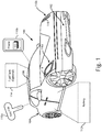
- Figure 1 shows exemplary all-electric or hybrid motor vehicle 100, according to one implementation.
- motor vehicle 100 has front end 102, rear end 104, roof 106, and exterior light arrays 116a and 116b each including multiple lighting elements 118.
- motor vehicle 100 includes battery 112, and may include optional fuel tank 114.
- remote electronic devices 110a and 110b capable of wireless communication with motor vehicle 100.
- remote electronic device 110a is a wireless key fob of motor vehicle 100
- remote electronic device 110b is a mobile phone; however, any other remote electronic device capable of transmitting radio frequency (“RF") signals or other types of signals could be used.
- RF radio frequency
- remote electronic device 110b may include SOC control application 111 for execution by a hardware processor (hardware processor of remote electronic device 110b not shown in Figure 1 ).
- a hardware processor hardware processor of remote electronic device 110b not shown in Figure 1 .
- remote electronic device 110b includes computing resources sufficient to store and execute SOC control application 111, remote electronic device 110b and SOC control application 111 can be utilized to program motor vehicle 100 to charge battery 112 during one or more desired charging intervals, such as during off-peak hours.
- battery may refer to a battery pack including multiple secondary battery cells suitable for use in providing power for propulsion of motor vehicle 100. That is to say, battery 112 may be implemented as a high voltage battery pack including multiple nickel-metal hydride (NiMH), molten-salt, or lithium-ion battery cells, for example, and capable of generating hundreds of volts.
- NiMH nickel-metal hydride
- motor vehicle 100 is depicted as an all-electric or hybrid automobile in Figure 1 , that representation is merely exemplary. More generally, motor vehicle 100 may take the form of an all-electric or hybrid automobile, truck, cart, track propelled vehicle, boat, or drone, to name a few examples.
- exterior light arrays 116a and 116b may be situated at or near front end 102 of motor vehicle 100.
- Each of exterior light arrays 116a and 116b includes multiple lighting elements 118, which may be implemented using light-emitting diodes (LEDs), for example.
- LEDs light-emitting diodes
- exterior light arrays 116a and 116b may be utilized as part of an SOC display system for displaying the SOC of battery 112, as well as to provide general lighting for motor vehicle 100 when not displaying the SOC of battery 112.
- exterior light arrays 116a and 116b may be headlamp arrays of motor vehicle 100, may provide turn signal lighting for motor vehicle 100, or may be implemented as daytime running lights for motor vehicle 100.
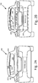
- Figure 2A is a rear view of motor vehicle 200 showing exterior light array 220 as a brake light array of motor vehicle 200, according to one implementation.
- Figure 2A shows rear end 204 and roof 206 of motor vehicle 200, as well as exterior light array 220 (hereinafter “brake light array 220") including multiple lighting elements 218.
- brake light array 220 is situated proximate to or on rear window 208 of motor vehicle 200.
- brake light array 220 is implemented as a center high mounted stop lamp (CHMSL).
- CHMSL center high mounted stop lamp
- first end 222 and second end 224 of brake light array 220 are well as battery 212 of motor vehicle 200.
- Motor vehicle 200 including rear end 204, roof 206, rear window 208, and brake light array 220 corresponds in general to motor vehicle 100, in Figure 1 , and those corresponding features may share any of the characteristics attributed to either corresponding feature in the present disclosure. That is to say, although not shown in Figure 1 , motor vehicle 100 may include features corresponding respectively to rear window 208 and brake light array 220. Moreover, although not shown in Figure 2A , motor vehicle 200 may include features corresponding respectively to front end 102, optional fuel tank 114, and exterior light arrays 116a and 116b. In addition, like motor vehicle 110, motor vehicle 210 may be capable of wireless communication with a remote electronic device corresponding to either or both of key fob 110a and mobile phone 110b, in Figure 1 .
- Battery 212 corresponds in general to battery 112, in Figure 1 , and those corresponding features may share any of the characteristics attributed to either corresponding feature in the present disclosure.
- battery 212 may be implemented as a high voltage battery pack including multiple NiMH, molten-salt, or lithium-ion battery cells, for example, and capable of generating hundreds of volts.
- Lighting elements 218, in Figure 2A can correspond in general to lighting elements 118, in Figure 1 , and those corresponding features may share any of the characteristics attributed to either corresponding feature in the present disclosure.
- lighting elements 218 may be implemented using LEDs.
- brake light array 220 provides brake lighting. Consequently, the color produced by lighting elements 118/218 when illuminated may differ depending on whether they are included in exterior light arrays 116a and 116b, or brake light array 220.
- lighting elements 218 of brake light array 220 may emit red light when illuminated
- lighting elements 118 of exterior light arrays 116a and 116b may emit substantially white or amber light when illuminated, for example.
- Figure 2B shows motor vehicle 100/200 utilizing SOC display system 230 to display the SOC of battery 112/212 of motor vehicle 110/210 by brake light array 220, according to one implementation. It is noted that features identified by reference numbers identical to those shown in Figure 2A correspond respectively to those previously described features. It is further noted that not all features common to Figures 2A and 2B are identified by reference numbers in both figures. For example, in the interests of clarity, respective first and second ends 222 and 224 of brake light array 220 are present in both Figures 2A and 2B , but are identified by reference numbers 222 and 224 only in Figure 2A .
- SOC display system 230 utilized in the exemplary implementation shown in Figure 2B includes battery 112/212, SOC module 240, which is described in greater detail below, and brake light array 220.
- SOC display system 230 may include battery 112/212, fuel tank 114, SOC module 240, and brake light array 220.
- SOC display system 230 may include fuel tank 114 and/or battery 112/212, SOC module 240, and one or both of exterior light arrays 116a and 116b.
- SOC display system 230 including battery 112/212, SOC module 240, and brake light array 220 enables display of the SOC of battery 112/212 using brake light array 220.
- brake light array 220 when brake light array 220 is used during braking, substantially all lighting elements 218 of brake light array 220 are concurrently illuminated, as shown in Figure 2A .
- brake light array 220 when brake light array 220 is used by SOC display system 230 including SOC module 240 to display the SOC of battery 112/212, a subset of lighting elements 218 of brake light array 220 corresponding to the SOC of battery 112/212 is illuminated.
- a subset of lighting elements 218 corresponding to the percent SOC of battery 112/212 may be illuminated, beginning at first end 222 of brake light array 220 and extending toward second end 224 as far as intermediate lighting element 226.
- lighting elements 218 situated between intermediate lighting element 226 and second end 224 of brake light array 220 may remain off while lighting elements 218 from first end 222 of brake light array 220 to intermediate lighting element 226 are illuminated.
- the percentage of the number of lighting elements 218 illuminated to display the SOC of battery 112/212 may substantially match the percent SOC of battery 112/212.
- the SOC of battery 112/212 is 80%
- approximately 80% of sequential lighting elements of lighting elements 118/218 beginning at first end 222 of brake light array 220 may be illuminated to display the SOC of battery 112/212.
- brake light array 220 includes sixty (60) lighting elements 218, for instance, the first 48 of lighting elements 218 of brake light array 220 beginning from first end 222 may be illuminated to display an 80% SOC of battery 112/212.
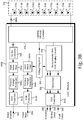
- FIG 3A shows exemplary SOC module 340A and exterior light array 320 suitable for use as part of SOC display system 230, in Figure 2B , according to one implementation.
- SOC module 340A corresponds in general to SOC module 240, and those corresponding features may share any of the characteristics attributed to either corresponding feature by the present disclosure.
- Exterior light array 320 including lighting elements 318a, 318b, 318c, 318d, 318e, 318f, 318g, 318h, 318i, and 318j (hereinafter "lighting elements 318a-318j") is shown and will be described as corresponding to brake light array 220, in Figures 2A and 2B , in the interest of clarity.
- exterior light array 320 can correspond to any of exterior light arrays 116a or 116b, or brake light array 220.
- each of lighting elements 318a-318j may represent multiple individual lighting elements 118/218.
- each of lighting elements 318a-318j may correspond to from 5 to 10 LED lights.
- SOC module 240/340A may receive inputs in the form of brake override signal 332, power input 334, activation signal 336, and battery status signal 338.
- Brake override signal 332 is generated when a braking system of motor vehicle 100/200 is activated, for example, when an operator of motor vehicle 100/200 applies the brakes of motor vehicle 100/200.
- Brake override signal 332 is received by electrostatic discharge (ESD) protection block 342a of SOC module 240/340A, and further passes through reverse voltage protection block 344a, input noise filter 346a, and DC/DC converter 348, before being provided as an input to lighting element controller 358.
- ESD electrostatic discharge
- Power input 334 provides power for energizing various components of SOC module 240/340A, such as microcontroller unit 356, which may serve as the SOC display controller of SOC module 240/340A, and lighting element controller 358, which controls the illumination of lighting elements 318a-318j.
- Power input 334 is received by ESD protection block 342b, and further passes through reverse voltage protection block 344b, input noise filter 346b, and voltage regulator 352, which may be a low-dropout regulator, for example, before being provided as an input to each of microcontroller unit 356 and lighting element controller 358.
- Activation signal 336 and battery status signal 338 are used by microcontroller unit 356 and lighting element controller 358 to generate display signal 386a.
- Display signal 386a causes some or all of lighting elements 318a-318j (shown as 218 in Figures 2A and 2B ) to be illuminated for displaying the SOC of battery 112/212 by exterior light array/brake light array 320 (hereinafter "brake light array 320").
- activation signal 336 and battery status signal 338 are received by microcontroller unit 356 via ESD protection block 342c and transceiver 350. It is noted that, in various implementations, activation signal 336 and battery status signal 338 may be received as wired or wireless inputs to SOC module 240/340A.
- display signal 386a is generated and provided as an output by SOC module 240/340A based on activation signal 336 and battery status signal 338.
- Battery status signal 338 includes the SOC of battery 112/212 and may be received by SOC module 240/340A from battery 112/212 of motor vehicle 100/200.
- Activation signal 336 may be generated in a number of different ways. For example, activation signal 336 may be generated automatically when motor vehicle 100/200 including SOC display system 230 is plugged in to an external source of electric power. Alternatively, or in addition, activation signal 336 may be generated in response to a wireless signal received from remote electronic device 110a or 110b. That is to say, in some implementations, activation signal 336 may be generated in response to a wireless signal received from key fob 110a of motor vehicle 100/200, or from mobile phone 110b.
- activation signal 336 is generated in response to a wireless signal received from remote electronic device 110a or 110b
- that wireless signal may be received due to a manual input to remote electronic device 110a or 110b by a user in possession of remote electronic device 110a or 110b.
- the wireless signal to which generation of activation signal 336 is responsive may be received automatically from remote electronic device 110a or 110b, due to proximity of remote electronic device 110a or 110b to motor vehicle 100/200.
- Lighting element controller 358 of SOC module 240/340A provides display signal 386a as an output causing some or all of lighting elements 318a-318j (shown as 218 in Figures 2A and 2B ) to be selectively illuminated. It is emphasized, however, that brake override signal 332 has preferential control over display signal 386a. As a result, lighting element controller 358 is configured to preferentially provide brake override signal 332 for illuminating substantially all of lighting elements 318a-318j (shown as 218 in Figures 2A and 2B ), as an output to brake light array 220/320, through display signal 386a, in response to receiving brake override signal 332 with or without power input 334.
- FIG. 3B shows exemplary SOC module 340B and brake light array 320 suitable for use as part of SOC display system 230, in Figure 2B , according to another implementation.
- SOC module 340B corresponds in general to SOC module 240, in Figure 2 , and those corresponding features may share any of the characteristics attributed to either corresponding feature in the present disclosure.
- the features of SOC module 340B identified by reference numbers identical to those shown in Figure 3A correspond respectively to those previously described features and may share any of the characteristics attributed to those corresponding features in the present disclosure.
- brake light array 320 the array of lighting elements 318a-318j is described as brake light array 320 in the interest of clarity, in other implementations, the functionality attributed to brake light array 320 may be provided by exterior light array 116a and/or 116b, in Figure 1 .
- exemplary SOC module 240/340B is shown to receive an additional input in the form of fuel status signal 388.
- fuel status signal 388 is received by SOC module 240/340B via ESD protection block 342c and transceiver 350, and may be received as a wired or wireless input to SOC module 240/340B.
- Fuel status signal 388 may be received from optional fuel tank 114 of motor vehicle 100/200, and may correspond to a fuel supply in fuel tank 114.
- Microcontroller unit 356 of SOC module 240/340B receives activation signal 336, battery status signal 338, and fuel status signal 388 from transceiver 350.
- display signal 386b is generated and provided as an output by SOC module 240/340B based on activation signal 336, battery status signal 338, and fuel status signal 388.
- Display signal 386b causes some of lighting elements 318a-318j (shown as 218 in Figures 2A and 2B ) to be illuminated for displaying the SOC of battery 112/212 by brake light array 320.
- display signal 386b causes some others of lighting elements 318a-318j (shown as 218 in Figures 2A and 2B ) to be illuminated for displaying the fuel supply of fuel tank 114 by brake light array 320.
- a first subset of lighting elements 218/318a-318j including half of those lighting elements e.g., lighting elements 318a, 318b, 318c, 318d, and 318e (hereinafter “lighting elements 318a-318e”) may be used to display the SOC of battery 112/212.
- a second subset of lighting elements 218/318a-318j including the other half of those lighting elements e.g., lighting elements 318f, 318g, 318h, 318i, and 318j (hereinafter “lighting elements 318f-318j"
- lighting elements 318f-318j may be used to display the fuel supply of fuel tank 114.
- display signal 386b provided as an output from SOC module 240/340B causes some or all of first subset of lighting elements 318a-318e to be selectively illuminated to display the SOC of battery 112/212.
- Display signal 386b also causes some or all of second subset of lighting elements 318f-318j to be selectively illuminated to display the fuel supply of fuel tank 114. It is emphasized, however, that brake override signal 332 has preferential control over display signal 386b.
- lighting element controller 358 is configured to preferentially provide brake override signal 332 for illuminating substantially all of lighting elements 218/318a-318j, as an output brake light array 220/320, through display signal 386b, in response to receiving brake override signal 332 with or without power input 334.
- Figure 4A shows lighting element illumination patterns provided by SOC display system 230, in Figure 2 , during various display modes, while Figure 4B shows SOC illumination patterns provided by that system during an SOC display stage, according to one implementation.
- Table 400A of Figure 4A and table 400B of Figure 4B show lighting element illumination patterns displayed by brake light array 420 in response to different SOC display criteria.
- those SOC display criteria can include no display mode 460a resulting in non-illumination pattern 460b, and mode 462a corresponding to an initiation stage immediately following plug in (also referred to as "immediate plug-in recognition mode"), or to a plug in state in which the external source of electric power is not charging the battery due to scheduling criteria or the external source being offline, resulting in illumination pattern 462b.
- the display criteria shown by table 400A includes SOC display mode 464, which can result in illumination patterns corresponding to the measured SOC of the battery and represented in table 400A by exemplary 80% SOC illumination pattern 466h.
- charging fault mode 468a in which motor vehicle 100/200 is plugged in to an external source of electric power but not charging properly, resulting in illumination pattern 468b.
- the SOC display criteria can include a variety of SOC charge states 464a, 464b, 464c, 464d, 464e, 464f, 464g, 464h, 464i, and 464j (hereinafter "SOC charge states 46aa-464j") in which motor vehicle 100/200 including battery 112/212 is plugged in to an external source of electric power.
- SOC charge states 46aa-464j SOC charge states 46aa-464j
- table 400B shows SOC illumination patterns 466a, 466b, 466c, 466d, 466e, 466f, 466g, 466h, 466i, and 466j (hereinafter "SOC illumination patterns 466a-466j") corresponding respectively to SOC charge states 464a-464j.
- Figure 4A also shows activation signal 436 for display modes 460a, 462a, 464, and 468a.
- Activation signal 436 in Figure 4A , corresponds in general to activation signal 336, in Figures 3A and 3B , and may share any of the characteristics attributed to that corresponding feature in the present disclosure.
- activation signal 336/436 has a low or substantially zero value for no display mode 460a, resulting in non-illumination pattern 460b.
- activation signal 336/436 has a value of substantially 20% of duty cycle for mode 462a, substantially 30% of duty cycle for SOC display mode 464 (i.e., all of SOC charge states 464a-464j), and substantially 40% of duty cycle for charging fault mode 468a.
- SOC display system 230 indicates that it is in an evaluation mode due to activation signal 436 just being turned on in response to a plug in event or in response to a wireless signal received from a key fob or from a mobile phone being carried by a user. While evaluation is in progress, only the central few lighting elements 218/318a-318j are illuminated, as shown by illumination pattern 462b in Figure 4A , to indicate that SOC display system 230 is in an evaluation or initiation mode.
- lighting elements 218/318a-318j may be illuminated according to the actual SOC of the battery, i.e. transition may be made to one of the SOC illumination patterns 466a-466j or to fault illumination pattern 468b displayed by brake light array 220/320/420.
- illumination pattern 462b persists after the initiation stage.
- the initiation stage of the SOC display system may last approximately ten seconds before transition is made to one of SOC illumination patterns 466a-466j or fault illumination pattern 468b displayed by brake light array 220/320/420.
- illumination pattern 462b, SOC illumination patterns 466a-466j, or fault illumination pattern 468b displayed by brake light array 220/320/420 remain on for only a predetermined amount of time, such as 45 seconds or a few minutes, and then turn off until the next SOC illumination pattern needs to be displayed (for example, to show an increase in the percentage of battery charge) or unless turned on again by user demand (such as use of the key fob or the mobile phone).
- illumination pattern 462b, SOC illumination patterns 466a-466j, or fault illumination pattern 468b displayed by brake light array 220/320/420 remain on for as long as the vehicle is plugged in.
- Brake light array 420 in Figures 4A and 4B , corresponds in general to brake light array 220/320 in Figures 2A, 2B , 3A , and 3B , and those corresponding features may share the characteristics attributed to any of the corresponding features in the present disclosure.
- the exemplary lighting element illumination patterns shown in Figures 4A and 4B correspond to implementations of SOC display system 230 in which SOC module 240 takes the form of SOC module 340A, shown in Figure 3A .
- the exemplary lighting element illumination patterns displayed by SOC display system 230 during the SOC display stage shown in Figure 4B display the SOC of battery 112/212 by brake light array 220/320/420, but not the fuel supply of fuel tank 114.
- the same illumination pattern i.e., illumination pattern 462b
- illumination pattern 462b is shown for all SOC display criteria with the exception of no display 460a. That is to say, no display SOC display criterion 460a results in non-illumination pattern 460b of lighting elements 218/318a-318j. All other SOC display criteria, i.e., SOC charge states 464a-464j and a fault state result in display of illumination pattern 462b in which only a central subset of lighting elements 218/318a-318j are illuminated during the initiation stage of SOC display system 230.
- illumination pattern 462b may include illumination of a central 20% of lighting elements 218/318a-318j during the initiation stage. Referring to Figure 3A , for instance, illumination pattern 462b may result in lighting elements 318e and 318f being illuminated, while lighting elements 318a, 318b, 318c, 318d, 318g, 318h, 318i, and 318j are off.
- illumination pattern 462b may correspond uniquely to mode 462a during the SOC display stage, while all other SOC display criteria, i.e., SOC charge states 464a-464j and charging fault mode 468a result in different respective illumination patterns.
- SOC charge state 464a is shown to correspond to a 10% SOC of battery 112/212 during charging.
- SOC illumination pattern 466a for SOC charge state 464a during the SOC display stage of SOC display system 230 results in approximately 10% of lighting elements 218/318a-318j being illuminated.
- SOC illumination pattern 466a may include illumination of approximately 10% of consecutive lighting elements of lighting elements 218/318a-318j, beginning at first end 222 of brake light array 220/320, during the SOC display stage.
- SOC illumination pattern 466a may result in lighting element 318a being illuminated, while lighting elements 318b, 318c, 318d, 318e, 318f, 318g, 318h, 318i, and 318j are off.
- SOC charge state 464b is shown to correspond to a 20% SOC of battery 112/212 during charging.
- SOC illumination pattern 466b for SOC charge state 464b during the SOC display stage of SOC display system 230 results in approximately 20% of lighting elements 218/318a-318j being illuminated.
- SOC illumination pattern 466b may include illumination of approximately 20% of consecutive lighting elements of lighting elements 218/318a-318j, beginning at first end 222 of brake light array 220/320, during the SOC display stage.
- SOC illumination pattern 466b may result in lighting elements 318a and 318b being illuminated, while lighting elements 318c, 318d, 318e, 318f, 318g, 318h, 318i, and 318j are off.
- SOC charge state 464c is shown to correspond to a 30% SOC of battery 112/212 during charging.
- SOC illumination pattern 466c for SOC charge state 464c during the SOC display stage of SOC display system 230 results in approximately 30% of lighting elements 218/318a-318j being illuminated.
- SOC illumination pattern 466c may include illumination of approximately 30% of consecutive lighting elements of lighting elements 218/318a-318j, beginning at first end 222 of brake light array 220/320, during the SOC display stage.
- SOC illumination pattern 466c may result in lighting elements 318a, 318b, and 318c being illuminated, while lighting elements 318d, 318e, 318f, 318g, 318h, 318i, and 318j are off.
- SOC charge state 464d is shown to correspond to a 40% SOC of battery 112/212 during charging.
- SOC illumination pattern 466d for SOC charge state 464d during the SOC display stage of SOC display system 230 results in approximately 40% of lighting elements 218/318a-318j being illuminated.
- SOC illumination pattern 466d may include illumination of approximately 40% of consecutive lighting elements of lighting elements 218/318a-318j, beginning at first end 222 of brake light array 220/320, during the SOC display stage.
- SOC illumination pattern 466d may result in lighting elements 318a, 318b, 318c, and 318d being illuminated, while lighting elements 318e, 318f, 318g, 318h, 318i, and 318j are off.
- SOC charge state 464e is shown to correspond to a 50% SOC of battery 112/212 during charging.
- SOC illumination pattern 466e for SOC charge state 464e during the SOC display stage of SOC display system 230 results in approximately 50% of lighting elements 218/318a-318j being illuminated.
- SOC illumination pattern 466e may include illumination of approximately 50% of consecutive lighting elements of lighting elements 218/318a-318j, beginning at first end 222 of brake light array 220/320, during the SOC display stage.
- SOC illumination pattern 466e may result in lighting elements 318a, 318b, 318c, 318d, and 318e being illuminated, while lighting elements 318f, 318g, 318h, 318i, and 318j are off.
- SOC charge state 464f is shown to correspond to a 60% SOC of battery 112/212 during charging.
- SOC illumination pattern 466f for SOC charge state 464f during the SOC display stage of SOC display system 230 results in approximately 60% of lighting elements 218/318a-318j being illuminated.
- SOC illumination pattern 466f may include illumination of approximately 60% of consecutive lighting elements of lighting elements 218/318a-318j, beginning at first end 222 of brake light array 220/320, during the SOC display stage.
- SOC illumination pattern 466f may result in lighting elements 318a, 318b, 318c, 318d, 318e, and 318f being illuminated, while lighting elements 318g, 318h, 318i, and 318j are off.
- SOC charge state 464g is shown to correspond to a 70% SOC of battery 112/212 during charging.
- SOC illumination pattern 466g for SOC charge state 464g during the SOC display stage of SOC display system 230 results in approximately 70% of lighting elements 218/318a-318j being illuminated.
- SOC illumination pattern 466g may include illumination of approximately 70% of consecutive lighting elements of lighting elements 218/318a-318j, beginning at first end 222 of brake light array 220/320, during the SOC display stage.
- SOC illumination pattern 466f may result in lighting elements 318a, 318b, 318c, 318d, 318e, 318f, and 318g being illuminated, while lighting elements 318h, 318i, and 318j are off.
- SOC charge state 464h is shown to correspond to an 80% SOC of battery 112/212 during charging.
- SOC illumination pattern 466h for SOC charge state 464h during the SOC display stage of SOC display system 230 results in approximately 80% of lighting elements 218/318a-318j being illuminated.
- SOC illumination pattern 466h may include illumination of approximately 80% of consecutive lighting elements of lighting elements 218/318a-318j, beginning at first end 222 of brake light array 220/320, during the SOC display stage.
- SOC illumination pattern 466h may result in lighting elements 318a, 318b, 318c, 318d, 318e, 318f, 318g, and 318h being illuminated, while lighting elements 318i and 318j are off.
- SOC charge state 464i is shown to correspond to a 90% SOC of battery 112/212 during charging.
- SOC illumination pattern 466i for SOC charge state 464i during the SOC display stage of SOC display system 230 results in approximately 90% of lighting elements 218/318a-318j being illuminated.
- SOC illumination pattern 466i may include illumination of approximately 90% of consecutive lighting elements of lighting elements 218/318a-318j, beginning at first end 222 of brake light array 220/320, during the SOC display stage.
- SOC illumination pattern 466i may result in lighting elements 318a, 318b, 318c, 318d, 318e, 318f, 318g, 318h, and 318i being illuminated, while lighting element 318j is off.
- SOC charge state 464j is shown to correspond to a 100% SOC of battery 112/212 during charging.
- SOC illumination pattern 466j for SOC charge state 464j during the SOC display stage of SOC display system 230 results in substantially 100% of lighting elements 218/318a-318j being illuminated.
- SOC illumination pattern 466j may include illumination of substantially 100% of consecutive lighting elements of lighting elements 218/318a-318j, beginning at first end 222 of brake light array 220/320, during the SOC display stage. Referring to Figure 3A , for instance, SOC illumination pattern 466j may result in all of lighting elements 318a-318j being illuminated.
- Charging fault mode 468a is shown to correspond to a fault state during charging of battery 112/212.
- Fault illumination pattern 468b for fault mode 468a during the SOC display stage of SOC display system 230 results in lighting elements 218/318a-318j being illuminated in a non-continuous pattern.
- fault illumination pattern 468b may include illumination of sequences of approximately 10% of consecutive lighting elements of lighting elements 218/318a-318j alternating with sequences of approximately 10% of consecutive lighting elements of lighting elements 218/318a-318j that are off during the SOC display stage.
- fault illumination pattern 468b may result in alternate lighting elements 318a, 318c, 318e, 318g, and 318i being illuminated, while intervening alternate lighting elements 318b, 318d, 318f, 318h, and 318j are off.
- SOC display system 230 indicates that it is in an evaluation mode due to activation signal 336/436 just being turned on in response to a plug in event or in response to a wireless signal received from a key fob or from a mobile phone being carried by a user. While evaluation is in progress, only the central few lighting elements 218/318a-318j are illuminated as shown in Figure 4A to indicate that the SOC display system is in an evaluation or initiation mode. After passage of a predetermined period of time, such as several seconds, when evaluation of SOC of the battery is complete, lighting elements 218/318a-318j are illuminated according to the actual SOC of the battery, i.e. transition is made to one of SOC illumination patterns 466a-466j, or fault illumination pattern 468b is displayed, or illumination pattern 462b continues to be displayed by brake light array 220/320/420.
- a predetermined period of time such as several seconds
- the initiation stage of the SOC display system may last approximately ten seconds, during which time illumination pattern 462b is displayed. After the initiation stage, e.g., after ten second, illumination pattern 462b may continue to be displayed, or transition may be made to one of SOC illumination patterns 466a-466j or fault illumination pattern 468b.
- illumination pattern 462b, SOC illumination patterns 466a-466j, or fault illumination pattern 468b displayed by brake light array 220/320/420 remain on for only a predetermined amount of time, such as 45 seconds or a few minutes, and then turn off until the next SOC illumination pattern needs be displayed (for example, to show an increase in the percentage of battery charge) or unless turned on again by user demand (such as use of the key fob or the mobile phone).
- illumination pattern 462b, SOC illumination patterns 466a-466j, or fault illumination pattern 468b displayed by brake light array 220/320/420 remain on for as long as the vehicle is plugged in.
- the present application addresses the inconvenience to all-electric and plug-in hybrid motor vehicle owners and operators imposed by conventional solutions for displaying the SOC of a battery of the motor vehicle during charging.
- the present solution advantageously enables the motor vehicle owner or operator to view the SOC from a distance of many meters, such as tens of meters, for example.
- the present solution further advantageously enables display of the SOC of the battery on demand.
Landscapes
- Engineering & Computer Science (AREA)
- Mechanical Engineering (AREA)
- Transportation (AREA)
- Chemical & Material Sciences (AREA)
- Combustion & Propulsion (AREA)
- Life Sciences & Earth Sciences (AREA)
- Sustainable Development (AREA)
- Sustainable Energy (AREA)
- Power Engineering (AREA)
- Lighting Device Outwards From Vehicle And Optical Signal (AREA)
- Electric Propulsion And Braking For Vehicles (AREA)
- Charge And Discharge Circuits For Batteries Or The Like (AREA)
Claims (11)
- Ladezustands-, SOC-, Anzeigesystem (230), umfassend:eine Batterie (112; 212);eine Bremslichtanordnung (220; 320; 420), die mehrere Leuchtelemente (218; 318a-318j) beinhaltet; undein SOC-Modul (240; 340B), das dazu ausgelegt ist:ein Batteriezustandssignal (338) zu empfangen, wobei das Batteriezustandssignal (338) einen SOC der Batterie (112; 212) beinhaltet;ein Kraftstoffzustandssignal (388) eines Kraftstofftanks (114) zu empfangen, wobei das Kraftstoffzustandssignal (388) einer Kraftstoffversorgung in dem Kraftstofftank (114) entspricht; undein Anzeigesignal (386b) an die Bremslichtanordnung (220; 320; 420) auszugeben, basierend auf dem Batteriezustandssignal (338) und dem Kraftstoffzustandssignal (388);wobei die Bremslichtanordnung (220; 320; 420) dazu ausgelegt ist:das Anzeigesignal (386b) von dem SOC-Modul (240; 340B) zu empfangen;eine erste Untergruppe der mehreren Leuchtelemente (218; 318a-318j) zum Anzeigen des SOC der Batterie (112; 212) durch die Bremslichtanordnung (220; 320; 420) als Reaktion auf das Anzeigesignal (386b) zu beleuchten; undBeleuchten einer zweiten Untergruppe der mehreren Leuchtelemente (218; 318a-318j) zum Anzeigen der Kraftstoffversorgung durch die Bremslichtanordnung (220; 320; 420) als Reaktion auf das Anzeigesignal (386b).
- SOC-Anzeigesystem (230) nach Anspruch 1, wobei die mehreren Leuchtelemente (218; 318a-318j) lichtemittierende Dioden, LEDs, umfassen.
- SOC-Anzeigesystem (230) nach einem der vorhergehenden Ansprüche, wobei ein SOC-Aktivierungssignal erzeugt wird, um das SOC-Modul (240; 2340B) zu aktivieren
wenn ein Kraftfahrzeug (100; 200), das das SOC-Anzeigesystem (230) beinhaltet, an eine externe elektrische Energiequelle zum Laden der Batterie (112; 212) angeschlossen ist und/oder
als Reaktion auf ein drahtloses Signal, das von einer entfernten elektronischen Vorrichtung (110a; 110b) empfangen wird, wobei die entfernte elektronische Vorrichtung (110a; 110b) insbesondere ein Schlüsselanhänger oder ein Mobiltelefon ist. - SOC-Anzeigesystem (230) nach einem der vorhergehenden Ansprüche, wobei das SOC-Modul (240; 340B) ferner dazu ausgelegt ist, die Untergruppe der mehreren Leuchtelemente (218; 318a-318j) nach einem vorbestimmten Zeitintervall abzuschalten.
- Kraftfahrzeug (100; 200), umfassend:einen Kraftstofftank (114); unddas SOC-Anzeigesystem (230) nach Anspruch 1.
- Kraftfahrzeug (100; 200) nach Anspruch 5, wobei die Bremslichtanordnung in der Nähe oder auf einer Heckscheibe eines Kraftfahrzeugs angeordnet ist und/oder eine hochmontierte mittlere Bremsleuchte (CHMSL) umfasst.
- Kraftfahrzeug (100; 200) nach Anspruch 5 oder 6, wobei die mehreren Leuchtelemente (218; 318a-318j) lichtemittierende Dioden, LEDs, umfassen.
- Kraftfahrzeug (100; 200) nach einem der Ansprüche 5 bis 7, wobei ein SOC-Aktivierungssignal erzeugt wird, um das SOC-Modul (240; 340B) zu aktivieren
wenn das Kraftfahrzeug (100; 200) an eine externe elektrische Energiequelle zum Laden der Batterie (112; 212) angeschlossen ist und/oder
als Reaktion auf ein drahtloses Signal, das von einer entfernten elektronischen Vorrichtung (110a; 110b) empfangen wird, wobei die entfernte elektronische Vorrichtung (110a; 110b) insbesondere ein Schlüsselanhänger oder ein Mobiltelefon ist. - Kraftfahrzeug nach einem der Ansprüche 5 bis 8, wobei das SOC-Modul (240; 340B) ferner dazu ausgelegt ist, die erste und zweite Untergruppe der mehreren Leuchtelemente (218; 318a-318j) nach einem vorbestimmten Zeitintervall abzuschalten.
- Verfahren zur Verwendung durch ein Ladezustands-, SOC-Anzeigesystem (230) eines Kraftfahrzeugs (100; 200), das eine Batterie (112; 212), einen Kraftstofftank (114) und eine Bremslichtanordnung (220, 320; 420) mit mehreren Leuchtelementen (218; 318a-318j) beinhaltet, wobei das Verfahren umfasst:Empfangen eines Batteriezustandssignals (338) von der Batterie (112; 212) zu empfangen, wobei das Batteriezustandssignal (338) einen SOC der Batterie beinhaltet;Empfangen eines Kraftstoffzustandssignals (388) des Kraftstofftanks (114), wobei das Kraftstoffzustandssignal (388) einer Kraftstoffversorgung in dem Kraftstofftank (114) entspricht;Ausgeben eines Anzeigesignals (386b) an die Bremslichtanordnung (220; 320; 420), basierend auf dem Batteriezustandssignal (338) und dem Kraftstoffzustandssignal (388);Beleuchten einer ersten Untergruppe der mehreren Leuchtelemente (218; 318a-318j) zum Anzeigen des SOC der Batterie (112; 212) durch die Bremslichtanordnung (220; 320; 420) als Reaktion auf das Anzeigesignal (386b); und Beleuchten einer zweiten Untergruppe der mehreren Leuchtelemente (218; 318a-318j) zum Anzeigen der Kraftstoffversorgung durch die Bremslichtanordnung (220; 320; 420) als Reaktion auf das Anzeigesignal (386b).
- Verfahren nach Anspruch 10, ferner umfassend:Aktivieren des SOC-Anzeigesystems (230), wenn das Kraftfahrzeug (100; 200) an eine externe elektrische Energiequelle zum Laden der Batterie (112; 212) angeschlossen ist und/oderAktivieren des SOC-Anzeigesystems (230) als Reaktion auf ein drahtloses Signal, das von einer entfernten elektronischen Vorrichtung (110a; 110b) empfangen wird.
Applications Claiming Priority (1)
| Application Number | Priority Date | Filing Date | Title |
|---|---|---|---|
| US15/883,397 US11173805B2 (en) | 2018-01-30 | 2018-01-30 | State-of-charge display system |
Publications (2)
| Publication Number | Publication Date |
|---|---|
| EP3517339A1 EP3517339A1 (de) | 2019-07-31 |
| EP3517339B1 true EP3517339B1 (de) | 2021-08-25 |
Family
ID=65036697
Family Applications (1)
| Application Number | Title | Priority Date | Filing Date |
|---|---|---|---|
| EP19152339.8A Active EP3517339B1 (de) | 2018-01-30 | 2019-01-17 | Ladezustandsanzeigesystem |
Country Status (3)
| Country | Link |
|---|---|
| US (1) | US11173805B2 (de) |
| EP (1) | EP3517339B1 (de) |
| CN (1) | CN110091716A (de) |
Families Citing this family (12)
| Publication number | Priority date | Publication date | Assignee | Title |
|---|---|---|---|---|
| TWI897843B (zh) * | 2017-05-03 | 2025-09-21 | 美商必治妥美雅史谷比公司 | 結合至肌肉生長抑制素以纖維連接蛋白為主之支架結構域蛋白質的穩定調配物 |
| JP7027946B2 (ja) * | 2018-02-22 | 2022-03-02 | トヨタ自動車株式会社 | 車両 |
| CN112424019B (zh) * | 2018-06-29 | 2024-06-04 | 瑞维安知识产权控股有限责任公司 | 外部灯和充电指示器 |
| US11580798B2 (en) | 2020-08-27 | 2023-02-14 | Nissan North America, Inc. | Vehicle lighting system |
| CN112677764B (zh) * | 2020-12-31 | 2022-06-21 | 北京国家新能源汽车技术创新中心有限公司 | 车辆显示soc的方法及车辆 |
| US11945329B2 (en) * | 2022-05-02 | 2024-04-02 | GM Global Technology Operations LLC | Intelligent vehicle systems and control logic for battery charge control and information display |
| FR3139631A1 (fr) * | 2022-09-14 | 2024-03-15 | Psa Automobiles Sa | Indication du niveau de charge batterie par l’éclairage de l’intérieur du véhicule |
| GB2624622A (en) * | 2022-11-15 | 2024-05-29 | Mercedes Benz Group Ag | A method for indicating a charging level of an electric storage device of an at least partially electrically operated motor vehicle, computer program produc |
| FR3141916A1 (fr) * | 2022-11-15 | 2024-05-17 | Renault S.A.S | Capot avant de vehicule automobile equipe d’un indicateur de charge electrique du vehicule |
| US12293618B2 (en) * | 2023-08-11 | 2025-05-06 | GM Global Technology Operations LLC | Method of providing information related to status of electric vehicle |
| US12400495B2 (en) | 2023-08-11 | 2025-08-26 | GM Global Technology Operations LLC | Method of providing information related to status of electric vehicle |
| US12565118B2 (en) | 2023-08-11 | 2026-03-03 | GM Global Technology Operations LLC | Method of providing information when an electric vehicle is used as a battery pack |
Family Cites Families (15)
| Publication number | Priority date | Publication date | Assignee | Title |
|---|---|---|---|---|
| TW300957B (de) * | 1994-11-21 | 1997-03-21 | Seiko Epson Corp | |
| JP3716619B2 (ja) * | 1998-05-14 | 2005-11-16 | 日産自動車株式会社 | 電池の残容量計 |
| US6784641B2 (en) * | 2000-09-20 | 2004-08-31 | Toshiba Battery Co., Ltd. | Uninterruptible power supply |
| KR100879515B1 (ko) * | 2006-11-09 | 2009-01-22 | 삼성전자주식회사 | 휴대용 단말기의 배터리 충전상태 표시방법 및 장치 |
| JP2011517143A (ja) * | 2008-01-09 | 2011-05-26 | ジョンソン コントロールズ テクノロジー カンパニー | 車両システムと相互作用する双方向携帯型電子装置 |
| US8125186B2 (en) * | 2008-06-16 | 2012-02-28 | Steve Carkner | Graphic state of charge indicator for a battery charging system and method of use |
| US8606430B2 (en) * | 2010-10-08 | 2013-12-10 | GM Global Technology Operations LLC | External presentation of information on full glass display |
| CN103260932B (zh) * | 2010-10-14 | 2016-05-18 | 丰田自动车株式会社 | 电动车辆的显示系统及具备该显示系统的电动车辆 |
| US20120133282A1 (en) * | 2010-11-30 | 2012-05-31 | Aptera Motors, Inc. | External state of charge indicator system for an automotive vehicle |
| US20130307550A1 (en) * | 2012-05-18 | 2013-11-21 | O2Micro Inc. | State of charge indicators for battery packs |
| US20140253306A1 (en) * | 2013-03-06 | 2014-09-11 | Ford Global Technologies, Llc | Electric Vehicle State of Charge Indicator Integrated With Exterior Lamps |
| US20140301101A1 (en) * | 2013-04-07 | 2014-10-09 | Mr. Derek Terrell Russ | Multifunctional Multiple Color Center High Mounted Stop Lamp |
| DE102014222695A1 (de) | 2014-04-16 | 2015-10-22 | Volkswagen Aktiengesellschaft | Anzeigen eines Ladevorgangs eines elektrischen Energiespeichers eines Fahrzeugs |
| JP6185945B2 (ja) * | 2015-02-23 | 2017-08-23 | 株式会社Subaru | ハイブリッド車両のsoc表示装置 |
| US10240542B1 (en) * | 2017-11-20 | 2019-03-26 | Ford Global Technologies, Llc | Methods and systems for fuel system monitoring |
-
2018
- 2018-01-30 US US15/883,397 patent/US11173805B2/en not_active Expired - Fee Related
-
2019
- 2019-01-15 CN CN201910033787.4A patent/CN110091716A/zh active Pending
- 2019-01-17 EP EP19152339.8A patent/EP3517339B1/de active Active
Also Published As
| Publication number | Publication date |
|---|---|
| EP3517339A1 (de) | 2019-07-31 |
| CN110091716A (zh) | 2019-08-06 |
| US20190232795A1 (en) | 2019-08-01 |
| US11173805B2 (en) | 2021-11-16 |
Similar Documents
| Publication | Publication Date | Title |
|---|---|---|
| EP3517339B1 (de) | Ladezustandsanzeigesystem | |
| US8742907B2 (en) | Electric power information provision apparatus for an electric vehicle | |
| US7999665B2 (en) | Plug-in vehicle having a recharging port with a state of charge indicator | |
| CN103303188B (zh) | 控制车辆照明的系统和方法 | |
| US7047120B2 (en) | Vehicle and method for controlling brake system indicators | |
| US20140253306A1 (en) | Electric Vehicle State of Charge Indicator Integrated With Exterior Lamps | |
| US7256514B2 (en) | Device and method for operating an electrical machine for a motor vehicle | |
| CN108422863B (zh) | 光控制装置及其车辆和用于控制车辆的方法 | |
| US10427545B2 (en) | Electric vehicle supply equipment (EVSE) fault indicator systems | |
| EP3573861A1 (de) | Vorrichtung zur steuerung einer lichtquellenanordnung für die innenbeleuchtung eines passagierraums eines kraftfahrzeugs | |
| US20140232179A1 (en) | Vehicle and method of controlling vehicle | |
| US20190329656A1 (en) | Auxiliary battery charging systems and methods for electrified vehicles | |
| KR20210040500A (ko) | 전기 모터를 구비한 자동차 및 그를 위한 충전 상태 표시 방법 | |
| GB2510124A (en) | Electric vehicle with externally visible charging indication | |
| US11137122B2 (en) | Vehicle-mounted illumination device | |
| JP2017192172A (ja) | 充電状態表示装置 | |
| KR100598875B1 (ko) | 병렬형 하이브리드 전기자동차의 아이들 스톱 제어장치 | |
| US20230123176A1 (en) | Customizable electric vehicle supply equipment systems | |
| US8140208B2 (en) | Electric drive vehicle | |
| US20230030477A1 (en) | Vehicle control unit and vehicle control system | |
| KR101289052B1 (ko) | 저전압 배터리를 이용한 전기구동식 농용 작업차의 시동 제어 시스템 | |
| CN111845628A (zh) | 车载无线充电系统控制方法及控制装置 | |
| US20150298554A1 (en) | Method and device for determining an operating strategy for a range extender of an electric vehicle | |
| EP4124352A1 (de) | Fahrzeugdesinfktionssteuervorrichtung und fahrzeugdesinfktionssteuerverfahren | |
| CN211575064U (zh) | 一种智能充气多功能检修灯 |
Legal Events
| Date | Code | Title | Description |
|---|---|---|---|
| PUAI | Public reference made under article 153(3) epc to a published international application that has entered the european phase |
Free format text: ORIGINAL CODE: 0009012 |
|
| STAA | Information on the status of an ep patent application or granted ep patent |
Free format text: STATUS: THE APPLICATION HAS BEEN PUBLISHED |
|
| AK | Designated contracting states |
Kind code of ref document: A1 Designated state(s): AL AT BE BG CH CY CZ DE DK EE ES FI FR GB GR HR HU IE IS IT LI LT LU LV MC MK MT NL NO PL PT RO RS SE SI SK SM TR |
|
| AX | Request for extension of the european patent |
Extension state: BA ME |
|
| STAA | Information on the status of an ep patent application or granted ep patent |
Free format text: STATUS: REQUEST FOR EXAMINATION WAS MADE |
|
| 17P | Request for examination filed |
Effective date: 20200130 |
|
| RBV | Designated contracting states (corrected) |
Designated state(s): AL AT BE BG CH CY CZ DE DK EE ES FI FR GB GR HR HU IE IS IT LI LT LU LV MC MK MT NL NO PL PT RO RS SE SI SK SM TR |
|
| GRAP | Despatch of communication of intention to grant a patent |
Free format text: ORIGINAL CODE: EPIDOSNIGR1 |
|
| STAA | Information on the status of an ep patent application or granted ep patent |
Free format text: STATUS: GRANT OF PATENT IS INTENDED |
|
| INTG | Intention to grant announced |
Effective date: 20210322 |
|
| GRAS | Grant fee paid |
Free format text: ORIGINAL CODE: EPIDOSNIGR3 |
|
| GRAA | (expected) grant |
Free format text: ORIGINAL CODE: 0009210 |
|
| STAA | Information on the status of an ep patent application or granted ep patent |
Free format text: STATUS: THE PATENT HAS BEEN GRANTED |
|
| AK | Designated contracting states |
Kind code of ref document: B1 Designated state(s): AL AT BE BG CH CY CZ DE DK EE ES FI FR GB GR HR HU IE IS IT LI LT LU LV MC MK MT NL NO PL PT RO RS SE SI SK SM TR |
|
| REG | Reference to a national code |
Ref country code: CH Ref legal event code: EP |
|
| REG | Reference to a national code |
Ref country code: IE Ref legal event code: FG4D Ref country code: AT Ref legal event code: REF Ref document number: 1423452 Country of ref document: AT Kind code of ref document: T Effective date: 20210915 |
|
| REG | Reference to a national code |
Ref country code: DE Ref legal event code: R096 Ref document number: 602019007031 Country of ref document: DE |
|
| REG | Reference to a national code |
Ref country code: LT Ref legal event code: MG9D |
|
| REG | Reference to a national code |
Ref country code: NL Ref legal event code: MP Effective date: 20210825 |
|
| REG | Reference to a national code |
Ref country code: AT Ref legal event code: MK05 Ref document number: 1423452 Country of ref document: AT Kind code of ref document: T Effective date: 20210825 |
|
| PG25 | Lapsed in a contracting state [announced via postgrant information from national office to epo] |
Ref country code: PT Free format text: LAPSE BECAUSE OF FAILURE TO SUBMIT A TRANSLATION OF THE DESCRIPTION OR TO PAY THE FEE WITHIN THE PRESCRIBED TIME-LIMIT Effective date: 20211227 Ref country code: NO Free format text: LAPSE BECAUSE OF FAILURE TO SUBMIT A TRANSLATION OF THE DESCRIPTION OR TO PAY THE FEE WITHIN THE PRESCRIBED TIME-LIMIT Effective date: 20211125 Ref country code: HR Free format text: LAPSE BECAUSE OF FAILURE TO SUBMIT A TRANSLATION OF THE DESCRIPTION OR TO PAY THE FEE WITHIN THE PRESCRIBED TIME-LIMIT Effective date: 20210825 Ref country code: LT Free format text: LAPSE BECAUSE OF FAILURE TO SUBMIT A TRANSLATION OF THE DESCRIPTION OR TO PAY THE FEE WITHIN THE PRESCRIBED TIME-LIMIT Effective date: 20210825 Ref country code: BG Free format text: LAPSE BECAUSE OF FAILURE TO SUBMIT A TRANSLATION OF THE DESCRIPTION OR TO PAY THE FEE WITHIN THE PRESCRIBED TIME-LIMIT Effective date: 20211125 Ref country code: AT Free format text: LAPSE BECAUSE OF FAILURE TO SUBMIT A TRANSLATION OF THE DESCRIPTION OR TO PAY THE FEE WITHIN THE PRESCRIBED TIME-LIMIT Effective date: 20210825 Ref country code: SE Free format text: LAPSE BECAUSE OF FAILURE TO SUBMIT A TRANSLATION OF THE DESCRIPTION OR TO PAY THE FEE WITHIN THE PRESCRIBED TIME-LIMIT Effective date: 20210825 Ref country code: RS Free format text: LAPSE BECAUSE OF FAILURE TO SUBMIT A TRANSLATION OF THE DESCRIPTION OR TO PAY THE FEE WITHIN THE PRESCRIBED TIME-LIMIT Effective date: 20210825 Ref country code: ES Free format text: LAPSE BECAUSE OF FAILURE TO SUBMIT A TRANSLATION OF THE DESCRIPTION OR TO PAY THE FEE WITHIN THE PRESCRIBED TIME-LIMIT Effective date: 20210825 Ref country code: FI Free format text: LAPSE BECAUSE OF FAILURE TO SUBMIT A TRANSLATION OF THE DESCRIPTION OR TO PAY THE FEE WITHIN THE PRESCRIBED TIME-LIMIT Effective date: 20210825 |
|
| PG25 | Lapsed in a contracting state [announced via postgrant information from national office to epo] |
Ref country code: PL Free format text: LAPSE BECAUSE OF FAILURE TO SUBMIT A TRANSLATION OF THE DESCRIPTION OR TO PAY THE FEE WITHIN THE PRESCRIBED TIME-LIMIT Effective date: 20210825 Ref country code: LV Free format text: LAPSE BECAUSE OF FAILURE TO SUBMIT A TRANSLATION OF THE DESCRIPTION OR TO PAY THE FEE WITHIN THE PRESCRIBED TIME-LIMIT Effective date: 20210825 Ref country code: GR Free format text: LAPSE BECAUSE OF FAILURE TO SUBMIT A TRANSLATION OF THE DESCRIPTION OR TO PAY THE FEE WITHIN THE PRESCRIBED TIME-LIMIT Effective date: 20211126 |
|
| PG25 | Lapsed in a contracting state [announced via postgrant information from national office to epo] |
Ref country code: NL Free format text: LAPSE BECAUSE OF FAILURE TO SUBMIT A TRANSLATION OF THE DESCRIPTION OR TO PAY THE FEE WITHIN THE PRESCRIBED TIME-LIMIT Effective date: 20210825 |
|
| PG25 | Lapsed in a contracting state [announced via postgrant information from national office to epo] |
Ref country code: DK Free format text: LAPSE BECAUSE OF FAILURE TO SUBMIT A TRANSLATION OF THE DESCRIPTION OR TO PAY THE FEE WITHIN THE PRESCRIBED TIME-LIMIT Effective date: 20210825 |
|
| REG | Reference to a national code |
Ref country code: DE Ref legal event code: R097 Ref document number: 602019007031 Country of ref document: DE |
|
| PG25 | Lapsed in a contracting state [announced via postgrant information from national office to epo] |
Ref country code: SM Free format text: LAPSE BECAUSE OF FAILURE TO SUBMIT A TRANSLATION OF THE DESCRIPTION OR TO PAY THE FEE WITHIN THE PRESCRIBED TIME-LIMIT Effective date: 20210825 Ref country code: SK Free format text: LAPSE BECAUSE OF FAILURE TO SUBMIT A TRANSLATION OF THE DESCRIPTION OR TO PAY THE FEE WITHIN THE PRESCRIBED TIME-LIMIT Effective date: 20210825 Ref country code: RO Free format text: LAPSE BECAUSE OF FAILURE TO SUBMIT A TRANSLATION OF THE DESCRIPTION OR TO PAY THE FEE WITHIN THE PRESCRIBED TIME-LIMIT Effective date: 20210825 Ref country code: EE Free format text: LAPSE BECAUSE OF FAILURE TO SUBMIT A TRANSLATION OF THE DESCRIPTION OR TO PAY THE FEE WITHIN THE PRESCRIBED TIME-LIMIT Effective date: 20210825 Ref country code: CZ Free format text: LAPSE BECAUSE OF FAILURE TO SUBMIT A TRANSLATION OF THE DESCRIPTION OR TO PAY THE FEE WITHIN THE PRESCRIBED TIME-LIMIT Effective date: 20210825 Ref country code: AL Free format text: LAPSE BECAUSE OF FAILURE TO SUBMIT A TRANSLATION OF THE DESCRIPTION OR TO PAY THE FEE WITHIN THE PRESCRIBED TIME-LIMIT Effective date: 20210825 |
|
| PLBE | No opposition filed within time limit |
Free format text: ORIGINAL CODE: 0009261 |
|
| STAA | Information on the status of an ep patent application or granted ep patent |
Free format text: STATUS: NO OPPOSITION FILED WITHIN TIME LIMIT |
|
| PG25 | Lapsed in a contracting state [announced via postgrant information from national office to epo] |
Ref country code: IT Free format text: LAPSE BECAUSE OF FAILURE TO SUBMIT A TRANSLATION OF THE DESCRIPTION OR TO PAY THE FEE WITHIN THE PRESCRIBED TIME-LIMIT Effective date: 20210825 |
|
| 26N | No opposition filed |
Effective date: 20220527 |
|
| PG25 | Lapsed in a contracting state [announced via postgrant information from national office to epo] |
Ref country code: SI Free format text: LAPSE BECAUSE OF FAILURE TO SUBMIT A TRANSLATION OF THE DESCRIPTION OR TO PAY THE FEE WITHIN THE PRESCRIBED TIME-LIMIT Effective date: 20210825 Ref country code: MC Free format text: LAPSE BECAUSE OF FAILURE TO SUBMIT A TRANSLATION OF THE DESCRIPTION OR TO PAY THE FEE WITHIN THE PRESCRIBED TIME-LIMIT Effective date: 20210825 |
|
| REG | Reference to a national code |
Ref country code: CH Ref legal event code: PL |
|
| REG | Reference to a national code |
Ref country code: BE Ref legal event code: MM Effective date: 20220131 |
|
| PG25 | Lapsed in a contracting state [announced via postgrant information from national office to epo] |
Ref country code: LU Free format text: LAPSE BECAUSE OF NON-PAYMENT OF DUE FEES Effective date: 20220117 |
|
| PG25 | Lapsed in a contracting state [announced via postgrant information from national office to epo] |
Ref country code: FR Free format text: LAPSE BECAUSE OF NON-PAYMENT OF DUE FEES Effective date: 20220131 Ref country code: BE Free format text: LAPSE BECAUSE OF NON-PAYMENT OF DUE FEES Effective date: 20220131 |
|
| PG25 | Lapsed in a contracting state [announced via postgrant information from national office to epo] |
Ref country code: LI Free format text: LAPSE BECAUSE OF NON-PAYMENT OF DUE FEES Effective date: 20220131 Ref country code: CH Free format text: LAPSE BECAUSE OF NON-PAYMENT OF DUE FEES Effective date: 20220131 |
|
| PG25 | Lapsed in a contracting state [announced via postgrant information from national office to epo] |
Ref country code: IE Free format text: LAPSE BECAUSE OF NON-PAYMENT OF DUE FEES Effective date: 20220117 |
|
| P01 | Opt-out of the competence of the unified patent court (upc) registered |
Effective date: 20230525 |
|
| GBPC | Gb: european patent ceased through non-payment of renewal fee |
Effective date: 20230117 |
|
| PG25 | Lapsed in a contracting state [announced via postgrant information from national office to epo] |
Ref country code: GB Free format text: LAPSE BECAUSE OF NON-PAYMENT OF DUE FEES Effective date: 20230117 |
|
| PG25 | Lapsed in a contracting state [announced via postgrant information from national office to epo] |
Ref country code: MK Free format text: LAPSE BECAUSE OF FAILURE TO SUBMIT A TRANSLATION OF THE DESCRIPTION OR TO PAY THE FEE WITHIN THE PRESCRIBED TIME-LIMIT Effective date: 20210825 Ref country code: CY Free format text: LAPSE BECAUSE OF FAILURE TO SUBMIT A TRANSLATION OF THE DESCRIPTION OR TO PAY THE FEE WITHIN THE PRESCRIBED TIME-LIMIT Effective date: 20210825 |
|
| PG25 | Lapsed in a contracting state [announced via postgrant information from national office to epo] |
Ref country code: HU Free format text: LAPSE BECAUSE OF FAILURE TO SUBMIT A TRANSLATION OF THE DESCRIPTION OR TO PAY THE FEE WITHIN THE PRESCRIBED TIME-LIMIT; INVALID AB INITIO Effective date: 20190117 |
|
| PG25 | Lapsed in a contracting state [announced via postgrant information from national office to epo] |
Ref country code: TR Free format text: LAPSE BECAUSE OF FAILURE TO SUBMIT A TRANSLATION OF THE DESCRIPTION OR TO PAY THE FEE WITHIN THE PRESCRIBED TIME-LIMIT Effective date: 20210825 |
|
| PG25 | Lapsed in a contracting state [announced via postgrant information from national office to epo] |
Ref country code: MT Free format text: LAPSE BECAUSE OF FAILURE TO SUBMIT A TRANSLATION OF THE DESCRIPTION OR TO PAY THE FEE WITHIN THE PRESCRIBED TIME-LIMIT Effective date: 20210825 |
|
| REG | Reference to a national code |
Ref country code: DE Ref legal event code: R081 Ref document number: 602019007031 Country of ref document: DE Owner name: KARMA AUTOMOTIVE, INC., IRVINE, US Free format text: FORMER OWNER: KARMA AUTOMOTIVE LLC, IRVINE, CA, US |
|
| PGFP | Annual fee paid to national office [announced via postgrant information from national office to epo] |
Ref country code: DE Payment date: 20260114 Year of fee payment: 8 |