EP3516236B1 - System für ein nutzfahrzeug umfassend einen kompressor sowie einen elektromotor - Google Patents
System für ein nutzfahrzeug umfassend einen kompressor sowie einen elektromotor Download PDFInfo
- Publication number
- EP3516236B1 EP3516236B1 EP17780637.9A EP17780637A EP3516236B1 EP 3516236 B1 EP3516236 B1 EP 3516236B1 EP 17780637 A EP17780637 A EP 17780637A EP 3516236 B1 EP3516236 B1 EP 3516236B1
- Authority
- EP
- European Patent Office
- Prior art keywords
- compressor
- electric motor
- oil
- drive unit
- housing
- Prior art date
- Legal status (The legal status is an assumption and is not a legal conclusion. Google has not performed a legal analysis and makes no representation as to the accuracy of the status listed.)
- Active
Links
- 238000001816 cooling Methods 0.000 claims description 8
- 238000004804 winding Methods 0.000 claims description 7
- 230000001939 inductive effect Effects 0.000 claims description 5
- 238000005192 partition Methods 0.000 claims description 4
- 239000003921 oil Substances 0.000 description 56
- 238000009434 installation Methods 0.000 description 5
- 230000004323 axial length Effects 0.000 description 2
- 239000010725 compressor oil Substances 0.000 description 2
- 239000007788 liquid Substances 0.000 description 2
- 239000000203 mixture Substances 0.000 description 2
- 239000003507 refrigerant Substances 0.000 description 2
- 239000007798 antifreeze agent Substances 0.000 description 1
- 238000005266 casting Methods 0.000 description 1
- 230000006835 compression Effects 0.000 description 1
- 238000007906 compression Methods 0.000 description 1
- 239000002826 coolant Substances 0.000 description 1
- 239000000110 cooling liquid Substances 0.000 description 1
- 230000000694 effects Effects 0.000 description 1
- 238000012544 monitoring process Methods 0.000 description 1
- ORQBXQOJMQIAOY-UHFFFAOYSA-N nobelium Chemical compound [No] ORQBXQOJMQIAOY-UHFFFAOYSA-N 0.000 description 1
- 230000003287 optical effect Effects 0.000 description 1
- 239000002245 particle Substances 0.000 description 1
- 238000000746 purification Methods 0.000 description 1
- 230000001105 regulatory effect Effects 0.000 description 1
- 238000000926 separation method Methods 0.000 description 1
- 238000011144 upstream manufacturing Methods 0.000 description 1
- XLYOFNOQVPJJNP-UHFFFAOYSA-N water Substances O XLYOFNOQVPJJNP-UHFFFAOYSA-N 0.000 description 1
Images

Classifications
-
- F—MECHANICAL ENGINEERING; LIGHTING; HEATING; WEAPONS; BLASTING
- F04—POSITIVE - DISPLACEMENT MACHINES FOR LIQUIDS; PUMPS FOR LIQUIDS OR ELASTIC FLUIDS
- F04C—ROTARY-PISTON, OR OSCILLATING-PISTON, POSITIVE-DISPLACEMENT MACHINES FOR LIQUIDS; ROTARY-PISTON, OR OSCILLATING-PISTON, POSITIVE-DISPLACEMENT PUMPS
- F04C23/00—Combinations of two or more pumps, each being of rotary-piston or oscillating-piston type, specially adapted for elastic fluids; Pumping installations specially adapted for elastic fluids; Multi-stage pumps specially adapted for elastic fluids
- F04C23/02—Pumps characterised by combination with, or adaptation to, specific driving engines or motors
-
- B—PERFORMING OPERATIONS; TRANSPORTING
- B60—VEHICLES IN GENERAL
- B60T—VEHICLE BRAKE CONTROL SYSTEMS OR PARTS THEREOF; BRAKE CONTROL SYSTEMS OR PARTS THEREOF, IN GENERAL; ARRANGEMENT OF BRAKING ELEMENTS ON VEHICLES IN GENERAL; PORTABLE DEVICES FOR PREVENTING UNWANTED MOVEMENT OF VEHICLES; VEHICLE MODIFICATIONS TO FACILITATE COOLING OF BRAKES
- B60T17/00—Component parts, details, or accessories of power brake systems not covered by groups B60T8/00, B60T13/00 or B60T15/00, or presenting other characteristic features
- B60T17/02—Arrangements of pumps or compressors, or control devices therefor
-
- B—PERFORMING OPERATIONS; TRANSPORTING
- B60—VEHICLES IN GENERAL
- B60T—VEHICLE BRAKE CONTROL SYSTEMS OR PARTS THEREOF; BRAKE CONTROL SYSTEMS OR PARTS THEREOF, IN GENERAL; ARRANGEMENT OF BRAKING ELEMENTS ON VEHICLES IN GENERAL; PORTABLE DEVICES FOR PREVENTING UNWANTED MOVEMENT OF VEHICLES; VEHICLE MODIFICATIONS TO FACILITATE COOLING OF BRAKES
- B60T17/00—Component parts, details, or accessories of power brake systems not covered by groups B60T8/00, B60T13/00 or B60T15/00, or presenting other characteristic features
- B60T17/18—Safety devices; Monitoring
- B60T17/22—Devices for monitoring or checking brake systems; Signal devices
- B60T17/221—Procedure or apparatus for checking or keeping in a correct functioning condition of brake systems
- B60T17/222—Procedure or apparatus for checking or keeping in a correct functioning condition of brake systems by filling or bleeding of hydraulic systems
- B60T17/223—Devices for pressurising brake systems acting on pedal
-
- F—MECHANICAL ENGINEERING; LIGHTING; HEATING; WEAPONS; BLASTING
- F04—POSITIVE - DISPLACEMENT MACHINES FOR LIQUIDS; PUMPS FOR LIQUIDS OR ELASTIC FLUIDS
- F04C—ROTARY-PISTON, OR OSCILLATING-PISTON, POSITIVE-DISPLACEMENT MACHINES FOR LIQUIDS; ROTARY-PISTON, OR OSCILLATING-PISTON, POSITIVE-DISPLACEMENT PUMPS
- F04C18/00—Rotary-piston pumps specially adapted for elastic fluids
- F04C18/02—Rotary-piston pumps specially adapted for elastic fluids of arcuate-engagement type, i.e. with circular translatory movement of co-operating members, each member having the same number of teeth or tooth-equivalents
-
- F—MECHANICAL ENGINEERING; LIGHTING; HEATING; WEAPONS; BLASTING
- F04—POSITIVE - DISPLACEMENT MACHINES FOR LIQUIDS; PUMPS FOR LIQUIDS OR ELASTIC FLUIDS
- F04C—ROTARY-PISTON, OR OSCILLATING-PISTON, POSITIVE-DISPLACEMENT MACHINES FOR LIQUIDS; ROTARY-PISTON, OR OSCILLATING-PISTON, POSITIVE-DISPLACEMENT PUMPS
- F04C18/00—Rotary-piston pumps specially adapted for elastic fluids
- F04C18/08—Rotary-piston pumps specially adapted for elastic fluids of intermeshing-engagement type, i.e. with engagement of co-operating members similar to that of toothed gearing
- F04C18/12—Rotary-piston pumps specially adapted for elastic fluids of intermeshing-engagement type, i.e. with engagement of co-operating members similar to that of toothed gearing of other than internal-axis type
- F04C18/14—Rotary-piston pumps specially adapted for elastic fluids of intermeshing-engagement type, i.e. with engagement of co-operating members similar to that of toothed gearing of other than internal-axis type with toothed rotary pistons
- F04C18/16—Rotary-piston pumps specially adapted for elastic fluids of intermeshing-engagement type, i.e. with engagement of co-operating members similar to that of toothed gearing of other than internal-axis type with toothed rotary pistons with helical teeth, e.g. chevron-shaped, screw type
-
- F—MECHANICAL ENGINEERING; LIGHTING; HEATING; WEAPONS; BLASTING
- F04—POSITIVE - DISPLACEMENT MACHINES FOR LIQUIDS; PUMPS FOR LIQUIDS OR ELASTIC FLUIDS
- F04C—ROTARY-PISTON, OR OSCILLATING-PISTON, POSITIVE-DISPLACEMENT MACHINES FOR LIQUIDS; ROTARY-PISTON, OR OSCILLATING-PISTON, POSITIVE-DISPLACEMENT PUMPS
- F04C29/00—Component parts, details or accessories of pumps or pumping installations, not provided for in groups F04C18/00 - F04C28/00
- F04C29/02—Lubrication; Lubricant separation
-
- F—MECHANICAL ENGINEERING; LIGHTING; HEATING; WEAPONS; BLASTING
- F04—POSITIVE - DISPLACEMENT MACHINES FOR LIQUIDS; PUMPS FOR LIQUIDS OR ELASTIC FLUIDS
- F04C—ROTARY-PISTON, OR OSCILLATING-PISTON, POSITIVE-DISPLACEMENT MACHINES FOR LIQUIDS; ROTARY-PISTON, OR OSCILLATING-PISTON, POSITIVE-DISPLACEMENT PUMPS
- F04C29/00—Component parts, details or accessories of pumps or pumping installations, not provided for in groups F04C18/00 - F04C28/00
- F04C29/04—Heating; Cooling; Heat insulation
-
- F—MECHANICAL ENGINEERING; LIGHTING; HEATING; WEAPONS; BLASTING
- F04—POSITIVE - DISPLACEMENT MACHINES FOR LIQUIDS; PUMPS FOR LIQUIDS OR ELASTIC FLUIDS
- F04C—ROTARY-PISTON, OR OSCILLATING-PISTON, POSITIVE-DISPLACEMENT MACHINES FOR LIQUIDS; ROTARY-PISTON, OR OSCILLATING-PISTON, POSITIVE-DISPLACEMENT PUMPS
- F04C2210/00—Fluid
- F04C2210/10—Fluid working
- F04C2210/1005—Air
-
- F—MECHANICAL ENGINEERING; LIGHTING; HEATING; WEAPONS; BLASTING
- F04—POSITIVE - DISPLACEMENT MACHINES FOR LIQUIDS; PUMPS FOR LIQUIDS OR ELASTIC FLUIDS
- F04C—ROTARY-PISTON, OR OSCILLATING-PISTON, POSITIVE-DISPLACEMENT MACHINES FOR LIQUIDS; ROTARY-PISTON, OR OSCILLATING-PISTON, POSITIVE-DISPLACEMENT PUMPS
- F04C2210/00—Fluid
- F04C2210/22—Fluid gaseous, i.e. compressible
- F04C2210/221—Air
-
- F—MECHANICAL ENGINEERING; LIGHTING; HEATING; WEAPONS; BLASTING
- F04—POSITIVE - DISPLACEMENT MACHINES FOR LIQUIDS; PUMPS FOR LIQUIDS OR ELASTIC FLUIDS
- F04C—ROTARY-PISTON, OR OSCILLATING-PISTON, POSITIVE-DISPLACEMENT MACHINES FOR LIQUIDS; ROTARY-PISTON, OR OSCILLATING-PISTON, POSITIVE-DISPLACEMENT PUMPS
- F04C2240/00—Components
- F04C2240/40—Electric motor
-
- F—MECHANICAL ENGINEERING; LIGHTING; HEATING; WEAPONS; BLASTING
- F04—POSITIVE - DISPLACEMENT MACHINES FOR LIQUIDS; PUMPS FOR LIQUIDS OR ELASTIC FLUIDS
- F04C—ROTARY-PISTON, OR OSCILLATING-PISTON, POSITIVE-DISPLACEMENT MACHINES FOR LIQUIDS; ROTARY-PISTON, OR OSCILLATING-PISTON, POSITIVE-DISPLACEMENT PUMPS
- F04C2240/00—Components
- F04C2240/80—Other components
- F04C2240/808—Electronic circuits (e.g. inverters) installed inside the machine
-
- F—MECHANICAL ENGINEERING; LIGHTING; HEATING; WEAPONS; BLASTING
- F04—POSITIVE - DISPLACEMENT MACHINES FOR LIQUIDS; PUMPS FOR LIQUIDS OR ELASTIC FLUIDS
- F04C—ROTARY-PISTON, OR OSCILLATING-PISTON, POSITIVE-DISPLACEMENT MACHINES FOR LIQUIDS; ROTARY-PISTON, OR OSCILLATING-PISTON, POSITIVE-DISPLACEMENT PUMPS
- F04C2270/00—Control; Monitoring or safety arrangements
- F04C2270/19—Temperature
-
- F—MECHANICAL ENGINEERING; LIGHTING; HEATING; WEAPONS; BLASTING
- F04—POSITIVE - DISPLACEMENT MACHINES FOR LIQUIDS; PUMPS FOR LIQUIDS OR ELASTIC FLUIDS
- F04C—ROTARY-PISTON, OR OSCILLATING-PISTON, POSITIVE-DISPLACEMENT MACHINES FOR LIQUIDS; ROTARY-PISTON, OR OSCILLATING-PISTON, POSITIVE-DISPLACEMENT PUMPS
- F04C2270/00—Control; Monitoring or safety arrangements
- F04C2270/24—Level of liquid, e.g. lubricant or cooling liquid
-
- F—MECHANICAL ENGINEERING; LIGHTING; HEATING; WEAPONS; BLASTING
- F05—INDEXING SCHEMES RELATING TO ENGINES OR PUMPS IN VARIOUS SUBCLASSES OF CLASSES F01-F04
- F05B—INDEXING SCHEME RELATING TO WIND, SPRING, WEIGHT, INERTIA OR LIKE MOTORS, TO MACHINES OR ENGINES FOR LIQUIDS COVERED BY SUBCLASSES F03B, F03D AND F03G
- F05B2210/00—Working fluid
- F05B2210/10—Kind or type
- F05B2210/12—Kind or type gaseous, i.e. compressible
-
- F—MECHANICAL ENGINEERING; LIGHTING; HEATING; WEAPONS; BLASTING
- F05—INDEXING SCHEMES RELATING TO ENGINES OR PUMPS IN VARIOUS SUBCLASSES OF CLASSES F01-F04
- F05B—INDEXING SCHEME RELATING TO WIND, SPRING, WEIGHT, INERTIA OR LIKE MOTORS, TO MACHINES OR ENGINES FOR LIQUIDS COVERED BY SUBCLASSES F03B, F03D AND F03G
- F05B2210/00—Working fluid
- F05B2210/16—Air or water being indistinctly used as working fluid, i.e. the machine can work equally with air or water without any modification
Definitions
- the present invention relates to a system for a utility vehicle comprising a screw compressor and an electric motor.
- Screw compressors for commercial vehicles are already known from the prior art. Such screw compressors are used to provide the necessary compressed air for example for the braking system of the commercial vehicle.
- oil-filled compressors in particular also screw compressors, are known in which the task is to regulate the oil temperature.
- This is usually achieved by having an external oil cooler that is connected to the oil-filled compressor and the oil circuit via a thermostatic valve.
- the oil cooler is a heat exchanger which has two separate circuits, the first circuit being provided for the hot liquid, that is to say the compressor oil, and the second being provided for the cooling liquid.
- air, water mixtures with an antifreeze agent or another oil can be used as the coolant.
- This oil cooler must then be connected to the compressor oil circuit via pipes or hoses and the oil circuit must be secured against leaks.
- This external volume must also be filled with oil, so that the total amount of oil is also increased. This increases the system inertia.
- the oil cooler must be housed and fastened mechanically, either by means of brackets located around it or by a separate bracket, which requires additional fastening means, but also installation space.
- the DE 37 17 493 A1 a screw compressor system arranged in a compact housing, which has an oil cooler on the electric motor of the screw compressor.
- connection flange for a heat exchanger of a motor vehicle which has cooling channels.
- a heat exchanger with a flange connection is known, the flange connection having a connection flange which is a die-cast part and has through-holes produced by casting for receiving screw bolts.
- an electrically driven refrigerant compressor which has an external rotor electric motor with rotor and stator, a compressor and a drive shaft for the electric motor and compressor, the drive shaft being mounted in a main housing of the refrigerant compressor by means of shaft bearings and the main housing having a tubular protuberance in the axial direction, in the interior of which the drive shaft is arranged concentrically and twice.
- An inverter is stored in the housing itself.
- the WO 2010/142631 A2 relates to a vacuum pump that is driven by an electric motor.
- a frequency converter is provided for changing the speed of the electric motor, the frequency converter being arranged directly connected to the pump housing.
- An air cooler and a liquid cooler are arranged inside the frequency converter housing to cool the frequency converter.
- the object of the present invention is to advantageously develop a system for a utility vehicle comprising a compressor, an electric motor and drive electronics of the type mentioned at the beginning, in particular to the effect that the space requirement of such a system can be further reduced.
- a system for a commercial vehicle comprises a compressor, an electric motor and drive electronics, the electric motor and drive electronics having a common housing and the electric motor has a rotor which at least partially engages around the drive shaft of the compressor.
- the invention is based on the basic idea of producing a common structural unit for the electric motor, compressor and drive electronics, so that overall a compact structural unit can be created for the system. This makes it possible to reduce the overall axial length of the entire unit.
- the drive electronics are also integrated into the housing of the electric motor, it is possible to be able to build more compactly.
- the compressor can be a screw compressor.
- the design as a screw compressor enables the compressor to be operated more efficiently and economically in the context of generating compressed air for a commercial vehicle, in particular in connection with hybrid commercial vehicles. With such vehicles In particular, the situation is such that the drive unit of the commercial vehicle does not run through continuously while the vehicle is being driven and therefore it is not always possible to drive the compressor by the drive unit. Decoupling is therefore necessary, which is why the use of screw compressors is advantageous.
- the drive electronics can be arranged on the side of the electric motor facing away from the compressor. This makes it possible to arrange the components of the system essentially along an axis and thereby also to be able to use the installation space optimally.
- the electric motor can have a drive shaft with which the compressor is driven and it can be provided that the drive electronics are arranged radially to the drive shaft. Such an arrangement makes it possible to use the installation space available for components of the system also in the radial direction in relation to the drive shaft.
- the drive electronics it is also possible for the drive electronics to be arranged axially to the drive shaft. Depending on the configuration, appropriate installation space is also available here, which can be used.
- the electric motor can have a stator with windings that are spaced apart from one another, the drive electronics partially protruding into spaces between the windings. This also makes it possible to use these spaces as installation space for the drive electronics. This further improves and enables a compact design of the entire unit.
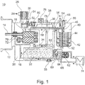
- Fig. 1 shows a schematic sectional view of a screw compressor 10 in the sense of an exemplary embodiment of the present invention.
- the screw compressor 10 has a fastening flange 12 for the mechanical fastening of the screw compressor 10 to an electric motor not shown in detail here.
- the screw 18 meshes with the screw 16 and is driven by this.
- the screw compressor 10 has a housing 20 in which the essential components of the screw compressor 10 are accommodated.
- the housing 20 is filled with oil 22.
- an inlet connector 24 is provided on the housing 20 of the screw compressor 10.
- the inlet connector 24 is designed such that an air filter 26 is arranged on it.
- an air inlet 28 is provided radially on the air inlet connector 24.
- a spring-loaded valve insert 30 is provided, designed here as an axial seal.
- This valve insert 30 serves as a check valve.
- An air supply channel 32 is provided downstream of the valve insert 30 and supplies the air to the two screws 16, 18.
- an air outlet pipe 34 with a riser 36 is provided on the output side of the two screws 16, 18.
- a temperature sensor 38 is provided, by means of which the oil temperature can be monitored.
- a holder 40 for an air / oil separator 42 is also provided in the air outlet area.
- the holder 40 for the exhaust filter has in the assembled state in the area facing the floor (as also in FIG Fig. 1 shown) the exhaust filter 42 on.
- a corresponding filter screen or known filter and oil separation devices 44 which are not specified in detail, are also provided inside the exhaust filter 42.
- the holder for the exhaust filter 40 has an air outlet opening 46, which lead to a check valve 48 and a minimum pressure valve 50.
- the check valve 48 and the minimum pressure valve 50 can also be formed in a common, combined valve.
- the air outlet 51 is provided downstream of the check valve 48.
- the air outlet 51 is usually connected to correspondingly known compressed air consumers.
- a riser 52 is provided which has a filter and check valve 54 at the outlet of the holder 40 for the exhaust filter 42 when it passes into the housing 20.
- a nozzle 56 is provided in a housing bore downstream of the filter and check valve 54.
- the oil return line 58 leads back approximately to the middle area of the screw 16 or the screw 18 in order to supply oil 22 again.
- An oil drain plug 59 is provided in the bottom area of the housing 20 in the assembled state. A corresponding oil drain opening through which the oil 22 can be drained can be opened via the oil drain screw 59.
- the housing 20 In the lower area of the housing 20 there is also the extension 60 to which the oil filter 62 is attached.
- the oil 22 is first fed to a thermostatic valve 66 via an oil filter inlet channel 64 which is arranged in the housing 20.
- thermostat valve 66 a control and / or regulating device can be provided, by means of which the oil temperature of the oil 22 located in the housing 20 can be monitored and adjusted to a setpoint value.
- a nozzle 72 is also provided, which is provided in the housing 20 in connection with the return line 68.
- the cooler 74 is connected to the extension 60.
- a safety valve 76 In the upper area of the housing 20 (in relation to the assembled state) there is a safety valve 76, via which an excessively high pressure in the housing 20 can be reduced.
- a bypass line 78 which leads to a relief valve 80, is located upstream of the minimum pressure valve 50. Air can be fed back into the area of the air inlet 28 via this relief valve 80, which is controlled by means of a connection to the air supply 32.
- a vent valve (not shown in more detail) and also a nozzle (diameter reduction of the supply line) can be provided in this area.
- an oil level sensor 82 can be provided approximately at the level of the line 34 in the outer wall of the housing 20.
- This oil level sensor 82 can, for example, be an optical sensor and can be designed and set up in such a way that the sensor signal can be used to identify whether the oil level is above the oil level sensor 82 during operation or whether the oil level sensor 82 is exposed and the oil level has fallen accordingly as a result.
- an alarm unit can also be provided that outputs or forwards a corresponding error message or warning message to the user of the system.
- the function of the in Fig. 1 shown screw compressor 10 is as follows: Air is supplied via the air inlet 28 and reaches the screws 16, 18 via the check valve 30, where the air is compressed. The compressed air-oil mixture, which rises with a factor of between 5 and 16 times compression after the screws 16 and 18 through the outlet line 34 via the riser pipe 36, is blown directly onto the temperature sensor 38.
- the air which still partially carries oil particles, is then guided via the holder 40 into the exhaust filter 42 and, if the corresponding minimum pressure is reached, reaches the air outlet line 51.
- the oil 22 located in the housing 20 is kept at operating temperature via the oil filter 62 and possibly via the heat exchanger 74.
- the heat exchanger 74 is not used and is also not switched on.
- the corresponding connection takes place via the thermostatic valve 68.
- oil is fed to the screw 18 or the screw 16, but also to the bearing 72, via the line 68.
- the screw 16 or the screw 18 is supplied with oil 22 via the return line 52, 58; here the oil 22 is purified in the exhaust filter 42.
- the screws 16 and 18 of the screw compressor 10 are driven by the electric motor, not shown in detail, which transmits its torque via the shaft 14 to the screw 16, which in turn meshes with the shaft 18.
- the relief valve 80 ensures that in the area of the supply line 32, the high pressure that prevails in the operating state, for example on the outlet side of the screws 16, 18, cannot be locked in, but that, especially when the compressor starts up, always in the area of the supply line 32 there is a low inlet pressure, in particular atmospheric pressure. Otherwise, when the compressor starts up, a very high pressure would initially arise on the output side of the screws 16 and 18, which would overload the drive motor.
- Fig. 2 shows the system 1 for a commercial vehicle in a perspective exposure view.
- the system 1 has an electric motor 5 and, as in FIG Fig. 1 screw compressor 10 shown.
- stator 90 of the electric motor 5 which has several windings 92 spaced apart from one another.
- the rotor of the electric motor 5 is not shown in detail.
- Drive electronics 94 are also provided.
- the electronic drive system 94 has a main board 96 and capacitive and inductive components 98 and a cooling element 100.
- a common housing component or housing 102 accommodates the rotor of the electric motor 5 on one side and the drive electronics 94 on the other side.
- the housing component 102 has an intermediate wall 104 which separates the drive electronics 94 from the rotor.
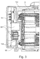
- This partition 104 has a recess directed in the direction of the windings 92 of the rotor, into which the capacitive and inductive elements 98, but also the cooling element 100 of the drive electronics 94 protrude.
Landscapes
- Engineering & Computer Science (AREA)
- Mechanical Engineering (AREA)
- General Engineering & Computer Science (AREA)
- Transportation (AREA)
- Applications Or Details Of Rotary Compressors (AREA)
- Compressor (AREA)
Description
- Die vorliegende Erfindung betrifft ein System für ein Nutzfahrzeug umfassend einen Schraubenkompressor sowie einen Elektromotor.
- Aus dem Stand der Technik sind bereits Schraubenkompressoren für Nutzfahrzeuge bekannt. Derartige Schraubenkompressoren werden verwendet, um die notwendige Druckluft für beispielsweise das Bremssystem des Nutzfahrzeugs bereitzustellen.
- In diesem Zusammenhang sind insbesondere Öl befüllte Kompressoren, insbesondere auch Schraubenkompressoren bekannt, bei denen sich als Aufgabe stellt, die Öltemperatur zu regulieren. Dies wird in der Regel dadurch bewerkstelligt, dass ein externer Ölkühler vorhanden ist, der mit dem Öl befüllten Kompressor und dem Ölkreislauf über ein Thermostatventil verbunden ist. Der Ölkühler ist dabei ein Wärmetauscher, der zwei voneinander getrennte Kreisläufe aufweist, wobei der erste Kreislauf für die heiße Flüssigkeit, also das Kompressoröl, vorgesehen ist und der zweite für die Kühlflüssigkeit. Als Kühlflüssigkeit können beispielsweise Luft, Wassergemische mit einem Frostschutzmittel oder einem anderen Öl verwendet werden.
- Dieser Ölkühler muss sodann mit dem Kompressorölkreislauf über Rohre oder Schläuche verbunden werden und der Ölkreislauf muss gegen Leckagen gesichert werden.
- Dieses externe Volumen muss des Weiteren mit Öl befüllt werden, so dass auch die Gesamtmenge an Öl vergrößert wird. Dadurch wird die Systemträgheit vergrößert. Darüber hinaus muss der Ölkühler mechanisch untergebracht und befestigt werden, entweder durch umliegend befindliche Halterungen oder durch eine gesonderte Halterung, was zusätzliche Befestigungsmittel, aber auch Bauraum benötigt.
- Aus der
US 4,780,061 ist bereits ein Schraubenkompressor mit einer integrierten Ölkühlung bekannt. - Des Weiteren offenbart die
DE 37 17 493 A1 eine in einem kompakten Gehäuse angeordnete Schraubenverdichter-Anlage, die einen Ölkühler auf dem Elektromotor des Schraubenkompressors aufweist. - Aus der
DE 10 2010 015 151 A1 ist ein Verdichterflansch für einen Schraubenverdichter bekannt. - Weiter ist aus der
US 2014/0190674 A1 ein Verbindungsflansch für einen Wärmetauscher eines Kraftfahrzeuges bekannt, der Kühlkanäle aufweist. - Aus der
DE 10 2013 011 061 B3 ist weiter ein Wärmetauscher mit einer Flanschverbindung bekannt, wobei die Flanschverbindung einen Anschlussflansch aufweist, der ein Druckgussteil ist und gießtechnisch hergestellte Durchgangslöcher zur Aufnahme von Schraubbolzen aufweist. - Aus der
WO 2009/033556 A1 ist ein trockenlaufender Kompressor bekannt, bei dem ein Elektromotor integriert ist. - Eine vergleichbare Anordnung ist auch aus der
CN 102748292 A bekannt. - Aus der
DE 10 2011 001 394 A1 ist ein elektrisch angetriebener Kältemittelverdichter bekannt, der einen Aussenläuferelektromotor mit Rotor und Stator, einen Verdichter und eine Antriebswelle für Elektromotor und Verdichter aufweist, wobei die Antriebswelle in einem Hauptgehäuse des Kältemittelverdichters mittels Wellenlagerung gelagert ist und das Hauptgehäuse dazu eine rohrförmige Ausstülpung in axialer Richtung aufweist, in deren Inneren die Antriebswelle konzentrisch und zweifach angeordnet ist. Ein Inverter ist im Gehäuse selbst gelagert. - Aus der
EP 1705379 A1 ist ein Schraubenkompressor bekannt, bei dem die Leistungselektronik ebenfalls im Gehäuse angeordnet ist. - Die
WO 2010/142631 A2 betrifft eine Vakuumpumpe, die von einem Elektromotor angetrieben wird. Zur Veränderung der Drehzahl des Elektromotors ist ein Frequenzumrichter vorgesehen, wobei der Frequenzumrichter unmittelbar mit dem Pumpengehäuse verbundenen Frequenzumrichtergehäuse angeordnet ist. Zur Kühlung des Frequenzumrichters ist innerhalb des Frequenzumrichtergehäuses ein Luftkühler sowie ein Flüssigkeitskühler angeordnet. - Es ist die Aufgabe der vorliegenden Erfindung, ein System für ein Nutzfahrzeug umfassend einen Kompressor, einen Elektromotor und eine Antriebselektronik der eingangs genannten Art in vorteilhafter Weise weiterzubilden, insbesondere dahingehend, dass der Platzbedarf eines derartigen Systems weiter verringert werden kann.
- Diese Aufgabe wird erfindungsgemäß gelöst durch ein System für ein Nutzfahrzeug mit den Merkmalen des Anspruchs 1. Danach ist vorgesehen, dass ein System für ein Nutzfahrzeug einen Kompressor, einen Elektromotor und eine Antriebselektronik umfasst, wobei Elektromotor und Antriebselektronik ein gemeinsames Gehäuse aufweisen und wobei der Elektromotor einen Rotor aufweist, der die Antriebswelle des Kompressors zumindest teilweise umgreift.
- Die Erfindung basiert auf dem Grundgedanken, für Elektromotor, Kompressor und Antriebselektronik eine gemeinsame bauliche Einheit herzustellen, so dass insgesamt eine kompakte bauliche Einheit für das System entstehen kann. Hierdurch wird es möglich, die axiale Länge insgesamt der gesamten Einheit zu verringern. Insbesondere dadurch, dass die Antriebselektronik mit in das Gehäuse des Elektromotors integriert wird, wird es möglich, kompakter bauen zu können.
- Der Kompressor kann ein Schraubenkompressor sein. Durch die Ausgestaltung als Schraubenkompressor wird ein effizienter und wirtschaftlicher Betrieb des Kompressors im Rahmen der Drucklufterzeugung für ein Nutzfahrzeug, insbesondere im Zusammenhang mit Hybrid-Nutzfahrzeugen, möglich. Bei derartigen Fahrzeugen verhält es sich insbesondere so, dass nicht kontinuierlich im Fahrbetrieb das Antriebsaggregat des Nutzfahrzeuges durchläuft und deshalb auch nicht jederzeit ein Antrieb des Kompressors durch das Antriebsaggregat möglich ist. Eine Abkopplung ist daher notwendig, weshalb der Einsatz von Schraubenkompressoren von Vorteil ist.
- Die Antriebselektronik kann auf der dem Kompressor abgewandten Seite des Elektromotors angeordnet sein. Hierdurch wird es möglich, die Komponenten des Systems im Wesentlichen entlang einer Achse anzuordnen und hierdurch den Bauraum auch optimal ausnutzen zu können.
- Der Elektromotor kann eine Antriebswelle aufweisen, mit der der Kompressor angetrieben wird und es kann vorgesehen sein, dass die Antriebselektronik radial zur Antriebswelle angeordnet ist. Durch eine derartige Anordnung wird es möglich, auch in radialer Richtung bezogen auf die Antriebswelle zur Verfügung stehenden Bauraum für Komponenten des Systems zu nutzen.
- Grundsätzlich ist es aber auch möglich, dass die Antriebselektronik axial zur Antriebswelle angeordnet ist. Je nach Ausgestaltung steht auch hier entsprechender Bauraum zur Verfügung, der ausgenutzt werden kann.
- Der Elektromotor kann einen Stator mit voneinander beabstandeten Windungen aufweisen, wobei die Antriebselektronik teilweise in Zwischenräume zwischen die Windungen hineinragt. Hierdurch wird es möglich, auch diese Zwischenräume als Bauraum für die Antriebselektronik zu nutzen. Eine kompakte Bauweise der gesamten Einheit wird hierdurch weiter verbessert und ermöglicht.
- Weitere Einzelheiten und Vorteile der Erfindung sollen nun anhand eines in den Zeichnungen dargestellten Ausführungsbeispiels näher erläutert werden.
-
- Fig. 1
- eine schematische Schnittdarstellung eines erfindungsgemäßen Ausführungsbeispiels für ein erfindungsgemäßes System für ein Nutzfahrzeug umfassend einen Schraubenkompressor sowie einen Elektromotor;
- Fig. 2
- eine perspektivische Exposionszeichnung auf die Komponenten eines erfindungsgemäßen Ausführungsbeispiels des Systems; und
- Fig. 3
- eine perspektivische Detailschnittzeichnung durch den Elektromotor und die Antriebselektronik des Elektromotors des Systems gemäß
Fig. 2 . -
Fig. 1 zeigt in einer schematischen Schnittdarstellung einen Schraubenkompressor 10 im Sinne eines Ausführungsbeispiels für die vorliegende Erfindung. - Der Schraubenkompressor 10 weist einen Befestigungsflansch 12 zur mechanischen Befestigung des Schraubenkompressors 10 an einem hier nicht näher gezeigten Elektromotor auf.
- Gezeigt ist jedoch die Eingangswelle 14, über die das Drehmoment vom Elektromotor auf eine der beiden Schrauben 16 und 18, nämlich die Schraube 16 übertragen wird.
- Die Schraube 18 kämmt mit der Schraube 16 und wird über diese angetrieben.
- Der Schraubenkompressor 10 weist ein Gehäuse 20 auf, in dem die wesentlichen Komponenten des Schraubenkompressors 10 untergebracht sind.
- Das Gehäuse 20 ist mit Öl 22 befüllt.
- Lufteingangsseitig ist am Gehäuse 20 des Schraubenkompressors 10 ein Einlassstutzen 24 vorgesehen. Der Einlassstutzen 24 ist dabei derart ausgebildet, dass an ihm ein Luftfilter 26 angeordnet ist. Außerdem ist radial am Lufteinlassstutzen 24 ein Lufteinlass 28 vorgesehen.
- Im Bereich zwischen Einlassstutzen 24 und der Stelle, an dem der Einlassstutzen 24 am Gehäuse 20 ansetzt, ist ein federbelasteter Ventileinsatz 30 vorgesehen, hier als Axialdichtung ausgeführt.
- Dieser Ventileinsatz 30 dient als Rückschlagventil.
- Stromabwärts des Ventileinsatzes 30 ist ein Luftzuführkanal 32 vorgesehen, der die Luft den beiden Schrauben 16, 18 zuführt.
- Ausgangsseitig der beiden Schrauben 16, 18 ist ein Luftauslassrohr 34 mit einer Steigleitung 36 vorgesehen.
- Im Bereich des Endes der Steigleitung 36 ist ein Temperaturfühler 38 vorgesehen, mittels dessen die Öltemperatur überwachbar ist.
- Weiter vorgesehen ist im Luftauslassbereich ein Halter 40 für ein Luftentölelement 42.
- Der Halter 40 für das Luftentölelement weist im montierten Zustand im dem Boden zugewandten Bereich (wie auch in
Fig. 1 gezeigt) das Luftentölelement 42 auf. - Weiter vorgesehen ist im Inneren der Luftentölelement 42 ein entsprechendes Filtersieb bzw. bekannte Filter- und Ölabscheidevorrichtungen 44, die nicht näher im Einzelnen spezifiziert werden.
- Im zentralen oberen Bereich, bezogen auf den montierten und betriebsfertigen Zustand (also wie in
Fig. 1 gezeigt), weist der Halter für das Luftentölelement 40 eine Luftausgangsöffnung 46 auf, die zu einem Rückschlagventil 48 und einem Mindestdruckventil 50 führen. Das Rückschlagventil 48 und das Mindestdruckventil 50 können auch in einem gemeinsamen, kombinierten Ventil ausgebildet sein. - Nachfolgend des Rückschlagventils 48 ist der Luftauslass 51 vorgesehen.
- Der Luftauslass 51 ist mit entsprechend bekannten Druckluftverbrauchern in der Regel verbunden.
- Um das im Luftentölelement 42 befindliche und abgeschiedene Öl 22 wieder in das Gehäuse 20 zurückzuführen, ist eine Steigleitung 52 vorgesehen, die ausgangs des Halters 40 für das Luftentölelement 42 beim Übertritt in das Gehäuse 20 ein Filter- und Rückschlagventil 54 aufweist.
- Stromabwärts des Filter- und Rückschlagventils 54 ist in einer Gehäusebohrung eine Düse 56 vorgesehen. Die Ölrückführleitung 58 führt zurück in etwa den mittleren Bereich der Schraube 16 oder der Schraube 18, um dieser wieder Öl 22 zuzuführen.
- Im im montierten Zustand befindlichen Bodenbereich des Gehäuses 20 ist eine Ölablassschraube 59 vorgesehen. Über die Ölablassschraube 59 kann eine entsprechende Ölablauföffnung geöffnet werden, über die das Öl 22 abgelassen werden kann.
- Im unteren Bereich des Gehäuses 20 ist auch der Ansatz 60 vorhanden, an dem der Ölfilter 62 befestigt wird. Über einen Ölfiltereinlasskanal 64, der im Gehäuse 20 angeordnet ist, wird das Öl 22 zunächst zu einem Thermostatventil 66 geleitet.
- Anstelle des Thermostatventils 66 kann eine Steuerungs- und/oder Regelungseinrichtung vorgesehen sein, mittels derer die Öltemperatur des im Gehäuse 20 befindlichen Öls 22 überwachbar und auf einen Sollwert einstellbar ist.
- Stromabwärts des Thermostatventils 66 ist sodann der Öleinlass des Ölfilters 62, der über eine zentrale Rückführleitung 68 das Öl 22 wieder zurück zur Schraube 18 oder zur Schraube 16, aber auch zum ölgeschmierten Lager 70 der Welle 14 führt. Im Bereich des Lagers 70 ist auch eine Düse 72 vorgesehen, die im Gehäuse 20 im Zusammenhang mit der Rückführleitung 68 vorgesehen ist.
- Der Kühler 74 ist am Ansatz 60 angeschlossen.
- Im oberen Bereich des Gehäuses 20 (bezogen auf den montierten Zustand) befindet sich ein Sicherheitsventil 76, über das ein zu großer Druck im Gehäuse 20 abgebaut werden kann.
- Vor dem Mindestdruckventil 50 befindet sich eine Bypassleitung 78, die zu einem Entlastungsventil 80 führt. Über dieses Entlastungsventil 80 das mittels einer Verbindung mit der Luftzuführung 32 angesteuert wird kann Luft in den Bereich des Lufteinlasses 28 zurückgeführt werden. In diesem Bereich kann ein nicht näher gezeigtes Entlüftungsventil und auch eine Düse (Durchmesserveringerung der zuführenden Leitung) vorgesehen sein.
- Darüber hinaus kann ungefähr auf Höhe der Leitung 34 in der Außenwand des Gehäuses 20 ein Öllevelsensor 82 vorgesehen sein. Dieser Öllevelsensor 82 kann beispielsweise ein optischer Sensor sein und derart beschaffen und eingerichtet, dass anhand des Sensorsignals erkannt werden kann, ob der Ölstand im Betrieb oberhalb des Öllevelsensors 82 ist oder ob der Öllevelsensor 82 frei liegt und hierdurch der Ölstand entsprechend gefallen ist.
- Im Zusammenhang mit dieser Überwachung kann auch eine Alarmeinheit vorgesehen sein, die eine entsprechende Fehlermeldung oder Warnmeldung an den Nutzer des Systems ausgibt bzw. weiterleitet.
- Die Funktion des in
Fig. 1 gezeigten Schraubenkompressors 10 ist dabei wie folgt:
Luft wird über den Lufteinlass 28 zugeführt und gelangt über das Rückschlagventil 30 zu den Schrauben 16, 18, wo die Luft komprimiert wird. Das komprimierte Luft-Öl-Gemisch, das mit einem Faktor zwischen 5- bis 16facher Komprimierung nach den Schrauben 16 und 18 durch die Auslassleitung 34 über das Steigrohr 36 aufsteigt, wird direkt auf den Temperaturfühler 38 geblasen. - Die Luft, die noch teilweise Ölpartikel trägt, wird sodann über den Halter 40 in das Luftentölelement 42 geführt und gelangt, sofern der entsprechende Mindestdruck erreicht wird, in die Luftauslassleitung 51.
- Das im Gehäuse 20 befindliche Öl 22 wird über den Ölfilter 62 und ggf. über den Wärmetauscher 74 auf Betriebstemperatur gehalten.
- Sofern keine Kühlung notwendig ist, wird der Wärmetauscher 74 nicht verwendet und ist auch nicht zugeschaltet.
- Die entsprechende Zuschaltung erfolgt über das Thermostatventil 68. Nach der Aufreinigung im Ölfilter 64 wird über die Leitung 68 Öl der Schraube 18 oder der Schraube 16, aber auch dem Lager 72 zugeführt. Die Schraube 16 oder die Schraube 18 wird über die Rückführleitung 52, 58 mit Öl 22 versorgt, hier erfolgt die Aufreinigung des Öls 22 im Luftentölelement 42.
- Über den nicht näher gezeigten Elektromotor, der sein Drehmoment über die Welle 14 auf die Schraube 16 überträgt, die wiederum mit der Welle 18 kämmt, werden die Schrauben 16 und 18 des Schraubenkompressors 10 angetrieben.
- Über das nicht näher gezeigte Entlastungsventil 80 wird sichergestellt, dass im Bereich der Zuleitung 32 nicht der hohe Druck, der im Betriebszustand beispielsweise ausgangsseitig der Schrauben 16, 18 herrscht, eingesperrt werden kann, sondern dass insbesondere beim Anlaufen des Kompressors im Bereich der Zuleitung 32 stets ein niedriger Eingangsdruck, insbesondere Atmosphärendruck, besteht. Andernfalls würde mit einem Anlaufen des Kompressors zunächst ein sehr hoher Druck ausgangsseitig der Schrauben 16 und 18 entstehen, der den Antriebsmotor überlasten würde.
-
Fig. 2 zeigt in perspektivischer Exposionsdarstellung das Systems 1 für ein Nutzfahrzeug. - Das System 1 weist einen Elektromotor 5 und einen, wie in
Fig. 1 gezeigten Schraubenkompressor 10 auf. - Weitere Komponenten des Systems 1 sind der Stator 90 des Elektromotors 5, der mehrere voneinander beabstandete Windungen 92 aufweist. Der Rotor des Elektromotors 5 ist nicht näher dargestellt.
- Darüber hinaus ist eine Antriebselektronik 94 vorgesehen.
- Dabei weist die Antriebselektronik 94 eine Hauptplatine 96 und kapazitive und induktive Komponenten 98 und ein Kühlelement 100 auf.
- Wie bereits aus
Fig. 2 ersichtlich ist, werden durch ein gemeinsames Gehäusebauteil bzw. Gehäuse 102 auf der einen Seite der Rotor des Elektromotors 5 und auf der anderen Seite die Antriebselektronik 94 aufgenommen. - Das Gehäusebauteil 102 weist eine Zwischenwand 104 auf, die die Antriebselektronik 94 vom Rotor trennt.
- Dies ist insbesondere gut in der Detaildarstellung in
Fig. 3 ersichtlich. - Diese Zwischenwand 104 weist eine in Richtung der Windungen 92 des Rotors gerichtete Ausnehmung auf, in die die kapazitiven und induktiven Elemente 98, aber auch das Kühlelement 100 der Antriebselektronik 94 hineinragen.
- Hierdurch kann die axiale Baulänge des Gesamtsystems 1 verringert werden.
-
- 1
- System
- 5
- Elektromotor
- 10
- Schraubenkompressor
- 12
- Befestigungsflansch
- 14
- Eingangswelle
- 16
- Schrauben
- 18
- Schrauben
- 20
- Gehäuse
- 22
- Öl
- 24
- Einlassstutzen
- 26
- Luftfilter
- 28
- Lufteinlass
- 30
- Ventileinsatz
- 32
- Luftzuführkanal
- 34
- Luftauslassrohr
- 36
- Steigleitung
- 38
- Temperaturfühler
- 40
- Luftölabscheider
- 42
- Ölfalle
- 44
- Filtersieb bzw. bekannte Filter- bzw. Ölabscheidevorrichtungen
- 46
- Luftausgangsöffnung
- 48
- Kontrollventil
- 50
- Mindestdruckventil
- 51
- Luftauslass
- 52
- Steigleitung
- 54
- Filter- und Kontrollventil
- 56
- Choke
- 58
- Ölrückführleitung
- 59
- Ölablassschraube
- 60
- Ansatz
- 62
- Ölfilter
- 64
- Ölfiltereinlasskanal
- 66
- Thermostatventil
- 68
- Rückführleitung
- 70
- Lager
- 72
- Choke
- 76
- Sicherheitsventil
- 78
- Bypassleitung
- 80
- Entlastungsventil
- 82
- Öllevelsensor
- 90
- Stator
- 92
- Windungen
- 94
- Antriebselektronik
- 96
- Hauptplatine
- 98
- kapazitive und induktive Komponente
- 100
- Kühlelement
- 102
- Gehäusebauteil
- 104
- Zwischenwand
Claims (5)
- System (1) für ein Nutzfahrzeug umfassend einen Kompressor (10), einen Elektromotor (5) und eine Antriebselektronik (94), wobei der Elektromotor (5) den Kompressor (10) antreibt, wobei Elektromotor (5) und Antriebselektronik (94) ein gemeinsames Gehäuse (102) aufweisen und wobei der Elektromotor (5) einen Rotor aufweist, der die Antriebswelle des Kompressors (10) zumindest teilweise wobei der Elektromotor (5) einen Stator (90) mit voneinander beabstandeten Windungen (92) aufweist, wobei die Antriebselektronik (94) teilweise in Zwischenräume zwischen Windungen (92) hineinragt, wobei die Antriebselektronik (94) eine Hauptplatine (96) und kapazitive und induktive Komponenten (98) und ein Kühlelement (100) aufweist und
wobei das Gehäuse (102) eine Zwischenwand (104) aufweist, die die Antriebselektronik (94) vom Rotor trennt und wobei die Zwischenwand (104) in eine Richtung der Windungen (92) des Rotors gerichtete Ausnehmung aufweist, in die die kapazitive und induktiven Komponenten (98), aber auch das Kühlelement der Antriebselektronik (94) hineinragen.. - System (1) nach Anspruch 1,
dadurch gekennzeichnet, dass
der Kompressor (10) ein Schraubenkompressor (10) ist. - System (1) nach Anspruch 1 oder Anspruch 2,
dadurch gekennzeichnet, dass
die Antriebselektronik (94) auf der dem Kompressor (10) abgewandten Seite des Elektromotors (5) angeordnet ist. - System (1) nach einem der vorhergehenden Ansprüche,
dadurch gekennzeichnet, dass
der Elektromotor (5) eine Antriebswelle aufweist, mit der der Kompressor (10) angetrieben wird, und dass die Antriebselektronik (94) radial zur Antriebswelle angeordnet ist. - System (1) nach Anspruch 3,
dadurch gekennzeichnet, dass
der Elektromotor (5) eine Antriebswelle aufweist, mit der der Kompressor (10) angetrieben wird, und dass die Antriebselektronik (94) axial zur Antriebswelle angeordnet ist.
Applications Claiming Priority (2)
| Application Number | Priority Date | Filing Date | Title |
|---|---|---|---|
| DE102016011504.1A DE102016011504A1 (de) | 2016-09-21 | 2016-09-21 | System für ein Nutzfahrzeug umfassend einen Schraubenkompressor sowie einen Elektromotor |
| PCT/EP2017/073552 WO2018054867A1 (de) | 2016-09-21 | 2017-09-19 | System für ein nutzfahrzeug umfassend einen kompressor sowie einen elektromotor |
Publications (2)
| Publication Number | Publication Date |
|---|---|
| EP3516236A1 EP3516236A1 (de) | 2019-07-31 |
| EP3516236B1 true EP3516236B1 (de) | 2020-08-19 |
Family
ID=60037547
Family Applications (1)
| Application Number | Title | Priority Date | Filing Date |
|---|---|---|---|
| EP17780637.9A Active EP3516236B1 (de) | 2016-09-21 | 2017-09-19 | System für ein nutzfahrzeug umfassend einen kompressor sowie einen elektromotor |
Country Status (8)
| Country | Link |
|---|---|
| US (1) | US20190249665A1 (de) |
| EP (1) | EP3516236B1 (de) |
| JP (1) | JP6775689B2 (de) |
| KR (1) | KR20190045376A (de) |
| CN (1) | CN109906318B (de) |
| BR (1) | BR112019005096A2 (de) |
| DE (1) | DE102016011504A1 (de) |
| WO (1) | WO2018054867A1 (de) |
Families Citing this family (2)
| Publication number | Priority date | Publication date | Assignee | Title |
|---|---|---|---|---|
| US11767837B2 (en) * | 2019-11-14 | 2023-09-26 | Vanair Manufacturing, Inc. | Compressor control systems and air compressor systems and vehicles equipped therewith |
| DE102023209588A1 (de) * | 2023-09-29 | 2025-04-03 | Brose Fahrzeugteile SE & Co. Kommanditgesellschaft, Würzburg | Verdichter für ein Kraftfahrzeug |
Family Cites Families (16)
| Publication number | Priority date | Publication date | Assignee | Title |
|---|---|---|---|---|
| US4748873A (en) | 1986-05-23 | 1988-06-07 | Raymond Engineering Inc. | Power wrench |
| US4780061A (en) | 1987-08-06 | 1988-10-25 | American Standard Inc. | Screw compressor with integral oil cooling |
| US5246349A (en) * | 1991-03-18 | 1993-09-21 | Sullair Corporation | Variable reluctance electric motor driven vacuum pump |
| DE19749572A1 (de) * | 1997-11-10 | 1999-05-12 | Peter Dipl Ing Frieden | Trockenlaufender Schraubenverdichter oder Vakuumpumpe |
| US6257840B1 (en) * | 1999-11-08 | 2001-07-10 | Copeland Corporation | Scroll compressor for natural gas |
| US6652250B2 (en) * | 2000-10-16 | 2003-11-25 | Kobe Steel, Ltd. | Screw compressor having intermediate shaft bearing |
| WO2005061900A1 (ja) * | 2003-12-22 | 2005-07-07 | Mitsubishi Denki Kabushiki Kaisha | スクリュー圧縮機 |
| DE102007042318B4 (de) | 2007-09-06 | 2017-11-30 | Knorr-Bremse Systeme für Nutzfahrzeuge GmbH | Kompakter trockenlaufender Kolbenverdichter |
| DE102009024336A1 (de) * | 2009-06-09 | 2010-12-23 | Oerlikon Leybold Vacuum Gmbh | Vakuumpumpe |
| DE102010015151A1 (de) | 2010-04-16 | 2011-10-20 | Knorr-Bremse Systeme für Schienenfahrzeuge GmbH | Verdichterflansch für Schraubenverdichter |
| JP2012188970A (ja) * | 2011-03-09 | 2012-10-04 | Nissin Kogyo Co Ltd | ベーンポンプ |
| DE102011001394B4 (de) * | 2011-03-18 | 2015-04-16 | Halla Visteon Climate Control Corporation 95 | Elektrisch angetriebener Kältemittelverdichter |
| FR2978237B1 (fr) | 2011-07-21 | 2013-12-20 | Valeo Systemes Thermiques | Bride de connexion, boite collectrice et echangeur thermique associes |
| CN102748292B (zh) | 2012-07-18 | 2015-07-01 | 无锡五洋赛德压缩机有限公司 | 恒压变量智能空压机 |
| DE102013208538A1 (de) * | 2013-05-08 | 2014-11-13 | Lenze Drives Gmbh | Antriebssystem |
| DE102013011061B3 (de) | 2013-07-02 | 2014-10-09 | Modine Manufacturing Company | Wärmetauscher mit einer Flanschverbindung |
-
2016
- 2016-09-21 DE DE102016011504.1A patent/DE102016011504A1/de not_active Withdrawn
-
2017
- 2017-09-19 EP EP17780637.9A patent/EP3516236B1/de active Active
- 2017-09-19 KR KR1020197011045A patent/KR20190045376A/ko not_active Ceased
- 2017-09-19 WO PCT/EP2017/073552 patent/WO2018054867A1/de not_active Ceased
- 2017-09-19 BR BR112019005096A patent/BR112019005096A2/pt not_active Application Discontinuation
- 2017-09-19 JP JP2019536674A patent/JP6775689B2/ja not_active Expired - Fee Related
- 2017-09-19 CN CN201780068597.5A patent/CN109906318B/zh not_active Expired - Fee Related
- 2017-09-19 US US16/331,089 patent/US20190249665A1/en not_active Abandoned
Non-Patent Citations (1)
| Title |
|---|
| None * |
Also Published As
| Publication number | Publication date |
|---|---|
| DE102016011504A1 (de) | 2018-03-22 |
| EP3516236A1 (de) | 2019-07-31 |
| BR112019005096A2 (pt) | 2019-06-04 |
| CN109906318B (zh) | 2020-10-16 |
| WO2018054867A1 (de) | 2018-03-29 |
| JP2019529802A (ja) | 2019-10-17 |
| KR20190045376A (ko) | 2019-05-02 |
| CN109906318A (zh) | 2019-06-18 |
| JP6775689B2 (ja) | 2020-10-28 |
| US20190249665A1 (en) | 2019-08-15 |
Similar Documents
| Publication | Publication Date | Title |
|---|---|---|
| EP3516171B1 (de) | Schraubenkompressor für ein nutzfahrzeug | |
| EP3516221B1 (de) | Schraubenkompressorsystem für ein nutzfahrzeug | |
| EP3516237A1 (de) | System für ein nutzfahrzeug umfassend einen schraubenkompressor sowie einen elektromotor mit gemeinsamer kühlung | |
| EP3516230A1 (de) | Schraubenkompressorsystem für ein nutzfahrzeug | |
| EP3516227A1 (de) | System für ein nutzfahrzeug umfassend einen schraubenkompressor sowie einen elektromotor | |
| EP3516234B1 (de) | Schraubenkompressor für ein nutzfahrzeug | |
| EP3516236A1 (de) | System für ein nutzfahrzeug umfassend einen kompressor sowie einen elektromotor | |
| EP3596340B1 (de) | Kompressorsystem mit regelbarer und/oder steuerbarer temperaturüberwachungseinrichtung | |
| WO2018054883A1 (de) | Schraubenkompressor für ein nutzfahrzeug | |
| EP3516224B1 (de) | Schraubenkompressor für ein nutzfahrzeug | |
| EP3516222A1 (de) | Schraubenkompressor für ein nutzfahrzeug | |
| WO2018054859A1 (de) | Schraubenkompressor für ein nutzfahrzeug | |
| EP3516220A1 (de) | Anordnung für einen schraubenkompressor eines nutzfahrzeugs | |
| WO2018054879A1 (de) | Schraubenkompressorsystem für ein nutzfahrzeug | |
| EP3516226B1 (de) | Schraubenkompressor für ein nutzfahrzeug | |
| EP3516231B1 (de) | Schraubenkompressor für ein nutzfahrzeug | |
| EP3516235A1 (de) | Schraubenkompressor für ein nutzfahrzeug | |
| EP3516229A1 (de) | Schraubenkompressorsystem für ein nutzfahrzeug |
Legal Events
| Date | Code | Title | Description |
|---|---|---|---|
| STAA | Information on the status of an ep patent application or granted ep patent |
Free format text: STATUS: UNKNOWN |
|
| STAA | Information on the status of an ep patent application or granted ep patent |
Free format text: STATUS: THE INTERNATIONAL PUBLICATION HAS BEEN MADE |
|
| PUAI | Public reference made under article 153(3) epc to a published international application that has entered the european phase |
Free format text: ORIGINAL CODE: 0009012 |
|
| STAA | Information on the status of an ep patent application or granted ep patent |
Free format text: STATUS: REQUEST FOR EXAMINATION WAS MADE |
|
| 17P | Request for examination filed |
Effective date: 20190423 |
|
| AK | Designated contracting states |
Kind code of ref document: A1 Designated state(s): AL AT BE BG CH CY CZ DE DK EE ES FI FR GB GR HR HU IE IS IT LI LT LU LV MC MK MT NL NO PL PT RO RS SE SI SK SM TR |
|
| AX | Request for extension of the european patent |
Extension state: BA ME |
|
| DAV | Request for validation of the european patent (deleted) | ||
| DAX | Request for extension of the european patent (deleted) | ||
| GRAP | Despatch of communication of intention to grant a patent |
Free format text: ORIGINAL CODE: EPIDOSNIGR1 |
|
| STAA | Information on the status of an ep patent application or granted ep patent |
Free format text: STATUS: GRANT OF PATENT IS INTENDED |
|
| INTG | Intention to grant announced |
Effective date: 20200317 |
|
| GRAS | Grant fee paid |
Free format text: ORIGINAL CODE: EPIDOSNIGR3 |
|
| GRAA | (expected) grant |
Free format text: ORIGINAL CODE: 0009210 |
|
| STAA | Information on the status of an ep patent application or granted ep patent |
Free format text: STATUS: THE PATENT HAS BEEN GRANTED |
|
| AK | Designated contracting states |
Kind code of ref document: B1 Designated state(s): AL AT BE BG CH CY CZ DE DK EE ES FI FR GB GR HR HU IE IS IT LI LT LU LV MC MK MT NL NO PL PT RO RS SE SI SK SM TR |
|
| REG | Reference to a national code |
Ref country code: CH Ref legal event code: EP |
|
| REG | Reference to a national code |
Ref country code: DE Ref legal event code: R096 Ref document number: 502017006853 Country of ref document: DE |
|
| REG | Reference to a national code |
Ref country code: AT Ref legal event code: REF Ref document number: 1304227 Country of ref document: AT Kind code of ref document: T Effective date: 20200915 |
|
| REG | Reference to a national code |
Ref country code: IE Ref legal event code: FG4D Free format text: LANGUAGE OF EP DOCUMENT: GERMAN |
|
| REG | Reference to a national code |
Ref country code: LT Ref legal event code: MG4D |
|
| REG | Reference to a national code |
Ref country code: NL Ref legal event code: MP Effective date: 20200819 |
|
| PG25 | Lapsed in a contracting state [announced via postgrant information from national office to epo] |
Ref country code: FI Free format text: LAPSE BECAUSE OF FAILURE TO SUBMIT A TRANSLATION OF THE DESCRIPTION OR TO PAY THE FEE WITHIN THE PRESCRIBED TIME-LIMIT Effective date: 20200819 Ref country code: GR Free format text: LAPSE BECAUSE OF FAILURE TO SUBMIT A TRANSLATION OF THE DESCRIPTION OR TO PAY THE FEE WITHIN THE PRESCRIBED TIME-LIMIT Effective date: 20201120 Ref country code: LT Free format text: LAPSE BECAUSE OF FAILURE TO SUBMIT A TRANSLATION OF THE DESCRIPTION OR TO PAY THE FEE WITHIN THE PRESCRIBED TIME-LIMIT Effective date: 20200819 Ref country code: HR Free format text: LAPSE BECAUSE OF FAILURE TO SUBMIT A TRANSLATION OF THE DESCRIPTION OR TO PAY THE FEE WITHIN THE PRESCRIBED TIME-LIMIT Effective date: 20200819 Ref country code: BG Free format text: LAPSE BECAUSE OF FAILURE TO SUBMIT A TRANSLATION OF THE DESCRIPTION OR TO PAY THE FEE WITHIN THE PRESCRIBED TIME-LIMIT Effective date: 20201119 Ref country code: SE Free format text: LAPSE BECAUSE OF FAILURE TO SUBMIT A TRANSLATION OF THE DESCRIPTION OR TO PAY THE FEE WITHIN THE PRESCRIBED TIME-LIMIT Effective date: 20200819 Ref country code: NO Free format text: LAPSE BECAUSE OF FAILURE TO SUBMIT A TRANSLATION OF THE DESCRIPTION OR TO PAY THE FEE WITHIN THE PRESCRIBED TIME-LIMIT Effective date: 20201119 Ref country code: PT Free format text: LAPSE BECAUSE OF FAILURE TO SUBMIT A TRANSLATION OF THE DESCRIPTION OR TO PAY THE FEE WITHIN THE PRESCRIBED TIME-LIMIT Effective date: 20201221 |
|
| PGFP | Annual fee paid to national office [announced via postgrant information from national office to epo] |
Ref country code: DE Payment date: 20201125 Year of fee payment: 4 |
|
| PG25 | Lapsed in a contracting state [announced via postgrant information from national office to epo] |
Ref country code: PL Free format text: LAPSE BECAUSE OF FAILURE TO SUBMIT A TRANSLATION OF THE DESCRIPTION OR TO PAY THE FEE WITHIN THE PRESCRIBED TIME-LIMIT Effective date: 20200819 Ref country code: RS Free format text: LAPSE BECAUSE OF FAILURE TO SUBMIT A TRANSLATION OF THE DESCRIPTION OR TO PAY THE FEE WITHIN THE PRESCRIBED TIME-LIMIT Effective date: 20200819 Ref country code: NL Free format text: LAPSE BECAUSE OF FAILURE TO SUBMIT A TRANSLATION OF THE DESCRIPTION OR TO PAY THE FEE WITHIN THE PRESCRIBED TIME-LIMIT Effective date: 20200819 Ref country code: LV Free format text: LAPSE BECAUSE OF FAILURE TO SUBMIT A TRANSLATION OF THE DESCRIPTION OR TO PAY THE FEE WITHIN THE PRESCRIBED TIME-LIMIT Effective date: 20200819 Ref country code: IS Free format text: LAPSE BECAUSE OF FAILURE TO SUBMIT A TRANSLATION OF THE DESCRIPTION OR TO PAY THE FEE WITHIN THE PRESCRIBED TIME-LIMIT Effective date: 20201219 |
|
| PG25 | Lapsed in a contracting state [announced via postgrant information from national office to epo] |
Ref country code: EE Free format text: LAPSE BECAUSE OF FAILURE TO SUBMIT A TRANSLATION OF THE DESCRIPTION OR TO PAY THE FEE WITHIN THE PRESCRIBED TIME-LIMIT Effective date: 20200819 Ref country code: RO Free format text: LAPSE BECAUSE OF FAILURE TO SUBMIT A TRANSLATION OF THE DESCRIPTION OR TO PAY THE FEE WITHIN THE PRESCRIBED TIME-LIMIT Effective date: 20200819 Ref country code: CZ Free format text: LAPSE BECAUSE OF FAILURE TO SUBMIT A TRANSLATION OF THE DESCRIPTION OR TO PAY THE FEE WITHIN THE PRESCRIBED TIME-LIMIT Effective date: 20200819 Ref country code: DK Free format text: LAPSE BECAUSE OF FAILURE TO SUBMIT A TRANSLATION OF THE DESCRIPTION OR TO PAY THE FEE WITHIN THE PRESCRIBED TIME-LIMIT Effective date: 20200819 Ref country code: SM Free format text: LAPSE BECAUSE OF FAILURE TO SUBMIT A TRANSLATION OF THE DESCRIPTION OR TO PAY THE FEE WITHIN THE PRESCRIBED TIME-LIMIT Effective date: 20200819 |
|
| REG | Reference to a national code |
Ref country code: CH Ref legal event code: PL |
|
| REG | Reference to a national code |
Ref country code: DE Ref legal event code: R097 Ref document number: 502017006853 Country of ref document: DE |
|
| PG25 | Lapsed in a contracting state [announced via postgrant information from national office to epo] |
Ref country code: ES Free format text: LAPSE BECAUSE OF FAILURE TO SUBMIT A TRANSLATION OF THE DESCRIPTION OR TO PAY THE FEE WITHIN THE PRESCRIBED TIME-LIMIT Effective date: 20200819 Ref country code: AL Free format text: LAPSE BECAUSE OF FAILURE TO SUBMIT A TRANSLATION OF THE DESCRIPTION OR TO PAY THE FEE WITHIN THE PRESCRIBED TIME-LIMIT Effective date: 20200819 Ref country code: MC Free format text: LAPSE BECAUSE OF FAILURE TO SUBMIT A TRANSLATION OF THE DESCRIPTION OR TO PAY THE FEE WITHIN THE PRESCRIBED TIME-LIMIT Effective date: 20200819 |
|
| REG | Reference to a national code |
Ref country code: BE Ref legal event code: MM Effective date: 20200930 |
|
| PLBE | No opposition filed within time limit |
Free format text: ORIGINAL CODE: 0009261 |
|
| STAA | Information on the status of an ep patent application or granted ep patent |
Free format text: STATUS: NO OPPOSITION FILED WITHIN TIME LIMIT |
|
| PG25 | Lapsed in a contracting state [announced via postgrant information from national office to epo] |
Ref country code: LU Free format text: LAPSE BECAUSE OF NON-PAYMENT OF DUE FEES Effective date: 20200919 Ref country code: SK Free format text: LAPSE BECAUSE OF FAILURE TO SUBMIT A TRANSLATION OF THE DESCRIPTION OR TO PAY THE FEE WITHIN THE PRESCRIBED TIME-LIMIT Effective date: 20200819 |
|
| 26N | No opposition filed |
Effective date: 20210520 |
|
| PG25 | Lapsed in a contracting state [announced via postgrant information from national office to epo] |
Ref country code: FR Free format text: LAPSE BECAUSE OF NON-PAYMENT OF DUE FEES Effective date: 20201019 Ref country code: IT Free format text: LAPSE BECAUSE OF FAILURE TO SUBMIT A TRANSLATION OF THE DESCRIPTION OR TO PAY THE FEE WITHIN THE PRESCRIBED TIME-LIMIT Effective date: 20200819 |
|
| PG25 | Lapsed in a contracting state [announced via postgrant information from national office to epo] |
Ref country code: IE Free format text: LAPSE BECAUSE OF NON-PAYMENT OF DUE FEES Effective date: 20200919 Ref country code: LI Free format text: LAPSE BECAUSE OF NON-PAYMENT OF DUE FEES Effective date: 20200930 Ref country code: SI Free format text: LAPSE BECAUSE OF FAILURE TO SUBMIT A TRANSLATION OF THE DESCRIPTION OR TO PAY THE FEE WITHIN THE PRESCRIBED TIME-LIMIT Effective date: 20200819 Ref country code: BE Free format text: LAPSE BECAUSE OF NON-PAYMENT OF DUE FEES Effective date: 20200930 Ref country code: CH Free format text: LAPSE BECAUSE OF NON-PAYMENT OF DUE FEES Effective date: 20200930 |
|
| REG | Reference to a national code |
Ref country code: DE Ref legal event code: R119 Ref document number: 502017006853 Country of ref document: DE |
|
| GBPC | Gb: european patent ceased through non-payment of renewal fee |
Effective date: 20210919 |
|
| PG25 | Lapsed in a contracting state [announced via postgrant information from national office to epo] |
Ref country code: TR Free format text: LAPSE BECAUSE OF FAILURE TO SUBMIT A TRANSLATION OF THE DESCRIPTION OR TO PAY THE FEE WITHIN THE PRESCRIBED TIME-LIMIT Effective date: 20200819 Ref country code: MT Free format text: LAPSE BECAUSE OF FAILURE TO SUBMIT A TRANSLATION OF THE DESCRIPTION OR TO PAY THE FEE WITHIN THE PRESCRIBED TIME-LIMIT Effective date: 20200819 Ref country code: CY Free format text: LAPSE BECAUSE OF FAILURE TO SUBMIT A TRANSLATION OF THE DESCRIPTION OR TO PAY THE FEE WITHIN THE PRESCRIBED TIME-LIMIT Effective date: 20200819 |
|
| PG25 | Lapsed in a contracting state [announced via postgrant information from national office to epo] |
Ref country code: MK Free format text: LAPSE BECAUSE OF FAILURE TO SUBMIT A TRANSLATION OF THE DESCRIPTION OR TO PAY THE FEE WITHIN THE PRESCRIBED TIME-LIMIT Effective date: 20200819 |
|
| PG25 | Lapsed in a contracting state [announced via postgrant information from national office to epo] |
Ref country code: GB Free format text: LAPSE BECAUSE OF NON-PAYMENT OF DUE FEES Effective date: 20210919 Ref country code: DE Free format text: LAPSE BECAUSE OF NON-PAYMENT OF DUE FEES Effective date: 20220401 |
|
| REG | Reference to a national code |
Ref country code: AT Ref legal event code: MM01 Ref document number: 1304227 Country of ref document: AT Kind code of ref document: T Effective date: 20220919 |
|
| PG25 | Lapsed in a contracting state [announced via postgrant information from national office to epo] |
Ref country code: AT Free format text: LAPSE BECAUSE OF NON-PAYMENT OF DUE FEES Effective date: 20220919 |