EP3515844B1 - Verpackungsanordnung - Google Patents
Verpackungsanordnung Download PDFInfo
- Publication number
- EP3515844B1 EP3515844B1 EP17847801.2A EP17847801A EP3515844B1 EP 3515844 B1 EP3515844 B1 EP 3515844B1 EP 17847801 A EP17847801 A EP 17847801A EP 3515844 B1 EP3515844 B1 EP 3515844B1
- Authority
- EP
- European Patent Office
- Prior art keywords
- cleat
- assembly
- cleats
- side support
- sockets
- Prior art date
- Legal status (The legal status is an assumption and is not a legal conclusion. Google has not performed a legal analysis and makes no representation as to the accuracy of the status listed.)
- Active
Links
Images


Classifications
-
- B—PERFORMING OPERATIONS; TRANSPORTING
- B65—CONVEYING; PACKING; STORING; HANDLING THIN OR FILAMENTARY MATERIAL
- B65D—CONTAINERS FOR STORAGE OR TRANSPORT OF ARTICLES OR MATERIALS, e.g. BAGS, BARRELS, BOTTLES, BOXES, CANS, CARTONS, CRATES, DRUMS, JARS, TANKS, HOPPERS, FORWARDING CONTAINERS; ACCESSORIES, CLOSURES, OR FITTINGS THEREFOR; PACKAGING ELEMENTS; PACKAGES
- B65D85/00—Containers, packaging elements or packages, specially adapted for particular articles or materials
- B65D85/20—Containers, packaging elements or packages, specially adapted for particular articles or materials for incompressible or rigid rod-shaped or tubular articles
-
- B—PERFORMING OPERATIONS; TRANSPORTING
- B65—CONVEYING; PACKING; STORING; HANDLING THIN OR FILAMENTARY MATERIAL
- B65D—CONTAINERS FOR STORAGE OR TRANSPORT OF ARTICLES OR MATERIALS, e.g. BAGS, BARRELS, BOTTLES, BOXES, CANS, CARTONS, CRATES, DRUMS, JARS, TANKS, HOPPERS, FORWARDING CONTAINERS; ACCESSORIES, CLOSURES, OR FITTINGS THEREFOR; PACKAGING ELEMENTS; PACKAGES
- B65D61/00—External frames or supports adapted to be assembled around, or applied to, articles
Definitions
- the present invention relates to packaging systems (assemblies) and more particularly, but not exclusively to packaging systems (assemblies) to secure elongated products, such as extruded products, in a bundle for transportation.
- Elongate products such as aluminium or plastic extrusions
- Such products are transported in bundles or groups that can be difficult to handle, due to the size, weight, shape and fragility of the bundles.
- the transportation and storage of such elongate and extruded products presents unique difficulties.
- timber skids, cleats or pallets used to vertically separate groups of the products.
- Timber is cheap and commonly used for such purposes, but has the disadvantage that it is liable to move or become loose in transit, resulting in damage to the products.
- timber has the disadvantage that it is a single use disposable material and can become affected by environmental factors, such as moisture or pests, which will have consequences on the strength and reliability of the packaging, particularly when re-used.
- Packing straps are used to tie stacked products, which may or may not be stacked on pallets, however the straps have the disadvantage that product, even when strapped, can still shunt relative to each other in transit. Furthermore, the straps can damage the surface of the products and leave nothing to support the products after the straps have been removed and before removal of the products from the transportation surface - such a surface being, for example, the flat bed of a truck, a train carriage or shipping container.
- metal skips have disadvantages, that is they are heavy, expensive and occupy a lot of space even when empty, thus making them difficult to be cost-effectively returned to a product supplier.
- Such metal skips are also of fixed dimensions and are thus only suitable for use with products or groups of products of a limited range of dimensions.
- the above packaging system includes a rectangular frame providing an aperture within which the elongated products are located so that the frame surrounds the products.
- the frame includes an upper cleat and a lower cleat that are spaced but are essentially parallel and co-extensive.
- Extending between the cleats are side supports, that are upwardly extending and are also generally parallel and co-extensive. Each side support engages the upper and lower cleat so as to provide the generally rectangular frame.
- the side supports also provide for stacking of the frames.
- a disadvantage of the packing system described in the above Australian patent application is that the upper cleat, under the influence of gravity, falls on top of the stacked articles below. Additionally, stacking of the packing system and items contained therein, is by way of the side supports projecting upwardly. The distance of the side supports project upwardly above the upper cleat depends on the volume of material stacked inside the packing system. Accordingly, stacking can be a difficulty.
- Patent 7080864 is a frame assembly that supports a plurality of pipes to be lifted by a crane.
- the frame assembly includes a pair of upright plates between which there extends a plurality of generally parallel by spaced spacers.
- the spacers have recesses within which the pipes are located with the pipes located between adjacent spaces.
- a disadvantage of this assembly is that it does not accommodate variations in the size of the bundles to be transported.
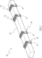
- a packaging system (assembly) 10, for the transportation of an elongate product 12, is illustrated in Figures 1 to 12 of the accompanying drawings.
- the packaging system 10 finds use in transporting elongate product such as plastic, metal or composite extrusions, timber or any manufactured products having length and requiring transportation, and bundles or groups thereof.
- Figure 1 shows the packaging system in use with four cleat units 15 evenly distributed along the length of the product 12 to evenly bear the load of the product.
- the cleat units 15 can be spaced as appropriate to, for example, accommodate a particular elongate product 12 or to account for different types of cleat material. For example: heavier elongate products 12 may require a greater number of cleat units 15 to be used in order to adequately support its weight; a product 12 with non-uniform weight distribution may require non-uniform cleat unit 15 distribution along its length; and cleat units 15 made from lighter materials may warrant the use of more cleat units 15 in order to properly support the elongate product 12, without damage to either the elongate product 12 or cleat units 15.
- the spacing between cleats will therefore vary depending on the nature, including weight, of the product to be loaded and according to specific end user requirements. However, by way of example only, the spacing between cleat units carrying timber, centre to centre, could be between 1.0m and 1.5m, such as 1.2m.
- Product 12 extends through a space 14 in the cleat units 15 formed by a lower cleat 16, an upper cleat 18 and side cleats 20 that interconnect the lower and upper cleats. Straps 17 extending at least part way around the assembly of the cleat unit assist in tightly securing the cleat unit around the product 12.
- the side cleats 20 are height adjustable, and able to be set at variable heights, to vary the spacing between the upper and lower cleats and thereby adjust to the correct height correlating to the product 12 being supported.
- the advantage of this system is that it is easy to use, it reliably provides a very stable package for transportation and it can be re-used to suit a variety of different applications and products.
- the cleat units 15 can form a substantially rigid structure so that there is little or no relative movement of the lower and upper cleats 16, 18 during transportation. Thus shunting of cleat units 15 against each other can be avoided.
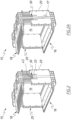
- the side cleats (side supports) 20 are substantially planar supports interconnected between the upper and lower cleats that telescopically slide relative to each other to extend and retract between a shortened, retracted position to an extended full height position by way of at least two sliding parts that substantially overlap in the retracted position but extend to elongate with less overlap in the extended position.
- a first, lower sliding part 21 having a receiving recess 24 to receive a second, upper sliding part 22.
- Figure 2 illustrates the cleat unit 15 in an almost retracted position with upper part 22 nested within recess 24 of lower part 21.
- Figure 3 illustrates the upper part 22 extended upwardly from lower part 21 to thereby raise the height of side cleat 20 and increase the area of space 14 through which a product extends and is supported. Accordingly, products of various heights may be supported by the same cleat units 15.
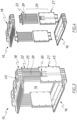
- Figure 4 illustrates the components of a cleat unit 15 in exploded view.
- Figures 7, 8 and 9 illustrate the lower sliding part 21 and
- Figures 10 and 11 illustrate the upper sliding part 22.
- Longitudinal guide spines 23 in receiving recess 24 engage with longitudinal guide grooves 25 on upper part 22 to maintain a sliding motion between the two parts.
- Guide grooves 25 are formed by further spines 32 that alternate with the lower part's guide spines 23.
- the lower part 21 includes two connectors 26 with detents (resilient pawls) 27 provided at a lower end thereof for interconnecting the side cleat to the lower cleat 16.
- Lower cleat 16 has upwardly facing connection pockets 28a that correspond in shape and size to receive the connectors 26. The resilience of detents 27 against stops 29 in the pockets 28a create a snaplock connection between lower sliding part 21 and lower cleat 16.
- Upper sliding part 22 includes two locators 31 upstanding from an upper end of upper part 22 for locating into a downwardly facing corresponding connection pocket 28b.
- Pockets 28a and 28b are the same pocket structure where 28a is open upwardly to receive a connection (from the lower part 21) and 28b is open downwardly to receive another connection (from the upper part 22).
- the pockets 28a and 28b may be open through to each other, with a stop or constriction in the middle to prevent one interconnected component from extending right through the pocket, or the pockets may be closed, being blind pockets.
- the side cleats are height adjustable and are set to the selected height by the application of a force on one or both side cleats, where that force is directed inwardly of the cleat unit.
- the force acts on a locking mechanism 30 that obstructs the adjustability function of the side cleat 20.
- the locking mechanism includes a resilient member, in the form of a tongue (resilient pawl) 33, on the lower sliding part 21 being urged against the upper sliding part 22 and to engage therewith to obstruct the sliding motion between the parts.
- Tongue 33 is integrally formed with the housing structure of lower part 21 at an upper central portion thereof and is defined by two lateral slits 34 cut down into an outer face 35 of the lower part 21 from an upper edge 36 defining the opening to the receiving recess 24.
- the tongue obtains its resilience by way of the shape of the slits 34 and/or the properties of the material used for the side cleats, which may be a mouldable plastic or formed from metal.
- the tongue has a first locking component that engages with a second locking component on the portion of the upper sliding part 22 that slides adjacent and close to the tongue.
- an inner side of the tongue specifically has ratchet-shaped teeth 38.
- the teeth are ramped on one side up to an acute angle at the apex of the tooth where a perpendicular surface 41 of each tooth then turns back to meet the tongue at a perpendicular angle.
- the tongue's teeth 38 are configured to engage with correspondingly ratchet-shaped, but in a reverse direction, teeth 39 provided in rows across a central panel that runs down the length of the upper portion 22 (see Figure 10 ). Teeth 39 of the upper part are similarly profiled to the tongue's teeth 38.
- Force on the tongue 33 may be applied by various means but the force needs to be one that can be held, indefinitely. Such force could be applied by using fasteners such as locking clips or clasps, but in the embodiment described herein the force is applied by the strapping that extends at least partly around the upper, lower and side cleats and that is used to secure the cleat unit tightly around the product. As shown in Figure 2A the strapping 17 is adapted to extend over tongue 33 so that when the strapping is tightened the tightening force on the strap will in turn press inwardly against the tongue forcing the tongue's teeth 38 against, and into contact with, the teeth 39 of the upper part and thereby fix, or lock, the spacing between the upper and lower cleats by preventing any movement within the side cleat.
- the strapping 17 used can be any kind of reliable strapping used to secure cargo including metal or plastic straps, or straps made from woven or knitted fibres.
- the inward force onto tongue 33 need not be exclusively applied by using straps, but could be applied by other force applying mechanism, such as stretch film wrap applied using spiral wrapping equipment.
- the tension of the wrapped film in the instance would apply a holding/locking force on the tongue that will lock the extension of the side cleat and stop sliding.
- Still another alternative could be to provide the cleat unit with a sliding or hinged latch that can be moved to lock movement of the side cleat extension by acting as a detent.
- the outer facing side of the tongue 33 includes a series of outwardly raised ribs 43. These ribs protruding outwardly are to encourage purchase of the straps on the tongue and increase the force on the tongue to move it inward into locking engagement with the upper part.
- strapping guides 45 in the form of strap channels provided in both the upper cleat 18 and the side cleats 20.
- the strap channels 45 can be in the form of lateral ridges or a sunken recess provided on a wall of the cleat part (as provided on the side cleat 20) or in the form of a continuous channel between structural components of the cleat (as provided on the upper surface of the upper cleat 18.
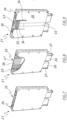
- Cleat component 13 that is both the upper cleat 18 and the lower cleat 16.
- Cleat component 13 is formed such that in one orientation it acts as a lower cleat and in an opposite, upside down orientation, it acts as an upper cleat.
- Cleat component 13 includes a substantially flat surface on one planar side, and a rib-strengthened surface with a strap channel 45 on the opposite planar side.
- Four pockets 28a and 28b are provided near the shorter edges of the rectangular cleat structure, and as discussed earlier, on one side the pockets 28a receive a lower end of the side cleats 15 and on the other side the pockets 28b receive an upper end of the side cleats 15.
- the cleat component 13 when the flat surface is assembled facing up, the cleat component 13 will be the lower cleat 16 supporting the load of the product 12, and when the flat surface is assembled facing downwardly, the cleat component will be the upper cleat 18 restraining the product from above.
- the cleat component 13 has a cantilevered reinforcing planar extension 50 that extends out one side of the component.
- the reinforcing extension increases the effective length of the cleat unit and provides greater protection to the product.
- the reinforcing extension 50 may be formed integrally with the cleat component 13 as shown in the drawings, for example by moulding, or it may be a separate part that is attached or inserted after manufacture. Also shown (see Figure 6 ) is the cleat component having a side entry 48 adapted to receive an additional reinforcement extension (not shown) as a separate component that extends from an opposite side of the cleat component to integral extension 50.
- the cleat units 15 may be made of a suitable material that will be sufficiently durable to withstand repeated use and, preferably, lightweight to not add to the weight of the packaging.
- the cleat units can be made of moulded plastics, where the side cleats may be made of the same or a different material to the upper and lower cleats.
- the side cleats could be made of a composite material (plastic/graphite/metal) that would increase the strength of the side cleat for holding greater loads.
- Figure 12 illustrates the packaging system 10 stacked in a double, one on top, configuration with an top cleat unit 52 and a bottom cleat unit 53.
- the cleat components are formed to be positively stackable, to make storage and transportation easier and more space saving.
- strapping 17 can extend around the entire perimeter of the bundled stack with the strapping passing over both tongues of the top and bottom cleat units and when tensioned will apply an inward force on the tongues, inward in the direction of the centre of each cleat unit. The inward force will lock the height of the packaged assemblies and keep them securely in place ready for lifting, transportation and further stacking without shunting and with a reduction in the incidence of damage due to poor or inappropriate packaging.
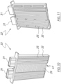
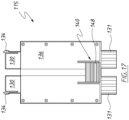
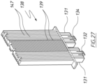
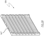
- FIG. 13 to 28 of the accompanying drawings there is schematically depicted a packaging assembly 110.
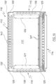
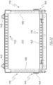
- the assembly 110 provides a generally rectangular (including square) frame 112 that surrounds an aperture 111.
- a plurality of elongated products such as aluminium or plastic extrusions, extend longitudinally through the aperture 111 so as to be retained as a bundle by the assembly 110.
- the frame 112 includes an upper cleat 113 and a lower cleat 114.
- the cleats 113 and 114 are longitudinally parallel, transversely spaced and substantially co-extensive.
- the frame 112 also includes a pair of side supports 115 that are generally upwardly oriented, generally parallel but transversely spaced, and extend between the cleats 113 and 114.
- the side supports 115 are also generally co-extensive.
- the side supports 115 are longitudinally elongated so as to have a longitudinal length 117, the length 117 is adjustable.
- the area of the aperture 111 can be adjusted to suit the bundle size of articles to be transported by the assembly 110.
- Each end extremity of the cleat 113 is provided with a pair of sockets 120, with each end extremity of the cleat 114 being provided with a pair of sockets 125.
- each side support 115 includes a pair of upper projections 130 and a pair of lower projections 131.
- Each pair of lower projections 131 is slidably received within a pair of associated sockets 125.
- each pair of upper projections 130 is received within an associated pair of the sockets 120, with at least one of the projections 130 having a resilient pawl 134 that provides for insertion of the projections 130, but resiliently moves to engagement with a surface 135 of the associated socket 120, to retain the support 115 fixed to the upper cleat 113.
- each side support 115 includes a pair of upper projections 130 and a pair of lower projections 131. Each pair of upper projections 130 is received within a pair of associated sockets 120.
- each pair of lower projections 131 is received within an associated pair of the sockets 125, with at least one of projections 131 having a resilient pawl 134 that provides for insertion of the projections 131, but resiliently moves to engagement with a surface 135 of the associated socket 125, to retain the support 115 fixed to the lower cleat 114.
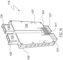
- the cleat 114 is provided with a pair of elongated pads 127 that are resilient, and engages the product being transported to at least aid in inhibiting damage to the product, and to aid in inhibiting movement of the product.
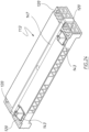
- Each support 115 includes a base 136 that includes the projections 130, and that co-operates with a cover member 126 to provide a passage 137 that telescopically receives a support part 138.
- the lower end extremity of the part 138 includes the projections 131.
- the longitudinal length 117 of each support 115 is provided by sliding longitudinal telescopic movement between the base 136 and the associated part 138.
- the cover 126, base 136 and part 138 have co-operating ridges and grooves 147 that engage to guide the part 138 in its sliding movement.
- the part 138 has a plurality of "ratchet" teeth 139 that extend longitudinally transverse of the longitudinally direction of extension of the part 138, and that are engaged by a resilient pawl 140 of the base 136.
- the pawl 140 has at least one tooth 141 that engages the teeth 139 to retain the base 136 at a desired position relative to the part 138, that is retaining the base 136 and part 138 so as to provide a desired longitudinal length 117.
- the base 136 and part 138 can be moved relative to each other by a user providing a compressive force or a tensioning force to the base 136 and part 138 to cause elongation or contraction of the support 115.
- the tooth 141 moves into and out of engagement with selected teeth 139, by resilient deformation of the pawl 140.
- Each support 115 is an assembly including a base 136, cover member 126 and part 138 slidably associated therewith.
- Each base 136 is fixed to one of the cover members 125 so that the two supports 115 each have the passage 124.
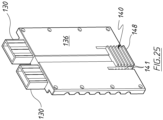
- a strap (such as the strap 17 of Figure 2A ) 145 is placed about the assembly 110 so that the strap 145, upon tensioning pushes, pushes on the projections 148 of the on the pawls 140, to retain the pawls 140 securely engaged with a selected one or more of the teeth 139 so that the length 117 is then fixed.
- a releasable fastener or catch would retain the strap 145 tensioned.
- the strap 145 upon being released, would enable elongation of the side supports 115 and removal of the products.
- the cleats 113 and 114 also urged toward each other, so that the length 117 is adjusted by contractions of the supports 115, so that the bundle is securely held between the cleats 113 and114.
- the strap 145 is held in position by being located in slots 146 and 147 of the cleats 113 and 114 and side supports 115.
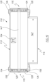
- the lower cleat 114 has a lateral projecting flange 142.
- the flanges 142 can be located so as to be spaced to suit the tines of a forklift vehicle.
- Each of the flanges 142 has projecting from its lower surface a plurality of resilient pads 146 that engage a supporting surface.
- the upper cleat 113 is provided with at least one projection 143.
- the projection 143 engages within a selected one of the sockets 144 to provide for stacking of the assemblies 110. That is, each assembly 110 has a projection 143 and socket 144 to provide for stacking of the assemblies 110.
- the projections 143 and sockets 144 inhibit relative movement between stacked assemblies 110.
- the projection 143 is generally central of the cleat 113. In the embodiment of Figure 18 , there are two projections 143, each adjacent a respective end extremity of the cleat 113, so as to be adjacent the sockets 120 and supports 115.
- the cleats 113 and 114, and supports 115 are formed by being moulded of plastics material.
- the cleats 113 and 114 are each integrally formed.
- each pawl 140 is moulded integral with the remainder of its associated supporting base 136.
- each part 138 is integrally formed so as to have the pawls 132 and 134 integrally formed with the remainder of the part 138.
- a particular advantage of the above described preferred embodiment is that the length (height) 117 is adjustable, to adjust to the height of the bundle to be transported by the assembly 110.
Landscapes
- Engineering & Computer Science (AREA)
- Mechanical Engineering (AREA)
- Package Frames And Binding Bands (AREA)
Claims (11)
- Verpackungsanordnung (10) mit:eine obere Klampe (18);eine untere Klampe (16);eine erste und eine zweite Seitenstütze (20), wobei sich jede Seitenstütze (20) zwischen der oberen und der unteren Klampe (15) erstreckt und daran so befestigt ist, dass die obere Klampe (18) und die untere Klampe (16) um einen Abstand voneinander beabstandet sind, wobei die Klampe (15) und die Seitenstützen (20) einen allgemein rechteckigen Rahmen (112) bilden, der eine Öffnung (111) umgibt, in der das zu transportierende Produkt (12) angeordnet werden soll; und wobei sowohl die erste Seitenstütze als auch die zweite Seitenstütze (20) ein unteres Gleitteil (21) und ein oberes Gleitteil (22) aufweisen, die teleskopisch so konfiguriert sind, dass sie sich zwischen einer ausgefahrenen Position und einer eingezogenen Position bewegen können, um eine Einstellung einer Längslänge der ersten Seitenstütze und der zweiten Seitenstütze (20) zu ermöglichen, die sich zwischen der oberen Leiste (18) und der unteren Leiste (16) erstreckt, dadurch gekennzeichnet, dass der untere gleitende Teil (21) und der obere gleitende Teil (22) in ihrer Position durch einen Verriegelungsmechanismus (30) verriegelbar sind, der eine Vielzahl von Ratschenzähnen (38, 39) und eine elastische Sperrklinke (27, 33, 134, 140) umfasst, wobei die elastische Sperrklinke (27, 33, 134, 140) so konfiguriert ist, dass sie in Eingriff mit den Ratschenzähnen (38, 39) gedrückt wird, so dass der Abstand zwischen dem oberen Stollen (18) und dem unteren Stollen (16) beibehalten wird.
- Baugruppe nach Anspruch 1, bei der sich die elastische Sperrklinke (27, 33, 134, 140) bei ausreichender Krafteinwirkung entlang der Sperrzähne (38, 39) bewegt, um eine Einstellung des Abstands zwischen der oberen und der unteren Stollenplatte (15) zu ermöglichen.
- Baugruppe nach Anspruch 1 oder 2, wobei der obere Gleitteil (22) jeder Seitenstütze (20) die Sperrzähne (38, 39) und der untere Gleitteil (21) jeder Seitenstütze (20) die elastische Sperrklinke (27, 33, 134, 140) aufweist.
- Die Baugruppe nach einem der Ansprüche 1 bis 3,
wobei die Verpackungs
Anordnung (10) einen Gurt (17) aufweist, der um die obere Klampe (18), die untere Klampe (16) und die erste und zweite Seitenstütze (20) verläuft, wobei der Gurt (17) so gespannt werden kann, dass die Spannung mit der elastischen Klinke (27, 33, 134, 140) der ersten und zweiten Seitenstütze (20) mit den Ratschenzähnen (38, 39) der ersten und zweiten Seitenstütze (20) in Eingriff kommt, um die Seitenstützen (20) auf einer Längslänge fixiert zu halten. - Verpackungsanordnung (10) nach Anspruch 1, wobei die obere Klampe (18) und die untere Klampe (16) jeweils gegenüberliegende Enden aufweisen und jede Seitenstütze (20) ein oberes und ein unteres Ende hat, wobei die Enden Vorsprünge (130, 131) und Buchsen (120) aufweisen, so dass jeder Vorsprung (130, 131) in einer entsprechenden Buchse aufgenommen wird, um die Seitenstützen (20) an den Klampen (15) zu sichern.
- Baugruppe nach Anspruch 5, bei der das Endende der oberen Leiste (18) und der unteren Leiste (16) mit mindestens einer der Buchsen (120) versehen ist und das Endende jeder Seitenstütze (20) mit einem der Vorsprünge (130, 131) versehen ist, die in einer entsprechenden der Buchsen (120) aufgenommen werden.
- Baugruppe nach einem der Ansprüche 5, wobei die obere Stollenplatte (18) und die untere Stollenplatte (16) jeweils gegenüberliegende Enden aufweisen und jede Seitenstütze (20) ein oberes und ein unteres Ende hat, wobei die Enden Vorsprünge und Buchsen aufweisen, so dass jeder Vorsprung in einer entsprechenden Buchse (120) aufgenommen wird, um die Seitenstützen (20) an den Stollenplatten (15) zu befestigen.
- Baugruppe nach Anspruch 7, bei der jedes Stollenendstück mit mindestens einer der Buchsen (120) versehen ist und jedes Seitenstützenendstück mit einem der Vorsprünge (130, 131) versehen ist, die in einer entsprechenden der Buchsen (120) aufgenommen werden.
- Baugruppe nach Anspruch 5 oder 8, wobei mindestens einer der Vorsprünge (130, 131) eine elastische Sperrklinke (27, 33, 134, 140) aufweist, die mindestens eine der Seitenstützen (20) lösbar an einer zugehörigen der Stollen (15) befestigt.
- Baugruppe nach Anspruch 9, bei der jede federnde Sperrklinke (27, 33, 134, 140) in die obere Klampe (18) eingreift.
- Baugruppe nach Anspruch 9, bei der jede federnde Sperrklinke (27, 33, 134 und 140) in die untere Klampe (16) eingreift.
Applications Claiming Priority (2)
| Application Number | Priority Date | Filing Date | Title |
|---|---|---|---|
| AU2016903616A AU2016903616A0 (en) | 2016-09-08 | Packaging System | |
| PCT/AU2017/000175 WO2018045408A1 (en) | 2016-09-08 | 2017-08-23 | Packaging assembly |
Publications (3)
| Publication Number | Publication Date |
|---|---|
| EP3515844A1 EP3515844A1 (de) | 2019-07-31 |
| EP3515844A4 EP3515844A4 (de) | 2020-07-01 |
| EP3515844B1 true EP3515844B1 (de) | 2024-02-07 |
Family
ID=61561232
Family Applications (1)
| Application Number | Title | Priority Date | Filing Date |
|---|---|---|---|
| EP17847801.2A Active EP3515844B1 (de) | 2016-09-08 | 2017-08-23 | Verpackungsanordnung |
Country Status (4)
| Country | Link |
|---|---|
| US (1) | US11377295B2 (de) |
| EP (1) | EP3515844B1 (de) |
| AU (1) | AU2017219010B2 (de) |
| WO (1) | WO2018045408A1 (de) |
Families Citing this family (5)
| Publication number | Priority date | Publication date | Assignee | Title |
|---|---|---|---|---|
| JP2023552564A (ja) * | 2020-12-08 | 2023-12-18 | アースエコ グローバル ピーティーワイ リミテッド | パイプフレーム |
| CN113044392A (zh) * | 2021-03-18 | 2021-06-29 | 上海外高桥造船有限公司 | 一种管束堆放托架 |
| CN113310367B (zh) * | 2021-06-01 | 2024-03-05 | 西安昆仑工业装备配套有限公司 | 轻量化弹药包装装置 |
| USD1112832S1 (en) | 2022-11-16 | 2026-02-10 | Eartheco Global Pty Ltd | Frame member |
| WO2025075562A1 (en) * | 2023-10-05 | 2025-04-10 | Htn Plast Plasti̇k Sanayi̇ Ve Ti̇caret Anoni̇m Şi̇rketi̇ | Packaging system |
Family Cites Families (22)
| Publication number | Priority date | Publication date | Assignee | Title |
|---|---|---|---|---|
| US441607A (en) * | 1890-11-25 | William ii | ||
| US1082848A (en) * | 1913-01-22 | 1913-12-30 | Percy W Dargin | Adjustable binder. |
| US2730259A (en) * | 1951-03-10 | 1956-01-10 | Leo M Harvey | Packing case |
| US4042107A (en) * | 1975-02-24 | 1977-08-16 | Ici United States Inc. | Returnable roll shipping container |
| US4378923A (en) * | 1981-07-09 | 1983-04-05 | Nippon Kokan Kabushiki Kaisha | Binding device for elongated pipes |
| DE3928320A1 (de) * | 1989-08-26 | 1991-03-14 | Drilltec Patents & Tech | Vorrichtung zur lagerung und zum transport von rohren |
| US5058746A (en) * | 1989-10-04 | 1991-10-22 | Morgan Iv Robert L | Pallet container structure II |
| DE4138882A1 (de) * | 1991-11-27 | 1993-06-09 | Drilltec Patents & Technologies Co., Inc., Houston, Tex., Us | Vorrichtung zum transport und zum stapeln von zylindrischen gegenstaenden, wie gasflaschen, rohren usw. |
| US6484897B1 (en) * | 1995-02-13 | 2002-11-26 | Amcad Holdings Limited | Containers with variable volume |
| US6032801A (en) * | 1997-01-17 | 2000-03-07 | Jupille Design Incorporated | Pallet system |
| US5803257A (en) * | 1996-11-07 | 1998-09-08 | Menasha Corporation | Panel crating structure |
| DE29702638U1 (de) * | 1997-02-15 | 1997-04-03 | Thread Guard Technology Ltd., Gibraltar | Vorrichtung zur Abstützung von Rohren |
| GB2345282B (en) * | 1998-12-30 | 2001-09-05 | Kim Jum Gyu | Variable height container for vessel |
| DE29906754U1 (de) * | 1999-04-16 | 1999-07-08 | Erbslöh AG, 42553 Velbert | Rahmen zur Bildung einer stapelbaren Lager- und Transportvorrichtung für langgestreckte Gegenstände |
| GB9911010D0 (en) * | 1999-05-13 | 1999-07-14 | Payne John M | Improvements in ans relating to conveyor belts |
| US7080864B2 (en) * | 2002-05-03 | 2006-07-25 | Drilltec Patents & Technologies Company, Inc. | Apparatus for shipping and storing elongated members |
| DE102010048176B3 (de) * | 2010-10-13 | 2012-01-05 | Thread Guard Technology Ltd. | Vorrichtung zur Fixierung einer Mehrzahl von Rohren relativ zueinander bei deren Lagerung und Transport |
| AU2011100549C4 (en) * | 2011-05-13 | 2015-12-24 | Capral Limited | Packaging System |
| AU2013100033B4 (en) * | 2013-01-14 | 2015-11-12 | Whites Group Pty Ltd | Pack for fence posts or other elongate objects |
| EP3083424B1 (de) * | 2013-11-04 | 2017-12-27 | Nalto Marketing Ltd. | Versendungsvorrichtung |
| US9938073B2 (en) * | 2014-07-01 | 2018-04-10 | Sea Box International | Pipe intermodal logistics system |
| CN205366509U (zh) * | 2015-06-15 | 2016-07-06 | 浙江天衣机械有限公司 | 一种用于锁定钢管支架组件的侧向拉杆机构 |
-
2017
- 2017-08-23 EP EP17847801.2A patent/EP3515844B1/de active Active
- 2017-08-23 AU AU2017219010A patent/AU2017219010B2/en active Active
- 2017-08-23 WO PCT/AU2017/000175 patent/WO2018045408A1/en not_active Ceased
- 2017-08-23 US US16/292,640 patent/US11377295B2/en active Active
Also Published As
| Publication number | Publication date |
|---|---|
| WO2018045408A9 (en) | 2018-10-11 |
| EP3515844A1 (de) | 2019-07-31 |
| US20190322444A1 (en) | 2019-10-24 |
| WO2018045408A1 (en) | 2018-03-15 |
| AU2017219010B2 (en) | 2023-07-20 |
| EP3515844A4 (de) | 2020-07-01 |
| AU2017219010A1 (en) | 2018-03-22 |
| US11377295B2 (en) | 2022-07-05 |
Similar Documents
| Publication | Publication Date | Title |
|---|---|---|
| EP3515844B1 (de) | Verpackungsanordnung | |
| US6367631B1 (en) | Locking system for stacking boxes as well as a stacking box system | |
| US4453471A (en) | Panel retaining clamp for collapsible pallet containers | |
| US8176856B2 (en) | Loading ledge | |
| US3567068A (en) | Collapsible pallet | |
| WO2018007778A1 (en) | A transport and storage system | |
| US1714692A (en) | Package | |
| EP1836096B1 (de) | Verfahren zum festbinden von verpackten waren an einer palette | |
| US20210130058A1 (en) | Wrapping device having corner protectors for securing and supporting palletized materials | |
| JP6535838B2 (ja) | 積載物拘束具及び梱包方法 | |
| US7618221B2 (en) | Corner and bulkhead protector | |
| NZ734884A (en) | Packaging assembly | |
| US20100206200A1 (en) | Pallet system | |
| KR20160100763A (ko) | 롤 제품용 운반 및 포장장치 및 이를 이용한 롤 제품용 파렛트 | |
| GB2581814A (en) | Tessellatable container, system and method | |
| CN104870326A (zh) | 用于在运输托盘上的箱式结构体的角件 | |
| JP6573067B2 (ja) | 積載物拘束具 | |
| KR101633581B1 (ko) | 포장 용기 | |
| JP5863621B2 (ja) | 運搬用支持台 | |
| US1982437A (en) | Shipping crate | |
| BE1028399B1 (nl) | Universele doos met geoptimaliseerde afmetingen voor transport van fittingen | |
| SU1060545A1 (ru) | Многооборотный поддон дл хранени и транспортировки пакетов грузов | |
| RU136790U1 (ru) | Контейнер (варианты) | |
| AU593107B2 (en) | Improved shipping containers | |
| DE202025105686U1 (de) | Formkörper |
Legal Events
| Date | Code | Title | Description |
|---|---|---|---|
| STAA | Information on the status of an ep patent application or granted ep patent |
Free format text: STATUS: THE INTERNATIONAL PUBLICATION HAS BEEN MADE |
|
| PUAI | Public reference made under article 153(3) epc to a published international application that has entered the european phase |
Free format text: ORIGINAL CODE: 0009012 |
|
| STAA | Information on the status of an ep patent application or granted ep patent |
Free format text: STATUS: REQUEST FOR EXAMINATION WAS MADE |
|
| 17P | Request for examination filed |
Effective date: 20190408 |
|
| AK | Designated contracting states |
Kind code of ref document: A1 Designated state(s): AL AT BE BG CH CY CZ DE DK EE ES FI FR GB GR HR HU IE IS IT LI LT LU LV MC MK MT NL NO PL PT RO RS SE SI SK SM TR |
|
| AX | Request for extension of the european patent |
Extension state: BA ME |
|
| DAV | Request for validation of the european patent (deleted) | ||
| DAX | Request for extension of the european patent (deleted) | ||
| A4 | Supplementary search report drawn up and despatched |
Effective date: 20200604 |
|
| RIC1 | Information provided on ipc code assigned before grant |
Ipc: B65B 27/10 20060101ALI20200528BHEP Ipc: B65G 1/04 20060101AFI20200528BHEP Ipc: B65G 57/18 20060101ALI20200528BHEP |
|
| STAA | Information on the status of an ep patent application or granted ep patent |
Free format text: STATUS: EXAMINATION IS IN PROGRESS |
|
| 17Q | First examination report despatched |
Effective date: 20220602 |
|
| GRAP | Despatch of communication of intention to grant a patent |
Free format text: ORIGINAL CODE: EPIDOSNIGR1 |
|
| STAA | Information on the status of an ep patent application or granted ep patent |
Free format text: STATUS: GRANT OF PATENT IS INTENDED |
|
| INTG | Intention to grant announced |
Effective date: 20230818 |
|
| GRAS | Grant fee paid |
Free format text: ORIGINAL CODE: EPIDOSNIGR3 |
|
| GRAA | (expected) grant |
Free format text: ORIGINAL CODE: 0009210 |
|
| STAA | Information on the status of an ep patent application or granted ep patent |
Free format text: STATUS: THE PATENT HAS BEEN GRANTED |
|
| AK | Designated contracting states |
Kind code of ref document: B1 Designated state(s): AL AT BE BG CH CY CZ DE DK EE ES FI FR GB GR HR HU IE IS IT LI LT LU LV MC MK MT NL NO PL PT RO RS SE SI SK SM TR |
|
| REG | Reference to a national code |
Ref country code: GB Ref legal event code: FG4D |
|
| REG | Reference to a national code |
Ref country code: CH Ref legal event code: EP |
|
| REG | Reference to a national code |
Ref country code: IE Ref legal event code: FG4D |
|
| REG | Reference to a national code |
Ref country code: DE Ref legal event code: R096 Ref document number: 602017079034 Country of ref document: DE |
|
| REG | Reference to a national code |
Ref country code: LT Ref legal event code: MG9D |
|
| REG | Reference to a national code |
Ref country code: NL Ref legal event code: FP |
|
| PG25 | Lapsed in a contracting state [announced via postgrant information from national office to epo] |
Ref country code: IS Free format text: LAPSE BECAUSE OF FAILURE TO SUBMIT A TRANSLATION OF THE DESCRIPTION OR TO PAY THE FEE WITHIN THE PRESCRIBED TIME-LIMIT Effective date: 20240607 |
|
| PG25 | Lapsed in a contracting state [announced via postgrant information from national office to epo] |
Ref country code: LT Free format text: LAPSE BECAUSE OF FAILURE TO SUBMIT A TRANSLATION OF THE DESCRIPTION OR TO PAY THE FEE WITHIN THE PRESCRIBED TIME-LIMIT Effective date: 20240207 |
|
| PG25 | Lapsed in a contracting state [announced via postgrant information from national office to epo] |
Ref country code: GR Free format text: LAPSE BECAUSE OF FAILURE TO SUBMIT A TRANSLATION OF THE DESCRIPTION OR TO PAY THE FEE WITHIN THE PRESCRIBED TIME-LIMIT Effective date: 20240508 |
|
| REG | Reference to a national code |
Ref country code: AT Ref legal event code: MK05 Ref document number: 1655239 Country of ref document: AT Kind code of ref document: T Effective date: 20240207 |
|
| PG25 | Lapsed in a contracting state [announced via postgrant information from national office to epo] |
Ref country code: RS Free format text: LAPSE BECAUSE OF FAILURE TO SUBMIT A TRANSLATION OF THE DESCRIPTION OR TO PAY THE FEE WITHIN THE PRESCRIBED TIME-LIMIT Effective date: 20240507 Ref country code: HR Free format text: LAPSE BECAUSE OF FAILURE TO SUBMIT A TRANSLATION OF THE DESCRIPTION OR TO PAY THE FEE WITHIN THE PRESCRIBED TIME-LIMIT Effective date: 20240207 |
|
| PG25 | Lapsed in a contracting state [announced via postgrant information from national office to epo] |
Ref country code: ES Free format text: LAPSE BECAUSE OF FAILURE TO SUBMIT A TRANSLATION OF THE DESCRIPTION OR TO PAY THE FEE WITHIN THE PRESCRIBED TIME-LIMIT Effective date: 20240207 |
|
| PG25 | Lapsed in a contracting state [announced via postgrant information from national office to epo] |
Ref country code: AT Free format text: LAPSE BECAUSE OF FAILURE TO SUBMIT A TRANSLATION OF THE DESCRIPTION OR TO PAY THE FEE WITHIN THE PRESCRIBED TIME-LIMIT Effective date: 20240207 |
|
| PG25 | Lapsed in a contracting state [announced via postgrant information from national office to epo] |
Ref country code: RS Free format text: LAPSE BECAUSE OF FAILURE TO SUBMIT A TRANSLATION OF THE DESCRIPTION OR TO PAY THE FEE WITHIN THE PRESCRIBED TIME-LIMIT Effective date: 20240507 Ref country code: NO Free format text: LAPSE BECAUSE OF FAILURE TO SUBMIT A TRANSLATION OF THE DESCRIPTION OR TO PAY THE FEE WITHIN THE PRESCRIBED TIME-LIMIT Effective date: 20240507 Ref country code: LT Free format text: LAPSE BECAUSE OF FAILURE TO SUBMIT A TRANSLATION OF THE DESCRIPTION OR TO PAY THE FEE WITHIN THE PRESCRIBED TIME-LIMIT Effective date: 20240207 Ref country code: IS Free format text: LAPSE BECAUSE OF FAILURE TO SUBMIT A TRANSLATION OF THE DESCRIPTION OR TO PAY THE FEE WITHIN THE PRESCRIBED TIME-LIMIT Effective date: 20240607 Ref country code: HR Free format text: LAPSE BECAUSE OF FAILURE TO SUBMIT A TRANSLATION OF THE DESCRIPTION OR TO PAY THE FEE WITHIN THE PRESCRIBED TIME-LIMIT Effective date: 20240207 Ref country code: GR Free format text: LAPSE BECAUSE OF FAILURE TO SUBMIT A TRANSLATION OF THE DESCRIPTION OR TO PAY THE FEE WITHIN THE PRESCRIBED TIME-LIMIT Effective date: 20240508 Ref country code: FI Free format text: LAPSE BECAUSE OF FAILURE TO SUBMIT A TRANSLATION OF THE DESCRIPTION OR TO PAY THE FEE WITHIN THE PRESCRIBED TIME-LIMIT Effective date: 20240207 Ref country code: ES Free format text: LAPSE BECAUSE OF FAILURE TO SUBMIT A TRANSLATION OF THE DESCRIPTION OR TO PAY THE FEE WITHIN THE PRESCRIBED TIME-LIMIT Effective date: 20240207 Ref country code: BG Free format text: LAPSE BECAUSE OF FAILURE TO SUBMIT A TRANSLATION OF THE DESCRIPTION OR TO PAY THE FEE WITHIN THE PRESCRIBED TIME-LIMIT Effective date: 20240207 Ref country code: AT Free format text: LAPSE BECAUSE OF FAILURE TO SUBMIT A TRANSLATION OF THE DESCRIPTION OR TO PAY THE FEE WITHIN THE PRESCRIBED TIME-LIMIT Effective date: 20240207 |
|
| PG25 | Lapsed in a contracting state [announced via postgrant information from national office to epo] |
Ref country code: PL Free format text: LAPSE BECAUSE OF FAILURE TO SUBMIT A TRANSLATION OF THE DESCRIPTION OR TO PAY THE FEE WITHIN THE PRESCRIBED TIME-LIMIT Effective date: 20240207 Ref country code: PT Free format text: LAPSE BECAUSE OF FAILURE TO SUBMIT A TRANSLATION OF THE DESCRIPTION OR TO PAY THE FEE WITHIN THE PRESCRIBED TIME-LIMIT Effective date: 20240607 |
|
| PG25 | Lapsed in a contracting state [announced via postgrant information from national office to epo] |
Ref country code: SE Free format text: LAPSE BECAUSE OF FAILURE TO SUBMIT A TRANSLATION OF THE DESCRIPTION OR TO PAY THE FEE WITHIN THE PRESCRIBED TIME-LIMIT Effective date: 20240207 Ref country code: PT Free format text: LAPSE BECAUSE OF FAILURE TO SUBMIT A TRANSLATION OF THE DESCRIPTION OR TO PAY THE FEE WITHIN THE PRESCRIBED TIME-LIMIT Effective date: 20240607 Ref country code: PL Free format text: LAPSE BECAUSE OF FAILURE TO SUBMIT A TRANSLATION OF THE DESCRIPTION OR TO PAY THE FEE WITHIN THE PRESCRIBED TIME-LIMIT Effective date: 20240207 Ref country code: LV Free format text: LAPSE BECAUSE OF FAILURE TO SUBMIT A TRANSLATION OF THE DESCRIPTION OR TO PAY THE FEE WITHIN THE PRESCRIBED TIME-LIMIT Effective date: 20240207 |
|
| PG25 | Lapsed in a contracting state [announced via postgrant information from national office to epo] |
Ref country code: DK Free format text: LAPSE BECAUSE OF FAILURE TO SUBMIT A TRANSLATION OF THE DESCRIPTION OR TO PAY THE FEE WITHIN THE PRESCRIBED TIME-LIMIT Effective date: 20240207 |
|
| PG25 | Lapsed in a contracting state [announced via postgrant information from national office to epo] |
Ref country code: SM Free format text: LAPSE BECAUSE OF FAILURE TO SUBMIT A TRANSLATION OF THE DESCRIPTION OR TO PAY THE FEE WITHIN THE PRESCRIBED TIME-LIMIT Effective date: 20240207 |
|
| PG25 | Lapsed in a contracting state [announced via postgrant information from national office to epo] |
Ref country code: CZ Free format text: LAPSE BECAUSE OF FAILURE TO SUBMIT A TRANSLATION OF THE DESCRIPTION OR TO PAY THE FEE WITHIN THE PRESCRIBED TIME-LIMIT Effective date: 20240207 Ref country code: EE Free format text: LAPSE BECAUSE OF FAILURE TO SUBMIT A TRANSLATION OF THE DESCRIPTION OR TO PAY THE FEE WITHIN THE PRESCRIBED TIME-LIMIT Effective date: 20240207 |
|
| PG25 | Lapsed in a contracting state [announced via postgrant information from national office to epo] |
Ref country code: SK Free format text: LAPSE BECAUSE OF FAILURE TO SUBMIT A TRANSLATION OF THE DESCRIPTION OR TO PAY THE FEE WITHIN THE PRESCRIBED TIME-LIMIT Effective date: 20240207 |
|
| PG25 | Lapsed in a contracting state [announced via postgrant information from national office to epo] |
Ref country code: SM Free format text: LAPSE BECAUSE OF FAILURE TO SUBMIT A TRANSLATION OF THE DESCRIPTION OR TO PAY THE FEE WITHIN THE PRESCRIBED TIME-LIMIT Effective date: 20240207 Ref country code: SK Free format text: LAPSE BECAUSE OF FAILURE TO SUBMIT A TRANSLATION OF THE DESCRIPTION OR TO PAY THE FEE WITHIN THE PRESCRIBED TIME-LIMIT Effective date: 20240207 Ref country code: RO Free format text: LAPSE BECAUSE OF FAILURE TO SUBMIT A TRANSLATION OF THE DESCRIPTION OR TO PAY THE FEE WITHIN THE PRESCRIBED TIME-LIMIT Effective date: 20240207 Ref country code: EE Free format text: LAPSE BECAUSE OF FAILURE TO SUBMIT A TRANSLATION OF THE DESCRIPTION OR TO PAY THE FEE WITHIN THE PRESCRIBED TIME-LIMIT Effective date: 20240207 Ref country code: DK Free format text: LAPSE BECAUSE OF FAILURE TO SUBMIT A TRANSLATION OF THE DESCRIPTION OR TO PAY THE FEE WITHIN THE PRESCRIBED TIME-LIMIT Effective date: 20240207 Ref country code: CZ Free format text: LAPSE BECAUSE OF FAILURE TO SUBMIT A TRANSLATION OF THE DESCRIPTION OR TO PAY THE FEE WITHIN THE PRESCRIBED TIME-LIMIT Effective date: 20240207 |
|
| REG | Reference to a national code |
Ref country code: DE Ref legal event code: R097 Ref document number: 602017079034 Country of ref document: DE |
|
| PG25 | Lapsed in a contracting state [announced via postgrant information from national office to epo] |
Ref country code: IT Free format text: LAPSE BECAUSE OF FAILURE TO SUBMIT A TRANSLATION OF THE DESCRIPTION OR TO PAY THE FEE WITHIN THE PRESCRIBED TIME-LIMIT Effective date: 20240207 |
|
| PLBE | No opposition filed within time limit |
Free format text: ORIGINAL CODE: 0009261 |
|
| STAA | Information on the status of an ep patent application or granted ep patent |
Free format text: STATUS: NO OPPOSITION FILED WITHIN TIME LIMIT |
|
| PG25 | Lapsed in a contracting state [announced via postgrant information from national office to epo] |
Ref country code: IT Free format text: LAPSE BECAUSE OF FAILURE TO SUBMIT A TRANSLATION OF THE DESCRIPTION OR TO PAY THE FEE WITHIN THE PRESCRIBED TIME-LIMIT Effective date: 20240207 |
|
| 26N | No opposition filed |
Effective date: 20241108 |
|
| REG | Reference to a national code |
Ref country code: CH Ref legal event code: PL |
|
| PG25 | Lapsed in a contracting state [announced via postgrant information from national office to epo] |
Ref country code: LU Free format text: LAPSE BECAUSE OF NON-PAYMENT OF DUE FEES Effective date: 20240823 |
|
| PG25 | Lapsed in a contracting state [announced via postgrant information from national office to epo] |
Ref country code: SI Free format text: LAPSE BECAUSE OF FAILURE TO SUBMIT A TRANSLATION OF THE DESCRIPTION OR TO PAY THE FEE WITHIN THE PRESCRIBED TIME-LIMIT Effective date: 20240207 Ref country code: MC Free format text: LAPSE BECAUSE OF FAILURE TO SUBMIT A TRANSLATION OF THE DESCRIPTION OR TO PAY THE FEE WITHIN THE PRESCRIBED TIME-LIMIT Effective date: 20240207 Ref country code: CH Free format text: LAPSE BECAUSE OF NON-PAYMENT OF DUE FEES Effective date: 20240831 |
|
| REG | Reference to a national code |
Ref country code: BE Ref legal event code: MM Effective date: 20240831 |
|
| PG25 | Lapsed in a contracting state [announced via postgrant information from national office to epo] |
Ref country code: BE Free format text: LAPSE BECAUSE OF NON-PAYMENT OF DUE FEES Effective date: 20240831 |
|
| PG25 | Lapsed in a contracting state [announced via postgrant information from national office to epo] |
Ref country code: IE Free format text: LAPSE BECAUSE OF NON-PAYMENT OF DUE FEES Effective date: 20240823 |
|
| PGFP | Annual fee paid to national office [announced via postgrant information from national office to epo] |
Ref country code: NL Payment date: 20250718 Year of fee payment: 9 |
|
| PGFP | Annual fee paid to national office [announced via postgrant information from national office to epo] |
Ref country code: DE Payment date: 20250718 Year of fee payment: 9 |
|
| PGFP | Annual fee paid to national office [announced via postgrant information from national office to epo] |
Ref country code: GB Payment date: 20250829 Year of fee payment: 9 |
|
| PGFP | Annual fee paid to national office [announced via postgrant information from national office to epo] |
Ref country code: FR Payment date: 20250829 Year of fee payment: 9 |
|
| PG25 | Lapsed in a contracting state [announced via postgrant information from national office to epo] |
Ref country code: CY Free format text: LAPSE BECAUSE OF FAILURE TO SUBMIT A TRANSLATION OF THE DESCRIPTION OR TO PAY THE FEE WITHIN THE PRESCRIBED TIME-LIMIT; INVALID AB INITIO Effective date: 20170823 |
|
| PG25 | Lapsed in a contracting state [announced via postgrant information from national office to epo] |
Ref country code: HU Free format text: LAPSE BECAUSE OF FAILURE TO SUBMIT A TRANSLATION OF THE DESCRIPTION OR TO PAY THE FEE WITHIN THE PRESCRIBED TIME-LIMIT; INVALID AB INITIO Effective date: 20170823 |