EP3515628B1 - Verfahren und werkzeugmaschine zum bearbeiten von plattenförmigen werkstücken, insbesondere von blechen - Google Patents
Verfahren und werkzeugmaschine zum bearbeiten von plattenförmigen werkstücken, insbesondere von blechen Download PDFInfo
- Publication number
- EP3515628B1 EP3515628B1 EP17777857.8A EP17777857A EP3515628B1 EP 3515628 B1 EP3515628 B1 EP 3515628B1 EP 17777857 A EP17777857 A EP 17777857A EP 3515628 B1 EP3515628 B1 EP 3515628B1
- Authority
- EP
- European Patent Office
- Prior art keywords
- workpiece
- tool
- axis
- workpiece part
- upper tool
- Prior art date
- Legal status (The legal status is an assumption and is not a legal conclusion. Google has not performed a legal analysis and makes no representation as to the accuracy of the status listed.)
- Active
Links
Images


Classifications
-
- B—PERFORMING OPERATIONS; TRANSPORTING
- B21—MECHANICAL METAL-WORKING WITHOUT ESSENTIALLY REMOVING MATERIAL; PUNCHING METAL
- B21D—WORKING OR PROCESSING OF SHEET METAL OR METAL TUBES, RODS OR PROFILES WITHOUT ESSENTIALLY REMOVING MATERIAL; PUNCHING METAL
- B21D45/00—Ejecting or stripping-off devices arranged in machines or tools dealt with in this subclass
- B21D45/003—Ejecting or stripping-off devices arranged in machines or tools dealt with in this subclass in punching machines or punching tools
-
- B—PERFORMING OPERATIONS; TRANSPORTING
- B21—MECHANICAL METAL-WORKING WITHOUT ESSENTIALLY REMOVING MATERIAL; PUNCHING METAL
- B21D—WORKING OR PROCESSING OF SHEET METAL OR METAL TUBES, RODS OR PROFILES WITHOUT ESSENTIALLY REMOVING MATERIAL; PUNCHING METAL
- B21D28/00—Shaping by press-cutting; Perforating
- B21D28/02—Punching blanks or articles with or without obtaining scrap; Notching
- B21D28/06—Making more than one part out of the same blank; Scrapless working
-
- B—PERFORMING OPERATIONS; TRANSPORTING
- B21—MECHANICAL METAL-WORKING WITHOUT ESSENTIALLY REMOVING MATERIAL; PUNCHING METAL
- B21D—WORKING OR PROCESSING OF SHEET METAL OR METAL TUBES, RODS OR PROFILES WITHOUT ESSENTIALLY REMOVING MATERIAL; PUNCHING METAL
- B21D43/00—Feeding, positioning or storing devices combined with, or arranged in, or specially adapted for use in connection with, apparatus for working or processing sheet metal, metal tubes or metal profiles; Associations therewith of cutting devices
- B21D43/28—Associations of cutting devices therewith
- B21D43/287—Devices for handling sheet or strip material
Definitions
- the invention relates to a method and a machine tool for machining plate-shaped workpieces, in particular sheet metal.
- Such a machine tool is from the EP 2 527 058 B1
- This document discloses a machine tool in the form of a press for machining workpieces, wherein an upper tool is provided on a lifting device which can be moved relative to a workpiece to be machined along a lifting axis in the direction of the workpiece and in the opposite direction.
- a lower tool is provided in the lifting axis and opposite the upper tool and is positioned towards a lower side.
- a lifting drive device for a lifting movement of the upper tool is controlled by a wedge gear.
- the lifting drive device with the upper tool arranged thereon can be moved along a positioning axis.
- the lower tool is moved synchronously with the upper tool.
- a machine tool in which, in the form of a press for machining workpieces, an upper tool is provided on a lifting device and can be moved along the lifting axis in the direction of the workpiece and a lower tool and in the opposite direction.
- a table segment provided in the workpiece support for the workpiece to be machined can be lowered or pivoted downwards in order to eject the workpiece part separated from the workpiece.
- the workpiece part falls downwards due to a tilting movement and slides along the table segment in the ejection direction.
- the tool can then be picked up by a collecting container or the like.
- a processing machine for processing plate-shaped workpieces is known. This has a transfer device in a working area by means of which the The workpiece part can be removed from the workpiece support after separation from the workpiece. Subsequently, subsequent processing is carried out using a subsequent processing tool on the workpiece part removed from the workpiece support. After subsequent processing, the workpiece part is then returned to the workpiece support located in the working area of the machine arrangement using this transfer device. Before the workpiece part stored on the workpiece support and the subsequent processing product stored on the workpiece support are removed from the working area of the processing machine together with the workpiece support using a removal device.
- the invention is based on the object of proposing a method and a machine tool for machining workpieces, by means of which increased process reliability is enabled when removing at least one workpiece part separated from the workpiece.
- a method for machining plate-shaped workpieces in particular sheet metal, in which an upper tool, which is movable along a lifting axis with a lifting drive device in the direction of a workpiece to be machined with the upper tool and in the opposite direction, is positioned with at least one motor drive arrangement along an upper positioning axis running perpendicular to the lifting axis, and in which a lower tool, which is aligned with the upper tool, is positioned with at least one motor drive arrangement along a lower positioning axis running perpendicular to the lifting axis of the upper tool.
- the workpiece lies on a workpiece support for machining.
- the upper and lower tools are moved in the interior of a machine frame, wherein the motor drive arrangements for moving the upper and lower tools are controlled by a controller.
- at least one workpiece part is separated from the workpiece.
- the upper tool is moved outside of a spatial volume that extends above the severed workpiece part and is formed by at least a predetermined part of the base area of the workpiece part in the workpiece plane and a perpendicular to the workpiece part in the direction of the upper positioning axis, or by a predetermined part of the base area and an area outside the base area of the workpiece part in the workpiece plane and a perpendicular to the workpiece part in the direction of the upper positioning axis.
- the severed workpiece is removed.
- This method for removing the at least one workpiece part severed from the workpiece has the advantage of increased process reliability. A moving movement of the workpiece part is not necessary to remove the severed workpiece part. After being separated or cut free, the workpiece part can remain in its position on the workpiece support until it is removed. In addition, an increased removal height is created within the machine frame of the machine tool above the workpiece part to be removed. This allows even larger workpieces to be removed reliably. This eliminates the risk of collision when removing the workpiece from the upper tool.
- the at least one workpiece part is removed with a gripping device, which is moved above the workpiece and is positioned in the spatial volume before gripping.
- a collision-free lifting movement of the gripping device can also be carried out to the extent It must be ensured that at least one workpiece part can be lifted relative to a workpiece or residual skeleton that may remain on the workpiece support in order to then, for example, guide the workpiece part out of the spatial volume in a plane above the workpiece and transfer it to an unloading position.
- An alternative embodiment of the method provides that before a table segment provided in the workpiece support is lowered to discharge the at least one workpiece part separated from the workpiece, the upper tool is moved outside the spatial volume.
- This has the advantage that a tilting movement of the workpiece part resting on it and to be discharged is possible when the table segment is lowered in the workpiece support, and the workpiece part can be discharged without collision.
- a workpiece edge opposite in the discharge direction can perform a tilting movement.
- the workpiece part can perform a free tilting movement when the table segment is lowered and is not hindered by the upper tool located above or the stripper of the upper tool. This also prevents damage to the upper side of the workpiece part during discharge.
- the upper tool is moved along the upper positioning axis outside the spatial volume of the workpiece part before the lowering movement of the table segment is initiated.
- a simple movement of the upper tool allows it to be quickly transferred to an area adjacent to the tilting area of the workpiece part, thus enabling short cycle times for collision-free removal.
- the lower tool after a final separating cut or free cutting of a residual connection of the workpiece part to the workpiece and during the lowering of the
- the table segment is positioned stationary in the last working position for ejecting the workpiece part. This also increases process reliability. After the workpiece part has been separated or cut free from the workpiece, the workpiece part, which is loose from the workpiece, remains in its position on the workpiece support until the table segment is lowered. This prevents the workpiece part from becoming caught or shifted above or below the workpiece.
- the table segment is pivoted and lowered about a rotational axis aligned parallel to the upper positioning axis of the upper tool. This allows the table segment to be directly connected to the workpiece support surface, enabling safe removal after the table segment, which is also referred to as a pivoting parts flap, is lowered.
- the spatial volume can be formed by a tilting area of a workpiece edge of the workpiece part that is opposite to the ejection direction when the workpiece part is ejected.
- a length of the workpiece part to be ejected is released during ejection, the length of which includes the length of the lowerable table segment, and a distance between the workpiece support surface and an interfering edge of the machine frame arranged above it is determined.
- the lateral movement of the upper tool increases the length of the workpiece parts to be ejected and expands the range of workpiece parts to be manufactured.
- a machine tool which is preferably intended to carry out the method described above.
- This A machine tool comprises an upper tool which is movable along a lifting axis by means of a lifting drive device in the direction of a workpiece to be machined with the upper tool and in the opposite direction, and which is positionable by means of at least one motor drive arrangement along an upper positioning axis running perpendicular to the lifting axis, and which has a lower tool which is aligned with the upper tool and can be positioned by means of at least one motor drive arrangement along a lower positioning axis which is aligned perpendicular to the lifting axis of the upper tool.
- This machine tool has a machine frame, within the frame interior of which the upper and lower tools can be moved.
- the workpiece to be machined lies on a workpiece support of the machine tool.
- the workpiece machine has a control system by means of which the motor drive arrangements for moving the upper and lower tools can be controlled.
- the control system can control the travel movement of the upper tool along the upper positioning axis and the travel movement of the lower tool along the lower positioning axis, each independently of one another.
- the upper tool can be positioned outside a spatial volume, wherein the spatial volume is defined at least by a predetermined portion of the base area of the severed workpiece part in the workpiece plane and a perpendicular to the workpiece part in the direction of the upper positioning axis, or by a predetermined portion of the base area and an area outside the base area of the workpiece part in the workpiece plane and a perpendicular to the workpiece part in the direction of the upper positioning axis.
- the machine tool has a gripping device with at least one holding element and that At least one holding element can be moved into the spatial volume for gripping and removing at least one workpiece part.
- a gripping device can be part of a handling device, thereby enabling automation during the removal and any subsequent processing of the workpiece parts.
- the gripping device is arranged on a machine frame, preferably an upper horizontal frame leg, and in particular the holding elements are movable with at least one linear axis of a linear drive.
- the gripping device can be provided on a handling device, which is designed as a standalone module and is assigned to a workpiece support. This also enables automated handling of the workpiece parts.
- the machine tool can be provided with a table segment in the workpiece support, which can be lowered relative to a workpiece support for discharging a workpiece part.
- a movement of the upper tool relative to the lower tool can be controlled so that the upper tool is positioned outside the spatial volume of the workpiece part to be discharged.
- the upper tool can be moved outside of a collision area by lowering the table segment.
- the lowering of the table segment can cause a tilting movement of the workpiece part so that a workpiece edge lagging in the discharging direction is lifted relative to the workpiece support before it is discharged downwards.
- the movement space of the lagging workpiece edge forms the tilting area or the spatial volume.
- the upper tool does not hinder such a tilting movement, since it is positioned outside the collision zone or tilt zone. This allows for collision-free ejection. Furthermore, damage to the upper side of the workpiece part being ejected, especially the good part, is avoided.
- a preferred embodiment of the machine tool provides that the table segment is pivotably mounted along a rotational axis. This rotational axis is aligned parallel to the upper positioning axis. This allows the upper tool to be moved outside the tilting range by controlling a travel movement of the upper tool along the upper positioning axis.
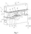
- FIG. 1 A machine tool 1 is shown, which is designed as a punching press.
- This machine tool 1 comprises a supporting structure with a closed machine frame 2.
- This comprises two horizontal frame legs 3, 4 and two vertical frame legs 5 and 6.
- the machine frame 2 encloses a frame interior 7, which forms the working area of the machine tool 1 with an upper tool 11 and a lower tool 9.
- the machine tool 1 is used for machining plate-shaped workpieces 10, which for the sake of simplicity are Figure 1 are not shown and can be arranged in the frame interior 7 for processing purposes.
- a workpiece 10 to be machined is placed on a workpiece support 8 provided in the frame interior 7.
- the lower tool 9, for example in the form of a punching die, is mounted in a recess of the workpiece support 8 on the lower horizontal frame leg 4 of the machine frame 2.
- This punching die can be provided with a die opening.
- the upper tool 11 designed as a punching punch, plunges into the die opening of the lower tool designed as a punching die.
- the upper tool 11 is fixed in a tool holder at a lower end of a ram 12.
- the ram 12 is part of a lifting drive device 13, by means of which the upper tool 11 can be moved in a lifting direction along a lifting axis 14.
- the lifting axis 14 runs in the direction of the Z-axis of the coordinate system of a Figure 1 indicated numerical control 15 of machine tool 1.
- Perpendicular to the lifting axis 14, the lifting drive device 13 can be moved along a positioning axis 16 in the direction of the double arrow.
- the positioning axis 16 runs in the direction of the Y-axis of the coordinate system of the numerical control 15.
- the lifting drive device 13, which holds the upper tool 11, is moved along the positioning axis 16 by means of a motor drive 17.
- the movement of the ram 12 along the stroke axis 14 and the positioning of the stroke drive device 13 along the positioning axis 16 are carried out by means of a motor drive 17 in the form of a drive arrangement 17, in particular a spindle drive arrangement, with a drive spindle 18 running in the direction of the positioning axis 16 and firmly connected to the machine frame 2.
- the stroke drive device 13 is guided during movements along the positioning axis 16 on three guide rails 19 of the upper frame leg 3, of which Figure 1 two guide rails 19 can be seen.
- the remaining guide rail 19 runs parallel to the visible guide rail 19 and is spaced from it in the X-axis direction of the coordinate system of the numerical control 15.
- Guide shoes 20 of the lifting drive device 13 run on the guide rails 19.
- the mutual engagement of the guide rail 19 and the guide shoes 20 is such that this connection between the guide rails 19 and the guide shoes 20 can also absorb a load acting in the vertical direction. Accordingly, the lifting device 13 is suspended from the machine frame 2 via the guide shoes 20 and the guide rails 19. Another component of the lifting drive device 13 is a wedge gear 21, by means of which the position of the upper tool 11 relative to the lower tool 9 can be adjusted.
- the lower tool 9 is mounted so as to be movable along a lower positioning axis 25.
- This lower positioning axis 25 runs in the direction of the Y-axis of the coordinate system of the numerical control 15.
- the lower positioning axis 25 is preferably aligned parallel to the upper positioning axis 16.
- the lower tool 9 can be moved directly along the lower positioning axis 16 using a motor drive arrangement 26 along the positioning axis 25.
- the lower tool 9 can also be provided on a lifting drive device 27, which can be moved along the lower positioning axis 25 by means of the motor drive arrangement 26.
- This drive arrangement 26 is preferably designed as a spindle drive arrangement.
- the lower lifting drive device 27 can correspond in structure to the upper lifting drive device 13.
- the motor drive arrangement 26 can also correspond to the motor drive arrangement 17.
- the lower lifting drive device 27 is slidably mounted on guide rails 19 assigned to the lower horizontal frame leg 4.
- Guide shoes 20 of the lifting drive device 27 run on the guide rails 19, so that the connection between the guide rails 19 and the guide shoes 20 on the lower tool 9 can also absorb a load acting in the vertical direction. Accordingly, the lifting drive device 27 is also suspended via the guide shoes 20 and the guide rails 19 on the machine frame 2 and spaced from the guide rails 19 and guide shoes 20 of the upper lifting drive device 13.
- the lifting drive device 27 can also include a wedge gear 21, by means of which the position or height of the lower tool 9 can be adjusted along the Z-axis.
- the numerical control 15 allows both the motor drives 17 for moving the upper tool 11 along the upper positioning axis 16 and the motor drive(s) 26 for moving the lower tool 9 along the lower positioning axis 25 to be controlled independently of one another.
- the upper and lower tools 11, 9 can be moved synchronously in the Y-axis of the coordinate system.
- independent movement of the upper and lower tools 11, 9 can also be controlled in different directions.
- This independent movement of the upper and lower tools 11, 9 can be controlled simultaneously.
- the upper and lower tools 11, 9 can also be designed in a variety of ways for machining the workpieces 10.
- a component of the lifting drive device 13 is the wedge gear 21, which is Figure 2
- the wedge gear 21 comprises two drive-side wedge gear elements 122, 123, as well as two output-side wedge gear elements 124, 125.
- the latter are structurally combined into a structural unit in the form of an output-side double wedge 126.
- the plunger 12 is rotatably mounted about the stroke axis 14 on the output-side double wedge 126.
- a motorized rotary drive device 128 is housed in the output-side double wedge 126 and moves the plunger 12 along the stroke axis 14 as required. Both a left-hand and a right-hand rotation of the plunger 12 is possible according to the double arrow in Figure 2 possible.
- a tappet bearing 129 is shown schematically.
- the tappet bearing 129 allows low-friction rotary movements of the tappet 12 about the stroke axis 14.
- the tappet bearing 129 supports the tappet 12 in the axial direction and accordingly transfers loads acting on the tappet 12 in the direction of the stroke axis 14 to the output-side double wedge 126.
- the output-side double wedge 126 is formed by a wedge surface 130, as well as limited by a wedge surface 131 of the output-side gear element 125.
- Wedge surfaces 130, 131 of the output-side wedge gear elements 124, 125 are opposed by wedge surfaces 132, 133 of the drive-side wedge gear elements 122, 123.
- Longitudinal guides 134, 135 guide the drive-side wedge gear element 122 and the output-side wedge gear element 124, as well as the drive-side wedge gear element 123 and the output-side wedge gear element 125, so that they can move relative to one another in the direction of the Y-axis, i.e., in the direction of the positioning axis 16 of the lifting drive device 13.
- the drive-side wedge gear element 122 has a motor drive unit 138, and the drive-side wedge gear element 123 has a motor drive unit 139. Both drive units 138, 139 together form the spindle drive arrangement 17.
- the motor drive units 138, 139 have in common the Figure 1 shown drive spindle 18 and the lifting drive device 13, 27 mounted on the machine frame 2 and consequently on the supporting structure side.
- the drive-side wedge gear elements 122, 123 are operated by the motor drive units 138, 139 in such a way that they move, for example, toward one another along the positioning axis 16, resulting in a relative movement between the drive-side wedge gear elements 122, 123 on the one hand and the output-side wedge gear elements 124, 125 on the other.
- the output-side double wedge 126 and the tappet 12 mounted thereon are moved downward along the stroke axis 14.
- the punching punch mounted on the ram 12 for example as an upper tool 11, performs a working stroke and in the process machines a workpiece 10 mounted on the workpiece support 28, 29 or the workpiece support 8.
- the ram 12 is in turn raised or moved upwards along the stroke axis 14.
- the previously described lifting drive device 13 according to Figure 2 is preferably constructed identically as the lower lifting drive device 27 and holds the lower tool 9.
- FIG 3 a schematic diagram of a possible lifting movement of the ram 12 is shown.
- the diagram shows a stroke profile along the Y-axis and the Z-axis.
- an oblique lifting movement of the lifting ram 12 downwards towards the workpiece 10 can be controlled, as shown by the first straight line A.
- the ram 12 can, for example, be lifted vertically, as shown by the straight line B.
- This is followed, for example, by an exclusive travel movement along the Y-axis according to the straight line C in order to position the ram 12 for a new working position relative to the workpiece 10.
- the previously described work sequence can be repeated, for example. If the workpiece 10 is moved on the workpiece support surface 28, 29 for a subsequent machining step, a travel movement along the straight line C can also be omitted.
- the diagram in Figure 3 The possible stroke movement of the ram 12 on the upper tool 11 shown is preferably combined with a stationary lower tool 9.
- the lower tool 9 is positioned within the machine frame 2 in such a way that at the end of a working stroke of the upper tool 11, the upper and lower tools 11, 9 assume a defined position.
- This exemplary superimposed stroke curve can be controlled for both the upper tool 11 and the lower tool 9. Depending on the machining of the workpiece 10, a superimposed stroke movement of the upper tool and/or lower tool 11, 9 can be controlled.
- Figure 4 is a schematic diagram showing a stroke movement of the plunger 12 according to the exemplary line D along a Y-axis and a Z-axis.
- a The stroke movement of the ram 12 can follow a curved or arcuate path by controlling a superposition of the travel movements in the Y and Z directions accordingly by the controller 15.
- Such a flexible superposition of the travel movements in the X and Z directions allows specific machining tasks to be solved.
- the control of such a curved path can be provided for the upper tool 11 and/or lower tool 9.
- FIG 5 is a schematic view of the machine tool 1 according to Figure 1 shown.
- a workpiece support 28, 29 extends laterally on each of the machine frame 2 of the machine tool 1.
- the workpiece support 28 can, for example, be assigned to a loading station (not shown in detail), through which unmachined workpieces 10 are placed onto the workpiece support 28.
- Adjacent to the workpiece support 28, 29, a feed device 22 is provided, which comprises a plurality of grippers 23 for gripping the workpiece 10 placed on the workpiece support 28.
- the feed device 22 can also be controlled so that it can be moved in the Y direction. This allows a free movement of the workpiece 10 in the XY plane.
- the workpiece 10 can be moved by the feed device 22 both in the X direction and counter to the X direction. This movement of the workpiece 10 can be adapted to a movement of the upper tool 11 and lower tool 9 in and against the Y direction for the respective machining task.
- another workpiece support 29 is provided on the machine frame 2. This can, for example, be assigned to an unloading station. Alternatively, the loading and unloading of the unmachined workpiece 10 and the machined workpiece 10 with workpieces 81 can also be assigned to the same workpiece support 28, 29.
- the machine tool 1 can further comprise a laser processing device 201, in particular a laser cutting machine, which is shown only schematically in a plan view in Figure 5 is shown.
- This laser processing device 201 can be designed, for example, as a CO2 laser cutting machine.
- the laser processing device 201 comprises a laser source 202, which generates a laser beam 203, which is guided by means of a schematically illustrated beam guide 204 to a laser processing head, in particular laser cutting head 206, and focused therein.
- the laser beam 204 is then directed through a cutting nozzle perpendicular to the surface of the workpiece 10 in order to process the workpiece 10.
- the laser beam 203 acts on the workpiece 10 at the processing location, in particular the cutting location, preferably together with a process gas jet.
- the cutting point at which the laser beam 203 impinges on the workpiece 10 is adjacent to the processing location of the upper tool 11 and lower tool 9.
- the laser cutting head 206 is movable by a linear drive 207 with a linear axis system at least in the Y direction, preferably in the Y and Z directions.
- This linear axis system which accommodates the laser cutting head 206, can be assigned to the machine frame 2, attached to it, or integrated therein.
- a beam passage opening can be provided in the workpiece support 28 below a working area of the laser cutting head 206.
- a beam collection device for the laser beam 21 can be provided below the beam passage opening.
- the beam passage opening and, if applicable, the beam collection device can also be designed as a single structural unit.
- the laser processing device 201 can alternatively also have a solid-state laser as the laser source 202, the radiation of which is guided to the laser cutting head 206 by means of a fiber optic cable.
- the workpiece support 28, 29 can extend directly to the workpiece support 8, which at least partially surrounds the lower tool 9. Within a space resulting therebetween The lower tool 9 can be moved along the lower positioning axis 25 in and against the Y direction.
- a machined workpiece 10 rests on the workpiece support 28, in which a workpiece part 81 has been cut free from a cutting gap 83, for example by punching or laser beam machining, except for a residual connection 82.
- This residual connection holds the workpiece 81 in the workpiece 10 or the remaining residual skeleton.
- the workpiece 10 is positioned by the feed device 22 to the upper and lower tools 11, 9 for a punching and ejection step.
- the residual connection 82 is severed by a punching stroke of the upper tool 11 to the lower tool 9.
- the workpiece part 81 can be ejected, for example, by partially lowering the workpiece support 8.
- the cut-out workpiece part 81 can be transferred back to the workpiece support 28 or to the workpiece support 29 in order to unload the workpiece part 81 and the residual skeleton.
- Smaller workpiece parts 81 can also be ejected through an opening in the lower tool 9, if necessary.
- FIG 6 A simplified schematic view of an end face of the upper drive assembly 17 and the lower drive assembly 26 with a workpiece 10 arranged therebetween is shown. This view is taken in the Y direction of the upper and lower drive assemblies 17, 26.
- the Figure 7 shows a further schematic side view of the drive arrangements 17, 26 according to Figure 6 in the X direction.
- the upper and lower drive assemblies 17, 26 are aligned with each other, for example, with respect to an upper lifting axis 14 and a lower lifting axis 30.
- at least one workpiece part 81 is at least partially cut free and fixed to the workpiece 10 via a residual connection 82 or completely separated from the workpiece 10.
- the workpiece part 81 has, for example, a rectangular contour.
- a spatial volume 220 is formed by at least a predetermined portion of the base area of the workpiece part 81 and a perpendicular thereto in the direction of the upper positioning axis 16, which spatial volume is limited in height by a distance between the workpiece 10 and an underside of the upper horizontal frame leg 3.
- the spatial volume 220 can also be formed by the base area of the workpiece part 81 and a perpendicular thereto in the direction of the upper positioning axis 16.
- the spatial volume 220 can also be determined by the base area and a lateral extension beyond the base area of the workpiece 81 and a perpendicular thereto in the direction of the upper positioning axis 16.
- the spatial volume 220 can also be formed by a predetermined portion of the base area of the workpiece part 81 and by a lateral extension beyond the base area of the workpiece part 81 and a perpendicular thereto.
- the lateral extension extends in and against the upper positioning axis 16, along which the upper tool 11 can be moved.
- the upper tool 11 is positioned outside the spatial volume 220, so that this spatial volume 220 above the workpiece 10 and below the upper horizontal frame leg 3 is freely accessible and can be used for the removal of the workpiece part 81.
- the removal height between the workpiece plane and a bottom side of the upper horizontal frame leg 3 is reduced compared to if the upper tool 11 remains in the spatial volume 220, as is shown in the Figures 6 and 7 shown, increased.
- This free space volume 220 enables a collision-free removal of the workpiece part 81 by discharging the workpiece part 81 downwards via a table segment 285, as described below in the Figures 8 to 12 or by removal by means of a gripping device 292, as described below with reference to Figures 13 and 14 described.
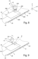
- FIG 8 A simplified schematic representation of a workpiece 10 resting on the workpiece support 28, 29 is shown, which is being machined by an upper and lower tool 9, 11.
- the workpiece 10 is moved in and against the X direction by the grippers 23 to create a cutting gap 83.
- the upper and lower tools 9, 11 are moved accordingly in and against the Y direction along the upper and lower positioning axes 16, 25.
- the workpiece support 28 comprises a table segment 285, which forms part of the workpiece support 28.
- This table segment 285 can be lowered relative to the workpiece support surface 28 for discharging workpiece parts 81.
- the table segment 285 is pivotally mounted about a rotation axis 286, which is aligned parallel to the positioning axis 16, 25.
- the table segment 285 preferably extends over the entire width of the workpiece support 28, 29 in the Y direction.
- the table segment 285 is flush with the adjacent workpiece support 8 due to the pivotable connection, so that after a lowering movement, the workpiece part 81 can be discharged downwards, as is the case, for example, in Figure 12
- the discharge direction is shown by arrows 287.
- the last cutting cut can be in the Y-axis.
- the last cutting cut is in an X-axis, that is, starting from the beginning of a cutting gap 83 according to arrow 288 ( Figure 8 ) and a counterclockwise production of the cutting gap 83, for example, a workpiece edge 289 opposite the table segment 285 with respect to the rotation axis 286 is cut.
- This workpiece edge 289 is oriented, for example, in the Y direction.
- the upper tool 11 is moved along the upper positioning axis 16.
- the lower tool 9 is held stationary relative to the lower positioning axis 25 in the last working position for separating or cutting free the workpiece part 81.
- the upper tool 11 is moved by a distance relative to the lower tool 9 ( Figure 9 ), so that it is positioned outside the spatial volume 220. This has the advantage that during a tilting movement of the workpiece edge 289 about the rotation axis 286 after the lowering of the table segment 285, the workpiece part 81 does not collide with the upper tool 11.
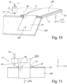
- a first phase of the discharge after lowering the table segment 285 is shown in perspective in Figure 10 and in a front view in Figure 11
- the workpiece 10 resting on the table segment 85 which has a section with a final workpiece edge 289 that lies outside the support surface of the table segment 285, undergoes a tilting movement when the table segment 285 is lowered.
- the workpiece edge 289 opposite in the discharge direction 287 is pivoted relative to a workpiece plane in the direction of the upper frame leg 3.
- Such a maximum tilting movement of the workpiece part 81 is Figure 11 shown.
- the upper tool 11 Due to the offset of the position axes 35 of the upper tool 11 relative to the position axis 48 of the lower tool 9, the upper tool 11 is positioned outside the collision area or the tilting area of the workpiece part 81. This allows the tilting movement to be carried out unhindered within the free space 220, and the workpiece part 81 can be discharged downwards.
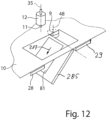
- a final phase of the discharge process is in Figure 12
- the workpiece edge 289 has already been lowered and is below the workpiece plane of the workpiece 10.
- the table segment 285 can be closed again in order to create a closed workpiece support 28. and the upper and lower tools 11, 9 are moved into position to the workpiece 10 for a new machining operation.
- FIG 13 is an alternative embodiment of the machine tool to Figure 1 and 5
- This machine tool 1 differs from the Figure 1 and Figure 5 that instead of or in addition to the laser processing device 201 according to Figure 5 a gripping device 292 is provided on the machine frame 2, which is controlled to be movable above the workpiece 10 via a linear drive 207, which is also arranged on the upper horizontal frame leg 3.
- the laser processing device 201 can be provided on an opposite side wall on the horizontal frame leg 3 of the machine tool 1 and can have a similar structure as in Figure 5 have.
- the linear drive 207 for the gripping device 292 can have a horizontal linear axis 293, along which a vertical linear axis 294 is movable along the Y-direction.
- the gripping device 292 is arranged on the vertical linear axis 294 and comprises holding elements 295 facing the workpiece 10.
- the holding elements 295 can be arranged and/or controlled individually or in groups. These holding elements 295 can be, for example, magnetic suction cups, vacuum suction cups, or electro-adhesion suction cups.
- the individual groups of holding elements 295 can also be controlled individually in order to successively remove one or more workpiece parts 81 separated from the workpiece 10.
- the gripping device 292 is positioned with at least one of the holding elements 295 in the spatial volume 220 above the workpiece part 81 to be removed in order to remove at least one workpiece part 81.
- the upper tool 11 has been moved outside the spatial volume 220 before the holding elements 295 are positioned in the spatial volume 220, as can be seen from a schematically enlarged view according to Figure 14 In this perspective view according to Figure 14 the side of the machine frame 2 opposite the gripping device 292 is shown.
- the upper tool 11 is positioned outside the spatial volume 220 of the severed workpiece part 81 by the upper drive assembly 17. This allows the holding elements 295 to be retracted and positioned unhindered into a position above the workpiece part 81 or the workpiece parts 81 in the spatial volume 220.
- the lateral movement of the upper tool 11 before the removal of the at least one workpiece part 81 increases the removal height between the workpiece 10 and an underside of the upper horizontal frame leg 3.
- the at least one workpiece part 81 can rest motionless on the workpiece support 28, 29 after separation.
- the lower tool 9 remains stationary outside the spatial volume 220 during the movement of the upper tool 11 in the position in which the last separating cut for the workpiece part 81 took place.
- the at least one holding element 295 is lowered.
- the at least one workpiece part 81 is gripped, subsequently triggering a lifting movement of the holding elements 295 in the Z direction.
- the workpiece part 81 is positioned above the workpiece plane of the workpiece 10.
- the gripping device 292 with its holding elements 295 can be guided out of the spatial volume 220, and the workpiece parts can be transferred to an unloading position.
- Such a gripping device 292 can increase automation.
- the gripping device 292 and the linear drive 207 with the at least one linear axis 293, 294 are designed as an independent handling device.
- This handling device can be assigned to one of the two workpiece supports 28, 29 and positioned adjacent to or adjacent thereto.
- the gripping device 292 of such a handling device can be designed analogously to the Figure 13 and 14 described gripping device 292 for removing the workpiece parts 81 can be used and controlled.
Landscapes
- Engineering & Computer Science (AREA)
- Mechanical Engineering (AREA)
- Punching Or Piercing (AREA)
- Machine Tool Units (AREA)
- Turning (AREA)
- Laser Beam Processing (AREA)
Applications Claiming Priority (3)
| Application Number | Priority Date | Filing Date | Title |
|---|---|---|---|
| DE102016118175.7A DE102016118175B4 (de) | 2016-09-26 | 2016-09-26 | Werkzeugmaschine und Verfahren zum Bearbeiten von plattenförmigen Werkstücken |
| DE102016120151.0A DE102016120151A1 (de) | 2016-10-21 | 2016-10-21 | Verfahren und Werkzeugmaschine zum Bearbeiten von plattenförmigen Werkstücken, insbesondere von Blechen |
| PCT/EP2017/074283 WO2018055178A1 (de) | 2016-09-26 | 2017-09-26 | Verfahren und werkzeugmaschine zum bearbeiten von plattenförmigen werkstücken, insbesondere von blechen |
Publications (2)
| Publication Number | Publication Date |
|---|---|
| EP3515628A1 EP3515628A1 (de) | 2019-07-31 |
| EP3515628B1 true EP3515628B1 (de) | 2025-04-16 |
Family
ID=60001899
Family Applications (1)
| Application Number | Title | Priority Date | Filing Date |
|---|---|---|---|
| EP17777857.8A Active EP3515628B1 (de) | 2016-09-26 | 2017-09-26 | Verfahren und werkzeugmaschine zum bearbeiten von plattenförmigen werkstücken, insbesondere von blechen |
Country Status (4)
| Country | Link |
|---|---|
| EP (1) | EP3515628B1 (enExample) |
| JP (1) | JP6772371B2 (enExample) |
| CN (1) | CN109789475B (enExample) |
| WO (1) | WO2018055178A1 (enExample) |
Cited By (1)
| Publication number | Priority date | Publication date | Assignee | Title |
|---|---|---|---|---|
| US20240310808A1 (en) * | 2023-03-14 | 2024-09-19 | Henry Butitta | Controller-based machine tool system and method of machining wood slat architectural panels |
Families Citing this family (2)
| Publication number | Priority date | Publication date | Assignee | Title |
|---|---|---|---|---|
| DE102019003700A1 (de) * | 2019-05-27 | 2020-12-03 | Günther Zimmer | Werkstückbearbeitungsstation mit handhabungsgerätgeführter Multibearbeitungseinheit |
| CN116213580B (zh) * | 2023-02-23 | 2025-10-14 | 天博智能科技(山东)股份有限公司 | 一种切边模装置 |
Family Cites Families (23)
| Publication number | Priority date | Publication date | Assignee | Title |
|---|---|---|---|---|
| JPS4725723Y1 (enExample) * | 1968-11-27 | 1972-08-10 | ||
| US4602541A (en) * | 1984-12-06 | 1986-07-29 | Trumpf Gmbh & Co. | Punch press with means for rotating the workpiece and method of using same and tooling therefor |
| JPH04197594A (ja) * | 1990-11-28 | 1992-07-17 | Murata Mach Ltd | レーザ加工機 |
| JP2517961Y2 (ja) * | 1991-03-15 | 1996-11-20 | 株式会社アマダ | パンチプレスのワークシュータ |
| JPH05169160A (ja) * | 1991-12-16 | 1993-07-09 | Amada Co Ltd | ダブルパンチプレス機 |
| JPH0655232A (ja) * | 1992-08-07 | 1994-03-01 | Amada Co Ltd | パンチング加工機 |
| JP3442590B2 (ja) * | 1995-11-20 | 2003-09-02 | 株式会社アマダ | パンチング加工機およびその加工方法 |
| JPH11267865A (ja) * | 1998-03-17 | 1999-10-05 | Hitachi Telecom Technol Ltd | 加工済ワークの強制取出し機構を備えた板材加工機 |
| JP2001018020A (ja) * | 1999-07-06 | 2001-01-23 | Amada Co Ltd | タレットパンチプレスにおけるリポジショニング動作の制御方法及びその装置 |
| JP2001079681A (ja) * | 1999-09-10 | 2001-03-27 | Nisshinbo Ind Inc | 板金複合加工機 |
| US7889322B2 (en) * | 2007-02-20 | 2011-02-15 | Electro Scientific Industries, Inc. | Specimen inspection stage implemented with processing stage coupling mechanism |
| DE502007002935D1 (de) * | 2007-06-30 | 2010-04-08 | Trumpf Werkzeugmaschinen Gmbh | Werkzeugmaschine und Verfahren zum Bearbeiten eines Werkstückes |
| DE202007018546U1 (de) * | 2007-06-30 | 2008-10-16 | Trumpf Werkzeugmaschinen Gmbh + Co. Kg | Werkzeugmaschine zum trennenden Bearbeiten von Werkstücken |
| EP2177293B1 (de) * | 2008-10-17 | 2013-01-02 | TRUMPF Werkzeugmaschinen GmbH + Co. KG | Verfahren zum Entnehmen eines Werkstückteils und Werkzeugmaschine |
| CN102307702A (zh) * | 2008-12-16 | 2012-01-04 | 株式会社Ihi | 焊接加工装置及使用其的焊接加工方法 |
| DE102009018512A1 (de) * | 2009-04-24 | 2010-10-28 | Trumpf Sachsen Gmbh | Maschinelles Verfahren sowie maschinelle Anordnung zum Bearbeiten von plattenartigen Werkstücken, insbesondere von Blechen |
| JP5833299B2 (ja) * | 2010-11-02 | 2015-12-16 | 株式会社ディスコ | レーザー加工装置 |
| ES2517390T3 (es) * | 2011-05-26 | 2014-11-03 | Werkzeugmaschinen Gmbh + Co. Kg | Máquina herramienta en forma de prensa para el tratamiento de piezas de trabajo, especialmente de hojas de metal |
| CN102601255B (zh) * | 2012-02-24 | 2014-08-13 | 丰顺县培英电声有限公司 | 一种汽车音响五金件冲压自动化上下料机械手 |
| EP2722194B1 (de) * | 2012-10-22 | 2016-12-14 | TRUMPF Werkzeugmaschinen GmbH + Co. KG | Werkzeug zum Bearbeiten von Werkstücken, insbesondere Blechen |
| CN103611837B (zh) * | 2013-12-13 | 2015-11-04 | 广东凌丰集团股份有限公司 | 一种金属圆锅自动切边送料取料装置 |
| JP2016019997A (ja) * | 2014-07-15 | 2016-02-04 | ファナック株式会社 | 被加工物をレーザ加工するレーザ加工システム |
| CN104493364B (zh) * | 2014-09-26 | 2017-05-17 | 王毅 | 仿形镭雕机及3d镭雕方法 |
-
2017
- 2017-09-26 JP JP2019515872A patent/JP6772371B2/ja active Active
- 2017-09-26 EP EP17777857.8A patent/EP3515628B1/de active Active
- 2017-09-26 CN CN201780059103.7A patent/CN109789475B/zh active Active
- 2017-09-26 WO PCT/EP2017/074283 patent/WO2018055178A1/de not_active Ceased
Cited By (2)
| Publication number | Priority date | Publication date | Assignee | Title |
|---|---|---|---|---|
| US20240310808A1 (en) * | 2023-03-14 | 2024-09-19 | Henry Butitta | Controller-based machine tool system and method of machining wood slat architectural panels |
| US12422813B2 (en) * | 2023-03-14 | 2025-09-23 | Henry Butitta | Controller-based machine tool system and method of machining wood slat architectural panels |
Also Published As
| Publication number | Publication date |
|---|---|
| EP3515628A1 (de) | 2019-07-31 |
| CN109789475A (zh) | 2019-05-21 |
| JP6772371B2 (ja) | 2020-10-21 |
| CN109789475B (zh) | 2021-06-01 |
| JP2019529124A (ja) | 2019-10-17 |
| WO2018055178A1 (de) | 2018-03-29 |
Similar Documents
| Publication | Publication Date | Title |
|---|---|---|
| EP3083127B1 (de) | Maschine zum trennenden bearbeiten von plattenförmigen werkstücken und dessen verwendung | |
| EP3285959B1 (de) | Werkzeugmaschine mit einer werkstückauflage und verfahren zum be- und entladen einer werkstückauflage einer werkzeugmaschine | |
| WO2013053570A1 (de) | Verfahren zur herstellung von werkstücken aus einem plattenförmigen material | |
| EP2293899B1 (de) | Verfahren und maschinelle anordnung zum bearbeiten von werkstücken, insbesondere von blechen | |
| WO2018055190A1 (de) | Verfahren; werkzeugmaschine und schlitzwerkzeug zum mehrhubig fortschreitenden schlitzen von plattenförmigen werkstücken | |
| EP3515626B1 (de) | Werkzeugmaschine und verfahren zum bearbeiten von plattenförmigen werkstücken | |
| EP3515622B1 (de) | Werkzeug und werkzeugmaschine sowie verfahren zum schneiden und/oder umformen von plattenförmigen werkstücken | |
| EP3515623B1 (de) | Werkzeug und werkzeugmaschine sowie verfahren zum bearbeiten von plattenförmigen werkstücken | |
| EP3515628B1 (de) | Verfahren und werkzeugmaschine zum bearbeiten von plattenförmigen werkstücken, insbesondere von blechen | |
| EP3515618B1 (de) | Werkzeug und werkzeugmaschine sowie verfahren zur bearbeitung von plattenförmigen werkstücken | |
| WO2018055183A1 (de) | Werkzeug und werkzeugmaschine sowie verfahren zur bearbeitung von plattenförmigen werkstücken | |
| WO2018055184A1 (de) | Werkzeug und werkzeugmaschine sowie verfahren zum bearbeiten von plattenförmigen werkstücken | |
| EP2692455B1 (de) | Werkzeugmaschine zum Bearbeiten von plattenartigen Werkstücken, insbesondere von Blechen | |
| DE102016119435A1 (de) | Werkzeug und Werkzeugmaschine sowie Verfahren zum Bearbeiten von plattenförmigen Werkstücken | |
| WO2018055186A1 (de) | Werkzeug und werkzeugmaschine sowie verfahren zum bearbeiten von plattenförmigen werkstücken | |
| EP2939756B1 (de) | Werkzeugmaschine zum Bearbeiten eines Werkstücks mit einer Werkzeughandlingvorrichtung und einem Werkzeugmagazin sowie Verfahren und Bearbeitungsprgramm zum Betreiben einer derartigen Werkzeugmaschine | |
| DE102016120151A1 (de) | Verfahren und Werkzeugmaschine zum Bearbeiten von plattenförmigen Werkstücken, insbesondere von Blechen | |
| DE102016120139B4 (de) | Verfahren, Werkzeugmaschine und Schlitzwerkzeug zum mehrhubig fortschreitenden Schlitzen von plattenförmigen Werkstücken | |
| DE102016119457A1 (de) | Werkzeug und Werkzeugmaschine sowie Verfahren zur Bearbeitung von plattenförmigen Werkstücken | |
| EP3515627B1 (de) | Werkzeugmaschine und verfahren zum bearbeiten von plattenförmigen werkstücken | |
| DE102016119464B4 (de) | Werkzeug und Werkzeugmaschine sowie Verfahren zur Bearbeitung von plattenförmigen Werkstücken | |
| DE102016120141B3 (de) | Werkzeug und Werkzeugmaschine sowie Verfahren zum Bearbeiten von plattenförmigen Werkstücken | |
| DE102016119434A1 (de) | Werkzeug und Werkzeugmaschine sowie Verfahren zum Schneiden und/oder Umformen von plattenförmigen Werkstücken | |
| DE102016120035B3 (de) | Werkzeug und Werkzeugmaschine sowie Verfahren zum Bearbeiten von plattenförmigen Werkstücken | |
| DE102016120142A1 (de) | Werkzeugmaschine und Verfahren zum Bearbeiten von plattenförmigen Werkstücken |
Legal Events
| Date | Code | Title | Description |
|---|---|---|---|
| STAA | Information on the status of an ep patent application or granted ep patent |
Free format text: STATUS: UNKNOWN |
|
| STAA | Information on the status of an ep patent application or granted ep patent |
Free format text: STATUS: THE INTERNATIONAL PUBLICATION HAS BEEN MADE |
|
| PUAI | Public reference made under article 153(3) epc to a published international application that has entered the european phase |
Free format text: ORIGINAL CODE: 0009012 |
|
| STAA | Information on the status of an ep patent application or granted ep patent |
Free format text: STATUS: REQUEST FOR EXAMINATION WAS MADE |
|
| 17P | Request for examination filed |
Effective date: 20190426 |
|
| AK | Designated contracting states |
Kind code of ref document: A1 Designated state(s): AL AT BE BG CH CY CZ DE DK EE ES FI FR GB GR HR HU IE IS IT LI LT LU LV MC MK MT NL NO PL PT RO RS SE SI SK SM TR |
|
| AX | Request for extension of the european patent |
Extension state: BA ME |
|
| RIN1 | Information on inventor provided before grant (corrected) |
Inventor name: HANK, RAINER Inventor name: OCKENFUSS, SIMON Inventor name: MAATZ, MARKUS Inventor name: BELLON, JOCHEN Inventor name: SCHINDEWOLF, LEONARD Inventor name: TATARCZYK, ALEXANDER Inventor name: WILHELM, MARKUS Inventor name: JAKISCH, CHRISTIAN Inventor name: BITTO, DOMINIK Inventor name: NEUPERT, JOERG Inventor name: KLINKHAMMER, MARC Inventor name: TRAENKLEIN, DENNIS Inventor name: KAPPES, JENS |
|
| DAV | Request for validation of the european patent (deleted) | ||
| DAX | Request for extension of the european patent (deleted) | ||
| STAA | Information on the status of an ep patent application or granted ep patent |
Free format text: STATUS: EXAMINATION IS IN PROGRESS |
|
| 17Q | First examination report despatched |
Effective date: 20220518 |
|
| RAP3 | Party data changed (applicant data changed or rights of an application transferred) |
Owner name: TRUMPF WERKZEUGMASCHINEN SE + CO. KG |
|
| GRAP | Despatch of communication of intention to grant a patent |
Free format text: ORIGINAL CODE: EPIDOSNIGR1 |
|
| STAA | Information on the status of an ep patent application or granted ep patent |
Free format text: STATUS: GRANT OF PATENT IS INTENDED |
|
| INTG | Intention to grant announced |
Effective date: 20241028 |
|
| GRAS | Grant fee paid |
Free format text: ORIGINAL CODE: EPIDOSNIGR3 |
|
| GRAA | (expected) grant |
Free format text: ORIGINAL CODE: 0009210 |
|
| STAA | Information on the status of an ep patent application or granted ep patent |
Free format text: STATUS: THE PATENT HAS BEEN GRANTED |
|
| AK | Designated contracting states |
Kind code of ref document: B1 Designated state(s): AL AT BE BG CH CY CZ DE DK EE ES FI FR GB GR HR HU IE IS IT LI LT LU LV MC MK MT NL NO PL PT RO RS SE SI SK SM TR |
|
| REG | Reference to a national code |
Ref country code: GB Ref legal event code: FG4D Free format text: NOT ENGLISH |
|
| REG | Reference to a national code |
Ref country code: CH Ref legal event code: EP Ref country code: DE Ref legal event code: R096 Ref document number: 502017016800 Country of ref document: DE |
|
| REG | Reference to a national code |
Ref country code: IE Ref legal event code: FG4D Free format text: LANGUAGE OF EP DOCUMENT: GERMAN |
|
| REG | Reference to a national code |
Ref country code: NL Ref legal event code: MP Effective date: 20250416 |
|
| PG25 | Lapsed in a contracting state [announced via postgrant information from national office to epo] |
Ref country code: NL Free format text: LAPSE BECAUSE OF FAILURE TO SUBMIT A TRANSLATION OF THE DESCRIPTION OR TO PAY THE FEE WITHIN THE PRESCRIBED TIME-LIMIT Effective date: 20250416 |
|
| PG25 | Lapsed in a contracting state [announced via postgrant information from national office to epo] |
Ref country code: PT Free format text: LAPSE BECAUSE OF FAILURE TO SUBMIT A TRANSLATION OF THE DESCRIPTION OR TO PAY THE FEE WITHIN THE PRESCRIBED TIME-LIMIT Effective date: 20250818 Ref country code: FI Free format text: LAPSE BECAUSE OF FAILURE TO SUBMIT A TRANSLATION OF THE DESCRIPTION OR TO PAY THE FEE WITHIN THE PRESCRIBED TIME-LIMIT Effective date: 20250416 Ref country code: ES Free format text: LAPSE BECAUSE OF FAILURE TO SUBMIT A TRANSLATION OF THE DESCRIPTION OR TO PAY THE FEE WITHIN THE PRESCRIBED TIME-LIMIT Effective date: 20250416 |
|
| PGFP | Annual fee paid to national office [announced via postgrant information from national office to epo] |
Ref country code: DE Payment date: 20250926 Year of fee payment: 9 |
|
| REG | Reference to a national code |
Ref country code: LT Ref legal event code: MG9D |
|
| PG25 | Lapsed in a contracting state [announced via postgrant information from national office to epo] |
Ref country code: NO Free format text: LAPSE BECAUSE OF FAILURE TO SUBMIT A TRANSLATION OF THE DESCRIPTION OR TO PAY THE FEE WITHIN THE PRESCRIBED TIME-LIMIT Effective date: 20250716 Ref country code: GR Free format text: LAPSE BECAUSE OF FAILURE TO SUBMIT A TRANSLATION OF THE DESCRIPTION OR TO PAY THE FEE WITHIN THE PRESCRIBED TIME-LIMIT Effective date: 20250717 |
|
| PG25 | Lapsed in a contracting state [announced via postgrant information from national office to epo] |
Ref country code: PL Free format text: LAPSE BECAUSE OF FAILURE TO SUBMIT A TRANSLATION OF THE DESCRIPTION OR TO PAY THE FEE WITHIN THE PRESCRIBED TIME-LIMIT Effective date: 20250416 |
|
| PG25 | Lapsed in a contracting state [announced via postgrant information from national office to epo] |
Ref country code: BG Free format text: LAPSE BECAUSE OF FAILURE TO SUBMIT A TRANSLATION OF THE DESCRIPTION OR TO PAY THE FEE WITHIN THE PRESCRIBED TIME-LIMIT Effective date: 20250416 |
|
| PG25 | Lapsed in a contracting state [announced via postgrant information from national office to epo] |
Ref country code: HR Free format text: LAPSE BECAUSE OF FAILURE TO SUBMIT A TRANSLATION OF THE DESCRIPTION OR TO PAY THE FEE WITHIN THE PRESCRIBED TIME-LIMIT Effective date: 20250416 |
|
| PG25 | Lapsed in a contracting state [announced via postgrant information from national office to epo] |
Ref country code: RS Free format text: LAPSE BECAUSE OF FAILURE TO SUBMIT A TRANSLATION OF THE DESCRIPTION OR TO PAY THE FEE WITHIN THE PRESCRIBED TIME-LIMIT Effective date: 20250716 |
|
| PG25 | Lapsed in a contracting state [announced via postgrant information from national office to epo] |
Ref country code: IS Free format text: LAPSE BECAUSE OF FAILURE TO SUBMIT A TRANSLATION OF THE DESCRIPTION OR TO PAY THE FEE WITHIN THE PRESCRIBED TIME-LIMIT Effective date: 20250816 |
|
| PG25 | Lapsed in a contracting state [announced via postgrant information from national office to epo] |
Ref country code: LV Free format text: LAPSE BECAUSE OF FAILURE TO SUBMIT A TRANSLATION OF THE DESCRIPTION OR TO PAY THE FEE WITHIN THE PRESCRIBED TIME-LIMIT Effective date: 20250416 |
|
| PG25 | Lapsed in a contracting state [announced via postgrant information from national office to epo] |
Ref country code: SM Free format text: LAPSE BECAUSE OF FAILURE TO SUBMIT A TRANSLATION OF THE DESCRIPTION OR TO PAY THE FEE WITHIN THE PRESCRIBED TIME-LIMIT Effective date: 20250416 Ref country code: DK Free format text: LAPSE BECAUSE OF FAILURE TO SUBMIT A TRANSLATION OF THE DESCRIPTION OR TO PAY THE FEE WITHIN THE PRESCRIBED TIME-LIMIT Effective date: 20250416 |
|
| REG | Reference to a national code |
Ref country code: DE Ref legal event code: R097 Ref document number: 502017016800 Country of ref document: DE |
|
| PG25 | Lapsed in a contracting state [announced via postgrant information from national office to epo] |
Ref country code: CZ Free format text: LAPSE BECAUSE OF FAILURE TO SUBMIT A TRANSLATION OF THE DESCRIPTION OR TO PAY THE FEE WITHIN THE PRESCRIBED TIME-LIMIT Effective date: 20250416 |
|
| PG25 | Lapsed in a contracting state [announced via postgrant information from national office to epo] |
Ref country code: EE Free format text: LAPSE BECAUSE OF FAILURE TO SUBMIT A TRANSLATION OF THE DESCRIPTION OR TO PAY THE FEE WITHIN THE PRESCRIBED TIME-LIMIT Effective date: 20250416 |
|
| PG25 | Lapsed in a contracting state [announced via postgrant information from national office to epo] |
Ref country code: SK Free format text: LAPSE BECAUSE OF FAILURE TO SUBMIT A TRANSLATION OF THE DESCRIPTION OR TO PAY THE FEE WITHIN THE PRESCRIBED TIME-LIMIT Effective date: 20250416 Ref country code: RO Free format text: LAPSE BECAUSE OF FAILURE TO SUBMIT A TRANSLATION OF THE DESCRIPTION OR TO PAY THE FEE WITHIN THE PRESCRIBED TIME-LIMIT Effective date: 20250416 |
|
| PG25 | Lapsed in a contracting state [announced via postgrant information from national office to epo] |
Ref country code: IT Free format text: LAPSE BECAUSE OF FAILURE TO SUBMIT A TRANSLATION OF THE DESCRIPTION OR TO PAY THE FEE WITHIN THE PRESCRIBED TIME-LIMIT Effective date: 20250416 |
|
| PLBE | No opposition filed within time limit |
Free format text: ORIGINAL CODE: 0009261 |
|
| STAA | Information on the status of an ep patent application or granted ep patent |
Free format text: STATUS: NO OPPOSITION FILED WITHIN TIME LIMIT |
|
| REG | Reference to a national code |
Ref country code: CH Ref legal event code: L10 Free format text: ST27 STATUS EVENT CODE: U-0-0-L10-L00 (AS PROVIDED BY THE NATIONAL OFFICE) Effective date: 20260225 |
|
| 26N | No opposition filed |
Effective date: 20260119 |