EP3515518B1 - Dispositif d'aspiration et d'alimentation comprenant une unite d'entrainement et bloc de raccordement - Google Patents
Dispositif d'aspiration et d'alimentation comprenant une unite d'entrainement et bloc de raccordement Download PDFInfo
- Publication number
- EP3515518B1 EP3515518B1 EP17768457.8A EP17768457A EP3515518B1 EP 3515518 B1 EP3515518 B1 EP 3515518B1 EP 17768457 A EP17768457 A EP 17768457A EP 3515518 B1 EP3515518 B1 EP 3515518B1
- Authority
- EP
- European Patent Office
- Prior art keywords
- pump
- drive
- drive unit
- container
- connecting part
- Prior art date
- Legal status (The legal status is an assumption and is not a legal conclusion. Google has not performed a legal analysis and makes no representation as to the accuracy of the status listed.)
- Active
Links
- 238000000605 extraction Methods 0.000 title 1
- 239000012530 fluid Substances 0.000 claims description 137
- 230000002572 peristaltic effect Effects 0.000 claims description 70
- 239000000126 substance Substances 0.000 claims description 52
- 210000001124 body fluid Anatomy 0.000 claims description 34
- 230000008878 coupling Effects 0.000 claims description 31
- 238000010168 coupling process Methods 0.000 claims description 31
- 238000005859 coupling reaction Methods 0.000 claims description 31
- 241001465754 Metazoa Species 0.000 claims description 11
- 239000007924 injection Substances 0.000 claims description 2
- 238000002347 injection Methods 0.000 claims description 2
- 230000028327 secretion Effects 0.000 description 32
- 239000010839 body fluid Substances 0.000 description 31
- 239000007788 liquid Substances 0.000 description 28
- 206010052428 Wound Diseases 0.000 description 14
- 208000027418 Wounds and injury Diseases 0.000 description 14
- 230000002262 irrigation Effects 0.000 description 9
- 238000003973 irrigation Methods 0.000 description 9
- 238000007443 liposuction Methods 0.000 description 6
- 239000012528 membrane Substances 0.000 description 5
- 238000005192 partition Methods 0.000 description 5
- 238000004891 communication Methods 0.000 description 4
- 230000000694 effects Effects 0.000 description 4
- 238000001802 infusion Methods 0.000 description 4
- 238000001746 injection moulding Methods 0.000 description 4
- 238000004519 manufacturing process Methods 0.000 description 4
- 238000001356 surgical procedure Methods 0.000 description 4
- 238000013461 design Methods 0.000 description 3
- 239000003814 drug Substances 0.000 description 3
- 230000005484 gravity Effects 0.000 description 3
- 238000009434 installation Methods 0.000 description 3
- 230000000295 complement effect Effects 0.000 description 2
- 239000000463 material Substances 0.000 description 2
- 239000000203 mixture Substances 0.000 description 2
- 238000009581 negative-pressure wound therapy Methods 0.000 description 2
- 230000008855 peristalsis Effects 0.000 description 2
- 239000002504 physiological saline solution Substances 0.000 description 2
- 230000009467 reduction Effects 0.000 description 2
- 239000000725 suspension Substances 0.000 description 2
- 238000002560 therapeutic procedure Methods 0.000 description 2
- 230000009471 action Effects 0.000 description 1
- 230000033228 biological regulation Effects 0.000 description 1
- 230000005540 biological transmission Effects 0.000 description 1
- 238000011109 contamination Methods 0.000 description 1
- 230000001419 dependent effect Effects 0.000 description 1
- 229940079593 drug Drugs 0.000 description 1
- 230000008030 elimination Effects 0.000 description 1
- 238000003379 elimination reaction Methods 0.000 description 1
- 238000011010 flushing procedure Methods 0.000 description 1
- 230000002706 hydrostatic effect Effects 0.000 description 1
- 208000015181 infectious disease Diseases 0.000 description 1
- 230000010354 integration Effects 0.000 description 1
- 238000002690 local anesthesia Methods 0.000 description 1
- 230000014759 maintenance of location Effects 0.000 description 1
- 239000002245 particle Substances 0.000 description 1
- 230000000149 penetrating effect Effects 0.000 description 1
- 230000002093 peripheral effect Effects 0.000 description 1
- 230000003449 preventive effect Effects 0.000 description 1
- 238000005086 pumping Methods 0.000 description 1
- 239000000243 solution Substances 0.000 description 1
- 230000001225 therapeutic effect Effects 0.000 description 1
- 238000012546 transfer Methods 0.000 description 1
- 238000009423 ventilation Methods 0.000 description 1
- 230000029663 wound healing Effects 0.000 description 1
Images


Classifications
-
- A—HUMAN NECESSITIES
- A61—MEDICAL OR VETERINARY SCIENCE; HYGIENE
- A61M—DEVICES FOR INTRODUCING MEDIA INTO, OR ONTO, THE BODY; DEVICES FOR TRANSDUCING BODY MEDIA OR FOR TAKING MEDIA FROM THE BODY; DEVICES FOR PRODUCING OR ENDING SLEEP OR STUPOR
- A61M1/00—Suction or pumping devices for medical purposes; Devices for carrying-off, for treatment of, or for carrying-over, body-liquids; Drainage systems
- A61M1/90—Negative pressure wound therapy devices, i.e. devices for applying suction to a wound to promote healing, e.g. including a vacuum dressing
- A61M1/92—Negative pressure wound therapy devices, i.e. devices for applying suction to a wound to promote healing, e.g. including a vacuum dressing with liquid supply means
-
- A—HUMAN NECESSITIES
- A61—MEDICAL OR VETERINARY SCIENCE; HYGIENE
- A61F—FILTERS IMPLANTABLE INTO BLOOD VESSELS; PROSTHESES; DEVICES PROVIDING PATENCY TO, OR PREVENTING COLLAPSING OF, TUBULAR STRUCTURES OF THE BODY, e.g. STENTS; ORTHOPAEDIC, NURSING OR CONTRACEPTIVE DEVICES; FOMENTATION; TREATMENT OR PROTECTION OF EYES OR EARS; BANDAGES, DRESSINGS OR ABSORBENT PADS; FIRST-AID KITS
- A61F9/00—Methods or devices for treatment of the eyes; Devices for putting-in contact lenses; Devices to correct squinting; Apparatus to guide the blind; Protective devices for the eyes, carried on the body or in the hand
- A61F9/007—Methods or devices for eye surgery
- A61F9/00736—Instruments for removal of intra-ocular material or intra-ocular injection, e.g. cataract instruments
-
- A—HUMAN NECESSITIES
- A61—MEDICAL OR VETERINARY SCIENCE; HYGIENE
- A61M—DEVICES FOR INTRODUCING MEDIA INTO, OR ONTO, THE BODY; DEVICES FOR TRANSDUCING BODY MEDIA OR FOR TAKING MEDIA FROM THE BODY; DEVICES FOR PRODUCING OR ENDING SLEEP OR STUPOR
- A61M1/00—Suction or pumping devices for medical purposes; Devices for carrying-off, for treatment of, or for carrying-over, body-liquids; Drainage systems
- A61M1/71—Suction drainage systems
- A61M1/72—Cassettes forming partially or totally the fluid circuit
-
- A—HUMAN NECESSITIES
- A61—MEDICAL OR VETERINARY SCIENCE; HYGIENE
- A61M—DEVICES FOR INTRODUCING MEDIA INTO, OR ONTO, THE BODY; DEVICES FOR TRANSDUCING BODY MEDIA OR FOR TAKING MEDIA FROM THE BODY; DEVICES FOR PRODUCING OR ENDING SLEEP OR STUPOR
- A61M1/00—Suction or pumping devices for medical purposes; Devices for carrying-off, for treatment of, or for carrying-over, body-liquids; Drainage systems
- A61M1/71—Suction drainage systems
- A61M1/77—Suction-irrigation systems
-
- A—HUMAN NECESSITIES
- A61—MEDICAL OR VETERINARY SCIENCE; HYGIENE
- A61M—DEVICES FOR INTRODUCING MEDIA INTO, OR ONTO, THE BODY; DEVICES FOR TRANSDUCING BODY MEDIA OR FOR TAKING MEDIA FROM THE BODY; DEVICES FOR PRODUCING OR ENDING SLEEP OR STUPOR
- A61M1/00—Suction or pumping devices for medical purposes; Devices for carrying-off, for treatment of, or for carrying-over, body-liquids; Drainage systems
- A61M1/80—Suction pumps
- A61M1/82—Membrane pumps, e.g. bulbs
-
- A—HUMAN NECESSITIES
- A61—MEDICAL OR VETERINARY SCIENCE; HYGIENE
- A61M—DEVICES FOR INTRODUCING MEDIA INTO, OR ONTO, THE BODY; DEVICES FOR TRANSDUCING BODY MEDIA OR FOR TAKING MEDIA FROM THE BODY; DEVICES FOR PRODUCING OR ENDING SLEEP OR STUPOR
- A61M1/00—Suction or pumping devices for medical purposes; Devices for carrying-off, for treatment of, or for carrying-over, body-liquids; Drainage systems
- A61M1/90—Negative pressure wound therapy devices, i.e. devices for applying suction to a wound to promote healing, e.g. including a vacuum dressing
- A61M1/98—Containers specifically adapted for negative pressure wound therapy
-
- A—HUMAN NECESSITIES
- A61—MEDICAL OR VETERINARY SCIENCE; HYGIENE
- A61M—DEVICES FOR INTRODUCING MEDIA INTO, OR ONTO, THE BODY; DEVICES FOR TRANSDUCING BODY MEDIA OR FOR TAKING MEDIA FROM THE BODY; DEVICES FOR PRODUCING OR ENDING SLEEP OR STUPOR
- A61M3/00—Medical syringes, e.g. enemata; Irrigators
- A61M3/02—Enemata; Irrigators
- A61M3/0201—Cassettes therefor
-
- A—HUMAN NECESSITIES
- A61—MEDICAL OR VETERINARY SCIENCE; HYGIENE
- A61M—DEVICES FOR INTRODUCING MEDIA INTO, OR ONTO, THE BODY; DEVICES FOR TRANSDUCING BODY MEDIA OR FOR TAKING MEDIA FROM THE BODY; DEVICES FOR PRODUCING OR ENDING SLEEP OR STUPOR
- A61M3/00—Medical syringes, e.g. enemata; Irrigators
- A61M3/02—Enemata; Irrigators
- A61M3/0233—Enemata; Irrigators characterised by liquid supply means, e.g. from pressurised reservoirs
- A61M3/0245—Containers therefor, e.g. with heating means or with storage means for cannula
-
- A—HUMAN NECESSITIES
- A61—MEDICAL OR VETERINARY SCIENCE; HYGIENE
- A61M—DEVICES FOR INTRODUCING MEDIA INTO, OR ONTO, THE BODY; DEVICES FOR TRANSDUCING BODY MEDIA OR FOR TAKING MEDIA FROM THE BODY; DEVICES FOR PRODUCING OR ENDING SLEEP OR STUPOR
- A61M3/00—Medical syringes, e.g. enemata; Irrigators
- A61M3/02—Enemata; Irrigators
- A61M3/0233—Enemata; Irrigators characterised by liquid supply means, e.g. from pressurised reservoirs
- A61M3/0254—Enemata; Irrigators characterised by liquid supply means, e.g. from pressurised reservoirs the liquid being pumped
- A61M3/0258—Enemata; Irrigators characterised by liquid supply means, e.g. from pressurised reservoirs the liquid being pumped by means of electric pumps
-
- F—MECHANICAL ENGINEERING; LIGHTING; HEATING; WEAPONS; BLASTING
- F04—POSITIVE - DISPLACEMENT MACHINES FOR LIQUIDS; PUMPS FOR LIQUIDS OR ELASTIC FLUIDS
- F04B—POSITIVE-DISPLACEMENT MACHINES FOR LIQUIDS; PUMPS
- F04B43/00—Machines, pumps, or pumping installations having flexible working members
- F04B43/12—Machines, pumps, or pumping installations having flexible working members having peristaltic action
- F04B43/1253—Machines, pumps, or pumping installations having flexible working members having peristaltic action by using two or more rollers as squeezing elements, the rollers moving on an arc of a circle during squeezing
-
- A—HUMAN NECESSITIES
- A61—MEDICAL OR VETERINARY SCIENCE; HYGIENE
- A61B—DIAGNOSIS; SURGERY; IDENTIFICATION
- A61B2217/00—General characteristics of surgical instruments
- A61B2217/002—Auxiliary appliance
- A61B2217/005—Auxiliary appliance with suction drainage system
-
- A—HUMAN NECESSITIES
- A61—MEDICAL OR VETERINARY SCIENCE; HYGIENE
- A61B—DIAGNOSIS; SURGERY; IDENTIFICATION
- A61B2217/00—General characteristics of surgical instruments
- A61B2217/002—Auxiliary appliance
- A61B2217/007—Auxiliary appliance with irrigation system
-
- A—HUMAN NECESSITIES
- A61—MEDICAL OR VETERINARY SCIENCE; HYGIENE
- A61M—DEVICES FOR INTRODUCING MEDIA INTO, OR ONTO, THE BODY; DEVICES FOR TRANSDUCING BODY MEDIA OR FOR TAKING MEDIA FROM THE BODY; DEVICES FOR PRODUCING OR ENDING SLEEP OR STUPOR
- A61M1/00—Suction or pumping devices for medical purposes; Devices for carrying-off, for treatment of, or for carrying-over, body-liquids; Drainage systems
- A61M1/71—Suction drainage systems
- A61M1/73—Suction drainage systems comprising sensors or indicators for physical values
-
- A—HUMAN NECESSITIES
- A61—MEDICAL OR VETERINARY SCIENCE; HYGIENE
- A61M—DEVICES FOR INTRODUCING MEDIA INTO, OR ONTO, THE BODY; DEVICES FOR TRANSDUCING BODY MEDIA OR FOR TAKING MEDIA FROM THE BODY; DEVICES FOR PRODUCING OR ENDING SLEEP OR STUPOR
- A61M1/00—Suction or pumping devices for medical purposes; Devices for carrying-off, for treatment of, or for carrying-over, body-liquids; Drainage systems
- A61M1/89—Suction aspects of liposuction
-
- A—HUMAN NECESSITIES
- A61—MEDICAL OR VETERINARY SCIENCE; HYGIENE
- A61M—DEVICES FOR INTRODUCING MEDIA INTO, OR ONTO, THE BODY; DEVICES FOR TRANSDUCING BODY MEDIA OR FOR TAKING MEDIA FROM THE BODY; DEVICES FOR PRODUCING OR ENDING SLEEP OR STUPOR
- A61M2202/00—Special media to be introduced, removed or treated
- A61M2202/08—Lipoids
-
- A—HUMAN NECESSITIES
- A61—MEDICAL OR VETERINARY SCIENCE; HYGIENE
- A61M—DEVICES FOR INTRODUCING MEDIA INTO, OR ONTO, THE BODY; DEVICES FOR TRANSDUCING BODY MEDIA OR FOR TAKING MEDIA FROM THE BODY; DEVICES FOR PRODUCING OR ENDING SLEEP OR STUPOR
- A61M2205/00—General characteristics of the apparatus
- A61M2205/12—General characteristics of the apparatus with interchangeable cassettes forming partially or totally the fluid circuit
-
- A—HUMAN NECESSITIES
- A61—MEDICAL OR VETERINARY SCIENCE; HYGIENE
- A61M—DEVICES FOR INTRODUCING MEDIA INTO, OR ONTO, THE BODY; DEVICES FOR TRANSDUCING BODY MEDIA OR FOR TAKING MEDIA FROM THE BODY; DEVICES FOR PRODUCING OR ENDING SLEEP OR STUPOR
- A61M2205/00—General characteristics of the apparatus
- A61M2205/33—Controlling, regulating or measuring
- A61M2205/3331—Pressure; Flow
- A61M2205/3344—Measuring or controlling pressure at the body treatment site
-
- A—HUMAN NECESSITIES
- A61—MEDICAL OR VETERINARY SCIENCE; HYGIENE
- A61M—DEVICES FOR INTRODUCING MEDIA INTO, OR ONTO, THE BODY; DEVICES FOR TRANSDUCING BODY MEDIA OR FOR TAKING MEDIA FROM THE BODY; DEVICES FOR PRODUCING OR ENDING SLEEP OR STUPOR
- A61M2205/00—General characteristics of the apparatus
- A61M2205/50—General characteristics of the apparatus with microprocessors or computers
- A61M2205/502—User interfaces, e.g. screens or keyboards
-
- A—HUMAN NECESSITIES
- A61—MEDICAL OR VETERINARY SCIENCE; HYGIENE
- A61M—DEVICES FOR INTRODUCING MEDIA INTO, OR ONTO, THE BODY; DEVICES FOR TRANSDUCING BODY MEDIA OR FOR TAKING MEDIA FROM THE BODY; DEVICES FOR PRODUCING OR ENDING SLEEP OR STUPOR
- A61M2209/00—Ancillary equipment
- A61M2209/08—Supports for equipment
- A61M2209/084—Supporting bases, stands for equipment
- A61M2209/086—Docking stations
Definitions
- the present invention relates to a device for sucking off body fluids and for supplying a substance to a human or animal body.
- Such devices are used in particular in the medical field, for example in negative pressure wound therapy combined with instillation or irrigation, in eye surgery or in liposuction.
- the substance to be delivered can be, for example, a physiological or non-physiological saline solution, a medicament or a mixture thereof.
- the substance can be used, for example, to promote wound healing, to prevent infections or for local anesthesia.
- the supply of the substance can thus be used for rinsing or therapeutic, diagnostic and / or preventive purposes.
- a liquid bag or bottle filled with the substance to be delivered is often placed elevated above the area of the body to be treated, so that the substance is delivered through a supply line to the area to be treated due to the hydrostatic pressure. Separately, the Body fluids sucked off by a vacuum pump via a corresponding line.
- the US 2016/0015873 a therapy system with an instillation cartridge, which has a pump for supplying instillation fluid to the body.
- the WO 2016/065335 discloses an apparatus having a pneumatically powered instillation controller.
- the WO 2015/091070 revealed as well as the US 2008/0154184 , the US 2008/0154182 , the U.S. 8,591,453 and the US 2008/0154185 a device with two pumps arranged in a common housing, one of which is used to draw off body fluids and the other to supply a substance.
- a device with two pumps is disclosed, the pump head of a peristaltic pump, which is used to supply a substance to the body, being arranged on the outside of the pump unit housing.
- a liquid container which serves to hold an instillation liquid, can be connected to the pump unit housing.
- a hose guide is formed on the liquid container, on the basis of which the pump head, when the container is connected to the pump unit housing, exerts a corresponding pumping action on the instillation hose leading out of the interior of the container in order to pump the instillation liquid towards the body.
- the EP 0 293 081 discloses a device with a drive device which has a pump head arranged on the outside.
- a cassette with a hose guide can be connected to the drive device in such a way that the pump head, in combination with a secretion line guided in the hose guide, forms a peristaltic pump.
- secretions can be sucked out of the wound area through the secretion line.
- a Infusion line for a conventional infusion is passed through the cassette.
- Instillation containers for supplying an instillation liquid are disclosed. Inside each of the rigidly designed containers there is a flexibly designed bag in which instillation fluid is received. The instillation liquid can be conveyed out of the bag by generating pressure inside the container.
- a cautery device which is used to cut tissue by means of a jet of liquid.
- the device has a connection part with a peristaltic pump, which is used to convey a liquid to a hand instrument.
- the connection part with the peristaltic pump can be detachably connected to the motor of a drive unit via a coupling element.
- the WO 98/06446 discloses an irrigation device with a disposable pump module having a centrifugal pump.
- the pump module can be detachably coupled to a control unit in which the drive for driving the centrifugal pump is housed.
- the WO 2014/045047 A1 describes a vacuum therapy device with a peristaltic pump unit which is used to suck fluids out of a wound.
- the US 2004/0202561 A1 discloses an irrigation system which is suitable for both supplying and aspirating fluids.
- An insert cassette can be inserted into a drive unit in such a way that a hose guided in the insert cassette together with a pump head accommodated in the drive unit forms a peristaltic pump for supplying the substance.
- the device should also be easy to handle for the user.
- connection part By integrating the pump head in the connection part, the device is much more versatile. For example, different types of connection parts with different pump heads can be connected to the same drive unit. With regard to its dimensions and configuration, the pump head can be specifically adapted to the respective connection part.
- the connecting parts can, for example, contain different substances and / or serve for different applications. By appropriately designing the pump head, different requirements can be met without any problems and always using the same drive unit.
- connection part with regard to its service life are often less high than the corresponding requirements for the drive unit. Due to the integration of the pump head in the connection part, the lower requirements with regard to service life also apply to the pump head, which can thus be manufactured considerably more cheaply than in the case of a device with a pump head integrated in the drive unit.
- the device according to the invention is used for medical purposes, in particular for the negative pressure treatment of wounds on the human or animal body combined with instillation or irrigation.
- other areas of application are possible, for example combined liposuction and irrigation in liposuction or the rinsing of catheters to avoid blockages or combined suction and irrigation in eye surgery.
- the device is preferably suitable for the simultaneous suction of body fluids and the supply of a substance.
- Peristaltic pumps are also known by the term peristaltic pumps and are particularly suitable for conveying even small fluid volumes of a substance, in particular a fluid substance such as a liquid, to the body in a controlled manner. In the case of peristaltic pumps, contamination of the fluid substance and the device can also be excluded.
- a peristaltic pump generally has at least one rotatably mounted pump head and a hose mounted in a hose bed. As a rule, the hose guide forms the hose bed of the peristaltic pump.
- pressure rollers or sliding shoes are usually attached, which when the pump head rotates the im Mechanically deform the hose stored in the hose bed and thereby convey a substance through the hose.
- an instillation line can be inserted into the hose guide formed on the connection part in such a way that it is at least partially guided around the pump head so that it can mechanically deform the hose of the instillation line and convey a substance contained therein.
- the substance can, for example, be stored in a liquid bag arranged above the peristaltic pump or in a correspondingly arranged bottle and fed therefrom.
- the drive is usually a motor, in particular an electric motor.
- it is a brushless direct current motor, since such a motor can generally be operated at low speeds of less than 100 rpm.
- a brushless DC motor also allows pressure regulation with a relatively small amplitude, which enables very precise control of the pressure (underpressure or overpressure).
- connection part is a fluid collection container for collecting the extracted body fluids or a part of such a fluid collection container for collecting the extracted body fluids or an intermediate part that can be connected to such a fluid collection container for collecting the extracted body fluids, a Establish connection between the drive unit and the fluid collection container.
- this serves in particular to functionally connect the fluid collection container to the drive unit. Since the fluid collection container is usually disposed of or replaced after a certain period of use, often even after a single use, if the connection part is designed as a fluid collection container or as part of it, it can be ensured that the pump head is then replaced. The requirements for manufacturing the pump head are thereby considerably reduced, so that the device can be manufactured more cheaply overall.
- connection part can be designed as a fluid collection container, as part of a fluid collection container or as an intermediate part, regardless of whether the pump head is integrated in the connection part or not, and whether or not the drive unit has a coupling element connected to the drive for coupling the pump head to the drive.
- connection part is designed as a fluid collection container, as part of a fluid collection container or as an intermediate part, as indicated the pump head is not arranged on the connection part, but on the drive unit.
- connection part can also be an instillation container which is used to provide the fluid substance.
- an instillation line which opens into the interior of the instillation container and thus leads out of it, is then inserted into the hose guide provided on the connection part, so that the fluid substance can be conveyed out of the instillation container through the instillation line by means of the peristaltic pump.
- the connection part can also be a container that serves both to collect the body fluids that have been sucked off and to provide the fluid substance.
- a container preferably has an interior space which is subdivided into a first area for collecting the suctioned body fluids and a second area for providing the fluid substance.
- the two areas can be separated from one another by means of a rigid partition. However, they are preferably separated from one another by means of a flexible partition.
- the container can in particular be a combined fluid collection and instillation container.
- the flexibly designed dividing wall has the effect that a reduction in the size of the second area directly results in an enlargement of the first area.
- the total volume of the interior which advantageously corresponds essentially to the sum of the volumes of the first and second areas, remains constant.
- the first area usually gradually fills with the body fluids that have been sucked off. While the fluid substance is being supplied to the body, the second area gradually empties, thereby reducing its volume.
- the flexible volumes of the first and second areas allow considerable space savings compared, for example, with a solution with a first rigidly designed container for collecting the aspirated body fluids and a second rigidly designed container for providing the fluid substance. In the ideal case, if the fluid substance is removed from the container faster or at the same speed as body fluids are sucked in, the volume of the container can even be halved.
- a container with an interior that is divided by means of a flexible partition into a first area for collecting the extracted body fluids and a second area for providing the fluid substance can also be used in conventional devices, in particular conventional instillation or irrigation devices which on the one hand sucked out body fluids and on the other hand a fluid substance is supplied to a human or animal body.
- the container does not necessarily have to have a pump head Peristaltic pump for supplying the fluid substance or a hose guide which interacts with such a pump head.
- the container can, for example, only be connected to a pump unit via hose connections, and the fluid substance can also be supplied to the body without the aid of a pump, for example by making use of gravity by placing the container above the body.
- the flexible partition is advantageously formed by a bag arranged in the interior.
- the bag then separates the first area from the second area.
- the bag preferably delimits the first or the second area, but preferably the second area, for the most part.
- the bag then preferably serves to provide the fluid substance.
- the container which serves both to collect the aspirated body fluids and to provide the fluid substance and has two areas separated by a flexible partition, advantageously has a vacuum connection for connecting a vacuum line in order to generate a vacuum in the first area of the interior.
- the container advantageously has a secretion line connection for connecting a secretion line leading to the human or animal body in order to suck the body fluids through the secretion line into the first area by means of the vacuum generated in the first area of the interior.
- the container preferably has a connection for connecting a supply line in order to supply the fluid substance from the second region of the interior space through the supply line to the human or animal body.
- connection part is an instillation container or a combined fluid collection and instillation container
- the connection part can have an identification feature and the drive unit an identification unit in order to identify which type of connection part is connected to the drive unit is.
- the drive unit can then in particular be designed to select or preselect one of several possible operating modes for driving the peristaltic pump as a function of the identified connection part.
- the identification feature can in particular serve to identify the type of substance contained in the container.
- connection part is a disposable part which is designed for a single use and is advantageously made essentially entirely from injection molded parts.
- a disposable part which after a Is exchanged and disposed of for a certain period of time, for example when the fluid collection container is full or the instillation container is empty, the requirements, in particular for a pump head integrated therein, are relatively low. The production costs for the entire device can thereby be reduced considerably compared to a device in which the pump head is arranged in or on the pump assembly housing and must therefore be designed for a much longer service life.
- a gear in particular a planetary gear, can be provided via which the pump head is coupled to the drive when the connection part is connected to the drive unit as intended.
- the transmission can in particular be integrated in the connection part.
- the drive unit thus has a vacuum pump, in particular a membrane pump, which is used to suck out the body fluids.
- the vacuum pump advantageously forms part of the drive unit.
- a diaphragm pump usually has at least one diaphragm and a pump chamber delimited by it.
- the drive unit preferably has a housing in which both the drive and the vacuum pump are arranged.
- the coupling element is advantageously arranged on an outside of the housing.
- the same drive which is used to drive the peristaltic pump is also used to drive the vacuum pump. Since the same drive is used to drive both pumps, the device can be made smaller overall and also have a lower weight. The device can thereby be designed in particular in such a way that it is portable, that is to say that it can be comfortably carried by a user alone and without excessive expenditure of force. The device also advantageously has an overall compact design. Because there is only one drive, the susceptibility to errors is also reduced, and the device can be manufactured more cost-effectively overall.
- the pump head is preferably coupled to the drive via at least one freewheel when the Connector is properly connected to the drive unit.
- the freewheel is usually housed in the pump unit housing, but could in principle also be integrated in the connection part. If the same drive is used to drive the peristaltic pump as well as to drive a vacuum pump, the freewheel can in particular have the effect that, depending on the direction of rotation of the drive, either both pumps are driven together, or that only the peristaltic pump or only the vacuum pump is driven. This can be desirable for certain applications.
- a first freewheel can, for example, couple the peristaltic pump to the drive.
- a second freewheel can also be present, by means of which the vacuum pump is coupled to the drive.
- the second freewheel advantageously has a freewheeling direction that is opposite to that of the first freewheel. It can thereby be ensured in particular that, depending on the direction of rotation of the drive, either the first pump or the second pump is driven, but not both together. That means either a substance is supplied to the body or body fluids are sucked off, but not both at the same time.
- the first and, if present, the second freewheel can be, for example, a clamping body freewheel, a wrap spring clutch (spring coil freewheel) or a self-synchronizing clutch.
- the device can additionally have a valve, in particular a pneumatic valve, by means of which the vacuum pump can be connected to the environment is to at least partially or even completely suck in air from the environment instead of body fluids.
- a valve in particular a pneumatic valve
- the valve can in particular be connected to a vacuum connection of the vacuum pump to which a suction line can be connected. By moving the valve, the vacuum connection can, if necessary, be connected at least partially or even completely to the environment instead of the suction line.
- the valve makes it possible to vary the suction power for sucking off the body fluids while maintaining the same engine power.
- FIG. 1 to 33 different embodiments of inventive and non-inventive devices are shown.
- the in the Figures 1 to 33 The devices shown are particularly suitable for the combined negative pressure and instillation / irrigation treatment of wounds on the human or animal body.
- the following explanations accordingly relate to the use of the devices in the combined negative pressure and instillation / irrigation treatment. In principle, however, it would also be possible, with an appropriately adapted design, to use these devices for catheter rinsing, eye surgery, liposuction or another medical application.
- the device of the first inventive embodiment which in the Figures 1 to 7 is shown, has a pump unit housing 1 ( Figure 1 ) with a connecting part that can be connected to it in the form of a fluid collection container 5 ( Figures 2 and 6 ) on.
- the pump unit housing 1 has an overall substantially cuboid shape with an in the Figure 1 Front wall (not shown), a rear wall 11, a first side wall 12 and a second side wall 13 and an upper wall 14 and a lower wall 15.
- the front wall and the rear wall 11 each have a wall edge which protrudes from the first side wall 12 arranged therebetween.
- the fluid collection container 5 is held between these wall edges and can therefore be fastened to the pump unit housing 1 in a simple, but nevertheless secure and protected manner.
- receiving hooks 190 are provided on the pump unit housing 1, into which appropriately designed and arranged pins 554 of the fluid collection container 5 can engage.
- a retaining lug 191 attached to a spring-loaded element which can be snapped into an on the Fluid collection container 5 is formed locking notch 553, the fluid collection container 5 is secured to the pump unit housing 1.
- the spring-loaded element to which the retaining lug 191 is attached can be pressed downward against the spring force.
- the pump unit housing 1 has a housing-side vacuum connection 17 which, when the fluid collection container 5 is attached to the pump unit housing 1, is coupled to a container-side vacuum connection 551 provided on the fluid collection container 5, so that a vacuum can be generated inside the fluid collection container 5 via the connections 17 and 551 in order to suck in body fluids via a secretion line not shown in the figures and to collect them in the fluid collection container 5.
- the secretion line connects the fluid collection container 5 to a cavity or wound of a patient from which body fluids are to be sucked off.
- an adapter receptacle 18 is provided within the first side wall 12, which is used to accommodate a hose adapter (not shown in the figures).
- the hose adapter connects the secretion line to the interior of the fluid collection container 5 via a secretion connection 552 provided on the fluid collection container 5 on the container side.
- a drive train 2 with a motor 20 and a motor shaft 21 connected to the motor 20 is accommodated in an interior 16 of the pump unit housing 1.
- the pump unit housing 1 forms a drive unit together with the drive train 2 and with any other elements arranged in the interior 16.
- the motor shaft 21 drives a first end area directly in the Figure 1 diaphragm pump not shown for illustrative reasons.
- the diaphragm pump is arranged in the interior space 16 of the pump unit housing 1.
- the motor shaft 21 With a second end region, which in the Figure 1 is not visible, the motor shaft 21 is connected to a freewheel and / or gear 22, which connects the motor shaft 21 to a drive shaft 23.
- a coupling element 24 is rotationally fixed at the end the drive shaft 23 attached.
- the coupling element 24 has the shape of a gear. In the present case it is a gear with four teeth.
- a pump head 30 of a peristaltic pump 3, which is integrated in the fluid collection container 5, can be driven via the coupling element 24 when the fluid collection container 5 is attached to the pump unit housing 1 as intended.
- the motor 20 thus serves both to drive the diaphragm pump and to drive the peristaltic pump 3.
- two separate motors can also be provided in the interior 16 of the pump unit housing, one for driving the diaphragm pump and the other for driving the Peristaltic pump 3 is used.
- the fluid collection container 5 has, as it is particularly in the Figures 2 and 6 can be clearly seen, a front wall 50, a rear wall not visible in the figures, two side walls 52 and 53 as well as an upper wall 54 and a lower wall likewise not visible. These walls are formed by a base part 55 made of an opaque material and a transparent part 56. A fill level scale 560 is provided on that side wall 52 which is formed exclusively by the transparent part 56.
- That side wall 53 which is formed exclusively by the base part 55, has a centrally arranged, annular recess 555. Inside the annular recess 555, the side wall 53 forms a concentrically arranged bearing pin 556 which has an upper recess 557 which is open at the top.
- a ring gear 301 is received in the annular recess 555, which ring gear 301 is arranged freely rotatable around the bearing journal 556.
- Pressure rollers 303 are attached to the ring gear 301 at regular intervals along the circumferential direction, freely rotatable around a roller axis 304 each (see FIG Figures 5 and 7 ).
- the pressure rollers 303 serve to roll onto a hose inserted in the annular recess 555 on the radial outside of the ring gear 301.
- the hose forms an instillation line I.
- the substance to be conveyed through the instillation line I can be, for example, a physiological or non-physiological saline solution, a medicament or a mixture thereof.
- the instillation substance can be used to rinse a wound or Serve cavity. However, it can also be used to introduce a drug or to numb the wound area locally.
- a circumferential toothing 302 is formed on the ring gear 301 on its radial inside.
- the toothing 302 comes into engagement with the coupling element 24 when the fluid collection container 5 is attached to the pump unit housing 1 as intended, so that when the drive shaft 23 rotates, the rotational movement is transmitted to the ring gear 301 via the coupling element 24.
- the ring gear 301 which is usually covered by an annular cover 32, forms, together with the pressure rollers 303 attached to it, a pump head 30 of a peristaltic pump 3.
- the pump head 30 acts on the hose inserted in the annular recess 555 in order to to convey fluid located therein.
- the annular recess 555 thus forms the hose bed of the peristaltic pump 3, into which the hose forming the instillation line I is inserted.
- corresponding guide channels for receiving the instillation line I are formed within the first side wall 12, which run in a straight line and parallel to one another from the annular recess 555 upwards to the upper wall 54 . Together with the guide channels, the annular recess forms a hose guide for the instillation line I.
- the fluid collecting container 5 essentially all parts of the fluid collecting container 5, including the ring gear 301 and the pressure rollers 303 attached to it, are manufactured in the injection molding process. Since the fluid collection container 5 usually represents a disposable part which is exchanged and disposed of for hygienic reasons as soon as the container is full, the requirements placed on the pump head 30 integrated therein are relatively low. The production costs for the entire device can thereby be reduced considerably compared to a device in which the pump head is arranged in or on the pump assembly housing and must therefore be designed for a much longer service life.
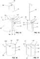
- the instillation line I can be provided with a liquid container 6, such as that in FIG Figure 14 is shown, be connected, in which an instillation fluid is stored.
- the liquid container 6, which can in particular be designed as a bag, can have a hanger 60 in order to hang it, for example, on an infusion stand with respect to the direction of gravity above or next to the peristaltic pump 3.
- a window 141 for a display and control panel is arranged in the area of the upper wall 14 of the pump unit housing 1.
- the device can be operated with the aid of the display and control panel, and in particular the function of the motor 20 can be set.
- the display and control panel can be used to display information on the status of the device, such as, in particular, current pump outputs and cycles, etc.
- the display and control panel can be designed as a touch screen, for example.
- FIG. 8 to 13 an embodiment is shown which differs only in the area of the peristaltic pump 3 from that of the embodiment of FIG Figures 1 to 7 distinguishes:
- the coupling between the coupling element 24 and the pump head 30 does not take place here eccentrically to the pump head 30 as in the embodiment of FIG Figures 1 to 7 , but central.
- the coupling takes place via a coupling element 331, which is freely rotatably mounted centrally in a recess 555 on the fluid collection container 5.
- the coupling element 331 is designed as an external square with an essentially square cross section.
- the coupling element 24 provided on the side of the pump unit housing is correspondingly complementary thereto as an internal square so that a rotary movement can be transmitted from the coupling element 24 to the coupling element 331.
- the coupling element 331 is attached non-rotatably and centrally to an internal gear 33.
- the inner wheel 33 forms a centrally arranged gear of a planetary gear 33, 34 and meshes with three decentrally arranged outer gears 34 which are also part of the planetary gear 33, 34.
- the external gears 34 in turn, mesh with the toothing 302 of the ring gear 301.
- the entire planetary gear 33, 34 and the ring gear 301 can be covered from the outside by means of a cover 32. Only the coupling element 331 protrudes outward through an opening arranged centrally in the cover 32.
- the outer wheels 34 form the pressure rollers for acting on the instillation line I in order to convey a substance contained therein to the wound area or to a body cavity.
- the embodiment shown of a device according to the invention is a peristaltic cassette 7 'as an intermediate part between a fluid collection container 5' and a pump unit housing I 'arranged.
- the peristaltic cassette 7 ' which thus forms a connection part, has a housing 71' with a hose guide for the instillation line I, which is passed through the housing 71 '.
- the peristaltic cassette 7 ' serves to connect a secretion line S and an auxiliary line H to the device.
- essentially all parts of the peristaltic cassette 7 ' are manufactured from a plastic by injection molding
- the peristaltic cassette 7 ' has an essentially cuboid, thin external shape.
- the fluid collection container 5 ', the peristaltic cassette 7' and the pump unit housing 1 ' together form an overall essentially cuboid shape with rounded outer edges and corners.
- the outer surfaces of the peristaltic cassette 7 ' are then each aligned with the correspondingly adjacent outer walls of the pump unit housing 1', i.e. with a front wall 10 ', a rear wall, a first side wall 12', a second side wall, an upper wall 14 'and a lower wall .
- the outer surfaces of the peristaltic cassette 7 ' are each arranged in alignment with the correspondingly adjoining outer walls of the fluid collection container 5', that is to say with a front wall 50 ', a rear wall, a first side wall 52', a second side wall 53 ', an upper wall 54' and a lower wall.
- the rear wall, the second side wall and the lower wall of the pump unit housing 1 'and the rear wall and the lower wall of the fluid collection container 5' cannot be seen in the figures.
- the peristaltic cassette 7 ' connects the pump unit housing 1' and the fluid collection container 5 'functionally by connecting a vacuum connection 17' on the housing side of the pump unit housing 1 'in an airtight manner to a vacuum connection 551' on the container side corresponding to the fluid collection container 5 '.
- the peristaltic cassette 7 ' has a vacuum connection 78' facing the fluid collection container 5 'and a vacuum connection 79' facing the pump unit housing 1 (see FIG Figure 15 or 18).
- the vacuum connections 78 'and 79' are in fluid communication with one another within the peristaltic cassette 7 '.
- the peristaltic cassette 7 ' also has an auxiliary connection 77' ( Figure 18 ) which, when the peristaltic cartridge 7 'is connected to the pump unit housing 1' as intended, is in fluid-tight connection with an auxiliary connection 181 'provided on the housing side on the pump unit housing 1'.
- the auxiliary connection 77 ' is within the housing 71' in fluid communication with an auxiliary line connection 74 'of the peristaltic cassette 7' ( Figure 15 ), which is used to connect an auxiliary line H.
- the auxiliary line H it is possible, if necessary, to flush the secretion line S and / or to measure the pressure in the secretion line S.
- the auxiliary line H preferably opens into the secretion line S in the vicinity of the cavity or wound.
- the peristaltic cassette 7' On its side facing the fluid collection container 5 ', the peristaltic cassette 7' has a secretion connection 76 'which is designed for coupling to a secretion connection 552' provided on the fluid collection container 5 'and inside the housing 71' in fluid communication with a secretion line connection 73 ' stands.
- the secretion line connection 73 ' is used to connect a secretion line S in order to suck body fluids through it via the secretion connections 76' and 552 'into the fluid collection container 5' and collect them therein.
- a vacuum is generated inside the fluid collecting container 5 'by means of a vacuum pump arranged in the pump unit housing 1' via the vacuum connections 17 ', 79', 78 'and 551'.
- the housing 71' On its side facing the pump unit housing 1 ', the housing 71' has the peristaltic cassette 7 ', as shown in FIG Figure 18 can be seen, a substantially circular recess 710 ', within which a pump head 30' of a peristaltic pump 3 'is freely rotatable.
- the pump head 30 ' has several pressure rollers 303', which serve to roll on the instillation line I laid around the pump head 30 'in the recess 710' and to supply a substance through the instillation line I to the wound area by means of mechanical deformation of the hose.
- the pump head 30 ' In order to transmit the rotary movement of a drive accommodated in the pump unit housing 1 'to the pump head 30', the pump head 30 'has a centrally arranged coupling element 331' in the form of a recess.
- the recess has a non-circular shape which is designed to be complementary to a coupling element 24 'arranged on the outside of the pump assembly housing 1'.
- the coupling element 24 ' is attached non-rotatably to a drive shaft which is designed to transfer a rotary movement brought about by the drive accommodated in the pump unit housing 1' to the coupling element 24 '.
- a suspension bracket 72 ' is attached to the peristaltic cassette 1' in order to suspend a liquid container 6 filled with instillation liquid by means of a hanger 60 with respect to the direction of gravity above the peristaltic cassette 1 '.
- the instillation line I leading out of the liquid container 6 is inserted through a first opening 75 'from above into the peristalsis cassette 7', within the recess 710 'around the pump head 30' around and through a second opening 75 'on the front of the peristaltic cassette 7' out of this again.
- FIG. 14 to 18 An operation in the Figures 14 to 18 The device shown is also possible without the peristaltic cassette 7 ', for example if only the suction of body fluids is necessary, but not the supply of a substance.
- the fluid collection container 5 ' is connected directly to the pump unit housing 1'.
- the coupling element 24 ' is then arranged in a recess 57' provided within the side wall 53 'of the fluid collecting container 5', so that any rotational movement of the coupling element 24 'remains ineffective.
- the vacuum connection 17 'on the housing side is coupled directly to the vacuum connection 551' on the container side.
- An adapter is inserted between the auxiliary connection 181 'on the housing side and the secretion connection 551' on the container side, which adapter has an auxiliary line connection connected to the auxiliary connection 181 'and a secretion line connection connected to the secretion connection 551'.
- FIG. 19 to 23 Another embodiment of the invention is shown in Figures 19 to 23 shown, in which not only a fluid collection container 5 ′′ can be fixed to a pump unit housing 1 ′′ and connected to it, but a further connection part in the form of an instillation container 4 ′′.
- the pump unit housing 1 ′′ is designed similarly to that of FIG Figure 1 and differs from this in particular in that the front wall 10 ′′ and the rear wall 11 ′′ project with their vertical wall edges not only to one side, but to both sides of the side wall arranged in between.
- the fluid collection container 5 ′′ is held between the wall edges of the front wall 10 ′′ and the rear wall 11 ′′ and on the other side the instillation container 4 ′′.
- An upper wall 14 ′′ of the pump unit housing 1 ′′ has a window 141 ′′ for a display and control panel for operating and for displaying the operating status of the device.
- the fluid collecting container 5 ′′ has a largely identical design with a base part 55 ′′ and a transparent part 56 ′′ as that of the one in FIG Figures 1 to 7 shown embodiment.
- the fluid collection container 5 is on by means of several pins 412"
- Pump unit housing 1 can be attached.
- no pump head is integrated in the fluid collection container 5 ′′.
- the secretion line S and the auxiliary line H are guided to the outside through the fluid collection container 5 ′′.
- the instillation container 4 ′′ which is advantageously manufactured largely entirely from a plastic in the injection molding process and is used to provide an instillation liquid, has a configuration similar to that of the fluid collection container 5 ′′. It has a transparent part 40 ′′ which is provided with a fill level scale 401 ′′, and a base part 41 ′′ made of an opaque material.
- annular recess 43 is formed, within which a ring gear 301" is arranged ( Figure 21 ).
- the ring gear 301 is freely rotatably attached to a bearing journal 410" provided concentrically within the annular recess 43 ".
- the bearing journal 410 ′′ has a recess 411 ′′ which is open in the radial direction towards the recess 43 ′′.
- the recess 43 "and the ring gear 301” ' are covered to the outside by means of a cover 32 ".
- An instillation line I which opens into the interior of the instillation container 4 "via an opening 42", is inserted into a hose guide formed deeply in the base part 41 ".
- the hose guide is guided by a feed channel extending from the opening 42" to the annular recess 43 ", of the annular recess 43 “and a channel leading upwards away from the recess 43".
- the installation line I is laid around the pump head 30" in such a way that when the pump head 30 "is rotated, the installation line I by means of the pressure rollers are mechanically deformed and the instillation liquid is thereby pumped out of the instillation container 4 ′′ and towards the wound area.
- a ventilation opening 44 is also provided on the base part 41" in order to let outside air into the instillation container 4 "when the amount of instillation liquid in the instillation container 4" becomes smaller during operation of the device.
- FIGS Figures 24 to 27 show an embodiment of a device not according to the invention, in which the pump head 30 ′ ′′ of a peristaltic pump 3 ′′ ′, in contrast to the ones in FIGS Figures 1 to 23 shown embodiments is not integrated in a connection part, but in the pump unit housing 1 '".
- a fluid collection container 5"' can be connected to the pump unit housing 1 '", which has a hose guide 559'" for guiding an instillation line I, so that the hose guide 559 '"The inserted hose in combination with the pump head 30 '" forms a peristaltic pump 3'".
- a motor 20 '"of a drive train 2'" is arranged in the interior 16 '"of the pump unit housing 1'", which is used to drive the pump head 30 '"which is fixedly attached to a motor shaft.
- a diaphragm pump is located in the interior 16'" 80 '"and a drive 81'" for driving this diaphragm pump 80 '".
- the drives 20'" and 81 '" are supplied with electrical energy by means of an accumulator 82'" also arranged in the interior 16 '".
- the membrane pump 80 '" is used to suck out body fluids by generating a vacuum in the fluid collection container 5'" via a vacuum connection 17 '"provided on the pump unit housing 1'" and connected to a vacuum connection 551 '"of the fluid collection container 5'” .
- the body fluids are thereby sucked through a secretion line S into the interior of the fluid collection container 5 '′′ and collected therein.
- the pump unit housing 1 '" has an upper wall 14'" with a window 141 '"for the arrangement of a display and control panel.
- a side wall 12'" lies flat on the fluid collection container 5 '"when it is connected to the pump unit housing 1'" as intended is.
- the pump unit housing 1 '" also has an auxiliary connection 181'" on the housing side, which, when the fluid collection container 5 '"is attached to the pump unit housing 1'", is coupled to an auxiliary connection 558 '"on the container side provided on the fluid collection container 5'", in order to be in fluid communication with an auxiliary line H.
- the auxiliary line H is used for flushing and / or measuring the pressure or the flow rate of the secretion line S.
- the pump head 30 ' on which a plurality of pressure rollers 303'" are also freely rotatably attached here, is arranged such that at least a region of its peripheral surface causes a mechanical deformation of the instillation line I during operation when it enters the Hose guide 559 '"of the fluid collection container 5'" is inserted and the fluid collection container 5 '"is properly connected to the pump unit housing 1'".
- the pump head 30 '" can be exposed with at least part of its circumferential surface, or, as is the case in the present embodiment, be covered there by a flexible cover membrane 121'" to prevent dirt particles from penetrating into the pump head 30 '"and to prevent the interior 16 '".
- the pump unit housing 1'" has a step through which the surface facing upward is penetrated by the pump head 30 '".
- the step enables the pump head 30'" with an area of its circumferential surface on the in The installation line I inserted into the hose guide 559 '"can act.
- the pump unit housing 1'" and the fluid collection container 5 "connected to it as intended have a substantially cuboid external shape. Due to the step, the front wall 10 '" and the rear wall, which are not visible in the figures of the pump unit housing 1 '"are each L-shaped.
- the fluid collection container 5 ' has a first side wall 52'" and a second side wall 53 '"facing the pump unit housing 1'", which from an upper protruding area 59 '", which also forms an upper wall 54'", in the direction of The front wall 50 '"and the rear wall, not visible in the figures, each have the shape of an upside-down L.
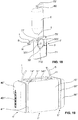
- FIG. 28 to 33 a further embodiment of a device not according to the invention is shown with a pump unit housing 1 "" and a connection part in the form of a fluid collecting container 5 "" that can be connected to it.
- the fluid collection container 5 "” has a cuboid external shape with a base part 55 “” and an advantageously transparent part 56 “".
- the base part 55 “” forms a cover which can be removed from the transparent part 56 “” and which faces the entire pump unit housing 1 "” Forms side surface of the fluid collection container 5 "”.
- the base part 55 ′′ ′′ is advantageously manufactured as a whole and essentially completely from a plastic in an injection molding process.
- the vacuum line leading from a vacuum pump housed in the pump unit housing 1 "" into the interior of the fluid collection container 5 “” extends via a housing-side vacuum connection 17 “” and a container-side vacuum connection 551 “” through the base part 55 “” when the fluid collection container 5 "” is properly connected to the pump unit housing 1 "".
- a secretion line S opens into the interior of the fluid collecting container 5 “” via the base part 55 "".
- an auxiliary line H leads into the pump unit housing 1 "" via an auxiliary connection 558 “” on the container side formed on the base part 55 “and via an auxiliary connection 181" “on the housing side when the fluid collecting container 5" “is connected to the pump unit housing 1" " If required, H is used to flush and / or measure the pressure of the secretion line S.
- the base part 55 ′′ ′′ has a recess on its side facing the pump assembly housing 1 ′′ ′′ through which the hose of an instillation line I traverses.
- the recess forms the hose bed and thus a hose guide 559 “" of a peristaltic pump 3 "" when the fluid collection container 5 "” is connected to the pump unit housing 1 "" as intended.
- the pump unit housing 1 "" shown is the pump head 30 "" of the peristaltic pump 3 "" of this device, which protrudes at least with part of its circumferential surface through a corresponding side wall of the pump unit housing 1 "" outwards to the fluid collection container 5 "".
- This protruding part of the pump head 30 "", of which in the Figure 29 only the pressure rollers 303 ′′ ′′ shown can, as in the present case, be covered by a flexible cover membrane 121 ′′ ′′.
- the instillation line I guided in the hose guide 559 “" opens via an orifice 42 "" into a flexible liquid bag 9 “” arranged in the interior 51 "" of the fluid collecting container 5 "".
- Instillation liquid is provided in the liquid bag 9 ′′ ′′, which can be supplied to the body through the instillation line I by means of the peristaltic pump 3 ′′ ′′.
- the Figure 32 it is shown that at the beginning of a treatment, as a rule, only the liquid bag 9 "” is filled. Over the duration of the treatment, the Fluid collection container 5 “” but increasingly with suctioned fluid, and the volume of the liquid bag 9 “” is reduced by the fluid supplied to the body.
- the drives accommodated can in particular each be a brushless direct current motor.
- An accumulator can be provided in the pump unit housing 1, 1 ', 1 ", 1'” or 1 "" in order to supply the drive with electrical power.
- the drive train between the drive and the pump head of the peristaltic pump can also have one or more gears in order to adapt the rotational speed of the pump head to that of the drive. It is also possible to arrange a freewheel in the drive train in order to only drive the pump head when the drive has a certain direction of rotation.
Landscapes
- Health & Medical Sciences (AREA)
- Heart & Thoracic Surgery (AREA)
- Engineering & Computer Science (AREA)
- Public Health (AREA)
- Veterinary Medicine (AREA)
- Biomedical Technology (AREA)
- Life Sciences & Earth Sciences (AREA)
- Animal Behavior & Ethology (AREA)
- General Health & Medical Sciences (AREA)
- Hematology (AREA)
- Anesthesiology (AREA)
- Vascular Medicine (AREA)
- Ophthalmology & Optometry (AREA)
- Pulmonology (AREA)
- Nuclear Medicine, Radiotherapy & Molecular Imaging (AREA)
- Surgery (AREA)
- Mechanical Engineering (AREA)
- General Engineering & Computer Science (AREA)
- Infusion, Injection, And Reservoir Apparatuses (AREA)
- External Artificial Organs (AREA)
- Reciprocating Pumps (AREA)
Claims (10)
- Dispositif pour aspirer des fluides corporels et pour amener une substance fluide à un corps humain ou animal, comprenantune unité d'entraînement (1, 1', 1"; 2) avec un entraînement (20) et avec une pompe à vide, laquelle sert à aspirer des fluides corporels,une tête de pompe (30, 30', 30") qui peut être entraînée par l'entraînement (20), ainsi que une pièce de connexion (5, 7', 4") qui peut être connectée de manière amovible à l'unité d'entraînement (1, 1', 1"; 2) avec un guide de tuyau (555, 710', 43"), lequel est conçu pour recevoir un tuyau (I) de telle sorte que le tuyau (I), lorsque la pièce de connexion (5, 7', 4") est connectée à l'unité d'entraînement (1, 1', 1"; 2) comme prévu, forme une pompe péristaltique (3, 3', 3") en combinaison avec la tête de pompe (30, 30', 30"), avec laquelle la substance fluide peut être transportée à travers le tuyau (I) vers le corps humain ou animal,caractérisé en ce quela tête de pompe (30, 30', 30") est intégrée dans la pièce de connexion (5, 7', 4") et que l'unité d'entraînement (1, 1', 1"; 2) présente un élément d'accouplement (24, 24') connecté à l'entraînement (20), lequel couple la tête de pompe (30, 30', 30") à l'entraînement (20) lorsque la pièce de connexion (5, 7', 4") est connectée à l'unité d'entraînement (1, 1', 1"; 2) comme prévu.
- Dispositif selon la revendication 1, dans lequel la pièce de connexion est un récipient de collecte de fluides (5) pour collecter les fluides corporels aspirés ou une partie d'un tel récipient de collecte de fluides ou une partie intermédiaire (7') qui peut être connectée à un tel récipient de collecte de fluides (5) pour établir une connexion entre l'unité d'entraînement (1, 1; 2) et le réservoir de collecte de fluides (5).
- Dispositif selon la revendication 1, dans lequel la pièce de connexion est un récipient d'instillation (4") qui sert à fournir la substance fluide.
- Dispositif selon l'une des revendications précédentes, dans lequel la pièce de connexion (5, 7', 4") possède une caractéristique d'identification et l'unité d'entraînement (1, 1', 1"; 2) possède une unité d'identification afin d'identifier quel type de pièce de connexion (5, 7', 4") est connecté à l'unité d'entraînement (1 , 1', 1"; 2), et dans lequel l'unité d'entraînement (1 , 1', 1"; 2) est conçue pour sélectionner un des modes de fonctionnement possibles parmi plusieurs modes de fonctionnement possibles en fonction du type de pièce de connexion (5, 7', 4") identifié pour entraîner la pompe péristaltique (3, 3', 3").
- Dispositif selon l'une des revendications précédentes, dans lequel la pièce de connexion (5, 7', 4") est une pièce jetable, qui est conçue pour une utilisation unique et notamment réalisée essentiellement entièrement à partir de pièces moulées par injection.
- Dispositif selon l'une des revendications précédentes, dans lequel la pièce de connexion (5, 7', 4") présente un engrenage (22; 33, 34), notamment un engrenage planétaire (33, 34), par lequel la tête de pompe (30, 30', 30") est couplée à l'entraînement (20), lorsque la pièce de connexion (5, 7', 4") est connectée à l'unité d'entraînement (1, 1"; 2) comme prévu.
- Dispositif selon l'une des revendications précédentes, dans lequel la tête de pompe (30, 30', 30") est couplée à l'entraînement (20) via au moins une roue libre (22), lorsque la pièce de connexion (5, 7', 4") est connectée à l'unité d'entraînement (1 , 1', 1"; 2) comme prévu.
- Dispositif selon l'une des revendications précédentes, dans lequel la pompe à vide est une pompe à membrane.
- Dispositif selon la revendication 8, dans lequel l'unité d'entraînement (1, 1', 1"; 2) présente un boîtier (1, 1', 1"), dans lequel à la fois l'entraînement (20) ainsi que la pompe à vide sont agencés.
- Dispositif selon la revendication 8 ou 9, dans lequel le même entraînement (20), qui sert à entraîner la pompe péristaltique (3, 3', 3"), sert également à entraîner la pompe à vide.
Priority Applications (1)
| Application Number | Priority Date | Filing Date | Title |
|---|---|---|---|
| EP19199460.7A EP3610899B1 (fr) | 2016-09-20 | 2017-09-18 | Dispositif d'aspiration et d'alimentation comprenant une unité d'entraînement et partie de raccordement |
Applications Claiming Priority (2)
| Application Number | Priority Date | Filing Date | Title |
|---|---|---|---|
| EP16189674 | 2016-09-20 | ||
| PCT/EP2017/073464 WO2018054833A2 (fr) | 2016-09-20 | 2017-09-18 | Dispositif d'aspiration et d'amenée comprenant une unité d'entraînement et une pièce de raccordement |
Related Child Applications (2)
| Application Number | Title | Priority Date | Filing Date |
|---|---|---|---|
| EP19199460.7A Division-Into EP3610899B1 (fr) | 2016-09-20 | 2017-09-18 | Dispositif d'aspiration et d'alimentation comprenant une unité d'entraînement et partie de raccordement |
| EP19199460.7A Division EP3610899B1 (fr) | 2016-09-20 | 2017-09-18 | Dispositif d'aspiration et d'alimentation comprenant une unité d'entraînement et partie de raccordement |
Publications (2)
| Publication Number | Publication Date |
|---|---|
| EP3515518A2 EP3515518A2 (fr) | 2019-07-31 |
| EP3515518B1 true EP3515518B1 (fr) | 2020-08-12 |
Family
ID=56997323
Family Applications (2)
| Application Number | Title | Priority Date | Filing Date |
|---|---|---|---|
| EP19199460.7A Active EP3610899B1 (fr) | 2016-09-20 | 2017-09-18 | Dispositif d'aspiration et d'alimentation comprenant une unité d'entraînement et partie de raccordement |
| EP17768457.8A Active EP3515518B1 (fr) | 2016-09-20 | 2017-09-18 | Dispositif d'aspiration et d'alimentation comprenant une unite d'entrainement et bloc de raccordement |
Family Applications Before (1)
| Application Number | Title | Priority Date | Filing Date |
|---|---|---|---|
| EP19199460.7A Active EP3610899B1 (fr) | 2016-09-20 | 2017-09-18 | Dispositif d'aspiration et d'alimentation comprenant une unité d'entraînement et partie de raccordement |
Country Status (6)
| Country | Link |
|---|---|
| US (2) | US11090417B2 (fr) |
| EP (2) | EP3610899B1 (fr) |
| CN (1) | CN109715229B (fr) |
| CA (1) | CA3035271A1 (fr) |
| ES (1) | ES2820243T3 (fr) |
| WO (1) | WO2018054833A2 (fr) |
Families Citing this family (9)
| Publication number | Priority date | Publication date | Assignee | Title |
|---|---|---|---|---|
| CN109646738A (zh) * | 2018-09-28 | 2019-04-19 | 德州飚丰信息技术有限公司 | 一种多功能临床引流控制装置 |
| AU2020405434A1 (en) * | 2019-12-17 | 2022-08-11 | Johnson & Johnson Surgical Vision, Inc. | Irrigation/aspiration pump head and bladder design and methods |
| WO2021178905A1 (fr) * | 2020-03-05 | 2021-09-10 | Deroyal Industries, Inc. | Système de raccordement de cartouche pour traitement de plaie par pression négative |
| EP3878486A1 (fr) | 2020-03-13 | 2021-09-15 | Medela Holding AG | Dispositif de traitement sous pression et d'instillation de plaies |
| EP3915605A1 (fr) | 2020-05-27 | 2021-12-01 | Medela Holding AG | Dispositif de transport pour un liquide corporel |
| US20240009376A1 (en) * | 2020-07-30 | 2024-01-11 | 3M Innovative Properties Company | Wound fluid collection canister with integrated irrigation fluid pump head |
| CN112089897B (zh) * | 2020-07-30 | 2023-09-15 | 京美德(深圳)医疗科技有限公司 | 一种介入式给药引流治疗装置 |
| US11957365B2 (en) | 2020-11-20 | 2024-04-16 | Covidien Lp | Aspiration pulsator |
| EP4309698A1 (fr) | 2022-07-22 | 2024-01-24 | Medela Holding AG | Pompe péristaltique à engrenage planétaire |
Family Cites Families (43)
| Publication number | Priority date | Publication date | Assignee | Title |
|---|---|---|---|---|
| US3646935A (en) * | 1969-08-21 | 1972-03-07 | Medical Dev Corp | Fluid collection systems |
| GB1457421A (en) * | 1973-01-04 | 1976-12-01 | Glaxo Lab Ltd | Cepham derivatives |
| US4634024A (en) | 1984-01-16 | 1987-01-06 | Technical Innovations, Inc. | Automatic resin dispensing apparatus |
| US4675010A (en) * | 1985-10-04 | 1987-06-23 | American Omni Medical, Inc. | Thoracic drainage collection system and method |
| US4798580A (en) | 1987-04-27 | 1989-01-17 | Site Microsurgical Systems, Inc. | Disposable peristaltic pump cassette system |
| FR2624378A1 (fr) | 1987-12-09 | 1989-06-16 | Mambrini Jean | Instillateur a microdebit |
| FR2624377A1 (fr) | 1987-12-09 | 1989-06-16 | Mambrini Jean | Instillateur a microdebit |
| FR2624376A1 (fr) | 1987-12-09 | 1989-06-16 | Mambrini Jean | Instillateur a microdebit jetable |
| US5183229A (en) * | 1991-12-12 | 1993-02-02 | Duggan Michael D | Baby bottle holder |
| US5324180A (en) * | 1992-09-04 | 1994-06-28 | Allergan, Inc. | Surgical instrument with drawer loading cassette system |
| GB2290718B (en) * | 1994-06-30 | 1998-07-01 | Cannon Rubber Ltd | Disposable baby bottle |
| US5496299A (en) * | 1994-09-21 | 1996-03-05 | C. R. Bard, Inc. | Suction reservoir |
| WO1998006446A2 (fr) * | 1996-08-15 | 1998-02-19 | Deka Products Limited Partnership | Pompe et systeme d'irrigation medicale |
| JP4021049B2 (ja) * | 1998-05-13 | 2007-12-12 | オリンパス株式会社 | 焼灼止血装置 |
| US20020177803A1 (en) * | 2001-05-23 | 2002-11-28 | Chappuis James L. | Combination drain and pain pump apparatus |
| US7527608B2 (en) * | 2002-08-12 | 2009-05-05 | Lma North America, Inc. | Medication infusion and aspiration system and method |
| US7625362B2 (en) | 2003-09-16 | 2009-12-01 | Boehringer Technologies, L.P. | Apparatus and method for suction-assisted wound healing |
| CA2515657C (fr) | 2003-02-11 | 2015-06-23 | Dilip Tapadiya, M.D., Inc. | Equipement d'irrigation de plaie |
| US7238010B2 (en) | 2003-04-14 | 2007-07-03 | Stryker Corporation | Surgical irrigation pump and tool system |
| PL1807145T3 (pl) | 2004-11-05 | 2016-06-30 | Convatec Technologies Inc | Próżniowy opatrunek na rany |
| US7438705B2 (en) * | 2005-07-14 | 2008-10-21 | Boehringer Technologies, L.P. | System for treating a wound with suction and method detecting loss of suction |
| CA2706824C (fr) * | 2006-05-09 | 2014-02-04 | Medela Holding Ag | Reservoir de collecteur de fluide |
| US20080154182A1 (en) | 2006-12-20 | 2008-06-26 | Robert Martin | Dual diameter arthroscopic irrigation/aspiration peristaltic pump system |
| US7510542B2 (en) | 2006-12-20 | 2009-03-31 | Linvatec Corporation | Dual pump irrigation/aspiration system and method for determining joint pressure |
| US20080154184A1 (en) | 2006-12-20 | 2008-06-26 | Blight David D | Arthroscopic irrigation/aspiration pump system with declogging feature |
| US8591453B2 (en) | 2006-12-20 | 2013-11-26 | Linvatec Corporation | Dual pump arthroscopic irrigation/aspiration system with outflow control |
| US20100174415A1 (en) * | 2007-04-20 | 2010-07-08 | Mark Humayun | Sterile surgical tray |
| DE102009038131A1 (de) | 2009-08-12 | 2011-02-17 | ATMOS Medizin Technik GmbH & Co. KG | Am Körper eines Benutzers tragbare Vorrichtung zur Bereitstellung von Unterdruck für medizinische Anwendungen |
| FR2960423B1 (fr) | 2010-05-27 | 2013-03-08 | Laurent Michel Marie Charroin | Dispositif d'administration de liquide charge ou non de substances a visee naso-sinusienne |
| JP6195826B2 (ja) * | 2011-05-27 | 2017-09-13 | ケーシーアイ ライセンシング インコーポレイテッド | 創傷治療ドレッシングに流体を供給するシステムおよび方法 |
| JP2015501170A (ja) | 2011-09-30 | 2015-01-15 | エクシジェント テクノロジーズ, エルエルシー | 界面動電ポンプ式の創傷治療システムおよび方法 |
| US9700457B2 (en) * | 2012-03-17 | 2017-07-11 | Abbott Medical Optics Inc. | Surgical cassette |
| CN202828507U (zh) * | 2012-08-23 | 2013-03-27 | 李智勇 | 可以同时装两种不同溶液的双嘴瓶 |
| GB201216928D0 (en) * | 2012-09-21 | 2012-11-07 | I2R Medical Ltd | Portable medical device system |
| KR102226847B1 (ko) | 2012-11-26 | 2021-03-15 | 케이씨아이 라이센싱 인코포레이티드 | 감압 치료 시스템용 복합 용액 펌프 및 저장 시스템 |
| DE102013226708A1 (de) | 2013-12-19 | 2015-06-25 | Paul Hartmann Ag | System zur kombinierten Unterdruck- und Instillationsbehandlung von Wunden |
| EP3960216A1 (fr) | 2014-07-18 | 2022-03-02 | 3M Innovative Properties Co. | Cartouche d'instillation et système de thérapie pour une thérapie par pression négative et une thérapie d'instillation |
| US20170304527A1 (en) | 2014-10-03 | 2017-10-26 | Mayo Foundation For Medical Education And Research | Wound irrigation system |
| CA2965503A1 (fr) | 2014-10-24 | 2016-04-28 | Kci Licensing, Inc. | Therapie a pression negative avec instillation a actionnement pneumatique |
| CN104771801A (zh) | 2015-01-26 | 2015-07-15 | 唐佩福 | 一种创面负压吸引冲洗仪器 |
| DE202015006341U1 (de) | 2015-09-08 | 2015-11-06 | Michael Eichler | Pumpenkassette |
| CN205515735U (zh) | 2015-12-25 | 2016-08-31 | 洪亚莲 | 一种妇科双腔式冲洗装置 |
| EP3603689B1 (fr) * | 2016-09-20 | 2023-07-19 | Medela Holding AG | Dispositif d'aspiration de fluides corporels et d'acheminement d'une substance |
-
2017
- 2017-09-18 CA CA3035271A patent/CA3035271A1/fr active Pending
- 2017-09-18 WO PCT/EP2017/073464 patent/WO2018054833A2/fr unknown
- 2017-09-18 CN CN201780058061.5A patent/CN109715229B/zh active Active
- 2017-09-18 ES ES17768457T patent/ES2820243T3/es active Active
- 2017-09-18 US US16/335,143 patent/US11090417B2/en active Active
- 2017-09-18 EP EP19199460.7A patent/EP3610899B1/fr active Active
- 2017-09-18 EP EP17768457.8A patent/EP3515518B1/fr active Active
-
2021
- 2021-07-14 US US17/375,880 patent/US20210338917A1/en active Pending
Non-Patent Citations (1)
| Title |
|---|
| None * |
Also Published As
| Publication number | Publication date |
|---|---|
| US11090417B2 (en) | 2021-08-17 |
| EP3515518A2 (fr) | 2019-07-31 |
| EP3610899B1 (fr) | 2023-11-01 |
| CN109715229B (zh) | 2023-01-03 |
| CA3035271A1 (fr) | 2018-03-29 |
| WO2018054833A3 (fr) | 2018-05-24 |
| US20210338917A1 (en) | 2021-11-04 |
| CN109715229A (zh) | 2019-05-03 |
| US20190275219A1 (en) | 2019-09-12 |
| WO2018054833A2 (fr) | 2018-03-29 |
| EP3610899A1 (fr) | 2020-02-19 |
| ES2820243T3 (es) | 2021-04-20 |
Similar Documents
| Publication | Publication Date | Title |
|---|---|---|
| EP3515518B1 (fr) | Dispositif d'aspiration et d'alimentation comprenant une unite d'entrainement et bloc de raccordement | |
| EP3603689B1 (fr) | Dispositif d'aspiration de fluides corporels et d'acheminement d'une substance | |
| EP1633414B2 (fr) | Pompe de perfusion modulaire | |
| EP2934615B1 (fr) | Unité téterelle pourvue d'une séparation de milieux | |
| WO2015172962A1 (fr) | Dispositif de dosage pour l'administration d'un fluide médicamenteux depuis un réservoir, comprenant une tige à broche destinée à la translation du piston | |
| WO2011035448A1 (fr) | Téterelle pour pomper du lait maternel humain | |
| WO2008141471A1 (fr) | Unité à pompe de drainage | |
| EP1448252A1 (fr) | Ensemble pompe medicale | |
| WO2011124388A1 (fr) | Dispositif d'aspiration pour aspirer un liquide corporel | |
| DE19725462A1 (de) | Medizinische Zahnradpumpe zum Saugen und Spülen | |
| EP3630264B1 (fr) | Module de pompe pour une pompe à perfusion technique médicale pourvu de différents états de fonctionnement | |
| WO2018172217A1 (fr) | Dispositif présentant une unité de pompe péristaltique pouvant être accouplée | |
| CN219308631U (zh) | 一种静脉配药中心用洁净室内自动配液装置 | |
| CN214811518U (zh) | 一种简易磨药装置 | |
| CN216148615U (zh) | 一种精神科临床用喂药装置 | |
| DE102009051443A1 (de) | Medizinische Zahnradpumpe | |
| EP3878486A1 (fr) | Dispositif de traitement sous pression et d'instillation de plaies | |
| DE202022100988U1 (de) | Dosiergerät für medizinische Lösungen | |
| DE202023002493U1 (de) | Lavage-System, insbesondere Pulse-Lavage-System | |
| CN113000171A (zh) | 一种简易磨药装置 |
Legal Events
| Date | Code | Title | Description |
|---|---|---|---|
| STAA | Information on the status of an ep patent application or granted ep patent |
Free format text: STATUS: UNKNOWN |
|
| STAA | Information on the status of an ep patent application or granted ep patent |
Free format text: STATUS: THE INTERNATIONAL PUBLICATION HAS BEEN MADE |
|
| PUAI | Public reference made under article 153(3) epc to a published international application that has entered the european phase |
Free format text: ORIGINAL CODE: 0009012 |
|
| STAA | Information on the status of an ep patent application or granted ep patent |
Free format text: STATUS: REQUEST FOR EXAMINATION WAS MADE |
|
| 17P | Request for examination filed |
Effective date: 20190301 |
|
| AK | Designated contracting states |
Kind code of ref document: A2 Designated state(s): AL AT BE BG CH CY CZ DE DK EE ES FI FR GB GR HR HU IE IS IT LI LT LU LV MC MK MT NL NO PL PT RO RS SE SI SK SM TR |
|
| AX | Request for extension of the european patent |
Extension state: BA ME |
|
| DAV | Request for validation of the european patent (deleted) | ||
| DAX | Request for extension of the european patent (deleted) | ||
| GRAP | Despatch of communication of intention to grant a patent |
Free format text: ORIGINAL CODE: EPIDOSNIGR1 |
|
| STAA | Information on the status of an ep patent application or granted ep patent |
Free format text: STATUS: GRANT OF PATENT IS INTENDED |
|
| INTG | Intention to grant announced |
Effective date: 20200304 |
|
| GRAS | Grant fee paid |
Free format text: ORIGINAL CODE: EPIDOSNIGR3 |
|
| GRAA | (expected) grant |
Free format text: ORIGINAL CODE: 0009210 |
|
| STAA | Information on the status of an ep patent application or granted ep patent |
Free format text: STATUS: THE PATENT HAS BEEN GRANTED |
|
| AK | Designated contracting states |
Kind code of ref document: B1 Designated state(s): AL AT BE BG CH CY CZ DE DK EE ES FI FR GB GR HR HU IE IS IT LI LT LU LV MC MK MT NL NO PL PT RO RS SE SI SK SM TR |
|
| REG | Reference to a national code |
Ref country code: CH Ref legal event code: EP |
|
| REG | Reference to a national code |
Ref country code: DE Ref legal event code: R096 Ref document number: 502017006744 Country of ref document: DE |
|
| REG | Reference to a national code |
Ref country code: IE Ref legal event code: FG4D Free format text: LANGUAGE OF EP DOCUMENT: GERMAN |
|
| REG | Reference to a national code |
Ref country code: AT Ref legal event code: REF Ref document number: 1300889 Country of ref document: AT Kind code of ref document: T Effective date: 20200915 Ref country code: CH Ref legal event code: NV Representative=s name: ISLER AND PEDRAZZINI AG, CH |
|
| REG | Reference to a national code |
Ref country code: SE Ref legal event code: TRGR |
|
| REG | Reference to a national code |
Ref country code: NL Ref legal event code: FP |
|
| REG | Reference to a national code |
Ref country code: LT Ref legal event code: MG4D |
|
| PG25 | Lapsed in a contracting state [announced via postgrant information from national office to epo] |
Ref country code: NO Free format text: LAPSE BECAUSE OF FAILURE TO SUBMIT A TRANSLATION OF THE DESCRIPTION OR TO PAY THE FEE WITHIN THE PRESCRIBED TIME-LIMIT Effective date: 20201112 Ref country code: GR Free format text: LAPSE BECAUSE OF FAILURE TO SUBMIT A TRANSLATION OF THE DESCRIPTION OR TO PAY THE FEE WITHIN THE PRESCRIBED TIME-LIMIT Effective date: 20201113 Ref country code: FI Free format text: LAPSE BECAUSE OF FAILURE TO SUBMIT A TRANSLATION OF THE DESCRIPTION OR TO PAY THE FEE WITHIN THE PRESCRIBED TIME-LIMIT Effective date: 20200812 Ref country code: LT Free format text: LAPSE BECAUSE OF FAILURE TO SUBMIT A TRANSLATION OF THE DESCRIPTION OR TO PAY THE FEE WITHIN THE PRESCRIBED TIME-LIMIT Effective date: 20200812 Ref country code: HR Free format text: LAPSE BECAUSE OF FAILURE TO SUBMIT A TRANSLATION OF THE DESCRIPTION OR TO PAY THE FEE WITHIN THE PRESCRIBED TIME-LIMIT Effective date: 20200812 Ref country code: BG Free format text: LAPSE BECAUSE OF FAILURE TO SUBMIT A TRANSLATION OF THE DESCRIPTION OR TO PAY THE FEE WITHIN THE PRESCRIBED TIME-LIMIT Effective date: 20201112 |
|
| PG25 | Lapsed in a contracting state [announced via postgrant information from national office to epo] |
Ref country code: PL Free format text: LAPSE BECAUSE OF FAILURE TO SUBMIT A TRANSLATION OF THE DESCRIPTION OR TO PAY THE FEE WITHIN THE PRESCRIBED TIME-LIMIT Effective date: 20200812 Ref country code: RS Free format text: LAPSE BECAUSE OF FAILURE TO SUBMIT A TRANSLATION OF THE DESCRIPTION OR TO PAY THE FEE WITHIN THE PRESCRIBED TIME-LIMIT Effective date: 20200812 Ref country code: LV Free format text: LAPSE BECAUSE OF FAILURE TO SUBMIT A TRANSLATION OF THE DESCRIPTION OR TO PAY THE FEE WITHIN THE PRESCRIBED TIME-LIMIT Effective date: 20200812 Ref country code: IS Free format text: LAPSE BECAUSE OF FAILURE TO SUBMIT A TRANSLATION OF THE DESCRIPTION OR TO PAY THE FEE WITHIN THE PRESCRIBED TIME-LIMIT Effective date: 20201212 |
|
| REG | Reference to a national code |
Ref country code: ES Ref legal event code: FG2A Ref document number: 2820243 Country of ref document: ES Kind code of ref document: T3 Effective date: 20210420 |
|
| PG25 | Lapsed in a contracting state [announced via postgrant information from national office to epo] |
Ref country code: RO Free format text: LAPSE BECAUSE OF FAILURE TO SUBMIT A TRANSLATION OF THE DESCRIPTION OR TO PAY THE FEE WITHIN THE PRESCRIBED TIME-LIMIT Effective date: 20200812 Ref country code: CZ Free format text: LAPSE BECAUSE OF FAILURE TO SUBMIT A TRANSLATION OF THE DESCRIPTION OR TO PAY THE FEE WITHIN THE PRESCRIBED TIME-LIMIT Effective date: 20200812 Ref country code: DK Free format text: LAPSE BECAUSE OF FAILURE TO SUBMIT A TRANSLATION OF THE DESCRIPTION OR TO PAY THE FEE WITHIN THE PRESCRIBED TIME-LIMIT Effective date: 20200812 Ref country code: EE Free format text: LAPSE BECAUSE OF FAILURE TO SUBMIT A TRANSLATION OF THE DESCRIPTION OR TO PAY THE FEE WITHIN THE PRESCRIBED TIME-LIMIT Effective date: 20200812 Ref country code: SM Free format text: LAPSE BECAUSE OF FAILURE TO SUBMIT A TRANSLATION OF THE DESCRIPTION OR TO PAY THE FEE WITHIN THE PRESCRIBED TIME-LIMIT Effective date: 20200812 |
|
| REG | Reference to a national code |
Ref country code: DE Ref legal event code: R097 Ref document number: 502017006744 Country of ref document: DE |
|
| PG25 | Lapsed in a contracting state [announced via postgrant information from national office to epo] |
Ref country code: AL Free format text: LAPSE BECAUSE OF FAILURE TO SUBMIT A TRANSLATION OF THE DESCRIPTION OR TO PAY THE FEE WITHIN THE PRESCRIBED TIME-LIMIT Effective date: 20200812 Ref country code: MC Free format text: LAPSE BECAUSE OF FAILURE TO SUBMIT A TRANSLATION OF THE DESCRIPTION OR TO PAY THE FEE WITHIN THE PRESCRIBED TIME-LIMIT Effective date: 20200812 |
|
| PLBE | No opposition filed within time limit |
Free format text: ORIGINAL CODE: 0009261 |
|
| STAA | Information on the status of an ep patent application or granted ep patent |
Free format text: STATUS: NO OPPOSITION FILED WITHIN TIME LIMIT |
|
| PG25 | Lapsed in a contracting state [announced via postgrant information from national office to epo] |
Ref country code: LU Free format text: LAPSE BECAUSE OF NON-PAYMENT OF DUE FEES Effective date: 20200918 Ref country code: SK Free format text: LAPSE BECAUSE OF FAILURE TO SUBMIT A TRANSLATION OF THE DESCRIPTION OR TO PAY THE FEE WITHIN THE PRESCRIBED TIME-LIMIT Effective date: 20200812 |
|
| 26N | No opposition filed |
Effective date: 20210514 |
|
| PG25 | Lapsed in a contracting state [announced via postgrant information from national office to epo] |
Ref country code: SI Free format text: LAPSE BECAUSE OF FAILURE TO SUBMIT A TRANSLATION OF THE DESCRIPTION OR TO PAY THE FEE WITHIN THE PRESCRIBED TIME-LIMIT Effective date: 20200812 Ref country code: IE Free format text: LAPSE BECAUSE OF NON-PAYMENT OF DUE FEES Effective date: 20200918 |
|
| PG25 | Lapsed in a contracting state [announced via postgrant information from national office to epo] |
Ref country code: TR Free format text: LAPSE BECAUSE OF FAILURE TO SUBMIT A TRANSLATION OF THE DESCRIPTION OR TO PAY THE FEE WITHIN THE PRESCRIBED TIME-LIMIT Effective date: 20200812 Ref country code: MT Free format text: LAPSE BECAUSE OF FAILURE TO SUBMIT A TRANSLATION OF THE DESCRIPTION OR TO PAY THE FEE WITHIN THE PRESCRIBED TIME-LIMIT Effective date: 20200812 Ref country code: CY Free format text: LAPSE BECAUSE OF FAILURE TO SUBMIT A TRANSLATION OF THE DESCRIPTION OR TO PAY THE FEE WITHIN THE PRESCRIBED TIME-LIMIT Effective date: 20200812 |
|
| PG25 | Lapsed in a contracting state [announced via postgrant information from national office to epo] |
Ref country code: MK Free format text: LAPSE BECAUSE OF FAILURE TO SUBMIT A TRANSLATION OF THE DESCRIPTION OR TO PAY THE FEE WITHIN THE PRESCRIBED TIME-LIMIT Effective date: 20200812 |
|
| PG25 | Lapsed in a contracting state [announced via postgrant information from national office to epo] |
Ref country code: PT Free format text: LAPSE BECAUSE OF FAILURE TO SUBMIT A TRANSLATION OF THE DESCRIPTION OR TO PAY THE FEE WITHIN THE PRESCRIBED TIME-LIMIT Effective date: 20200812 |
|
| P01 | Opt-out of the competence of the unified patent court (upc) registered |
Effective date: 20230524 |
|
| PGFP | Annual fee paid to national office [announced via postgrant information from national office to epo] |
Ref country code: NL Payment date: 20230920 Year of fee payment: 7 Ref country code: IT Payment date: 20230921 Year of fee payment: 7 Ref country code: GB Payment date: 20230920 Year of fee payment: 7 |
|
| REG | Reference to a national code |
Ref country code: AT Ref legal event code: MM01 Ref document number: 1300889 Country of ref document: AT Kind code of ref document: T Effective date: 20220918 |
|
| PGFP | Annual fee paid to national office [announced via postgrant information from national office to epo] |
Ref country code: SE Payment date: 20230920 Year of fee payment: 7 Ref country code: FR Payment date: 20230928 Year of fee payment: 7 Ref country code: DE Payment date: 20230920 Year of fee payment: 7 Ref country code: BE Payment date: 20230920 Year of fee payment: 7 |
|
| PGFP | Annual fee paid to national office [announced via postgrant information from national office to epo] |
Ref country code: ES Payment date: 20231124 Year of fee payment: 7 |
|
| PG25 | Lapsed in a contracting state [announced via postgrant information from national office to epo] |
Ref country code: AT Free format text: LAPSE BECAUSE OF NON-PAYMENT OF DUE FEES Effective date: 20220918 |
|
| PGFP | Annual fee paid to national office [announced via postgrant information from national office to epo] |
Ref country code: CH Payment date: 20231001 Year of fee payment: 7 |