EP3515331B1 - Kit zur herstellung von löchern in kontrollierter tiefe und mit verschiedenen durchmessern auf chondralen und osteochondralen oberflächen - Google Patents
Kit zur herstellung von löchern in kontrollierter tiefe und mit verschiedenen durchmessern auf chondralen und osteochondralen oberflächen Download PDFInfo
- Publication number
- EP3515331B1 EP3515331B1 EP17780524.9A EP17780524A EP3515331B1 EP 3515331 B1 EP3515331 B1 EP 3515331B1 EP 17780524 A EP17780524 A EP 17780524A EP 3515331 B1 EP3515331 B1 EP 3515331B1
- Authority
- EP
- European Patent Office
- Prior art keywords
- chondral
- osteochondral
- hole
- pin
- defining
- Prior art date
- Legal status (The legal status is an assumption and is not a legal conclusion. Google has not performed a legal analysis and makes no representation as to the accuracy of the status listed.)
- Active
Links
Images



Classifications
-
- A—HUMAN NECESSITIES
- A61—MEDICAL OR VETERINARY SCIENCE; HYGIENE
- A61B—DIAGNOSIS; SURGERY; IDENTIFICATION
- A61B17/00—Surgical instruments, devices or methods
- A61B17/16—Instruments for performing osteoclasis; Drills or chisels for bones; Trepans
- A61B17/1637—Hollow drills or saws producing a curved cut, e.g. cylindrical
-
- A—HUMAN NECESSITIES
- A61—MEDICAL OR VETERINARY SCIENCE; HYGIENE
- A61B—DIAGNOSIS; SURGERY; IDENTIFICATION
- A61B17/00—Surgical instruments, devices or methods
- A61B17/16—Instruments for performing osteoclasis; Drills or chisels for bones; Trepans
- A61B17/1613—Component parts
- A61B17/1626—Control means; Display units
-
- A—HUMAN NECESSITIES
- A61—MEDICAL OR VETERINARY SCIENCE; HYGIENE
- A61B—DIAGNOSIS; SURGERY; IDENTIFICATION
- A61B17/00—Surgical instruments, devices or methods
- A61B17/16—Instruments for performing osteoclasis; Drills or chisels for bones; Trepans
- A61B17/1613—Component parts
- A61B17/1633—Sleeves, i.e. non-rotating parts surrounding the bit shaft, e.g. the sleeve forming a single unit with the bit shaft
-
- A—HUMAN NECESSITIES
- A61—MEDICAL OR VETERINARY SCIENCE; HYGIENE
- A61B—DIAGNOSIS; SURGERY; IDENTIFICATION
- A61B17/00—Surgical instruments, devices or methods
- A61B17/16—Instruments for performing osteoclasis; Drills or chisels for bones; Trepans
- A61B17/1659—Surgical rasps, files, planes, or scrapers
-
- A—HUMAN NECESSITIES
- A61—MEDICAL OR VETERINARY SCIENCE; HYGIENE
- A61B—DIAGNOSIS; SURGERY; IDENTIFICATION
- A61B90/00—Instruments, implements or accessories specially adapted for surgery or diagnosis and not covered by any of the groups A61B1/00 - A61B50/00, e.g. for luxation treatment or for protecting wound edges
- A61B90/03—Automatic limiting or abutting means, e.g. for safety
-
- A—HUMAN NECESSITIES
- A61—MEDICAL OR VETERINARY SCIENCE; HYGIENE
- A61B—DIAGNOSIS; SURGERY; IDENTIFICATION
- A61B17/00—Surgical instruments, devices or methods
- A61B17/16—Instruments for performing osteoclasis; Drills or chisels for bones; Trepans
- A61B17/1613—Component parts
- A61B17/162—Chucks or tool parts which are to be held in a chuck
-
- A—HUMAN NECESSITIES
- A61—MEDICAL OR VETERINARY SCIENCE; HYGIENE
- A61B—DIAGNOSIS; SURGERY; IDENTIFICATION
- A61B17/00—Surgical instruments, devices or methods
- A61B17/16—Instruments for performing osteoclasis; Drills or chisels for bones; Trepans
- A61B17/1635—Instruments for performing osteoclasis; Drills or chisels for bones; Trepans for grafts, harvesting or transplants
-
- A—HUMAN NECESSITIES
- A61—MEDICAL OR VETERINARY SCIENCE; HYGIENE
- A61B—DIAGNOSIS; SURGERY; IDENTIFICATION
- A61B17/00—Surgical instruments, devices or methods
- A61B17/16—Instruments for performing osteoclasis; Drills or chisels for bones; Trepans
- A61B17/1662—Instruments for performing osteoclasis; Drills or chisels for bones; Trepans for particular parts of the body
- A61B17/1675—Instruments for performing osteoclasis; Drills or chisels for bones; Trepans for particular parts of the body for the knee
-
- A—HUMAN NECESSITIES
- A61—MEDICAL OR VETERINARY SCIENCE; HYGIENE
- A61B—DIAGNOSIS; SURGERY; IDENTIFICATION
- A61B17/00—Surgical instruments, devices or methods
- A61B17/16—Instruments for performing osteoclasis; Drills or chisels for bones; Trepans
- A61B17/1697—Instruments for performing osteoclasis; Drills or chisels for bones; Trepans specially adapted for wire insertion
-
- A—HUMAN NECESSITIES
- A61—MEDICAL OR VETERINARY SCIENCE; HYGIENE
- A61B—DIAGNOSIS; SURGERY; IDENTIFICATION
- A61B17/00—Surgical instruments, devices or methods
- A61B17/16—Instruments for performing osteoclasis; Drills or chisels for bones; Trepans
- A61B17/17—Guides or aligning means for drills, mills, pins or wires
- A61B17/1739—Guides or aligning means for drills, mills, pins or wires specially adapted for particular parts of the body
- A61B17/1764—Guides or aligning means for drills, mills, pins or wires specially adapted for particular parts of the body for the knee
-
- A—HUMAN NECESSITIES
- A61—MEDICAL OR VETERINARY SCIENCE; HYGIENE
- A61B—DIAGNOSIS; SURGERY; IDENTIFICATION
- A61B17/00—Surgical instruments, devices or methods
- A61B2017/0046—Surgical instruments, devices or methods with a releasable handle; with handle and operating part separable
-
- A—HUMAN NECESSITIES
- A61—MEDICAL OR VETERINARY SCIENCE; HYGIENE
- A61B—DIAGNOSIS; SURGERY; IDENTIFICATION
- A61B17/00—Surgical instruments, devices or methods
- A61B17/16—Instruments for performing osteoclasis; Drills or chisels for bones; Trepans
- A61B2017/1602—Mills
-
- A—HUMAN NECESSITIES
- A61—MEDICAL OR VETERINARY SCIENCE; HYGIENE
- A61B—DIAGNOSIS; SURGERY; IDENTIFICATION
- A61B90/00—Instruments, implements or accessories specially adapted for surgery or diagnosis and not covered by any of the groups A61B1/00 - A61B50/00, e.g. for luxation treatment or for protecting wound edges
- A61B90/03—Automatic limiting or abutting means, e.g. for safety
- A61B2090/033—Abutting means, stops, e.g. abutting on tissue or skin
- A61B2090/034—Abutting means, stops, e.g. abutting on tissue or skin abutting on parts of the device itself
Definitions
- the present invention relates to a kit for making holes at controlled depth and of different diameters on chondral and osteochondral surfaces.
- the present invention relates to an apparatus able to make holes for cartilaginous and osteocartilaginous substitutes for the regeneration of chondral and osteochondral tissues such as, for example, the cartilaginous and osteocartilaginous substitutes described in patent application no. WO2006092718 by the same Applicant.
- the present invention further relates to a kit for preparing the damaged chondral or osteochondral area for the creation of the mentioned hole.
- chondral and osteochondral substitutes for the regeneration of the chondral and osteochondral tissues are applied for the treatment of lesions characterised by areas lacking (totally or partially) cartilaginous or osteocartilaginous tissue, or for the neo-formation of cartilaginous tissue and/or sub-chondral bone tissue.
- Such chondral or osteochondral lesions can present in different forms, sizes and depths, according to the pathology or the cause of the damage, therefore surgical techniques vary according to these parameters and the substitute to be applied.
- cartilaginous and osteocartilaginous substitutes Before proceeding with the implant of the cartilaginous and osteocartilaginous substitutes, it is appropriate to expose the area of the lesion through an arthrotomic or mini-arthrotomic incision, in order to remove the damaged tissue.
- a suitable housing for the implant of cartilaginous or osteocartilaginous substitute for example, with side walls perpendicular to the bottom of the lesion itself and with a flat bottom.
- the lesion should be, therefore, appropriately shaped and prepared, defining a suitable housing site.
- a hole is prepared in correspondence of the lesion with a predetermined shape, width and depth, both based on the size of the lesion and according to the size of the respective chondral or osteochondral substitute to implant.
- manually activated equipment such as, for example, reamer members adapted to enlarge the lesion to a determined size.
- Such equipment comprises a cutting head adapted to remove chondral or osteochondral tissue from the area surrounding the lesion and thus to define the hole.
- the cutting head has an edge which, running along the surface, scrapes the surface itself removing surface tissue from it. The movement of the edge is performed manually by an operator who, by acting on a respective gripping member, compresses the head onto the surface and simultaneously rotates the head in order to remove the chondral or osteochondral tissue.
- the head is supported by a containment body which is withheld manually during the compression and rotation action, to correctly position the head at the area to be bored.
- the size of the hole is, therefore, determined by the size of the cutting head and edge. Therefore, according to the desired width, the apparatus with a suitably sized head is chosen.
- the depth of the hole is adjusted by the compression action of the user pushing the head in a perpendicular direction to the planar extension of the surface.
- control of the depth of the hole is performed manually by the operator who sees to stopping the scraping action once the determined depth has been reached.
- optical measurement systems are envisaged, generally arranged on the containment body and comprising numerical references visible to the operator during their tissue removal action.
- numerical references cannot be displayed during the boring action. In this situation, the operator must periodically stop the compression and rotation actions of the head to check the depth reached through the mentioned numerical references.
- equipment is provided with a determined axial sliding of the cutting head with respect to the containment body.
- the stroke of the head determines the depth to be reached in the material removal operations.
- the apparatus is subject to periodic maintenance operations that substantially affect the management costs of the apparatus, given the need to operate on a multitude of tools.
- a further significant drawback of the known apparatus summarised above is determined by the difficulty for the operator to orient the head with respect to the chondral or osteochondral surface to be removed.
- the action of positioning and withholding the containment body with respect to the chondral and osteochondral surface is performed manually. Consequently, during the rotation of the head it is difficult to keep the edge with the respective advancement direction perpendicular to the planar extension of the chondral or osteochondral surface.
- the main technical task of the present invention is to provide an apparatus and a kit for making holes on chondral and osteochondral surfaces that is able to overcome the drawbacks described above.
- the apparatus and the kit according to the present invention have the aim of facilitating the implant of cartilaginous and osteocartilaginous substitutes through mini-arthrotomic or arthrotomic surgery for the treatment of medium/small defects. This guarantees a less invasive, faster, more linear surgical approach and with lower margins of error, as well as a better reproducibility and precision in surgeries. It is also considered that this could minimise the onset of adverse events that can arise following a more invasive surgical approach.
- the instruments according to the present invention will also be able to create holes of controlled depths and different diameters for the treatment of chondral and osteochondral lesions.
- the apparatus is able to make holes for the housing of cartilaginous and osteocartilaginous substitutes such as, for example, those described and illustrated in patent application WO2006092718 by the Applicant.
- an important object of the invention is to propose a single apparatus able to make a hole of any depth.
- a further object of the present invention is to provide an apparatus able to effectively make a hole on chondral and osteochondral surfaces, and at the same time structurally simple and easy to use.
- a further object of the present invention is to provide a kit that can prepare the chondral or osteochondral surface in order to correctly create the hole.
- the set technical task and the specified aims are substantially attained by an apparatus and a kit for making holes on chondral or osteochondral surfaces in accordance with one or more of the accompanying claims.
- Apparatus 1 is comprised within a kit 100 illustrated overall in figure 1 , provided to prepare and make the mentioned hole on surface "A".
- apparatus 1 comprises a reamer member 2 having at least one cutting head 3 for removing tissue from the chondral or osteochondral surface "A" schematically illustrated solely by way of example in the form of a solid having a substantially oval conformation.
- the reamer member 2 is mobile approaching the chondral or osteochondral surface, along an axis of longitudinal extension "X" for arranging the head 3 at the mentioned tissue.
- the apparatus 1 further comprises guide means 4 of the reamer member 2 that can be firmly associated with the chondral or osteochondral surface A.
- the guide means 4 are associated with the surface "A" to provide a stable reference for the head 3 during the respective removal operations of the chondral or osteochondral tissue.
- the reamer member 2 may be slidable along the mentioned guide means 4 and along the mentioned longitudinal axis "X".
- the apparatus 1 further comprises mechanical control means 5 for controlling the depth of the hole interposed between the reamer member 2 and the guide means 4.
- the mechanical means 5 define a mechanical end stop of the reamer member 2 during the respective movement towards the chondral or osteochondral surface "A" and along the longitudinal axis "X".
- the depth of the hole which depends on the movement of the reamer member 2 towards the surface "A" and along the axis "X", is determined mechanically by the mentioned means 5 which prevent, as will be better clarified below, the excessive sliding in depth of the head 3 on the chondral or osteochondral surface "A".
- the guide means 4 are constituted by at least one pin 6 having a rod-shaped conformation and partly insertable within the chondral or osteochondral surface "A".
- the pin 6 has an end tip 6a configured to penetrate into the surface "A” anchoring the pin 6 itself to the bone. In this situation, the pin 6 defines a free end 6b projecting from the surface "A" ( figure 2a ).
- the pin 6 is inserted at an area of the surface "A" in which there is a lesion to be treated through the application of a cartilaginous or osteocartilaginous substitute.
- the free end 6b of the pin 6 is inserted into the reamer member 2 to allow the sliding of the member 2 itself along the extension of the pin 6 corresponding to the mentioned longitudinal axis "X".
- the reamer member 2 comprises a tubular element 7 having a hole 8 for housing the free end 6b of the pin 6.
- the tubular element 7 has a circular cross section and defines a first end 7a on which the mentioned cutting head 3 is associated and equipped with the access opening to the hole 8 ( figure 1 ).
- the cutting head 3 comprises at least two edges 9 adapted to scrape the surface tissue to define the reaming action of the lesion.
- the cutting head 3 has four edges 9 in a "cross" arrangement, i.e. arranged on two perpendicular lines.
- the edges 9 have an appropriately sized conformation according to the width of the hole to be obtained.
- each edge 9 is afforded in a respective portion 9a projecting from the first end 7a of the tubular element 7.
- the portions 9a are reciprocally near and equally spaced so as to arrange the respective edges 9 at 90° from one another and with respect to the circumferential extension of the tubular element 7.
- edges 9 may be equipped with relevant toothing promoting the scraping and removal action of the tissue.
- toothing is provided for large cutting heads 3.
- other outlines may be provided for appropriately preparing the head 3 for making holes on any type of surface, such as the bone surface.
- the tubular element 7 further has a second end 7b opposite the first 7a and equipped with a gripping member 10 adapted to be held by the operator to transmit the rotation of the tubular element 7 (and therefore of the cutting head 3) about the axis "X" and simultaneously to press the head 3 against the surface "A".
- the gripping member 10 is removably associable with the tubular element 7 to be disengaged therefrom at the end of the reaming action.
- the gripping member 10 has a first portion 11 defining an ergonomic handle, and a second portion 12 opposite the first 11, having a bushing 13 with a cylindrical conformation.
- the bushing 13 internally has a seat 14 ( figure 1 ) for the jointing of the second end 7b of the tubular element 7.
- the seat 14 of the bushing has a square section conformation, for housing an end portion 15 of the second end 7b of the element 7, countershaped to the seat 14.
- the terminal portion 15 has a square shaped cross section.
- the terminal portion 15 is inserted into the seat 14 and engaged by mechanical jointing, in order to define the coupling of the gripping member 10 with the reamer member 2.
- the apparatus 1 further comprises a support body 16 having a circular section tubular conformation for containing the reamer member 2.
- the tubular element 7 has a first portion proximal to the first end 7a contained in the body 16, and a second portion 18 proximal to the second end 7b and projecting out of the support body 16.
- the body 16 has a first circular end edge 19 provided to be positioned on the chondral or osteochondral surface "A".
- the body 16 may have an edge 19 made by arched semi-parts spaced out from one another and extending along the same circular path. Through windows 21 are further afforded at the edge 19 on the body 16, adapted to allow the visual control of the head 3 during the chondral or osteochondral tissue removal action.
- a second end edge 20 extends at the second portion 18 of the element 7.
- the internal cavity of the body 16 has a cross section with dimensions such as to allow the containment and sliding of the tubular element 7.
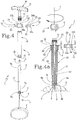
- the mechanical means 5 for controlling the depth of the hole comprise at least one cylindrical insert 22 which can be fitted into the second portion 18 of the tubular element 7 so as to separate the bushing 13 of the gripping member 10 from the second end edge 20 of the support body 16.
- the cylindrical insert 22 has a cup-shaped conformation defining a lateral wall 23 having a substantially annular profile, and a central wall 24 having a circular profile.
- the central wall 24 has a through hole 25 for inserting the second portion 18 of the tubular element 7. Furthermore, the central wall 24 has a thickness "S" ( figure 4a ) defining the depth of the hole afforded on the chondral or osteochondral surface "A".
- the central wall 24 spaces out the bushing 13 from the body 16 preventing the bushing 13 from coming into contact with the second edge 20 during the reaming action.
- the central wall 24 has an internal face 24a facing towards the support body 16 and that can be fitted onto the second end edge 20, and an external face 24b facing the bushing 13 and that can be fitted onto a flat surface 14a of the bushing 13 itself on which the mentioned jointing seat 14 is afforded.
- the thickness value "S" (distance between the internal face 24a and the external one 24b) of the central wall 24 is inversely proportional to the depth of the hole.
- the lateral wall 23 extends around the second end edge 20 of the support body 16.
- the lateral wall 23 further has an external surface 23a showing the alphabetical/numerical/alpha-numerical references or other symbols and icons indicative of the depth of the hole to be made on the chondral or osteochondral surface "A" (and therefore the thickness value "S" of the central wall 24).
- cylindrical insert 22 is removably associated with the second portion 18 of the tubular element 7 to be substituted with an insert 22 having a different thickness "S" and therefore able to provide a suitable mechanical end stroke for reaching the predetermined depth of the hole.
- the insert 22 is fitted onto the second portion 18 of the tubular element 7 until the internal face 24a is in abutment on the second end edge 20. Subsequently, the gripping member 10 is coupled to the tubular element 7 through the insertion of the terminal portion 15 into the seat 14.
- the presence of the insert 22 ensures the correct depth that the head 3 must reach in the operations for removing chondral or osteochondral tissue.
- the present invention further relates to a kit 100 for making holes, which comprises the mentioned apparatus 1.
- the kit 100 has an element 28 for applying the pin 6, comprising a body 29 equipped with a through cavity 30 for inserting the pin 6.
- the element 28 for applying the pin 6 has a flat end portion 31 of the body 29, equipped with an access hole to the through cavity 30 ( figure 1 ).
- the flat portion 31 has a contact surface 32 with the chondral and osteochondral surface "A" lying on an extension plane perpendicular to the longitudinal extension axis of the body 29.
- the orientation of the contact surface 32 with respect to the body 29 and the respective through cavity 30 allows the pin 6 to be arranged with the respective longitudinal axis perpendicular to the lying plane of the chondral or osteochondral surface "A".
- the element 28 for applying the pin 6 rests on the surface "A” with the respective contact surface 32 fitted onto the lesion to be treated (not shown in the appended figures).
- the pin 6 is inserted into the through cavity 30 making the end 6a penetrate into the surface "A" ( figure 2a ). It is to be noted that the body 29 of the element 28 for applying the pin 6 has the same length of the free end 6b of the pin 6 inserted into the chondral or osteochondral surface "A".
- the optimal depth of insertion of the pin 6 is determined by inserting the pin 6 into the surface "A" until the respective free end 6b is fully contained within the cavity 30.
- the body 29 is extracted leaving the pin 6 projecting from the area of the surface "A" for boring.
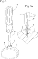
- the kit 100 further comprises an incision member 33, having at least one cutting tool 34 for making an incision on the chondral or osteochondral reference surface "A" for positioning the head 3.
- the cutting tool 34 comprises a circular blade 35 for defining an incision with a circular profile.
- the tool 34 is coupled to the end of a hollow body 36, having a substantially tubular conformation with a circular section.
- the hollow body 36 has an internal hole 37 having access to the centre of the blade 35 and adapted to house the mentioned free end 6b of the pin 6.
- the hollow body 2 is engaged with a gripping portion 38 that has an ergonomic handle, such as to allow the easy rotation of the tool 34 on the chondral or osteochondral surface.
- the gripping portion 38 which extends from the opposite side to the cutting tool 34, preferably has a substantially cylindrical conformation to be held by the operator and easily moved.
- the cutting tool 34 may be chosen with a respective diameter according to the hole to be made.
- the hollow body 36 is fitted onto the free end 6b of the pin 6 inserted into the chondral and osteochondral surface "A".
- the operator can, therefore, incise the surface "A” pressing the circular blade 35 onto the surface "A” and simultaneously rotating the tool 34 to ease the incision ( figure 3 and 3a ).
- the gripping member 10 is coupled to the terminal portion 15 of the tubular element 7.
- the kit 100 comprises a plurality of cylindrical inserts 22 having different thicknesses "S" and therefore defining different depths of the hole. It is also to be noted that, as can be seen more clearly in figure 1 and in figure 4 , the larger the thickness "S" of the central wall 24 of the insert 22 is (and therefore the lower the depth of the hole), the lower the longitudinal section width of the lateral wall 23 is.
- figure 1 illustrates three inserts 22 respectively defining a depth of the hole equal to 2 mm, a depth of the hole equal to 4 mm and one equal to 6 mm.
- the lateral wall 23 of the insert defining the 6mm hole is wider than the lateral wall 23 of the insert defining the 4 mm hole.
- the lateral wall 23 of the insert defining the 4mm hole is wider than the lateral wall 23 of the insert which defines the depth of 2 mm.
- the operator chooses the right insert 22 for the depth to be obtained, either by reading the alphabetical/numerical/alpha-numerical or ornamental references marked on the lateral wall 23 (as for example in figure 1 ) or by comparing the width of the wall 23 with the thickness of the chondral or osteochondral substitute to be implanted.
- insert 22 is made very simply and immediately, even simply by direct comparison between the chondral or osteochondral substitute and the lateral wall 23 of the insert 22.
- tubular element 7 is fitted onto the pin 6 by inserting the free end 6b into the hole 8 and making the first end edge 19 coincide with the circular incision previously made by the incision member 33.
- the head 3 is rotated and pressed onto the surface "A" for removing the chondral or osteochondral material with the consequent definition of the hole.
- the insert 22 determines a mechanical end stop which defines the depth of the hole. Therefore, when the bushing 13 is brought into contact with the insert 22, the reaming operation is stopped and the apparatus 1 is removed from the pin 6.
- the element 28 guided by the pin 6 into the hole A is further used in order to measure the depth of the hole.
- alphabetical/numerical/alphanumerical indicators or graphical representations are marked, preferably engraved on visible surfaces of the portion 31.
- the present invention presents numerous advantages and reaches the objects set.
- the apparatus 1 is able to create holes of any depth, making use of a mechanical control determined by the inserts 22 with differentiated sizes.
- the apparatus 1 is very cost-efficient since only the insert 22 is substituted, suitable for the depth of the hole to be made, but maintaining all the mechanical members for making the hole.
- a further advantage of the present invention is provided by the structural and operating simplicity of the apparatus 1 able to effectively make a hole by making use of both a mechanical and optical depth control system.
- the kit 100 allows the surface "A" to be prepared in order to make the hole correctly. This advantage is given by the pin 6 and by the respective insertion system which guarantees the perpendicularity of the pin 6 with respect to the surface "A". Consequently, the pin determines a guide and positioning member of the apparatus 1 for the correct direction of the cutting head 3 during the reaming step.
Landscapes
- Health & Medical Sciences (AREA)
- Surgery (AREA)
- Life Sciences & Earth Sciences (AREA)
- Animal Behavior & Ethology (AREA)
- Public Health (AREA)
- Veterinary Medicine (AREA)
- Oral & Maxillofacial Surgery (AREA)
- Engineering & Computer Science (AREA)
- Biomedical Technology (AREA)
- Heart & Thoracic Surgery (AREA)
- Medical Informatics (AREA)
- Molecular Biology (AREA)
- Nuclear Medicine, Radiotherapy & Molecular Imaging (AREA)
- General Health & Medical Sciences (AREA)
- Dentistry (AREA)
- Orthopedic Medicine & Surgery (AREA)
- Pathology (AREA)
- Transplantation (AREA)
- Surgical Instruments (AREA)
- Fertilizing (AREA)
- Dental Tools And Instruments Or Auxiliary Dental Instruments (AREA)
- Special Spraying Apparatus (AREA)
- Prostheses (AREA)
- Toys (AREA)
Claims (12)
- Kit zur Herstellung von Löchern in kontrollierter Tiefe und mit verschiedenen Durchmessern auf chondralen und osteochondralen Oberflächen, wobei es eine Vorrichtung (1) umfasst, aufweisend:- ein Reibahlenelement (2) mit einem Schneidkopf (3) zum Entfernen von Gewebe von der chondralen und osteochondralen Oberfläche (A), wobei das Element (2) beweglich ist und sich der chondralen und osteochondralen Oberfläche (A) zum Anordnen des Kopfes (3) am Gewebe nähert;- Führungsmittel (4) zum Führen des Reibahlenelements (2), das fest mit der chondralen oder osteochondralen Oberfläche (A) verbunden sein kann, wobei das Reibahlenelement (2) entlang der Führungsmittel (4) verschiebbar ist; wobei die Führungsmittel (4) einen Stift (6) umfassen, der teilweise in die chondrale und osteochondrale Oberfläche (A) einführbar ist; wobei das Reibahlenelement (2) so konfiguriert ist, dass es an dem freien Ende (6b) des Stifts (6) eingebaut ist, der von der chondralen oder osteochondralen Oberfläche (A) vorsteht, um axial entlang der Längsausdehnung des Stifts (6) selbst während der Entfernung des Gewebes von der chondralen oder osteochondralen Oberfläche (A) zu gleiten; und- mechanische Mittel (5) zum Kontrollieren der Tiefe des Lochs zwischen dem Reibahlenelement (2) und den Führungsmitteln (4) zum Definieren eines Endanschlags des Reibahlenelements (2) in der jeweiligen Bewegung in Richtung der chondralen und osteochondralen Oberfläche (A),dadurch gekennzeichnet, dass das Kit zudem umfasst:- ein Anbringungselement (28) zum Anbringen des Stifts (6) mit einem Körper (29), der mit einem Durchgangshohlraum (39) für das Loch des Stifts (6) ausgestattet ist; und- ein Einschnittelement (33) mit mindestens einem Schneidwerkzeug (34) zum Vornehmen eines Einschnitts auf der chondralen oder osteochondralen Referenzfläche (A) zum Positionieren des Schneidkopfes (3); und- eine Vielzahl an zylindrischen Einsätzen (22) mit unterschiedlichen Dicken (S) der jeweiligen Mittelwände (24), die unterschiedlichen Lochtiefen entsprechen, wobei die zylindrischen Einsätze (22) die mechanischen Mittel (5) zum Kontrollieren der Tiefe des Lochs definieren.
- Kit nach Anspruch 1, dadurch gekennzeichnet, dass das Anbringungselement (28) zum Anbringen des Stifts (6) einen flachen Abschnitt (31) mit einem Durchgangsloch (30) des Stifts (6) umfasst, wobei der flache Abschnitt (31) an einem Ende des Hohlkörpers (29) angeordnet ist.
- Kit nach dem vorhergehenden Anspruch, dadurch gekennzeichnet, dass der flache Abschnitt (31) eine Kontaktfläche (32) mit der chondralen oder osteochondralen Oberfläche (A) aufweist und dadurch, dass der Körper (29) senkrecht zur planaren Ausdehnung der Kontaktfläche (32) zum Anordnen des Stifts (6) mit der jeweiligen Längsachse senkrecht zur Liegeebene der chondralen oder osteochondralen Fläche (A) erstreckt.
- Kit nach einem der Ansprüche 1 bis 3, dadurch gekennzeichnet, dass das Schneidwerkzeug (34) eine kreisförmige Klinge (35) zum Definieren eines Einschnitts mit einem kreisförmigen Profil umfasst, und dadurch, dass das Einschnittelement (33) zudem einen Hohlkörper (36) zum Aufnehmen des freien Endes (6b) des Stifts (6), der mit der kreisförmigen Klinge (35) assoziiert ist, umfasst.
- Kit nach Anspruch 1 oder 4, dadurch gekennzeichnet, dass die Führungsmittel (4) einen Stützkörper (16) mit einer röhrenförmigen Ausbildung und einer ersten Endkante (19) umfassen, der an der chondralen oder osteochondralen Oberfläche (A) eingebaut werden kann; wobei das Reibahlenelement (2) während der Entfernung von Gewebe von der chondralen oder osteochondralen Oberfläche (A) innerhalb des Stützkörpers (16) axial verschiebbar ist.
- Kit nach den Ansprüchen 4 und 5, dadurch gekennzeichnet, dass das Reibahlenelement (2) ein röhrenförmiges Element (7) mit einem Loch (8) zum Aufnehmen des freien Endes (6b) des Stifts (6) umfasst; wobei das röhrenförmige Element (7) ein erstes Ende (7a), das den Schneidkopf (3) definiert und mit der Zugangsöffnung zu dem Loch (8) ausgestattet ist, und ein zweites Ende (7b) gegenüber dem ersten (7a) mit einem Greifelement (10) zum manuellen oder motorischen Drehen des röhrenförmigen Elements (7) und den Schneidkopf (3), der die Entfernung von Gewebe von der chondralen und osteochondralen Oberfläche (A) definiert, aufweist.
- Kit nach dem vorhergehenden Anspruch, dadurch gekennzeichnet, dass das Greifelement (10) einen ersten Abschnitt (11), der einen Griff definiert, und einen zweiten Abschnitt (12) gegenüber dem ersten (11) mit einer Buchse (13), die intern einen Sitz (14) zum Verbinden des zweiten Endes (7b) des röhrenförmigen Elements (7) definiert, umfasst.
- Kit nach dem vorhergehenden Anspruch, dadurch gekennzeichnet, dass das röhrenförmige Element (7) einen ersten Abschnitt (17) proximal zu dem ersten Ende (7a) aufweist, der in dem Stützkörper (16) aufgenommen ist, und einen zweiten Abschnitt (18) proximal zu dem zweites Ende (7b), das außerhalb des Stützkörpers (16) vorsteht, aufweist.
- Kit nach dem vorhergehenden Anspruch, dadurch gekennzeichnet, dass die mechanischen Mittel (5) zum Kontrollieren der Tiefe des Lochs mindestens einen zylindrischen Einsatz (22) umfassen, der an dem zweiten Abschnitt (18) des röhrenförmigen Elements (7) eingebaut werden kann, um die Buchse (13) des Greifelements (10) von einer zweiten Endkante (20) des Stützkörpers (16) gegenüber der ersten Endkante (19) zu trennen.
- Kit nach dem vorhergehenden Anspruch, dadurch gekennzeichnet, dass der zylindrische Einsatz (22) eine becherförmige Ausbildung aufweist, die eine Seitenwand (23) mit einem ringförmigen Profil und eine Mittelwand (24) mit einem kreisförmigen Profil definiert und ein Durchgangsloch (25) zum Aufnehmen des zweiten Abschnitts (18) des röhrenförmigen Elements (7) definiert; wobei die Mittelwand (24) eine Dicke (S) aufweist, die die Tiefe des Lochs definiert, das auf der chondralen oder osteochondralen Oberfläche (A) ausgebildet ist; wobei die Mittelwand (24) eine dem Stützkörper (16) zugewandte Innenfläche (24a) aufweist, die an der zweiten Endkante (20) eingebaut werden kann, und eine der Buchse (13) zugewandte Außenfläche (24b), die auf eine ebene Fläche (14a) der Buchse (13) selbst eingebaut werden kann, auf der der Verbindungssitz (14) ausgebildet ist.
- Kit nach dem vorhergehenden Anspruch, dadurch gekennzeichnet, dass sich die Seitenwand (23) um die zweite Endkante (20) des Stützkörpers (16) erstreckt und dadurch, dass es zudem alphabetische/numerische/alphanumerische Referenzen oder andere Symbole umfasst, die auf eine äußere zylindrische Oberfläche (23a) der Seitenwand (23), von der eine jede für die Tiefe des Lochs repräsentativ ist, markiert ist.
- Kit nach dem vorhergehenden Anspruch, dadurch gekennzeichnet, dass der zylindrische Einsatz (22) entfernbar mit dem zweiten Abschnitt (18) des röhrenförmigen Elements (7) verbunden ist, der durch einen Einsatz (22) mit einer anderen Dicke (S) der Mittelwand (24) ersetzt werden soll.
Applications Claiming Priority (2)
| Application Number | Priority Date | Filing Date | Title |
|---|---|---|---|
| IT102016000094601A IT201600094601A1 (it) | 2016-09-21 | 2016-09-21 | “apparecchiatura e kit per la realizzazione di fori a profondità controllata e di diverso diametro su superfici condrali ed osteocondrali” |
| PCT/IB2017/055626 WO2018055501A1 (en) | 2016-09-21 | 2017-09-18 | Apparatus and kit for making holes at controlled depth and of different diameters on chondral and osteochondral surfaces |
Publications (2)
| Publication Number | Publication Date |
|---|---|
| EP3515331A1 EP3515331A1 (de) | 2019-07-31 |
| EP3515331B1 true EP3515331B1 (de) | 2020-09-09 |
Family
ID=57851276
Family Applications (1)
| Application Number | Title | Priority Date | Filing Date |
|---|---|---|---|
| EP17780524.9A Active EP3515331B1 (de) | 2016-09-21 | 2017-09-18 | Kit zur herstellung von löchern in kontrollierter tiefe und mit verschiedenen durchmessern auf chondralen und osteochondralen oberflächen |
Country Status (12)
| Country | Link |
|---|---|
| US (1) | US11224445B2 (de) |
| EP (1) | EP3515331B1 (de) |
| JP (1) | JP7185629B2 (de) |
| KR (1) | KR102560507B1 (de) |
| CN (1) | CN109715088B (de) |
| AU (1) | AU2017331573B2 (de) |
| BR (1) | BR112019005287B1 (de) |
| CA (1) | CA3035313A1 (de) |
| DK (1) | DK3515331T3 (de) |
| ES (1) | ES2834079T3 (de) |
| IT (1) | IT201600094601A1 (de) |
| WO (1) | WO2018055501A1 (de) |
Families Citing this family (4)
| Publication number | Priority date | Publication date | Assignee | Title |
|---|---|---|---|---|
| EP3723644B1 (de) | 2017-12-15 | 2026-05-06 | DePuy Synthes Products, Inc. | Orthopädischer adapter für ein elektrisches schlagwerkzeug |
| CN113456284B (zh) * | 2021-08-13 | 2023-02-28 | 中南大学湘雅二医院 | 一种大鼠颅脑模型制备装置 |
| WO2024182332A1 (en) * | 2023-02-27 | 2024-09-06 | Allosource | Method and apparatus for effecting osteochondral restoration |
| US12605169B1 (en) * | 2025-06-06 | 2026-04-21 | University Of Utah Research Foundation | Osteochondral transfer systems and methods |
Family Cites Families (26)
| Publication number | Priority date | Publication date | Assignee | Title |
|---|---|---|---|---|
| US4798213A (en) * | 1987-09-09 | 1989-01-17 | Doppelt Samuel H | Bone biopsy apparatus |
| US5919196A (en) * | 1995-02-16 | 1999-07-06 | Arthrex, Inc. | Method and apparatus for osteochondral autograft transplantation |
| JP2001520911A (ja) * | 1997-10-27 | 2001-11-06 | ズルツァー オーソピーディクス リミテッド | 軟骨内および骨軟骨の欠損症を修復するための方法および器具 |
| US6514258B1 (en) * | 1998-11-04 | 2003-02-04 | Implant Innovations, Inc. | Penetration limiting stop elements for a drill bit used for bone tissue |
| US6267763B1 (en) | 1999-03-31 | 2001-07-31 | Surgical Dynamics, Inc. | Method and apparatus for spinal implant insertion |
| US7485119B2 (en) | 2000-03-07 | 2009-02-03 | Zimmer Technology, Inc. | Method and apparatus for reducing femoral fractures |
| US6488033B1 (en) * | 2000-05-15 | 2002-12-03 | Cryolife, Inc. | Osteochondral transplant techniques |
| US7959636B2 (en) * | 2002-08-15 | 2011-06-14 | Arthrex, Inc. | Osteochondral repair using plug fashioned from whole distal femur or condyle formed of hydrogel composition |
| US7488327B2 (en) * | 2004-04-12 | 2009-02-10 | Synthes (U.S.A.) | Free hand drill guide |
| US20060079903A1 (en) | 2004-10-08 | 2006-04-13 | Wong David A | Minimally invasive pedicle screw and guide support |
| US7866979B2 (en) * | 2005-02-24 | 2011-01-11 | Verban Jr Emil M | Dental drill system and stop collar for preparing implant bed for implants |
| ITMI20050343A1 (it) | 2005-03-04 | 2006-09-05 | Fin Ceramica Faenza S R L | Sostituto cartilagineo e osteocindrale comprendente una struttura multistrato e relativo impiego |
| US7722614B2 (en) * | 2006-01-27 | 2010-05-25 | Warsaw Orthopedic, Inc, | Osteochondral implant fixation method |
| US8221423B2 (en) * | 2006-03-28 | 2012-07-17 | Warsaw Orthopedic, Inc. | Osteochondral plug graft harvesting instrument and kit |
| US8460297B2 (en) * | 2007-01-05 | 2013-06-11 | Biomet 3I, Llc | Drill bit assembly for bone tissue including depth limiting feature |
| KR20100076939A (ko) * | 2007-06-29 | 2010-07-06 | 케이씨아이 라이센싱 인코포레이티드 | 뼈 및 연골 형성의 활성화 |
| US8998918B2 (en) * | 2008-02-12 | 2015-04-07 | Amir Jamali | Device and method for allograft and tissue engineered osteochondral graft surface matching, preparation, and implantation |
| US8152808B2 (en) * | 2008-05-30 | 2012-04-10 | Musculoskeletal Transplant Foundation | Surgical bone cutting assembly and method of using same |
| US8486074B2 (en) * | 2008-06-02 | 2013-07-16 | Musculoskeletal Transplant Foundation | Surgical allograft bone plug cutting tool assembly and method of using same |
| US8287547B2 (en) * | 2008-06-23 | 2012-10-16 | Depuy Products, Inc. | Adjustable drill guide |
| EP2514373B1 (de) * | 2011-04-21 | 2013-12-04 | Episurf IP Management AB | Führungsinstrument zur Knorpelreparatur |
| EP2564792A1 (de) * | 2011-09-02 | 2013-03-06 | Episurf Medical AB | Modularer Chirurgensatz zur Knorpelreparatur |
| US10603049B2 (en) | 2011-09-02 | 2020-03-31 | Episurf Ip-Management Ab | Implant specific drill bit in surgical kit for cartilage repair |
| WO2013177389A1 (en) * | 2012-05-23 | 2013-11-28 | Accelerated Orthopedic Technologies, Inc. | Instruments, methods and systems for harvesting and implanting graft materials |
| GB201209812D0 (en) * | 2012-06-01 | 2012-07-18 | Depuy Ireland Ltd | Surgical instruments |
| US9295488B2 (en) * | 2012-08-09 | 2016-03-29 | Wilson T. Asfora | Joint fusion |
-
2016
- 2016-09-21 IT IT102016000094601A patent/IT201600094601A1/it unknown
-
2017
- 2017-09-18 ES ES17780524T patent/ES2834079T3/es active Active
- 2017-09-18 DK DK17780524.9T patent/DK3515331T3/da active
- 2017-09-18 JP JP2019536350A patent/JP7185629B2/ja active Active
- 2017-09-18 BR BR112019005287-9A patent/BR112019005287B1/pt active IP Right Grant
- 2017-09-18 AU AU2017331573A patent/AU2017331573B2/en active Active
- 2017-09-18 WO PCT/IB2017/055626 patent/WO2018055501A1/en not_active Ceased
- 2017-09-18 EP EP17780524.9A patent/EP3515331B1/de active Active
- 2017-09-18 CA CA3035313A patent/CA3035313A1/en active Pending
- 2017-09-18 KR KR1020197008284A patent/KR102560507B1/ko active Active
- 2017-09-18 CN CN201780057942.5A patent/CN109715088B/zh active Active
- 2017-09-18 US US16/335,259 patent/US11224445B2/en active Active
Non-Patent Citations (1)
| Title |
|---|
| None * |
Also Published As
| Publication number | Publication date |
|---|---|
| CA3035313A1 (en) | 2018-03-29 |
| CN109715088A (zh) | 2019-05-03 |
| DK3515331T3 (da) | 2020-11-16 |
| ES2834079T3 (es) | 2021-06-16 |
| US20190254683A1 (en) | 2019-08-22 |
| JP7185629B2 (ja) | 2022-12-07 |
| JP2019529025A (ja) | 2019-10-17 |
| WO2018055501A1 (en) | 2018-03-29 |
| EP3515331A1 (de) | 2019-07-31 |
| US11224445B2 (en) | 2022-01-18 |
| CN109715088B (zh) | 2021-08-27 |
| KR20190057296A (ko) | 2019-05-28 |
| BR112019005287A2 (pt) | 2019-06-04 |
| BR112019005287B1 (pt) | 2023-01-31 |
| AU2017331573B2 (en) | 2022-09-01 |
| KR102560507B1 (ko) | 2023-07-28 |
| IT201600094601A1 (it) | 2018-03-21 |
| AU2017331573A1 (en) | 2019-04-04 |
Similar Documents
| Publication | Publication Date | Title |
|---|---|---|
| US11224445B2 (en) | Apparatus and kit for making holes at controlled depth and of different diameters on chondral and osteochondral surfaces | |
| KR100541994B1 (ko) | 연골내 또는 골연골의 구멍을 만드는 장치 | |
| US7988693B2 (en) | Chisels and procedure for insertion of spinal implant in a spinal disc space | |
| JP4204198B2 (ja) | テンプレート | |
| US8182493B2 (en) | Follicular extraction punch and method | |
| US5700264A (en) | Apparatus and method for preparing a site for an interbody fusion implant | |
| US5922000A (en) | Linear punch | |
| US20040162562A1 (en) | Instrumentation system for treating end plates of adjacent vertebrae | |
| US20170095243A1 (en) | Apparatus and Method for Enlarging an Incision | |
| US20090054906A1 (en) | Medical device and method for delivering an implant to an anatomical site | |
| US4210145A (en) | Surgical hole cutter for square hair transplant plugs | |
| KR19990083369A (ko) | 디바이스제거키트및그방법 | |
| US9622759B2 (en) | Spline oriented indexing guide | |
| DE4116648A1 (de) | Selbstschneidender trokar | |
| US20080306405A1 (en) | Perforating trocar | |
| MX2007000905A (es) | Instrumentos y metodo para preparar un cuerpo vertebral cervical. | |
| EP1423054B1 (de) | Instrumentarium zur wirbelkörperfusion | |
| US20090254061A1 (en) | Method and apparatus for removing cerebrospinal fluid | |
| DE102005014624B4 (de) | Arthroskopisches Instrumentarium | |
| JPH08126647A (ja) | 手術用ノミ | |
| CN113440210A (zh) | 微创手术用骨内病灶刮除组件 | |
| DE202005005899U1 (de) | Chirurgisches Instrument |
Legal Events
| Date | Code | Title | Description |
|---|---|---|---|
| STAA | Information on the status of an ep patent application or granted ep patent |
Free format text: STATUS: UNKNOWN |
|
| STAA | Information on the status of an ep patent application or granted ep patent |
Free format text: STATUS: THE INTERNATIONAL PUBLICATION HAS BEEN MADE |
|
| PUAI | Public reference made under article 153(3) epc to a published international application that has entered the european phase |
Free format text: ORIGINAL CODE: 0009012 |
|
| STAA | Information on the status of an ep patent application or granted ep patent |
Free format text: STATUS: REQUEST FOR EXAMINATION WAS MADE |
|
| 17P | Request for examination filed |
Effective date: 20190315 |
|
| AK | Designated contracting states |
Kind code of ref document: A1 Designated state(s): AL AT BE BG CH CY CZ DE DK EE ES FI FR GB GR HR HU IE IS IT LI LT LU LV MC MK MT NL NO PL PT RO RS SE SI SK SM TR |
|
| AX | Request for extension of the european patent |
Extension state: BA ME |
|
| RIN1 | Information on inventor provided before grant (corrected) |
Inventor name: JACOBS, JORDAN N. Inventor name: DE LUCA, CLAUDIO Inventor name: FIGALLO, ELISA |
|
| DAV | Request for validation of the european patent (deleted) | ||
| DAX | Request for extension of the european patent (deleted) | ||
| GRAP | Despatch of communication of intention to grant a patent |
Free format text: ORIGINAL CODE: EPIDOSNIGR1 |
|
| STAA | Information on the status of an ep patent application or granted ep patent |
Free format text: STATUS: GRANT OF PATENT IS INTENDED |
|
| INTG | Intention to grant announced |
Effective date: 20200415 |
|
| GRAS | Grant fee paid |
Free format text: ORIGINAL CODE: EPIDOSNIGR3 |
|
| GRAA | (expected) grant |
Free format text: ORIGINAL CODE: 0009210 |
|
| STAA | Information on the status of an ep patent application or granted ep patent |
Free format text: STATUS: THE PATENT HAS BEEN GRANTED |
|
| AK | Designated contracting states |
Kind code of ref document: B1 Designated state(s): AL AT BE BG CH CY CZ DE DK EE ES FI FR GB GR HR HU IE IS IT LI LT LU LV MC MK MT NL NO PL PT RO RS SE SI SK SM TR |
|
| REG | Reference to a national code |
Ref country code: GB Ref legal event code: FG4D |
|
| REG | Reference to a national code |
Ref country code: AT Ref legal event code: REF Ref document number: 1310578 Country of ref document: AT Kind code of ref document: T Effective date: 20200915 Ref country code: CH Ref legal event code: EP |
|
| REG | Reference to a national code |
Ref country code: IE Ref legal event code: FG4D |
|
| REG | Reference to a national code |
Ref country code: DE Ref legal event code: R096 Ref document number: 602017023412 Country of ref document: DE |
|
| REG | Reference to a national code |
Ref country code: DK Ref legal event code: T3 Effective date: 20201109 |
|
| REG | Reference to a national code |
Ref country code: CH Ref legal event code: NV Representative=s name: BUGNION S.A., CH |
|
| REG | Reference to a national code |
Ref country code: NL Ref legal event code: FP |
|
| REG | Reference to a national code |
Ref country code: SE Ref legal event code: TRGR |
|
| REG | Reference to a national code |
Ref country code: LT Ref legal event code: MG4D |
|
| PG25 | Lapsed in a contracting state [announced via postgrant information from national office to epo] |
Ref country code: FI Free format text: LAPSE BECAUSE OF FAILURE TO SUBMIT A TRANSLATION OF THE DESCRIPTION OR TO PAY THE FEE WITHIN THE PRESCRIBED TIME-LIMIT Effective date: 20200909 Ref country code: HR Free format text: LAPSE BECAUSE OF FAILURE TO SUBMIT A TRANSLATION OF THE DESCRIPTION OR TO PAY THE FEE WITHIN THE PRESCRIBED TIME-LIMIT Effective date: 20200909 Ref country code: NO Free format text: LAPSE BECAUSE OF FAILURE TO SUBMIT A TRANSLATION OF THE DESCRIPTION OR TO PAY THE FEE WITHIN THE PRESCRIBED TIME-LIMIT Effective date: 20201209 Ref country code: LT Free format text: LAPSE BECAUSE OF FAILURE TO SUBMIT A TRANSLATION OF THE DESCRIPTION OR TO PAY THE FEE WITHIN THE PRESCRIBED TIME-LIMIT Effective date: 20200909 Ref country code: BG Free format text: LAPSE BECAUSE OF FAILURE TO SUBMIT A TRANSLATION OF THE DESCRIPTION OR TO PAY THE FEE WITHIN THE PRESCRIBED TIME-LIMIT Effective date: 20201209 |
|
| PG25 | Lapsed in a contracting state [announced via postgrant information from national office to epo] |
Ref country code: PL Free format text: LAPSE BECAUSE OF FAILURE TO SUBMIT A TRANSLATION OF THE DESCRIPTION OR TO PAY THE FEE WITHIN THE PRESCRIBED TIME-LIMIT Effective date: 20200909 Ref country code: LV Free format text: LAPSE BECAUSE OF FAILURE TO SUBMIT A TRANSLATION OF THE DESCRIPTION OR TO PAY THE FEE WITHIN THE PRESCRIBED TIME-LIMIT Effective date: 20200909 Ref country code: RS Free format text: LAPSE BECAUSE OF FAILURE TO SUBMIT A TRANSLATION OF THE DESCRIPTION OR TO PAY THE FEE WITHIN THE PRESCRIBED TIME-LIMIT Effective date: 20200909 |
|
| PG25 | Lapsed in a contracting state [announced via postgrant information from national office to epo] |
Ref country code: SM Free format text: LAPSE BECAUSE OF FAILURE TO SUBMIT A TRANSLATION OF THE DESCRIPTION OR TO PAY THE FEE WITHIN THE PRESCRIBED TIME-LIMIT Effective date: 20200909 Ref country code: EE Free format text: LAPSE BECAUSE OF FAILURE TO SUBMIT A TRANSLATION OF THE DESCRIPTION OR TO PAY THE FEE WITHIN THE PRESCRIBED TIME-LIMIT Effective date: 20200909 Ref country code: RO Free format text: LAPSE BECAUSE OF FAILURE TO SUBMIT A TRANSLATION OF THE DESCRIPTION OR TO PAY THE FEE WITHIN THE PRESCRIBED TIME-LIMIT Effective date: 20200909 Ref country code: PT Free format text: LAPSE BECAUSE OF FAILURE TO SUBMIT A TRANSLATION OF THE DESCRIPTION OR TO PAY THE FEE WITHIN THE PRESCRIBED TIME-LIMIT Effective date: 20210111 Ref country code: CZ Free format text: LAPSE BECAUSE OF FAILURE TO SUBMIT A TRANSLATION OF THE DESCRIPTION OR TO PAY THE FEE WITHIN THE PRESCRIBED TIME-LIMIT Effective date: 20200909 |
|
| PG25 | Lapsed in a contracting state [announced via postgrant information from national office to epo] |
Ref country code: IS Free format text: LAPSE BECAUSE OF FAILURE TO SUBMIT A TRANSLATION OF THE DESCRIPTION OR TO PAY THE FEE WITHIN THE PRESCRIBED TIME-LIMIT Effective date: 20210109 Ref country code: AL Free format text: LAPSE BECAUSE OF FAILURE TO SUBMIT A TRANSLATION OF THE DESCRIPTION OR TO PAY THE FEE WITHIN THE PRESCRIBED TIME-LIMIT Effective date: 20200909 |
|
| REG | Reference to a national code |
Ref country code: DE Ref legal event code: R097 Ref document number: 602017023412 Country of ref document: DE |
|
| REG | Reference to a national code |
Ref country code: ES Ref legal event code: FG2A Ref document number: 2834079 Country of ref document: ES Kind code of ref document: T3 Effective date: 20210616 |
|
| PG25 | Lapsed in a contracting state [announced via postgrant information from national office to epo] |
Ref country code: LU Free format text: LAPSE BECAUSE OF NON-PAYMENT OF DUE FEES Effective date: 20200918 Ref country code: SK Free format text: LAPSE BECAUSE OF FAILURE TO SUBMIT A TRANSLATION OF THE DESCRIPTION OR TO PAY THE FEE WITHIN THE PRESCRIBED TIME-LIMIT Effective date: 20200909 Ref country code: MC Free format text: LAPSE BECAUSE OF FAILURE TO SUBMIT A TRANSLATION OF THE DESCRIPTION OR TO PAY THE FEE WITHIN THE PRESCRIBED TIME-LIMIT Effective date: 20200909 |
|
| PLBE | No opposition filed within time limit |
Free format text: ORIGINAL CODE: 0009261 |
|
| STAA | Information on the status of an ep patent application or granted ep patent |
Free format text: STATUS: NO OPPOSITION FILED WITHIN TIME LIMIT |
|
| 26N | No opposition filed |
Effective date: 20210610 |
|
| PG25 | Lapsed in a contracting state [announced via postgrant information from national office to epo] |
Ref country code: SI Free format text: LAPSE BECAUSE OF FAILURE TO SUBMIT A TRANSLATION OF THE DESCRIPTION OR TO PAY THE FEE WITHIN THE PRESCRIBED TIME-LIMIT Effective date: 20200909 Ref country code: IE Free format text: LAPSE BECAUSE OF NON-PAYMENT OF DUE FEES Effective date: 20200918 |
|
| PG25 | Lapsed in a contracting state [announced via postgrant information from national office to epo] |
Ref country code: TR Free format text: LAPSE BECAUSE OF FAILURE TO SUBMIT A TRANSLATION OF THE DESCRIPTION OR TO PAY THE FEE WITHIN THE PRESCRIBED TIME-LIMIT Effective date: 20200909 Ref country code: MT Free format text: LAPSE BECAUSE OF FAILURE TO SUBMIT A TRANSLATION OF THE DESCRIPTION OR TO PAY THE FEE WITHIN THE PRESCRIBED TIME-LIMIT Effective date: 20200909 Ref country code: CY Free format text: LAPSE BECAUSE OF FAILURE TO SUBMIT A TRANSLATION OF THE DESCRIPTION OR TO PAY THE FEE WITHIN THE PRESCRIBED TIME-LIMIT Effective date: 20200909 |
|
| PG25 | Lapsed in a contracting state [announced via postgrant information from national office to epo] |
Ref country code: MK Free format text: LAPSE BECAUSE OF FAILURE TO SUBMIT A TRANSLATION OF THE DESCRIPTION OR TO PAY THE FEE WITHIN THE PRESCRIBED TIME-LIMIT Effective date: 20200909 |
|
| REG | Reference to a national code |
Ref country code: AT Ref legal event code: UEP Ref document number: 1310578 Country of ref document: AT Kind code of ref document: T Effective date: 20200909 |
|
| P01 | Opt-out of the competence of the unified patent court (upc) registered |
Effective date: 20230525 |
|
| REG | Reference to a national code |
Ref country code: CH Ref legal event code: U11 Free format text: ST27 STATUS EVENT CODE: U-0-0-U10-U11 (AS PROVIDED BY THE NATIONAL OFFICE) Effective date: 20251001 |
|
| PGFP | Annual fee paid to national office [announced via postgrant information from national office to epo] |
Ref country code: DE Payment date: 20250926 Year of fee payment: 9 Ref country code: DK Payment date: 20250924 Year of fee payment: 9 |
|
| PGFP | Annual fee paid to national office [announced via postgrant information from national office to epo] |
Ref country code: GR Payment date: 20250923 Year of fee payment: 9 |
|
| PGFP | Annual fee paid to national office [announced via postgrant information from national office to epo] |
Ref country code: IT Payment date: 20250923 Year of fee payment: 9 Ref country code: NL Payment date: 20250925 Year of fee payment: 9 |
|
| PGFP | Annual fee paid to national office [announced via postgrant information from national office to epo] |
Ref country code: BE Payment date: 20250925 Year of fee payment: 9 Ref country code: GB Payment date: 20250923 Year of fee payment: 9 |
|
| PGFP | Annual fee paid to national office [announced via postgrant information from national office to epo] |
Ref country code: AT Payment date: 20250917 Year of fee payment: 9 Ref country code: FR Payment date: 20250925 Year of fee payment: 9 |
|
| PGFP | Annual fee paid to national office [announced via postgrant information from national office to epo] |
Ref country code: SE Payment date: 20250924 Year of fee payment: 9 |
|
| PGFP | Annual fee paid to national office [announced via postgrant information from national office to epo] |
Ref country code: CH Payment date: 20251001 Year of fee payment: 9 |
|
| PGFP | Annual fee paid to national office [announced via postgrant information from national office to epo] |
Ref country code: ES Payment date: 20251015 Year of fee payment: 9 |