EP3514941B1 - Leistungsumwandlungsvorrichtung und leistungssystem - Google Patents
Leistungsumwandlungsvorrichtung und leistungssystem Download PDFInfo
- Publication number
- EP3514941B1 EP3514941B1 EP17850494.0A EP17850494A EP3514941B1 EP 3514941 B1 EP3514941 B1 EP 3514941B1 EP 17850494 A EP17850494 A EP 17850494A EP 3514941 B1 EP3514941 B1 EP 3514941B1
- Authority
- EP
- European Patent Office
- Prior art keywords
- arm
- voltage
- power conversion
- converter
- command value
- Prior art date
- Legal status (The legal status is an assumption and is not a legal conclusion. Google has not performed a legal analysis and makes no representation as to the accuracy of the status listed.)
- Active
Links
- 238000006243 chemical reaction Methods 0.000 title claims description 135
- 239000003990 capacitor Substances 0.000 claims description 45
- 238000001514 detection method Methods 0.000 claims description 17
- 239000004065 semiconductor Substances 0.000 claims description 14
- 230000008030 elimination Effects 0.000 claims description 8
- 238000003379 elimination reaction Methods 0.000 claims description 8
- 238000010586 diagram Methods 0.000 description 19
- 230000005540 biological transmission Effects 0.000 description 8
- 238000000034 method Methods 0.000 description 8
- 238000012806 monitoring device Methods 0.000 description 8
- 230000000694 effects Effects 0.000 description 7
- 230000000977 initiatory effect Effects 0.000 description 4
- 230000001629 suppression Effects 0.000 description 3
- 230000002457 bidirectional effect Effects 0.000 description 2
- 238000010606 normalization Methods 0.000 description 2
- 238000004804 winding Methods 0.000 description 2
- 230000003247 decreasing effect Effects 0.000 description 1
- 230000001419 dependent effect Effects 0.000 description 1
- 230000006866 deterioration Effects 0.000 description 1
- 238000009499 grossing Methods 0.000 description 1
- 238000012544 monitoring process Methods 0.000 description 1
Images


Classifications
-
- H—ELECTRICITY
- H02—GENERATION; CONVERSION OR DISTRIBUTION OF ELECTRIC POWER
- H02M—APPARATUS FOR CONVERSION BETWEEN AC AND AC, BETWEEN AC AND DC, OR BETWEEN DC AND DC, AND FOR USE WITH MAINS OR SIMILAR POWER SUPPLY SYSTEMS; CONVERSION OF DC OR AC INPUT POWER INTO SURGE OUTPUT POWER; CONTROL OR REGULATION THEREOF
- H02M7/00—Conversion of ac power input into dc power output; Conversion of dc power input into ac power output
- H02M7/42—Conversion of dc power input into ac power output without possibility of reversal
- H02M7/44—Conversion of dc power input into ac power output without possibility of reversal by static converters
- H02M7/48—Conversion of dc power input into ac power output without possibility of reversal by static converters using discharge tubes with control electrode or semiconductor devices with control electrode
- H02M7/483—Converters with outputs that each can have more than two voltages levels
- H02M7/4835—Converters with outputs that each can have more than two voltages levels comprising two or more cells, each including a switchable capacitor, the capacitors having a nominal charge voltage which corresponds to a given fraction of the input voltage, and the capacitors being selectively connected in series to determine the instantaneous output voltage
-
- G—PHYSICS
- G01—MEASURING; TESTING
- G01R—MEASURING ELECTRIC VARIABLES; MEASURING MAGNETIC VARIABLES
- G01R19/00—Arrangements for measuring currents or voltages or for indicating presence or sign thereof
- G01R19/165—Indicating that current or voltage is either above or below a predetermined value or within or outside a predetermined range of values
-
- H—ELECTRICITY
- H02—GENERATION; CONVERSION OR DISTRIBUTION OF ELECTRIC POWER
- H02M—APPARATUS FOR CONVERSION BETWEEN AC AND AC, BETWEEN AC AND DC, OR BETWEEN DC AND DC, AND FOR USE WITH MAINS OR SIMILAR POWER SUPPLY SYSTEMS; CONVERSION OF DC OR AC INPUT POWER INTO SURGE OUTPUT POWER; CONTROL OR REGULATION THEREOF
- H02M1/00—Details of apparatus for conversion
- H02M1/32—Means for protecting converters other than automatic disconnection
-
- H—ELECTRICITY
- H02—GENERATION; CONVERSION OR DISTRIBUTION OF ELECTRIC POWER
- H02M—APPARATUS FOR CONVERSION BETWEEN AC AND AC, BETWEEN AC AND DC, OR BETWEEN DC AND DC, AND FOR USE WITH MAINS OR SIMILAR POWER SUPPLY SYSTEMS; CONVERSION OF DC OR AC INPUT POWER INTO SURGE OUTPUT POWER; CONTROL OR REGULATION THEREOF
- H02M7/00—Conversion of ac power input into dc power output; Conversion of dc power input into ac power output
- H02M7/42—Conversion of dc power input into ac power output without possibility of reversal
- H02M7/44—Conversion of dc power input into ac power output without possibility of reversal by static converters
- H02M7/48—Conversion of dc power input into ac power output without possibility of reversal by static converters using discharge tubes with control electrode or semiconductor devices with control electrode
- H02M7/483—Converters with outputs that each can have more than two voltages levels
- H02M7/49—Combination of the output voltage waveforms of a plurality of converters
-
- H—ELECTRICITY
- H02—GENERATION; CONVERSION OR DISTRIBUTION OF ELECTRIC POWER
- H02M—APPARATUS FOR CONVERSION BETWEEN AC AND AC, BETWEEN AC AND DC, OR BETWEEN DC AND DC, AND FOR USE WITH MAINS OR SIMILAR POWER SUPPLY SYSTEMS; CONVERSION OF DC OR AC INPUT POWER INTO SURGE OUTPUT POWER; CONTROL OR REGULATION THEREOF
- H02M7/00—Conversion of ac power input into dc power output; Conversion of dc power input into ac power output
- H02M7/66—Conversion of ac power input into dc power output; Conversion of dc power input into ac power output with possibility of reversal
- H02M7/68—Conversion of ac power input into dc power output; Conversion of dc power input into ac power output with possibility of reversal by static converters
- H02M7/72—Conversion of ac power input into dc power output; Conversion of dc power input into ac power output with possibility of reversal by static converters using discharge tubes with control electrode or semiconductor devices with control electrode
- H02M7/79—Conversion of ac power input into dc power output; Conversion of dc power input into ac power output with possibility of reversal by static converters using discharge tubes with control electrode or semiconductor devices with control electrode using devices of a triode or transistor type requiring continuous application of a control signal
- H02M7/797—Conversion of ac power input into dc power output; Conversion of dc power input into ac power output with possibility of reversal by static converters using discharge tubes with control electrode or semiconductor devices with control electrode using devices of a triode or transistor type requiring continuous application of a control signal using semiconductor devices only
-
- H—ELECTRICITY
- H02—GENERATION; CONVERSION OR DISTRIBUTION OF ELECTRIC POWER
- H02M—APPARATUS FOR CONVERSION BETWEEN AC AND AC, BETWEEN AC AND DC, OR BETWEEN DC AND DC, AND FOR USE WITH MAINS OR SIMILAR POWER SUPPLY SYSTEMS; CONVERSION OF DC OR AC INPUT POWER INTO SURGE OUTPUT POWER; CONTROL OR REGULATION THEREOF
- H02M1/00—Details of apparatus for conversion
- H02M1/0003—Details of control, feedback or regulation circuits
- H02M1/0006—Arrangements for supplying an adequate voltage to the control circuit of converters
-
- H—ELECTRICITY
- H02—GENERATION; CONVERSION OR DISTRIBUTION OF ELECTRIC POWER
- H02M—APPARATUS FOR CONVERSION BETWEEN AC AND AC, BETWEEN AC AND DC, OR BETWEEN DC AND DC, AND FOR USE WITH MAINS OR SIMILAR POWER SUPPLY SYSTEMS; CONVERSION OF DC OR AC INPUT POWER INTO SURGE OUTPUT POWER; CONTROL OR REGULATION THEREOF
- H02M1/00—Details of apparatus for conversion
- H02M1/0083—Converters characterised by their input or output configuration
- H02M1/0085—Partially controlled bridges
Claims (14)
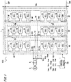
- Leistungswandlervorrichtung, die Folgendes aufweist:- einen Leistungswandler (1), der eine Vielzahl von Phasenzweigen (4U, 4V, 4W) enthält, bei dem ein erster Zweig (5U, 5V, 5W) und ein zweiter Zweig (6U, 6V, 6W) für jede der Phasen in Reihe miteinander verbunden sind, wobei die Vielzahl von Phasenzweigen (4U, 4V, 4W) parallel zwischen positiven und negativen Gleichstromleitungen angeschlossen sind, wobei der Leistungswandler (1) zur Durchführung einer Leistungsumwandlung zwischen dreiphasigem Wechselstrom und Gleichstrom ausgestaltet ist; und- eine Steuervorrichtung (50, 50A, 50B), die dazu ausgestaltet ist, jeweilige Spannungs-Befehlswerte für den ersten Zweig (5U, 5V, 5W) und den zweiten Zweig (6U, 6V, 6W) zu erzeugen und eine Treibersteuerung des Leistungswandlers (1) auf der Grundlage der Spannungs-Befehlswerte durchzuführen, wobei der erste Zweig (5U, 5V, 5W) und der zweite Zweig (6U, 6V, 6W) jeweils eine Wandlereinheit (10, 20, 20a) enthalten, die aufgebaut ist aus: einem ersten Reihenkörper (23, 35) mit Halbleiterschaltelementen (21s, 22s, 31s, 32s) sowohl in dem oberen als auch in dem unteren Zweig; und einem Gleichstromkondensator (29, 39), der parallel zum ersten Reihenkörper (23, 35) geschaltet ist,
wobei die Wandlereinheit (20, 20a) in dem zweiten Zweig (6U, 6V, 6W) eine zweite Wandlereinheit (20, 20a) ist, die durch Parallelschalten des Gleichstromkondensators (39), des ersten Reihenkörpers (23, 35), und eines zweiten Reihenkörpers (36, 36a) gebildet ist, wobei der zweite Reihenkörper (36, 36a) ein Halbleiterschaltelement (34s) in einem von dem oberen und dem unteren Zweig aufweist und eine Diode (33, 37d) in dem anderen aufweist, wobei die zweite Wandlereinheit (20, 20a) dazu ausgestaltet ist, Spannungen mit positiver und negativer Polarität auszugeben, die der Größe der Spannung über beiden Enden des Gleichstromkondensators (39) entsprechen,
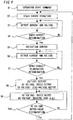
wobei dann, wenn ein Kurzschluss zwischen den Gleichstromleitungen detektiert wird, die Steuervorrichtung (50, 50A, 50B) dazu ausgestaltet ist, eine Schutzsteuerung durchzuführen, um die Halbleiterschaltelemente (21s, 22s, 31s, 32s, 34s, 37s) im Leistungswandler (1) auszuschalten, und
dadurch gekennzeichnet,
dass dann, wenn eine Beseitigung des Kurzschlusses zwischen den Gleichstromleitungen detektiert wird, die Steuervorrichtung (50, 50A, 50B) dazu ausgestaltet ist, eine Wiederanlaufsteuerung des Leistungswandlers (1) durchzuführen und einen Spannungs-Befehlswert einschließlich eines Gleichspannungs-Befehlswerts mit positiver Polarität an die Wandlereinheit (10) im ersten Zweig (5U, 5V, 5W) abzugeben und einen Spannungs-Befehlswert einschließlich eines Gleichspannungs-Befehlswerts, der allmählich von einer negativen Polarität zu einer positiven Polarität ansteigt, an die zweite Wandlereinheit (20, 20a) in dem zweiten Zweig (6U, 6V, 6W) abzugeben, so dass eine allmählich ansteigende Gleichspannung an die Gleichstromleitungen ausgegeben wird, während ein durch die Diode (33, 37d) fließender Strom negativer Polarität unter Verwendung einer Impedanz (ZP, ZN), die die Gleichstromleitungen haben, zu dem Phasenzweig (4U, 4V, 4W) fließt. - Leistungswandlervorrichtung nach Anspruch 1,
wobei der zweite Reihenkörper (36a) ein Halbleiterschaltelement (37s) in dem anderen aufweist, zu dem die Diode (37d) parallelgeschaltet ist, und
bei der Wiederanlaufsteuerung die Steuervorrichtung (50, 50A, 50B) dazu ausgestaltet ist, das Halbleiterschaltelement (37s) des anderen im zweiten Reihenkörper (36a) in einem AUS-Zustand zu fixieren. - Leistungswandlervorrichtung nach Anspruch 1 oder 2,
wobei bei der Wiederanlaufsteuerung, wenn die Beseitigung des Kurzschlusses zwischen den Gleichstromleitungen detektiert wird, die Steuervorrichtung (50, 50A, 50B) dazu ausgestaltet ist, der Wandlereinheit (10) im ersten Zweig (5U, 5V, 5W) einen Spannungs-Befehlswert einschließlich eines Nenn-Wechselspannungs-Befehlswerts und eines Gleichspannungs-Befehlswerts positiver Polarität zu liefern, und der zweiten Wandlereinheit (20, 20a) im zweiten Zweig (6U, 6V, 6W) einen Spannungs-Befehlswert einschließlich eines Nenn-Wechselspannungs-Befehlswerts und eines Gleichspannungs-Befehlswerts, der allmählich von einem Gleichspannungs-Befehlswert negativer Polarität auf einen Gleichspannungs-Befehlswert positiver Polarität ansteigt, zu liefern. - Leistungswandlervorrichtung nach einem der Ansprüche 1 bis 3,
wobei bei der Wiederanlaufsteuerung, wenn detektiert wird, dass die Spannung des Gleichstromkondensators (39) in der zweiten Wandlereinheit (20, 20a) außerhalb eines vorbestimmten Spannungswertbereichs liegt, die Steuervorrichtung (50, 50A, 50B) dazu ausgestaltet ist, einen Spannungs-Befehlswert für die zweite Wandlereinheit (20, 20a) in dem zweiten Zweig (6U, 6V, 6W) derart einzustellen, dass die Geschwindigkeit des allmählichen Anstiegs der Gleichspannung auf den Gleichstromleitungen schneller wird als die zum Zeitpunkt des Erfassens. - Leistungswandlervorrichtung nach einem der Ansprüche 1 bis 4,
wobei die Impedanz (ZP, ZN) eine Streuimpedanz zwischen den Gleichstromleitungen und einer Masse ist. - Leistungswandlervorrichtung nach einem der Ansprüche 1 bis 5,
wobei eine Kapazität (14) als Impedanz (ZP, ZN) zwischen der positiven und negativen Gleichstromleitung vorgesehen ist, und
wobei bei der Wiederanlaufsteuerung die Steuervorrichtung (50, 50A, 50B) dazu ausgestaltet ist, zu bewirken, dass der Strom negativer Polarität zum Phasenzweig (4U, 4V, 4W) über die Kapazität (14) fließt. - Leistungswandlervorrichtung nach einem der Ansprüche 1 bis 6,
wobei ein Widerstand (15r) als Impedanz (ZP, ZN) und ein erster Schalter (15s), der mit dem Widerstand in Reihe geschaltet ist, zwischen der positiven und negativen Gleichstromleitung vorgesehen sind, und
wobei dann, wenn die Beseitigung des Kurzschlusses zwischen den Gleichstromleitungen detektiert wird, die Steuervorrichtung (50, 50A, 50B) dazu ausgestaltet ist, die Wiederanlaufsteuerung durchzuführen, nachdem bewirkt worden ist, dass der erste Schalter (15s) geschlossen wird, und zu bewirken, dass der erste Schalter (15s) geöffnet wird, nachdem die Spannung der Gleichstromleitungen einen Nennspannungswertebereich erreicht hat. - Leistungswandlervorrichtung nach einem der Ansprüche 1 bis 7,
wobei alle Wandlereinheiten (10) in dem ersten Zweig (5U, 5V, 5W) erste Wandlereinheiten (10) sind, die jeweils durch Parallelschalten des Gleichstromkondensators (29) und des ersten Reihenkörpers (23) gebildet sind und eine Halbbrückenkonfiguration aufweisen. - Leistungswandlervorrichtung nach einem der Ansprüche 1 bis 7,
wobei alle Wandlereinheit (20, 20a) in dem ersten Zweig (5U, 5V, 5W) zweite Wandlereinheiten (20, 20a) sind. - Leistungswandlervorrichtung nach einem der Ansprüche 1 bis 7,
wobei der erste Zweig (5U, 5V, 5W) aufgebaut ist aus: einer ersten Wandlereinheit (10), die durch Parallelschalten des Gleichstromkondensators (29) und des ersten Reihenkörpers (23) gebildet ist, und eine Halbbrückenkonfiguration aufweist; und der zweiten Wandlereinheit (20, 20a). - Leistungswandlervorrichtung nach einem der Ansprüche 1 bis 10,
wobei die Summe der Ladespannungen der Gleichstromkondensatoren (39) der zweiten Wandlereinheiten (20, 20a), die in einen Kurzschluss-Stromweg des Leistungswandlers (1) geschaltet sind, wenn die Gleichstromleitungen kurzgeschlossen sind, höher ist als die Spannung zwischen Wechselstromleitungen des Leistungswandlers (1). - Leistungswandlervorrichtung nach Anspruch 2,
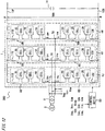
wobei bei stetiger Steuerung des Leistungswandlers (1) die Steuervorrichtung (50, 50A, 50B) dazu ausgestaltet ist, das Halbleiterschaltelement (37s) des anderen in dem zweiten Reihenkörper (36a) in einem AUS-Zustand zu fixieren. - Leistungssystem mit einer Vielzahl von Leistungswandlervorrichtungen (600A, 600B) nach einem der Ansprüche 1 bis 12,
wobei die Gleichstromleitungen der Leistungswandler (1) der Leistungswandlervorrichtungen (600A, 600B) miteinander verbunden sind. - Leistungssystem nach Anspruch 13,
wobei die Vielzahl von Leistungswandlervorrichtungen (600A, 600B) jeweils mit einem zweiten Schalter (16PA, 16NA, 16PB, 16NB) versehen ist, der mit einem Gleichstromanschluss auf einer Gleichstromseite des Leistungswandlers (1) verbunden ist, und über die zweiten Schalter (16PA, 16NA, 16PB, 16NB) mit den Gleichstromleitungen verbunden ist,
wobei dann, wenn ein Kurzschluss zwischen den Gleichstromleitungen detektiert wird, die Vielzahl von Leistungswandlervorrichtungen (600A, 600B) dazu ausgestaltet ist, zu bewirken, dass die jeweiligen zweiten Schalter (16PA, 16NA, 16PB, 16NB) geöffnet werden, und die Schutzsteuerung durchzuführen, und
wenn die Beseitigung des Kurzschlusses zwischen den Gleichstromleitungen detektiert wird, eine vorbestimmte Leistungswandlervorrichtung von der Vielzahl von Leistungswandlervorrichtungen (600A, 600B) dazu ausgestaltet ist, zu bewirken, dass der der vorbestimmten Leistungswandlervorrichtung (600A, 600B) zugeordnete zweite Schalter geschlossen wird, und nachdem detektiert worden ist, dass sich der der anderen Leistungswandlervorrichtung (600A, 600B) zugeordnete zweite Schalter in einem geöffneten Zustand befindet, die vorbestimmte Leistungswandlervorrichtung (600A, 600B) dazu ausgestaltet ist, die Wiederanlaufsteuerung durchzuführen.
Applications Claiming Priority (2)
| Application Number | Priority Date | Filing Date | Title |
|---|---|---|---|
| JP2016178473 | 2016-09-13 | ||
| PCT/JP2017/021147 WO2018051587A1 (ja) | 2016-09-13 | 2017-06-07 | 電力変換装置および電力システム |
Publications (3)
| Publication Number | Publication Date |
|---|---|
| EP3514941A1 EP3514941A1 (de) | 2019-07-24 |
| EP3514941A4 EP3514941A4 (de) | 2019-10-09 |
| EP3514941B1 true EP3514941B1 (de) | 2020-12-09 |
Family
ID=61619137
Family Applications (1)
| Application Number | Title | Priority Date | Filing Date |
|---|---|---|---|
| EP17850494.0A Active EP3514941B1 (de) | 2016-09-13 | 2017-06-07 | Leistungsumwandlungsvorrichtung und leistungssystem |
Country Status (4)
| Country | Link |
|---|---|
| US (1) | US10483871B2 (de) |
| EP (1) | EP3514941B1 (de) |
| JP (1) | JP6526344B2 (de) |
| WO (1) | WO2018051587A1 (de) |
Families Citing this family (14)
| Publication number | Priority date | Publication date | Assignee | Title |
|---|---|---|---|---|
| KR101923135B1 (ko) * | 2016-12-26 | 2018-11-28 | 효성중공업 주식회사 | 모듈러 멀티레벨 컨버터 시스템 |
| DE102017202204A1 (de) * | 2017-02-13 | 2018-08-16 | Siemens Aktiengesellschaft | Umrichteranordnung |
| EP3621193A1 (de) * | 2018-09-06 | 2020-03-11 | ABB Schweiz AG | Künstliche stabile kurzschluss-ausfallmodusfunktion durch verwendung paralleler module für jede schaltfunktion |
| EP3654510A1 (de) * | 2018-11-19 | 2020-05-20 | Maschinenfabrik Reinhausen GmbH | Vorladen eines modularen multilevel umrichters |
| WO2020108736A1 (en) * | 2018-11-27 | 2020-06-04 | Abb Schweiz Ag | Statcom arrangement without phase reactors |
| JP6545426B1 (ja) * | 2018-12-25 | 2019-07-17 | 三菱電機株式会社 | 電力変換装置 |
| EP3905504A4 (de) * | 2018-12-25 | 2021-12-15 | Mitsubishi Electric Corporation | Stromumwandlungsvorrichtung |
| US11171575B2 (en) * | 2019-04-22 | 2021-11-09 | The Regents Of The University Of California | Modular multilevel converter topologies |
| WO2021005792A1 (ja) * | 2019-07-11 | 2021-01-14 | 三菱電機株式会社 | 電力変換装置 |
| WO2021024463A1 (ja) * | 2019-08-08 | 2021-02-11 | 三菱電機株式会社 | 電力変換装置 |
| EP3780366A1 (de) * | 2019-08-13 | 2021-02-17 | Vestas Wind Systems A/S | Gleichstrom-chopper für mmc-zelle mit integriertem chopper-widerstand |
| CN112583244B (zh) * | 2019-09-29 | 2021-11-09 | 国创移动能源创新中心(江苏)有限公司 | 电力电子变压器系统直流母线电容的均压控制装置和方法 |
| JP6771707B1 (ja) * | 2020-03-11 | 2020-10-21 | 三菱電機株式会社 | 電力変換装置 |
| EP4262079A4 (de) * | 2020-12-09 | 2024-01-17 | Mitsubishi Electric Corp | Leistungswandler |
Family Cites Families (5)
| Publication number | Priority date | Publication date | Assignee | Title |
|---|---|---|---|---|
| CN101548461B (zh) * | 2006-12-08 | 2012-12-12 | 西门子公司 | 在电压中间电路变流器中用于控制直流侧的短路的半导体保护元件 |
| JP5894777B2 (ja) | 2011-12-07 | 2016-03-30 | 株式会社日立製作所 | 電力変換装置 |
| WO2015098146A1 (ja) * | 2013-12-24 | 2015-07-02 | 三菱電機株式会社 | 電力変換装置 |
| CN104300569B (zh) * | 2014-09-29 | 2016-04-20 | 华中科技大学 | 基于混合型mmc的hvdc直流侧短路故障穿越和恢复方法 |
| DE102015109466A1 (de) * | 2015-06-15 | 2016-12-15 | Ge Energy Power Conversion Technology Limited | Stromrichter-Submodul mit Kurzschlusseinrichtung und Stromrichter mit diesem |
-
2017
- 2017-06-07 JP JP2018539524A patent/JP6526344B2/ja active Active
- 2017-06-07 EP EP17850494.0A patent/EP3514941B1/de active Active
- 2017-06-07 US US16/311,872 patent/US10483871B2/en active Active
- 2017-06-07 WO PCT/JP2017/021147 patent/WO2018051587A1/ja active Application Filing
Also Published As
| Publication number | Publication date |
|---|---|
| JPWO2018051587A1 (ja) | 2019-01-17 |
| JP6526344B2 (ja) | 2019-06-05 |
| US20190207533A1 (en) | 2019-07-04 |
| EP3514941A1 (de) | 2019-07-24 |
| WO2018051587A1 (ja) | 2018-03-22 |
| EP3514941A4 (de) | 2019-10-09 |
| US10483871B2 (en) | 2019-11-19 |
Similar Documents
| Publication | Publication Date | Title |
|---|---|---|
| EP3514941B1 (de) | Leistungsumwandlungsvorrichtung und leistungssystem | |
| US10110110B2 (en) | Power conversion device | |
| JP6207730B2 (ja) | 直流送電電力変換装置および直流送電電力変換方法 | |
| EP2467928B1 (de) | Dreiphasige hochleistungs-usv | |
| US9608511B2 (en) | Method for charging modular multilevel converter | |
| EP3324531B1 (de) | Stromwandlungsvorrichtung | |
| US9960709B2 (en) | Power conversion device | |
| EP2587620B1 (de) | Spannungsausgleichsschaltung für DC Bus | |
| US10128741B2 (en) | Power conversion device | |
| EP3285388B1 (de) | Stromwandlungsvorrichtung | |
| EP3285380B1 (de) | Spannungsausgleich von spannungsquellenwandlers | |
| JPWO2019215842A1 (ja) | 電力変換装置 | |
| CA2405192C (en) | Power conversion apparatus | |
| US20180019685A1 (en) | Power converter | |
| US11716008B2 (en) | Power conversion device | |
| WO2024061964A1 (en) | Active filter pre-charging for a converter with active filter cells | |
| WO2020030245A1 (en) | A method of controlling an mmc |
Legal Events
| Date | Code | Title | Description |
|---|---|---|---|
| STAA | Information on the status of an ep patent application or granted ep patent |
Free format text: STATUS: THE INTERNATIONAL PUBLICATION HAS BEEN MADE |
|
| PUAI | Public reference made under article 153(3) epc to a published international application that has entered the european phase |
Free format text: ORIGINAL CODE: 0009012 |
|
| STAA | Information on the status of an ep patent application or granted ep patent |
Free format text: STATUS: REQUEST FOR EXAMINATION WAS MADE |
|
| 17P | Request for examination filed |
Effective date: 20190307 |
|
| AK | Designated contracting states |
Kind code of ref document: A1 Designated state(s): AL AT BE BG CH CY CZ DE DK EE ES FI FR GB GR HR HU IE IS IT LI LT LU LV MC MK MT NL NO PL PT RO RS SE SI SK SM TR |
|
| AX | Request for extension of the european patent |
Extension state: BA ME |
|
| A4 | Supplementary search report drawn up and despatched |
Effective date: 20190909 |
|
| RIC1 | Information provided on ipc code assigned before grant |
Ipc: H02M 7/49 20070101AFI20190903BHEP Ipc: H02M 7/483 20070101ALI20190903BHEP Ipc: H02M 7/797 20060101ALI20190903BHEP Ipc: H02M 1/00 20060101ALN20190903BHEP Ipc: H02M 1/32 20070101ALN20190903BHEP |
|
| DAV | Request for validation of the european patent (deleted) | ||
| DAX | Request for extension of the european patent (deleted) | ||
| GRAP | Despatch of communication of intention to grant a patent |
Free format text: ORIGINAL CODE: EPIDOSNIGR1 |
|
| STAA | Information on the status of an ep patent application or granted ep patent |
Free format text: STATUS: GRANT OF PATENT IS INTENDED |
|
| RIC1 | Information provided on ipc code assigned before grant |
Ipc: H02M 7/483 20070101ALI20200528BHEP Ipc: H02M 1/00 20060101ALN20200528BHEP Ipc: H02M 1/32 20070101ALN20200528BHEP Ipc: H02M 7/797 20060101ALI20200528BHEP Ipc: H02M 7/49 20070101AFI20200528BHEP |
|
| INTG | Intention to grant announced |
Effective date: 20200619 |
|
| GRAS | Grant fee paid |
Free format text: ORIGINAL CODE: EPIDOSNIGR3 |
|
| GRAA | (expected) grant |
Free format text: ORIGINAL CODE: 0009210 |
|
| STAA | Information on the status of an ep patent application or granted ep patent |
Free format text: STATUS: THE PATENT HAS BEEN GRANTED |
|
| AK | Designated contracting states |
Kind code of ref document: B1 Designated state(s): AL AT BE BG CH CY CZ DE DK EE ES FI FR GB GR HR HU IE IS IT LI LT LU LV MC MK MT NL NO PL PT RO RS SE SI SK SM TR |
|
| REG | Reference to a national code |
Ref country code: GB Ref legal event code: FG4D |
|
| REG | Reference to a national code |
Ref country code: AT Ref legal event code: REF Ref document number: 1344408 Country of ref document: AT Kind code of ref document: T Effective date: 20201215 Ref country code: CH Ref legal event code: EP |
|
| REG | Reference to a national code |
Ref country code: DE Ref legal event code: R096 Ref document number: 602017029433 Country of ref document: DE |
|
| REG | Reference to a national code |
Ref country code: IE Ref legal event code: FG4D |
|
| REG | Reference to a national code |
Ref country code: SE Ref legal event code: TRGR |
|
| PG25 | Lapsed in a contracting state [announced via postgrant information from national office to epo] |
Ref country code: FI Free format text: LAPSE BECAUSE OF FAILURE TO SUBMIT A TRANSLATION OF THE DESCRIPTION OR TO PAY THE FEE WITHIN THE PRESCRIBED TIME-LIMIT Effective date: 20201209 Ref country code: RS Free format text: LAPSE BECAUSE OF FAILURE TO SUBMIT A TRANSLATION OF THE DESCRIPTION OR TO PAY THE FEE WITHIN THE PRESCRIBED TIME-LIMIT Effective date: 20201209 Ref country code: NO Free format text: LAPSE BECAUSE OF FAILURE TO SUBMIT A TRANSLATION OF THE DESCRIPTION OR TO PAY THE FEE WITHIN THE PRESCRIBED TIME-LIMIT Effective date: 20210309 Ref country code: GR Free format text: LAPSE BECAUSE OF FAILURE TO SUBMIT A TRANSLATION OF THE DESCRIPTION OR TO PAY THE FEE WITHIN THE PRESCRIBED TIME-LIMIT Effective date: 20210310 |
|
| REG | Reference to a national code |
Ref country code: AT Ref legal event code: MK05 Ref document number: 1344408 Country of ref document: AT Kind code of ref document: T Effective date: 20201209 |
|
| PG25 | Lapsed in a contracting state [announced via postgrant information from national office to epo] |
Ref country code: BG Free format text: LAPSE BECAUSE OF FAILURE TO SUBMIT A TRANSLATION OF THE DESCRIPTION OR TO PAY THE FEE WITHIN THE PRESCRIBED TIME-LIMIT Effective date: 20210309 Ref country code: LV Free format text: LAPSE BECAUSE OF FAILURE TO SUBMIT A TRANSLATION OF THE DESCRIPTION OR TO PAY THE FEE WITHIN THE PRESCRIBED TIME-LIMIT Effective date: 20201209 |
|
| REG | Reference to a national code |
Ref country code: NL Ref legal event code: MP Effective date: 20201209 |
|
| PG25 | Lapsed in a contracting state [announced via postgrant information from national office to epo] |
Ref country code: NL Free format text: LAPSE BECAUSE OF FAILURE TO SUBMIT A TRANSLATION OF THE DESCRIPTION OR TO PAY THE FEE WITHIN THE PRESCRIBED TIME-LIMIT Effective date: 20201209 Ref country code: HR Free format text: LAPSE BECAUSE OF FAILURE TO SUBMIT A TRANSLATION OF THE DESCRIPTION OR TO PAY THE FEE WITHIN THE PRESCRIBED TIME-LIMIT Effective date: 20201209 |
|
| REG | Reference to a national code |
Ref country code: LT Ref legal event code: MG9D |
|
| PG25 | Lapsed in a contracting state [announced via postgrant information from national office to epo] |
Ref country code: RO Free format text: LAPSE BECAUSE OF FAILURE TO SUBMIT A TRANSLATION OF THE DESCRIPTION OR TO PAY THE FEE WITHIN THE PRESCRIBED TIME-LIMIT Effective date: 20201209 Ref country code: PT Free format text: LAPSE BECAUSE OF FAILURE TO SUBMIT A TRANSLATION OF THE DESCRIPTION OR TO PAY THE FEE WITHIN THE PRESCRIBED TIME-LIMIT Effective date: 20210409 Ref country code: SK Free format text: LAPSE BECAUSE OF FAILURE TO SUBMIT A TRANSLATION OF THE DESCRIPTION OR TO PAY THE FEE WITHIN THE PRESCRIBED TIME-LIMIT Effective date: 20201209 Ref country code: SM Free format text: LAPSE BECAUSE OF FAILURE TO SUBMIT A TRANSLATION OF THE DESCRIPTION OR TO PAY THE FEE WITHIN THE PRESCRIBED TIME-LIMIT Effective date: 20201209 Ref country code: LT Free format text: LAPSE BECAUSE OF FAILURE TO SUBMIT A TRANSLATION OF THE DESCRIPTION OR TO PAY THE FEE WITHIN THE PRESCRIBED TIME-LIMIT Effective date: 20201209 Ref country code: CZ Free format text: LAPSE BECAUSE OF FAILURE TO SUBMIT A TRANSLATION OF THE DESCRIPTION OR TO PAY THE FEE WITHIN THE PRESCRIBED TIME-LIMIT Effective date: 20201209 Ref country code: EE Free format text: LAPSE BECAUSE OF FAILURE TO SUBMIT A TRANSLATION OF THE DESCRIPTION OR TO PAY THE FEE WITHIN THE PRESCRIBED TIME-LIMIT Effective date: 20201209 |
|
| PG25 | Lapsed in a contracting state [announced via postgrant information from national office to epo] |
Ref country code: AT Free format text: LAPSE BECAUSE OF FAILURE TO SUBMIT A TRANSLATION OF THE DESCRIPTION OR TO PAY THE FEE WITHIN THE PRESCRIBED TIME-LIMIT Effective date: 20201209 Ref country code: PL Free format text: LAPSE BECAUSE OF FAILURE TO SUBMIT A TRANSLATION OF THE DESCRIPTION OR TO PAY THE FEE WITHIN THE PRESCRIBED TIME-LIMIT Effective date: 20201209 |
|
| REG | Reference to a national code |
Ref country code: DE Ref legal event code: R097 Ref document number: 602017029433 Country of ref document: DE |
|
| PG25 | Lapsed in a contracting state [announced via postgrant information from national office to epo] |
Ref country code: IS Free format text: LAPSE BECAUSE OF FAILURE TO SUBMIT A TRANSLATION OF THE DESCRIPTION OR TO PAY THE FEE WITHIN THE PRESCRIBED TIME-LIMIT Effective date: 20210409 |
|
| PLBE | No opposition filed within time limit |
Free format text: ORIGINAL CODE: 0009261 |
|
| STAA | Information on the status of an ep patent application or granted ep patent |
Free format text: STATUS: NO OPPOSITION FILED WITHIN TIME LIMIT |
|
| PG25 | Lapsed in a contracting state [announced via postgrant information from national office to epo] |
Ref country code: IT Free format text: LAPSE BECAUSE OF FAILURE TO SUBMIT A TRANSLATION OF THE DESCRIPTION OR TO PAY THE FEE WITHIN THE PRESCRIBED TIME-LIMIT Effective date: 20201209 Ref country code: AL Free format text: LAPSE BECAUSE OF FAILURE TO SUBMIT A TRANSLATION OF THE DESCRIPTION OR TO PAY THE FEE WITHIN THE PRESCRIBED TIME-LIMIT Effective date: 20201209 |
|
| 26N | No opposition filed |
Effective date: 20210910 |
|
| PG25 | Lapsed in a contracting state [announced via postgrant information from national office to epo] |
Ref country code: DK Free format text: LAPSE BECAUSE OF FAILURE TO SUBMIT A TRANSLATION OF THE DESCRIPTION OR TO PAY THE FEE WITHIN THE PRESCRIBED TIME-LIMIT Effective date: 20201209 Ref country code: SI Free format text: LAPSE BECAUSE OF FAILURE TO SUBMIT A TRANSLATION OF THE DESCRIPTION OR TO PAY THE FEE WITHIN THE PRESCRIBED TIME-LIMIT Effective date: 20201209 |
|
| PG25 | Lapsed in a contracting state [announced via postgrant information from national office to epo] |
Ref country code: MC Free format text: LAPSE BECAUSE OF FAILURE TO SUBMIT A TRANSLATION OF THE DESCRIPTION OR TO PAY THE FEE WITHIN THE PRESCRIBED TIME-LIMIT Effective date: 20201209 Ref country code: ES Free format text: LAPSE BECAUSE OF FAILURE TO SUBMIT A TRANSLATION OF THE DESCRIPTION OR TO PAY THE FEE WITHIN THE PRESCRIBED TIME-LIMIT Effective date: 20201209 |
|
| REG | Reference to a national code |
Ref country code: CH Ref legal event code: PL |
|
| REG | Reference to a national code |
Ref country code: BE Ref legal event code: MM Effective date: 20210630 |
|
| PG25 | Lapsed in a contracting state [announced via postgrant information from national office to epo] |
Ref country code: LU Free format text: LAPSE BECAUSE OF NON-PAYMENT OF DUE FEES Effective date: 20210607 |
|
| PG25 | Lapsed in a contracting state [announced via postgrant information from national office to epo] |
Ref country code: LI Free format text: LAPSE BECAUSE OF NON-PAYMENT OF DUE FEES Effective date: 20210630 Ref country code: IE Free format text: LAPSE BECAUSE OF NON-PAYMENT OF DUE FEES Effective date: 20210607 Ref country code: CH Free format text: LAPSE BECAUSE OF NON-PAYMENT OF DUE FEES Effective date: 20210630 |
|
| PG25 | Lapsed in a contracting state [announced via postgrant information from national office to epo] |
Ref country code: IS Free format text: LAPSE BECAUSE OF FAILURE TO SUBMIT A TRANSLATION OF THE DESCRIPTION OR TO PAY THE FEE WITHIN THE PRESCRIBED TIME-LIMIT Effective date: 20210409 |
|
| PG25 | Lapsed in a contracting state [announced via postgrant information from national office to epo] |
Ref country code: BE Free format text: LAPSE BECAUSE OF NON-PAYMENT OF DUE FEES Effective date: 20210630 |
|
| P01 | Opt-out of the competence of the unified patent court (upc) registered |
Effective date: 20230512 |
|
| PG25 | Lapsed in a contracting state [announced via postgrant information from national office to epo] |
Ref country code: CY Free format text: LAPSE BECAUSE OF FAILURE TO SUBMIT A TRANSLATION OF THE DESCRIPTION OR TO PAY THE FEE WITHIN THE PRESCRIBED TIME-LIMIT Effective date: 20201209 |
|
| REG | Reference to a national code |
Ref country code: DE Ref legal event code: R084 Ref document number: 602017029433 Country of ref document: DE |
|
| PG25 | Lapsed in a contracting state [announced via postgrant information from national office to epo] |
Ref country code: HU Free format text: LAPSE BECAUSE OF FAILURE TO SUBMIT A TRANSLATION OF THE DESCRIPTION OR TO PAY THE FEE WITHIN THE PRESCRIBED TIME-LIMIT; INVALID AB INITIO Effective date: 20170607 |
|
| PGFP | Annual fee paid to national office [announced via postgrant information from national office to epo] |
Ref country code: FR Payment date: 20230510 Year of fee payment: 7 Ref country code: DE Payment date: 20230502 Year of fee payment: 7 |
|
| PGFP | Annual fee paid to national office [announced via postgrant information from national office to epo] |
Ref country code: SE Payment date: 20230510 Year of fee payment: 7 |
|
| PGFP | Annual fee paid to national office [announced via postgrant information from national office to epo] |
Ref country code: GB Payment date: 20230427 Year of fee payment: 7 |
|
| REG | Reference to a national code |
Ref country code: GB Ref legal event code: 746 Effective date: 20240325 |
|
| PG25 | Lapsed in a contracting state [announced via postgrant information from national office to epo] |
Ref country code: MK Free format text: LAPSE BECAUSE OF FAILURE TO SUBMIT A TRANSLATION OF THE DESCRIPTION OR TO PAY THE FEE WITHIN THE PRESCRIBED TIME-LIMIT Effective date: 20201209 |