EP3513219B1 - Fast recovery from incorrect carrier phase integer locking - Google Patents
Fast recovery from incorrect carrier phase integer locking Download PDFInfo
- Publication number
- EP3513219B1 EP3513219B1 EP17767959.4A EP17767959A EP3513219B1 EP 3513219 B1 EP3513219 B1 EP 3513219B1 EP 17767959 A EP17767959 A EP 17767959A EP 3513219 B1 EP3513219 B1 EP 3513219B1
- Authority
- EP
- European Patent Office
- Prior art keywords
- state
- filter
- carrier phase
- determining
- consistent
- Prior art date
- Legal status (The legal status is an assumption and is not a legal conclusion. Google has not performed a legal analysis and makes no representation as to the accuracy of the status listed.)
- Active
Links
Images


Classifications
-
- G—PHYSICS
- G01—MEASURING; TESTING
- G01S—RADIO DIRECTION-FINDING; RADIO NAVIGATION; DETERMINING DISTANCE OR VELOCITY BY USE OF RADIO WAVES; LOCATING OR PRESENCE-DETECTING BY USE OF THE REFLECTION OR RERADIATION OF RADIO WAVES; ANALOGOUS ARRANGEMENTS USING OTHER WAVES
- G01S19/00—Satellite radio beacon positioning systems; Determining position, velocity or attitude using signals transmitted by such systems
- G01S19/38—Determining a navigation solution using signals transmitted by a satellite radio beacon positioning system
- G01S19/39—Determining a navigation solution using signals transmitted by a satellite radio beacon positioning system the satellite radio beacon positioning system transmitting time-stamped messages, e.g. GPS [Global Positioning System], GLONASS [Global Orbiting Navigation Satellite System] or GALILEO
- G01S19/42—Determining position
- G01S19/43—Determining position using carrier phase measurements, e.g. kinematic positioning; using long or short baseline interferometry
- G01S19/44—Carrier phase ambiguity resolution; Floating ambiguity; LAMBDA [Least-squares AMBiguity Decorrelation Adjustment] method
-
- G—PHYSICS
- G01—MEASURING; TESTING
- G01S—RADIO DIRECTION-FINDING; RADIO NAVIGATION; DETERMINING DISTANCE OR VELOCITY BY USE OF RADIO WAVES; LOCATING OR PRESENCE-DETECTING BY USE OF THE REFLECTION OR RERADIATION OF RADIO WAVES; ANALOGOUS ARRANGEMENTS USING OTHER WAVES
- G01S19/00—Satellite radio beacon positioning systems; Determining position, velocity or attitude using signals transmitted by such systems
- G01S19/01—Satellite radio beacon positioning systems transmitting time-stamped messages, e.g. GPS [Global Positioning System], GLONASS [Global Orbiting Navigation Satellite System] or GALILEO
- G01S19/13—Receivers
- G01S19/23—Testing, monitoring, correcting or calibrating of receiver elements
-
- G—PHYSICS
- G01—MEASURING; TESTING
- G01S—RADIO DIRECTION-FINDING; RADIO NAVIGATION; DETERMINING DISTANCE OR VELOCITY BY USE OF RADIO WAVES; LOCATING OR PRESENCE-DETECTING BY USE OF THE REFLECTION OR RERADIATION OF RADIO WAVES; ANALOGOUS ARRANGEMENTS USING OTHER WAVES
- G01S19/00—Satellite radio beacon positioning systems; Determining position, velocity or attitude using signals transmitted by such systems
- G01S19/38—Determining a navigation solution using signals transmitted by a satellite radio beacon positioning system
- G01S19/39—Determining a navigation solution using signals transmitted by a satellite radio beacon positioning system the satellite radio beacon positioning system transmitting time-stamped messages, e.g. GPS [Global Positioning System], GLONASS [Global Orbiting Navigation Satellite System] or GALILEO
- G01S19/42—Determining position
- G01S19/421—Determining position by combining or switching between position solutions or signals derived from different satellite radio beacon positioning systems; by combining or switching between position solutions or signals derived from different modes of operation in a single system
- G01S19/426—Determining position by combining or switching between position solutions or signals derived from different satellite radio beacon positioning systems; by combining or switching between position solutions or signals derived from different modes of operation in a single system by combining or switching between position solutions or signals derived from different modes of operation in a single system
Definitions
- Satellite positioning systems broadcast positioning signals from a constellation of satellites that can be used by a device with an SPS receiver to determine the position and/or velocity of the device.
- Example SPS include Global Positioning System (GPS), Global Navigation Satellite System (GNSS), Galileo, GLONASS, Beidou (Compass), etc.
- GPS Global Positioning System
- GNSS Global Navigation Satellite System
- Galileo Galileo
- GLONASS Beidou
- each satellite in an SPS broadcasts signals using at least one carrier frequency.
- the GPS system for example, uses two carrier frequencies: 1575. 4 MHz and 1227.6 MHz.
- Other SPSs may use more than two carrier frequencies or just one carrier frequency.
- Signals broadcast from an SPS satellite are conventionally modulated with a pseudo-random code (PRC).
- the PRC may also be referred to as a spreading code because it spreads the frequency spectrum of the signal over a particular range of frequencies (e.g., 1 MHz bandwidth).
- An SPS receiver receives the signal from the SPS satellite and determines a time of arrival (TOA) of the signal by correlating the received signal with a locally generated PRC. In this way, the distance between the SPS receiver and the satellite can be determined by, for example, determining the transit time of the signal (the difference in time between when the signal was received and when the satellite transmitted the signal) and multiplying that transit time by the speed of light.
- the distance between the satellite and the receiver is referred to as the pseudorange or a code phase measurement. Due to the limited bandwidth of the PRC (e.g., 1 MHz) and noise, the accuracy of the pseudorange measurement is on the order of one meter. However, if a carrier phase measurement is performed and used to determine the location of the receiver, the accuracy of the location of the receiver can be increased to on the order of one centimeter.
- the invention relates to a method of determining a position of a device using a signal received from a reference emitter being a satellite of a satellite positioning system, the method comprising: receiving, with a receiver of the device, the signal from the reference emitter; determining a state of a first filter based on the signal, wherein the state of the first filter includes a first carrier phase ambiguity estimate comprising a floating value; determining a state of a second filter based on the signal, wherein the state of the second filter includes a second carrier phase ambiguity estimate comprising a fixed integer value; determining whether the state of the second filter is consistent with the state of the first filter; maintaining the state of the second filter in response to the device determining that the state of the second filter is consistent with the state of the first filter; changing the state of the second filter to the state of the first filter in response to the device determining that the state of the second filter is not consistent with the
- the first filter may be a first Kalman filter and the second filter may be a second Kalman filter.
- the method may include fixing the second carrier phase ambiguity estimate by setting a covariance matrix term associated with the second carrier phase ambiguity estimate to be equal to or approximately equal to zero.
- the invention also relates to a device for determining a position of itself using a signal received from a reference emitter being a satellite of a satellite positioning system, the device comprising: receiving means for wirelessly receiving the signal from the reference emitter; first filtering means for determining a first state based on the signal, wherein the first state includes a first carrier phase ambiguity estimate comprising a floating value; second filtering means for determining a second state based on the signal, wherein the second state includes a second carrier phase ambiguity estimate comprising a fixed integer value; determining means for determining whether the second state is consistent with the first state; maintaining means for maintaining the second state in response to the device determining that the second state is consistent with the first state; changing means for changing the second state to the first state in response to the device determining that the second state is not consistent with the first state; and positioning means for determining the position of the device based on the second state.
- Implementations of such a device may include one or more of the following features.
- the processor may be configured to determine whether the state of the second filter is consistent with the state of the first filter by determining whether an estimate from the state of the second filter is consistent with a variance of an estimate from the state of the first filter.
- the first filter may be a first Kalman filter and the second filter may be a second Kalman filter.
- the processor may be configured to fix the second carrier phase ambiguity estimate by setting a covariance matrix term associated with the second carrier phase ambiguity estimate to be equal to or approximately equal to zero.
- the invention also relates to a non-transitory processor-readable storage medium comprising processor-readable instructions configured to cause a processor of a device comprising receiving means for wirelessly receiving a signal from a satellite of a satellite positioning system to receive a signal from a reference emitter, wherein the reference emitter is a satellite of a satellite positioning system; determine a state of a first filter based on the signal, wherein the state of the first filter includes a first carrier phase ambiguity estimate comprising a floating value; determine a state of a second filter based on the signal, wherein the state of the second filter includes a second carrier phase ambiguity estimate comprising a fixed integer value; determine whether the state of the second filter is consistent with the state of the first filter; maintain the state of the second filter in response to the device determining that the state of the second filter is consistent with the state of the first filter; change the state of the second filter to the state of the first filter in response to the device determining that the state of the second filter is not consistent with the state of the first filter; and
- Implementations of such a non-transitory processor-readable storage medium may include one or more of the following features.
- the instructions configured to cause the processor to determine whether the state of the second filter is consistent with the state of the first filter may include instructions configured to cause the processor to determine whether the state of the second filter is consistent with a variance of an estimate from the state of the first filter.
- the first filter may be a first Kalman filter and the second filter may be a second Kalman filter.
- the non-transitory processor-readable storage medium may further include instructions configured to cause the processor of the device to fix the second carrier phase ambiguity estimate by setting a covariance matrix term associated with the second carrier phase ambiguity estimate to be equal to or approximately equal to zero.
- Information such as location information, can be sent from a mobile device to a server even in situations where a condition would prevent the mobile device from sending the information at the scheduled time.
- SPS receivers provide two types of measurements: code phase measurements and carrier phase measurements.
- the code phase measurements typically have a noise standard deviation on the order of 1-2 meters.
- the carrier phase measurements may be much more precise with a noise standard deviation on the order of 1-2 centimeters.
- the carrier phase measurements are generally only specified up to an initially unknown ambiguity term, which is equal to an integer value times the carrier wavelength. Accordingly, determining a precise position of an SPS receiver includes resolving of the ambiguity of the unknown integer value through an integer fixing process.
- an integer fixing process is performed inside a Kalman filter.
- the filter may initially compute a float solution, which disregards the integer nature of the ambiguities. Once this float solution is close enough to an integer solution, the ambiguities in the filter are forced (or fixed) to this integer value and the corresponding entries in the filter covariance matrix are set to zero or some small value.
- This approach is susceptible to catastrophic filter failure if receiver noise causes the ambiguities in the filter to be incorrectly fixed to the wrong integer value. To avoid such a failure, prior systems are extremely conservative in fixing the integer ambiguities. This conservative approach may avoid catastrophic filter failure, but it also typically results in long delays from the time the receiver is turned on until a precise solution with fixed ambiguities is available.
- a fast integer ambiguity approach as described herein allows for fast fixing of the integer ambiguities and reduces the potential for a catastrophic filter failure.
- two Kalman filters are run in parallel.
- the first filter includes a state with floating carrier phase ambiguities and the second filter includes a state with fixed carrier phase ambiguities.
- the floating Kalman filter is updated with the measurements to produce the next float solution state and the fixed Kalman filter is updated with the measurements to produce the next fixed solution state. If the of the fixed solution state passes validation, it is incorporated in the fixed Kalman filter.
- the consistency of the fixed state may be verified by determining if the innovations of the fixed filter, or some other measurement prediction residual, are abnormal and/or determining if the fixed filter solution is diverging from the float filter solution. If the consistency of the fixed Kalman filter cannot be verified, then the fixed Kalman filter can be recovered by replacing the fixed state with the solution of the floating filter. In an example, the position may then be determined based on this recovered float solution.
- An SPS 1 includes a device 10 and a constellation of four satellites 15-18.
- the device 10 includes an antenna 11.
- Each of the satellites 15-18 emits a signal that is received by the antenna 11 and used by the device 10 to determine the position of the device based on the time of arrivals of the signals.
- FIG. 1 illustrates only a single signal 12 emitted by satellite 15.
- the satellites 16-18 emit signals similar to the signal 12 and can be received by the device 10.
- the signal 12 for purposes of illustrating the carrier phase ambiguity, is illustrated as two separate signals: a carrier signal 12a and a code signal 12b.
- the carrier signal 12a has a wavelength ⁇ carrier and the code signal 12b has a wavelength ⁇ code , which is greater than ⁇ carrier .
- the code signal 12b is a pseudo-random code (PRC) signal that repeats with a frequency that corresponds to the wavelength ⁇ code .
- PRC pseudo-random code
- the device 10 includes an SPS receiver that is operably coupled to the antenna 11 and includes a carrier phase tracking loop for monitoring the carrier phase of the signal 12. Once the carrier phase tracking loop locks to the signal, an initial fractional carrier phase, ⁇ , is determined. The device 10, however, cannot initially determine the total carrier phase of the signal 12 because the ambiguity of the carrier phase. That is, as depicted in FIG. 1 , the total carrier phase is the sum of the integer number of wavelengths between the satellite 15 and the antenna 11 plus the fractional carrier phase, phase, ⁇ .
- the device 10 may determine the fractional carrier phase to be 0.7 times the carrier wavelength, ⁇ carrier , and the integer number of wavelengths between the satellite 15 and the antenna 11 may be 143 carrier phase wavelengths, making the total carrier phase difference equal to 143.7 times ⁇ carrier .
- the integer number of wavelengths between the satellite 15 and the antenna 11 is referred to as the carrier phase ambiguity.
- the code phase of the signal 12 is determined by the device 10. There is no ambiguity in the code phase as the exact number of integer wavelengths, ⁇ code , can be determined by the mobile device 10. Consequently, an approximate value of the carrier phase ambiguity can be estimated based on the code phase measurement. This initial estimate is, for example, within about 50 wavelengths of the actual value of the carrier phase ambiguity.
- the carrier phase ambiguity can be determined as the actual number of wavelengths between the between the satellite 15 and the antenna 11, or as a relative number of wavelengths relative to the last integer code signal wavelength, referred to as the relative carrier phase ambiguity.
- the carrier phase ambiguity is one of several parameters of a state that is determined by the Kalman filter. Other state parameters may include an estimate of the three-dimensional position of the device, a clock bias estimate, and a clock drift estimate.
- the Kalman filter initially computes what is referred to as a "float solution,” which disregards the integer nature of the carrier phase ambiguity. After a number of measurements are made, the float solution becomes close enough to an integer solution for the Kalman filter to fix the ambiguity value to an integer value, referred to as a "fixed solution.”
- the carrier phase ambiguity estimate in the Kalman filter is fixed, the other parameters of the Kalman filter state are recalculated. Subsequent estimates of the location of the device that are made with the Kalman filter having a fixed solution for the carrier phase ambiguity are more accurate than position estimates made using the floating solution.
- the device 10 uses two Kalman filters operated in parallel.
- a first Kalman filter does not fix the carrier phase ambiguity, always maintaining a floating solution to the carrier phase ambiguity.
- This first Kalman filter is referred to as "a floating filter.”
- a second Kalman filter initially operates with a floating solution of the carrier phase ambiguity, but fixes the carrier phase ambiguity to an integer value after a shorter period of time than conventional techniques allow.
- This second Kalman filter is referred to as "a fixed filter.” The state of the second Kalman filter is used to determine the location of the device.
- the second Kalman filter By fixing the second Kalman filter sooner, the amount of time from starting positioning measurements to obtaining precise positioning solutions is reduced relative to techniques that wait a longer time to fix the carrier phase ambiguity.
- fixing the carrier phase ambiguity earlier than conventional techniques there is an increased risk of fixing on the incorrect integer value of the carrier phase ambiguity.
- the incorrect carrier phase ambiguity fix can be corrected using the state of the first Kalman filter. In this way, the second Kalman filter can quickly recover from an incorrect fix.
- the device 10 is a computer system that includes the antenna 11, a processor 30, a memory 31, an SPS receiver 33, a display 34, and sensors 35.
- the device 10 may be a handheld mobile device, such as a mobile phone or smart phone, or a navigation device used by an individual or a vehicle, such as an automobile, boat, or airplane.
- the device 10 includes one or more transceivers (not shown) for communicating with a cellular communication network by transmitting wireless signals to cellular base stations, such as wireless base transceiver stations (BTS), Node Bs, evolved NodeBs (eNB), etc.
- BTS wireless base transceiver stations
- eNB evolved NodeBs
- device 10 may include other wireless transceivers (not shown) for transmitting wireless signals to and receiving wireless signals from local transceivers such as Wi-Fi access points (AP), femtocells, Home Base Stations, small cell base stations, Home Node Bs (HNB) or Home eNodeBs (HeNB) and may provide access to a wireless local area network (WLAN, e.g., IEEE 802.11 network), a wireless personal area network (WPAN, e.g., Bluetooth® network or ZigBee® network) or a cellular network (e.g. an LTE network or other wireless wide area network such as those discussed in the next paragraph).
- WLAN wireless local area network
- WPAN wireless personal area network
- WLAN wireless personal area network
- cellular network e.g. an LTE network or other wireless wide area network such as those discussed in the next paragraph.
- the antenna 11 receives the wireless signal 12 from the satellite 15, as well as the signals emitted by the other satellites 16-18 in the SPS 1.
- the SPS receiver 33 is a wireless receiver for receiving the signal 12 from the satellite 15 via the antenna 11.
- the SPS receiver 33 includes the necessary systems (not shown) for measuring the code phase, carrier phase and Doppler shift of the signal 12, such as a delay lock loop and a phase lock loop.
- the SPS 1 may be a Global Positioning System (GPS), Global Navigation Satellite System (GNSS), Galileo, GLONASS, Beidou (Compass), etc.
- the processor 30 is an intelligent device, e.g., a central processing unit (CPU) such as those made or designed by Qualcomm®, ARM®, Intel® Corporation, or AMD®, a microcontroller, an application specific integrated circuit (ASIC), etc.
- the memory 31 is non-transitory, processor-readable memory that stores instructions that may be executed by processor 30 and includes random access memory (RAM), read-only memory (ROM) and non-volatile memory such as flash memory or solid state storage.
- the display 34 may be a liquid-crystal display (LCD) (e.g., a thin-film transistor (TFT) display), although other forms of displays are acceptable.
- LCD liquid-crystal display
- TFT thin-film transistor
- the display 34 displays location information to a user of the device by, for example, displaying coordinates and/or a graphical representation of the position of the device 10 on a map.
- Software 32 can be loaded onto the memory 31 by being downloaded via a network connection, uploaded from a disk, etc. Further, the software 32 may not be directly executable, e.g., requiring compiling before execution.
- the software 32 includes instructions configured to cause the processor 30 to perform functions described below.
- the various components of the mobile device 10 are communicatively coupled to one another via bus 36. While FIG. 2 illustrates the processor 30 and the memory 31 being separate from the SPS receiver 33, the processor 30 and memory 31 may be components of the SPS receiver 33 such that the processing of the SPS signal is performed by the SPS receiver.
- the sensors 35 make measurements of the environment and/or conditions experienced by the device 10.
- the sensors 35 may include inertial sensors, such a gyroscopes and accelerometers, that may provide measurements of the position, orientation, velocity and acceleration of the device 10.
- the sensors 35 may also include a pressure sensor that may provide pressure measurements that can be used to determine elevation measurements. The output from the sensors 35 may be used to check the consistency of states of filters used by the device 10.
- the processor 30 is communicatively coupled to the SPS receiver 33, the sensors 35, and the memory 31 via the bus 36.
- the processor 30 is configured to obtain the signal 12 from the SPS receiver 33 and determine the location of the device 10 from the signal 12 and the other signals received from the other satellites 16-18 of the SPS constellation.
- the processor 30 is also configured to obtain measurements from the sensor 35 and the SPS receiver 33 to determine the consistency of a state of the fixed filter of the device 10.
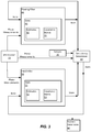
- the processor 30 is configured to determine a state of a first filter based on the signal 12.
- the SPS receiver 33 performs code phase and carrier phase measurements of the signal 12 and the measurement results are passed to the first filter, which is referred to as a floating filter 40 because the estimate of the carrier phase ambiguity determined by the first filter is a floating value that is not fixed to be an integer value.
- the floating filter 40 is a recursive filter that estimates a state 41 comprising multiple variables.
- the floating filter 40 may be a Kalman filter, an extended Kalman filter, a Bayes filter, or a particle filter.
- the state 41 of the floating filter 40 includes estimates 42 of the variables comprising the state and a covariance matrix 43 that relates the uncertainty of the multiple variables to one another.
- the variables that may be estimated by the floating filter 40 and included in the state 41 include: a three-dimensional position of the device (e.g., x, y, and z coordinates) and a clock bias, a clock drift, and a carrier phase ambiguity for each satellite from which signals are received.
- the processor 30 is also configured to determine a state of a second filter based on the signal 12.
- the SPS receiver 33 sends the carrier phase and code phase measurement results to the second filter, which is referred to as a fixed filter 50 because the estimate of the carrier phase ambiguity determined by the first filter is a fixed value that is forced, by the processor 30, to be an integer value.
- the fixed filter 50 is a recursive filter that estimates a state 51 comprising multiple variables.
- the fixed filter 50 may be a Kalman filter, an extended Kalman filter, a Bayes filter, or a particle filter.
- the fixed filter 50 is the same type of filter as the floating filter 40.
- the state 51 of the fixed filter 50 includes estimates 52 of the variables comprising the state and a covariance matrix 53 that relates the uncertainty of the multiple variables to one another.
- the variables that may be estimated by the floating filter 40 and included in the state 41 include: a three-dimensional position of the device (e.g., x, y, and z coordinates), and a clock bias, a clock drift, and a carrier phase ambiguity for each satellite from which signals are received.
- the state 41 of the floating filter 40 and the state 51 of the fixed filter 51 are updated when new signal are received, or every epoch of the SPS.
- the fixed filter 51 may not initially fix the carrier phase ambiguity to an integer value - it may be allowed to float for a period of time before being fixed.
- the processor 30 may be configured to fix the carrier phase ambiguity estimate of the state 51 by setting one or more terms of the covariance matrix 53 associated with the second carrier phase ambiguity to zero or approximately equal to zero. By setting these terms of the covariance matrix 53 the terms are fixed and not allowed to vary when the state 51 of the filter is updated.
- the processor 30 is configured to implement a consistency determiner 60 for determining whether the state 51 of the fixed filter 50 is consistent with at least one other filter state or a measurement. To perform the consistency determination, the processor 30 receives both the state 41 from the floating filter 40 and the state 51 from the fixed filter 50.
- the at least one other state to which the consistency determiner 60 compares the state 51 from the fixed filter 50 may be the state 41 from the floating filter 40 and/or a previous state of the fixed filter 50. Previous states of each filter may be stored in memory 31 so that the state 51 of the fixed filter 50 can be compared to previous states of either filter.
- the consistency determiner 60 may also determine whether the state 51 of the fixed filter 50 is consistent with one or more measurements, such as the code phase measurements and/or carrier phase measurements from the SPC receiver 33 or measurements from sensors 35, which can include elevation measurements, orientation measurements, and acceleration measurements.
- the consistency determiner 60 may determine whether a measurement prediction residual based on a current measurement is consistent with a variance of the measurement prediction residual from the previous filter state.
- the measurement prediction residual is a difference between the current measurement and a prediction of the current measurement based on the previous state of the fixed filter 50.
- the measurement prediction residual may comprise an innovation or a whitened measurement determined from the fixed filter and the current measurement.
- the previous state of the fixed filter 50 is used to determine a prediction of the current state of the fixed filter, which is then used to predict the current measurement.
- the difference between the actual current measurement and the prediction of the current measurement is the measurement prediction residual.
- the measurement prediction residual can then be used to determine a prediction of the next state of the fixed filter 50.
- the previous state of the fixed filter 50 may include a position and velocity estimate of the device. Based on the position and velocity from the previous state and a previous measurement prediction residual determination, the current state of the fixed filter 50 can be predicted.
- the variance of the measurement prediction residual can also be determined from the variances of the previous state of the fixed filter. If the measurement prediction residual is outside the variance determined based on the covariance matrix from the previous state, then the measurement is determined to be inconsistent with the previous state. To be considered outside the variance, the measurement prediction residual may be 1-2 standard deviations away from the measurement prediction residual predicted based on the previous state.
- a chi squared random variable may be used to determine if the measurement prediction residual is consistent with a statistical model based on the previous state of the fixed filter 50.
- the state 51 of the fixed filter is consistent with the previous state of the fixed filter 50 when the measurement prediction residual is within the noise expected based on the previous state of the fixed filter 50.
- a 95% or 99% threshold value may be set such that if the consistency determiner 60 determines that the estimates 52 of the state 51 result in an measurement prediction residual that is less than 5% or 1% (respectively) likely to be described by the statistical model based on the previous state of the fixed filter 50, then the state 51 of the fixed filter is not consistent with the previous state of the fixed filter 50.
- the aforementioned measurement may be received by the consistency determiner 60 from SPS Receiver 33 or sensors 35.
- the measurement may be a code phase measurement, a carrier phase measurement, a Doppler measurement, an elevation measurement, an orientation measurement, or an acceleration measurement.
- the consistency determiner 60 may determine whether an estimate from the state 51 of the fixed filter 50 is consistent with a variance of an estimate from the state 41 of the floating filter 40. For example, if one or more of the estimates 52 of the state 51 is outside the variances found in the covariance matrix from the state 41 of the floating filter 40, then the measurement is determined to be inconsistent with the state 41 of the floating filter 41. To be considered outside the variances of the floating state 41, the one or more estimates 52 of the state 51 may be 1-2 standard deviations away from the estimate of the variable in the state 41 of the floating filter 40.
- a chi squared random variable may be used to determine if the estimates 52 are consistent with a statistical model based on the state 41 of the floating filter 40.
- the state 51 of the fixed filter is consistent with the state 41 of the floating filter 40 when the state 51 is within the noise expected based on the state 41 of the floating filter 40.
- a 95% or 99% threshold value may be set such that if the consistency determiner 60 determines that the estimates 52 of the state 51 are less than 5% or 1% (respectively) likely to be described by the statistical model based on the state 41 of the floating filter 40, then the state 51 of the fixed filter is not consistent with the state 41 of the floating filter 40.
- the fixed filter maintains the state of the fixed filter 50 until the next epoch when it will be updated based on new measurement information.
- the consistency determiner 60 determines that the state 51 of the fixed filter 50 is not consistent with the at least one other filter state or the measurement, it is determined that the fixed filter 50 has fixed on an incorrect integer for the carrier phase ambiguity and the state of the fixed filter 50 is replaced by the state 41 of the floating filter 40. For example, both the estimates 42 and the covariance matrix 43 of the state 41 will be copied over the state determined for the fixed filter 50.
- the processor 30 may then fix the carrier phase ambiguity of the new copied state of the fixed filter 50.
- the fixed filter 50 does not need to be re-initialized, but can instead carry on execution based on the state of the floating filter 40.
- the state 41 of the floating filter 40 is not only used by the processor 30 to check the consistency of the state of the fixed filter 50, but it is also used to quickly recover from an incorrect carrier phase ambiguity fix.
- the consistency determiner 60 may determine whether the state 51 of the fixed filter 50 is consistent with the at least one other filter state by comparing one estimate from the state 51 to a corresponding estimate and corresponding elements of the covariance matrix from the at least one other filter state, or by comparing multiple estimates from the state 51 to corresponding estimates and corresponding elements of the covariance matrix from the at least one other filter state, or by comparing all of the estimates from the state 51 to corresponding estimates and corresponding elements of the covariance matrix from the at least one other filter state.
- the carrier phase ambiguity from state 51 can be compared to the carrier phase ambiguity (and the corresponding elements of the covariance matrix) of the previous state of 51 and/or the carrier phase ambiguity (and the corresponding elements of the covariance matrix) of the state 41.
- the position of the device 10 is determined based on the state of the fixed filter 50.
- the three-dimensional coordinates of the device 10 are part of the estimates 52 of the fixed filter 50.
- the three-dimensional coordinates may be used as the position of the device 10, or further processing of the three-dimensional coordinates may be used to determine the position of the device in connection with other measurements, such as results of other positioning techniques.
- FIG. 4 a functional block diagram of the software executing on a processor is shown.
- the operation of the software 32 of the device 10 over a period of three epochs of the SPS is described.
- the position determiner is not shown in FIG. 4 .
- the position determiner is not shown in FIG. 4 .
- FIG. 4 shows the state of the fixed filter being maintained when the state of the fixed state is consistent, and the state of the fixed filter being replaced by the floating state when the fixed state is determined to be inconsistent. While FIG. 4 illustrates multiple versions of the floating filter, the fixed filter and the consistency determiner, this was done to show how the functional blocks of the software 32 may pass information from one block to another over time.
- a method 5 of determining a position of a device 10 using a signal 12 received from a reference emitter includes the stages shown.
- the method 5 is, however, an example only and not limiting.
- the method 5 can be altered, e.g., by having stages added, removed, rearranged, combined, performed concurrently, and/or having single stages split into multiple stages.
- the method 5 includes receiving, with a receiver of the device 10, the signal from the reference emitter.
- the receiver may be a SPS receiver 33 that receives signals (including the signal 12) from the satellites 15-18 of an SPS 1.
- the receiver may receive the signal from an antenna of the device 10, which converts the wireless signal sent by the satellite 15 to an electrical signal that can be processed by processor 30.
- the receiver may also perform measurements on the received signals. For example, code phase and carrier phase measurements may be made. Alternatively, the code phase and carrier phase measurements may be made by a processor that is communicatively coupled to the receiver.
- the method 5 includes determining a state of a first filter based on the signal, wherein the state of the first filter includes a first carrier phase ambiguity estimate comprising a floating value.
- the stage 81 may be performed using the processor 30 and the memory 31.
- the first filter may be a recursive filter, such as a Kalman filter, an extended Kalman filter, a Bayes filter, or a particle filter.
- the first filter uses a previous state of the first filter and carrier phase measurements and code phase measurements of the signal.
- the state of the first filter includes a set of estimates and a covariance matrix.
- the variables that may be estimated by the first filter and included in the state of the first filter include: a three-dimensional position of the device (e.g., x, y, and z coordinates) and a clock bias, a clock drift, and a carrier phase ambiguity for each satellite from which signals are received.
- the first carrier phase ambiguity estimate is not fixed, but is instead allowed to float. In this way, even though it is known a priori that the first carrier phase ambiguity is an integer value, the first carrier phase ambiguity estimate from the state of the first filter is not fixed to be an integer value.
- the method 5 includes determining a state of a second filter based on the signal, wherein the state of the second filter includes a second carrier phase ambiguity estimate comprising a fixed value.
- the stage 82 may be performed using the processor 30 and the memory 31.
- the second filter may also be a recursive filter, such as a Kalman filter, an extended Kalman filter, a Bayes filter, or a particle filter.
- the second filter may be of the same type as the first filter.
- the second filter uses a previous state of the second filter and carrier phase measurements and code phase measurements of the signal.
- the state of the second filter includes a set of estimates and a covariance matrix.
- the variables that may be estimated by the second filter and included in the state of the second filter include: a three-dimensional position of the device (e.g., x, y, and z coordinates) and a clock bias, a clock drift, and a carrier phase ambiguity for each satellite from which signals are received.
- the second carrier phase ambiguity estimate is fixed, such that is not allowed to float.
- the carrier phase ambiguity estimate from the state of the first filter is set to be an integer value.
- the carrier phase ambiguity estimate of the state of the second filter may be fixed by setting one or more terms of the covariance matrix associated with the second carrier phase ambiguity to zero or approximately equal to zero.
- the terms are fixed and not allowed to vary when the state 51 of the filter is updated. Setting a term of the covariance matrix exactly equal to zero may cause the second filter to give unreliable estimates for the other variables in the state 41 due to the covariance matrix becoming singular and uninvertible. These inversion issues may be avoided by setting the terms approximately equal to zero, rather than precisely equal to zero.
- the phrase approximately equal to zero in this context, means a value that is small, but prevents the covariance matrix from being singular.
- Example values that would be considered approximately equal to zero are 0.01 2 m 2 or 0.001 2 m 2 . However, these values are examples and implementations are not limited to these values.
- the method 5 includes determining whether the state of the second filter is consistent with at least one other filter state.
- the stage 81 may be performed using the processor 30 and the memory 31.
- the at least one other filter state to which the state of the second filter is compared may be the state of the first filter and/or a previous state of the second filter.
- the processor 30 may determine whether a measurement prediction residual of the second filter is consistent with a variance of the measurement prediction residual, which can be determined from the variances of the previous state of the fixed filter. If the measurement prediction residual is outside the variance determined based on the covariance matrix from the previous state, then the measurement is determined to be inconsistent with the previous state. To be considered outside the variance, the measurement prediction residual may be 1-2 standard deviations away from the measurement prediction residual predicted based on the previous state. Alternatively, a chi squared random variable may be used to determine if the measurement prediction residual is consistent with a statistical model based on the previous state of the second filter.
- the state of the second filter is consistent with the previous state of the second filter when the measurement prediction residual is within the noise expected based on the previous state of the second filter.
- a 95% or 99% threshold value may be set such that if the estimates of the state of the second filter result in an measurement prediction residual that is less than 5% or 1% (respectively) likely to be described by the statistical model based on the previous state of the second filter, then the state of the second filter is not consistent with the previous state of the second filter.
- the processor 30 may determine whether an estimate from the state of the second filter is consistent with a variance of an estimate from the state of the first filter. For example, if one or more of the estimates of the state of the second filter is outside the variances found in the covariance matrix from the state of the first filter, then the measurement is determined to be inconsistent with the state of the first filter. To be considered outside the variances of the state of the first filter, the one or more estimates of the state of the second filter may be 1-2 standard deviations away from the estimate of the variable in the state of the first filter. Alternatively, a chi squared random variable may be used to determine if the estimates are consistent with a statistical model based on the state of the first filter.
- the state of the second filter is consistent with the state of the first filter when the state is within the noise expected based on the state of the first filter.
- a 95% or 99% threshold value may be set such that if the estimates from the state of the second filter are less than 5% or 1% (respectively) likely to be described by the statistical model based on the state of the first filter, then the state of the second filter is not consistent with the state of the first filter.
- the method 5 includes maintaining the state of the second filter in response to the device determining that the state of the second filter is consistent with the at least one other filter state.
- the stage 84 may be performed using the processor 30 and the memory 31.
- the phrase "maintaining the state of the second filter” means keeping the determined state of the second filter as determined by the processor 30 without changing the state of the second filter based on the state of the first filter.
- the method 5 includes changing the state of the second filter to the state of the first filter in response to the device determining that the state of the second filter is not consistent with the at least one other filter state.
- the stage 85 may be performed using the processor 30 and the memory 31.
- Changing the state of the second filter may include overwriting the state of the second filter, which may be stored in memory 31, with the state of the first filter.
- the state of the second filter is not consistent with the at least one other filter state, it is determined that the second filter fixed on an incorrect integer for the carrier phase ambiguity and the state of the second filter is replaced by the state of the first filter.
- both the estimates and the covariance matrix of the state of the first filter may be copied over the state determined by the second filter.
- the carrier phase ambiguity of the new copied state of the second filter may be fixed, as described above.
- Determining whether the state of the second filter is consistent with the at least one other filter state may include comparing one estimate from the state of the second filter with a corresponding estimate and corresponding elements of the covariance matrix from the at least one other filter state, or by comparing multiple estimates from the state of the second filter to corresponding estimates and corresponding elements of the covariance matrix from the at least one other filter state, or by comparing all of the estimates from the state of the second filter to corresponding estimates and corresponding elements of the covariance matrix from the at least one other filter state.
- the carrier phase ambiguity from state of the second filter can be compared to the carrier phase ambiguity (and the corresponding elements of the covariance matrix) of the previous state of the second filter and/or the carrier phase ambiguity (and the corresponding elements of the covariance matrix) of the state of the first filter.
- the method 5 includes determining the position of the device based on the state of the second filter.
- the three-dimensional coordinates of the device 10 are part of the estimates of the second filter.
- the three-dimensional coordinates may be used as the position of the device 10, or further processing of the three-dimensional coordinates may be used to determine the position of the device in connection with other measurements, such as results of other positioning techniques.
- a statement that a function or operation is "based on" an item or condition means that the function or operation is based on the stated item or condition and may be based on one or more items and/or conditions in addition to the stated item or condition.
- an indication that information is sent or transmitted, or a statement of sending or transmitting information, "to" an entity does not require completion of the communication.
- Such indications or statements include situations where the information is conveyed from a sending entity but does not reach an intended recipient of the information.
- the intended recipient even if not actually receiving the information, may still be referred to as a receiving entity, e.g., a receiving execution environment.
- an entity that is configured to send or transmit information "to" an intended recipient is not required to be configured to complete the delivery of the information to the intended recipient.
- the entity may provide the information, with an indication of the intended recipient, to another entity that is capable of forwarding the information along with an indication of the intended recipient.
- a wireless network is a communication system in which communications are conveyed wirelessly, i.e., by electromagnetic and/or acoustic waves propagating through atmospheric space rather than through a wire or other physical connection.
- a wireless network may not have all communications transmitted wirelessly, but is configured to have at least some communications transmitted wirelessly.
- Common forms of physical and/or tangible computer-readable media include, for example, a floppy disk, a flexible disk, hard disk, magnetic tape, or any other magnetic medium, a CD-ROM, any other optical medium, punch cards, paper tape, any other physical medium with patterns of holes, a RAM, a PROM, EPROM, a FLASH-EPROM, any other memory chip or cartridge, a carrier wave as described hereinafter, or any other medium from which a computer can read instructions.
- configurations may be described as a process which is depicted as a flow diagram or block diagram. Although each may describe the operations as a sequential process, some operations may be performed in parallel or concurrently. In addition, the order of the operations may be rearranged. A process may have additional stages or functions not included in the figure.
- examples of the methods may be implemented by hardware, software, firmware, middleware, microcode, hardware description languages, or any combination thereof. When implemented in software, firmware, middleware, or microcode, the program code or code segments to perform the tasks may be stored in a non-transitory computer-readable medium such as a storage medium. Processors may perform one or more of the described tasks.
- a statement that a value exceeds (or is more than or above) a first threshold value is equivalent to a statement that the value meets or exceeds a second threshold value that is slightly greater than the first threshold value, e.g., the second threshold value being one value higher than the first threshold value in the resolution of a computing system.
- a statement that a value is less than (or is within or below) a first threshold value is equivalent to a statement that the value is less than or equal to a second threshold value that is slightly lower than the first threshold value, e.g., the second threshold value being one value lower than the first threshold value in the resolution of a computing system.
Landscapes
- Engineering & Computer Science (AREA)
- Radar, Positioning & Navigation (AREA)
- Remote Sensing (AREA)
- Computer Networks & Wireless Communication (AREA)
- Physics & Mathematics (AREA)
- General Physics & Mathematics (AREA)
- Position Fixing By Use Of Radio Waves (AREA)
- Digital Transmission Methods That Use Modulated Carrier Waves (AREA)
Applications Claiming Priority (2)
| Application Number | Priority Date | Filing Date | Title |
|---|---|---|---|
| US15/264,460 US10274607B2 (en) | 2016-09-13 | 2016-09-13 | Fast recovery from incorrect carrier phase integer locking |
| PCT/US2017/049592 WO2018052722A1 (en) | 2016-09-13 | 2017-08-31 | Fast recovery from incorrect carrier phase integer locking |
Publications (2)
| Publication Number | Publication Date |
|---|---|
| EP3513219A1 EP3513219A1 (en) | 2019-07-24 |
| EP3513219B1 true EP3513219B1 (en) | 2021-06-16 |
Family
ID=59859623
Family Applications (1)
| Application Number | Title | Priority Date | Filing Date |
|---|---|---|---|
| EP17767959.4A Active EP3513219B1 (en) | 2016-09-13 | 2017-08-31 | Fast recovery from incorrect carrier phase integer locking |
Country Status (7)
| Country | Link |
|---|---|
| US (1) | US10274607B2 (https=) |
| EP (1) | EP3513219B1 (https=) |
| JP (1) | JP2019529900A (https=) |
| KR (1) | KR20190043560A (https=) |
| CN (1) | CN109690350A (https=) |
| BR (1) | BR112019004437A2 (https=) |
| WO (1) | WO2018052722A1 (https=) |
Families Citing this family (8)
| Publication number | Priority date | Publication date | Assignee | Title |
|---|---|---|---|---|
| EP3339908B1 (en) * | 2016-12-23 | 2019-10-02 | u-blox AG | Distributed kalman filter architecture for carrier range ambiguity estimation |
| EP3502747B1 (en) * | 2017-12-22 | 2020-06-10 | Trimble Inc. | Advanced navigation satellite system positioning method and system using seeding information |
| GB201820293D0 (en) * | 2018-12-13 | 2019-01-30 | Draeger Safety Ag & Co Kgaa | Gas sensor |
| US11841444B2 (en) * | 2020-08-27 | 2023-12-12 | Sony Group Corporation | Resilient ephemeris decoding of GNSS satellite information |
| CN112751614B (zh) * | 2020-12-24 | 2022-03-04 | 北京无线电计量测试研究所 | 一种基于两站间的阿秒级光纤时间传递方法 |
| CN113534210B (zh) * | 2021-06-07 | 2022-05-31 | 湖南北斗微芯产业发展有限公司 | 一种基于混合卡尔曼滤波的模糊度固定方法 |
| US12038517B2 (en) * | 2021-09-20 | 2024-07-16 | Qualcomm Incorporated | Integer ambiguity search space reduction |
| EP4474850A1 (de) | 2023-06-06 | 2024-12-11 | Lambda: 4 Entwicklungen GmbH | Verfahren und system zur durch zweiten knoten unterstützten mehrdeutigkeitsentscheidung |
Family Cites Families (26)
| Publication number | Priority date | Publication date | Assignee | Title |
|---|---|---|---|---|
| US5451964A (en) | 1994-07-29 | 1995-09-19 | Del Norte Technology, Inc. | Method and system for resolving double difference GPS carrier phase integer ambiguity utilizing decentralized Kalman filters |
| US5825326A (en) * | 1996-07-09 | 1998-10-20 | Interstate Electronics Corporation | Real-time high-accuracy determination of integer ambiguities in a kinematic GPS receiver |
| US5991691A (en) | 1997-02-20 | 1999-11-23 | Raytheon Aircraft Corporation | System and method for determining high accuracy relative position solutions between two moving platforms |
| US6127968A (en) * | 1998-01-28 | 2000-10-03 | Trimble Navigation Limited | On-the-fly RTK positioning system with single frequency receiver |
| US6167347A (en) * | 1998-11-04 | 2000-12-26 | Lin; Ching-Fang | Vehicle positioning method and system thereof |
| US6735523B1 (en) | 2000-06-19 | 2004-05-11 | American Gnc Corp. | Process and system of coupled real-time GPS/IMU simulation with differential GPS |
| US8686900B2 (en) * | 2003-03-20 | 2014-04-01 | Hemisphere GNSS, Inc. | Multi-antenna GNSS positioning method and system |
| US20060074558A1 (en) * | 2003-11-26 | 2006-04-06 | Williamson Walton R | Fault-tolerant system, apparatus and method |
| US20050114023A1 (en) * | 2003-11-26 | 2005-05-26 | Williamson Walton R. | Fault-tolerant system, apparatus and method |
| JP2005164395A (ja) * | 2003-12-02 | 2005-06-23 | Toyota Motor Corp | 搬送波位相式gps測位装置及び方法 |
| KR100685780B1 (ko) * | 2004-11-04 | 2007-02-22 | 한국전자통신연구원 | 이온층 오차 보정 방법과 그를 이용한 정밀 궤도 결정시스템 및 그 방법 |
| EP2333583A1 (en) * | 2006-03-06 | 2011-06-15 | Qualcomm Incorporated | Method for position determination with measurement stitching |
| JP2008039691A (ja) * | 2006-08-09 | 2008-02-21 | Toyota Motor Corp | 搬送波位相式測位装置 |
| CA2687352A1 (en) * | 2007-05-31 | 2008-12-11 | Navcom Technology, Inc. | Partial search carrier-phase integer ambiguity resolution |
| US8035552B2 (en) * | 2007-05-31 | 2011-10-11 | Navcom Technology, Inc. | Distance dependant error mitigation in real-time kinematic (RTK) positioning |
| US7961143B2 (en) | 2007-05-31 | 2011-06-14 | Navcom Technology, Inc. | Partial search carrier-phase integer ambiguity resolution |
| US9121932B2 (en) * | 2008-01-10 | 2015-09-01 | Trimble Navigation Limited | Refining a position estimate of a low earth orbiting satellite |
| US9201147B2 (en) * | 2008-01-14 | 2015-12-01 | Trimble Navigation Limited | GNSS signal processing with regional augmentation network |
| US8760343B2 (en) | 2009-11-17 | 2014-06-24 | Topcon Positioning Systems, Inc. | Detection and correction of anomalous measurements and ambiguity resolution in a global navigation satellite system receiver |
| US8803736B2 (en) * | 2010-02-26 | 2014-08-12 | Navcom Technology, Inc. | Method and system for estimating position with bias compensation |
| US8659474B2 (en) * | 2011-01-12 | 2014-02-25 | Navcom Technology, Inc. | Navigation system and method for resolving integer ambiguities using double difference ambiguity constraints |
| JP5925038B2 (ja) * | 2012-04-25 | 2016-05-25 | 日立造船株式会社 | 変位観測方法および変位観測システム |
| NL2009695C2 (en) * | 2012-10-25 | 2014-05-06 | Fugro N V | Ppp-rtk method and system for gnss signal based position determination. |
| JP2015102330A (ja) * | 2013-11-21 | 2015-06-04 | 古野電気株式会社 | 移動情報算出装置、移動情報算出方法、移動情報算出プログラム、および移動体 |
| US10627528B2 (en) * | 2015-06-29 | 2020-04-21 | Deere & Company | Satellite navigation receiver and method for switching between real-time kinematic mode and precise positioning mode |
| CN105301618A (zh) | 2015-10-22 | 2016-02-03 | 北京理工大学 | 一种载波相位产生半周跳时整周模糊度固定的方法 |
-
2016
- 2016-09-13 US US15/264,460 patent/US10274607B2/en active Active
-
2017
- 2017-08-31 JP JP2019513797A patent/JP2019529900A/ja not_active Ceased
- 2017-08-31 CN CN201780055214.0A patent/CN109690350A/zh active Pending
- 2017-08-31 WO PCT/US2017/049592 patent/WO2018052722A1/en not_active Ceased
- 2017-08-31 KR KR1020197006904A patent/KR20190043560A/ko not_active Ceased
- 2017-08-31 EP EP17767959.4A patent/EP3513219B1/en active Active
- 2017-08-31 BR BR112019004437A patent/BR112019004437A2/pt not_active Application Discontinuation
Non-Patent Citations (1)
| Title |
|---|
| None * |
Also Published As
| Publication number | Publication date |
|---|---|
| CN109690350A (zh) | 2019-04-26 |
| KR20190043560A (ko) | 2019-04-26 |
| EP3513219A1 (en) | 2019-07-24 |
| US20180074211A1 (en) | 2018-03-15 |
| WO2018052722A9 (en) | 2018-11-15 |
| US10274607B2 (en) | 2019-04-30 |
| JP2019529900A (ja) | 2019-10-17 |
| BR112019004437A2 (pt) | 2019-05-28 |
| WO2018052722A1 (en) | 2018-03-22 |
Similar Documents
| Publication | Publication Date | Title |
|---|---|---|
| EP3513219B1 (en) | Fast recovery from incorrect carrier phase integer locking | |
| US12210105B2 (en) | On demand positioning | |
| EP2769242B1 (en) | Techniques for affecting a wireless signal-based positioning capability of a mobile device based on one or more onboard sensors | |
| US12072426B2 (en) | Time-differenced carrier phase measurement value-based navigation system, and position measurement method | |
| EP2694997B1 (en) | Gnss surveying receiver with multiple rtk engines | |
| CN104620130B (zh) | 估计并预测邻近移动设备的结构 | |
| US20180011200A1 (en) | Satellite signal exclusion based on doppler information | |
| EP3170026B1 (en) | Positioning and navigation receiver with a confidence index | |
| US12493123B2 (en) | Method for estimating multipath error of pseudo-range measurement value, and positioning method using same | |
| US20230127310A1 (en) | Method and apparatus for detecting multipath signals from a navigation satellite | |
| WO2019019044A1 (zh) | 一种伪距计算方法和终端 | |
| US9423507B2 (en) | Methods and apparatuses for multipath estimation and correction in GNSS navigation systems | |
| US20230194731A1 (en) | Calculating a position of one device relative to another | |
| US8330652B2 (en) | Methods and apparatuses for reducing time to estimate a position using a satellite positioning system | |
| US12140686B2 (en) | Determining velocity using a reflected positioning signal | |
| US20180067214A1 (en) | Carrier-phase smoothing of code-phase measurements | |
| US10677931B2 (en) | Positioning apparatus, positioning method, and recording medium | |
| US20230126539A1 (en) | Method and apparatus for providing predicted navigation-data parameters with embedded correction data |
Legal Events
| Date | Code | Title | Description |
|---|---|---|---|
| STAA | Information on the status of an ep patent application or granted ep patent |
Free format text: STATUS: UNKNOWN |
|
| STAA | Information on the status of an ep patent application or granted ep patent |
Free format text: STATUS: THE INTERNATIONAL PUBLICATION HAS BEEN MADE |
|
| PUAI | Public reference made under article 153(3) epc to a published international application that has entered the european phase |
Free format text: ORIGINAL CODE: 0009012 |
|
| STAA | Information on the status of an ep patent application or granted ep patent |
Free format text: STATUS: REQUEST FOR EXAMINATION WAS MADE |
|
| 17P | Request for examination filed |
Effective date: 20190204 |
|
| AK | Designated contracting states |
Kind code of ref document: A1 Designated state(s): AL AT BE BG CH CY CZ DE DK EE ES FI FR GB GR HR HU IE IS IT LI LT LU LV MC MK MT NL NO PL PT RO RS SE SI SK SM TR |
|
| AX | Request for extension of the european patent |
Extension state: BA ME |
|
| DAV | Request for validation of the european patent (deleted) | ||
| DAX | Request for extension of the european patent (deleted) | ||
| GRAP | Despatch of communication of intention to grant a patent |
Free format text: ORIGINAL CODE: EPIDOSNIGR1 |
|
| STAA | Information on the status of an ep patent application or granted ep patent |
Free format text: STATUS: GRANT OF PATENT IS INTENDED |
|
| INTG | Intention to grant announced |
Effective date: 20210121 |
|
| GRAS | Grant fee paid |
Free format text: ORIGINAL CODE: EPIDOSNIGR3 |
|
| GRAA | (expected) grant |
Free format text: ORIGINAL CODE: 0009210 |
|
| STAA | Information on the status of an ep patent application or granted ep patent |
Free format text: STATUS: THE PATENT HAS BEEN GRANTED |
|
| AK | Designated contracting states |
Kind code of ref document: B1 Designated state(s): AL AT BE BG CH CY CZ DE DK EE ES FI FR GB GR HR HU IE IS IT LI LT LU LV MC MK MT NL NO PL PT RO RS SE SI SK SM TR |
|
| REG | Reference to a national code |
Ref country code: GB Ref legal event code: FG4D |
|
| REG | Reference to a national code |
Ref country code: CH Ref legal event code: EP |
|
| REG | Reference to a national code |
Ref country code: DE Ref legal event code: R096 Ref document number: 602017040419 Country of ref document: DE |
|
| REG | Reference to a national code |
Ref country code: AT Ref legal event code: REF Ref document number: 1402789 Country of ref document: AT Kind code of ref document: T Effective date: 20210715 |
|
| REG | Reference to a national code |
Ref country code: IE Ref legal event code: FG4D |
|
| REG | Reference to a national code |
Ref country code: LT Ref legal event code: MG9D |
|
| PG25 | Lapsed in a contracting state [announced via postgrant information from national office to epo] |
Ref country code: HR Free format text: LAPSE BECAUSE OF FAILURE TO SUBMIT A TRANSLATION OF THE DESCRIPTION OR TO PAY THE FEE WITHIN THE PRESCRIBED TIME-LIMIT Effective date: 20210616 Ref country code: BG Free format text: LAPSE BECAUSE OF FAILURE TO SUBMIT A TRANSLATION OF THE DESCRIPTION OR TO PAY THE FEE WITHIN THE PRESCRIBED TIME-LIMIT Effective date: 20210916 Ref country code: FI Free format text: LAPSE BECAUSE OF FAILURE TO SUBMIT A TRANSLATION OF THE DESCRIPTION OR TO PAY THE FEE WITHIN THE PRESCRIBED TIME-LIMIT Effective date: 20210616 Ref country code: LT Free format text: LAPSE BECAUSE OF FAILURE TO SUBMIT A TRANSLATION OF THE DESCRIPTION OR TO PAY THE FEE WITHIN THE PRESCRIBED TIME-LIMIT Effective date: 20210616 |
|
| REG | Reference to a national code |
Ref country code: AT Ref legal event code: MK05 Ref document number: 1402789 Country of ref document: AT Kind code of ref document: T Effective date: 20210616 |
|
| REG | Reference to a national code |
Ref country code: NL Ref legal event code: MP Effective date: 20210616 |
|
| PG25 | Lapsed in a contracting state [announced via postgrant information from national office to epo] |
Ref country code: GR Free format text: LAPSE BECAUSE OF FAILURE TO SUBMIT A TRANSLATION OF THE DESCRIPTION OR TO PAY THE FEE WITHIN THE PRESCRIBED TIME-LIMIT Effective date: 20210917 Ref country code: SE Free format text: LAPSE BECAUSE OF FAILURE TO SUBMIT A TRANSLATION OF THE DESCRIPTION OR TO PAY THE FEE WITHIN THE PRESCRIBED TIME-LIMIT Effective date: 20210616 Ref country code: RS Free format text: LAPSE BECAUSE OF FAILURE TO SUBMIT A TRANSLATION OF THE DESCRIPTION OR TO PAY THE FEE WITHIN THE PRESCRIBED TIME-LIMIT Effective date: 20210616 Ref country code: LV Free format text: LAPSE BECAUSE OF FAILURE TO SUBMIT A TRANSLATION OF THE DESCRIPTION OR TO PAY THE FEE WITHIN THE PRESCRIBED TIME-LIMIT Effective date: 20210616 Ref country code: NO Free format text: LAPSE BECAUSE OF FAILURE TO SUBMIT A TRANSLATION OF THE DESCRIPTION OR TO PAY THE FEE WITHIN THE PRESCRIBED TIME-LIMIT Effective date: 20210916 |
|
| PG25 | Lapsed in a contracting state [announced via postgrant information from national office to epo] |
Ref country code: CZ Free format text: LAPSE BECAUSE OF FAILURE TO SUBMIT A TRANSLATION OF THE DESCRIPTION OR TO PAY THE FEE WITHIN THE PRESCRIBED TIME-LIMIT Effective date: 20210616 Ref country code: EE Free format text: LAPSE BECAUSE OF FAILURE TO SUBMIT A TRANSLATION OF THE DESCRIPTION OR TO PAY THE FEE WITHIN THE PRESCRIBED TIME-LIMIT Effective date: 20210616 Ref country code: AT Free format text: LAPSE BECAUSE OF FAILURE TO SUBMIT A TRANSLATION OF THE DESCRIPTION OR TO PAY THE FEE WITHIN THE PRESCRIBED TIME-LIMIT Effective date: 20210616 Ref country code: RO Free format text: LAPSE BECAUSE OF FAILURE TO SUBMIT A TRANSLATION OF THE DESCRIPTION OR TO PAY THE FEE WITHIN THE PRESCRIBED TIME-LIMIT Effective date: 20210616 Ref country code: PT Free format text: LAPSE BECAUSE OF FAILURE TO SUBMIT A TRANSLATION OF THE DESCRIPTION OR TO PAY THE FEE WITHIN THE PRESCRIBED TIME-LIMIT Effective date: 20211018 Ref country code: NL Free format text: LAPSE BECAUSE OF FAILURE TO SUBMIT A TRANSLATION OF THE DESCRIPTION OR TO PAY THE FEE WITHIN THE PRESCRIBED TIME-LIMIT Effective date: 20210616 Ref country code: ES Free format text: LAPSE BECAUSE OF FAILURE TO SUBMIT A TRANSLATION OF THE DESCRIPTION OR TO PAY THE FEE WITHIN THE PRESCRIBED TIME-LIMIT Effective date: 20210616 Ref country code: SK Free format text: LAPSE BECAUSE OF FAILURE TO SUBMIT A TRANSLATION OF THE DESCRIPTION OR TO PAY THE FEE WITHIN THE PRESCRIBED TIME-LIMIT Effective date: 20210616 Ref country code: SM Free format text: LAPSE BECAUSE OF FAILURE TO SUBMIT A TRANSLATION OF THE DESCRIPTION OR TO PAY THE FEE WITHIN THE PRESCRIBED TIME-LIMIT Effective date: 20210616 |
|
| PG25 | Lapsed in a contracting state [announced via postgrant information from national office to epo] |
Ref country code: PL Free format text: LAPSE BECAUSE OF FAILURE TO SUBMIT A TRANSLATION OF THE DESCRIPTION OR TO PAY THE FEE WITHIN THE PRESCRIBED TIME-LIMIT Effective date: 20210616 |
|
| REG | Reference to a national code |
Ref country code: DE Ref legal event code: R097 Ref document number: 602017040419 Country of ref document: DE |
|
| REG | Reference to a national code |
Ref country code: CH Ref legal event code: PL |
|
| PG25 | Lapsed in a contracting state [announced via postgrant information from national office to epo] |
Ref country code: MC Free format text: LAPSE BECAUSE OF FAILURE TO SUBMIT A TRANSLATION OF THE DESCRIPTION OR TO PAY THE FEE WITHIN THE PRESCRIBED TIME-LIMIT Effective date: 20210616 |
|
| PLBE | No opposition filed within time limit |
Free format text: ORIGINAL CODE: 0009261 |
|
| REG | Reference to a national code |
Ref country code: BE Ref legal event code: MM Effective date: 20210831 |
|
| STAA | Information on the status of an ep patent application or granted ep patent |
Free format text: STATUS: NO OPPOSITION FILED WITHIN TIME LIMIT |
|
| PG25 | Lapsed in a contracting state [announced via postgrant information from national office to epo] |
Ref country code: LI Free format text: LAPSE BECAUSE OF NON-PAYMENT OF DUE FEES Effective date: 20210831 Ref country code: DK Free format text: LAPSE BECAUSE OF FAILURE TO SUBMIT A TRANSLATION OF THE DESCRIPTION OR TO PAY THE FEE WITHIN THE PRESCRIBED TIME-LIMIT Effective date: 20210616 Ref country code: CH Free format text: LAPSE BECAUSE OF NON-PAYMENT OF DUE FEES Effective date: 20210831 |
|
| 26N | No opposition filed |
Effective date: 20220317 |
|
| PG25 | Lapsed in a contracting state [announced via postgrant information from national office to epo] |
Ref country code: LU Free format text: LAPSE BECAUSE OF NON-PAYMENT OF DUE FEES Effective date: 20210831 Ref country code: AL Free format text: LAPSE BECAUSE OF FAILURE TO SUBMIT A TRANSLATION OF THE DESCRIPTION OR TO PAY THE FEE WITHIN THE PRESCRIBED TIME-LIMIT Effective date: 20210616 |
|
| PG25 | Lapsed in a contracting state [announced via postgrant information from national office to epo] |
Ref country code: IT Free format text: LAPSE BECAUSE OF FAILURE TO SUBMIT A TRANSLATION OF THE DESCRIPTION OR TO PAY THE FEE WITHIN THE PRESCRIBED TIME-LIMIT Effective date: 20210616 Ref country code: IE Free format text: LAPSE BECAUSE OF NON-PAYMENT OF DUE FEES Effective date: 20210831 Ref country code: BE Free format text: LAPSE BECAUSE OF NON-PAYMENT OF DUE FEES Effective date: 20210831 |
|
| PG25 | Lapsed in a contracting state [announced via postgrant information from national office to epo] |
Ref country code: CY Free format text: LAPSE BECAUSE OF FAILURE TO SUBMIT A TRANSLATION OF THE DESCRIPTION OR TO PAY THE FEE WITHIN THE PRESCRIBED TIME-LIMIT Effective date: 20210616 |
|
| PG25 | Lapsed in a contracting state [announced via postgrant information from national office to epo] |
Ref country code: HU Free format text: LAPSE BECAUSE OF FAILURE TO SUBMIT A TRANSLATION OF THE DESCRIPTION OR TO PAY THE FEE WITHIN THE PRESCRIBED TIME-LIMIT; INVALID AB INITIO Effective date: 20170831 |
|
| PG25 | Lapsed in a contracting state [announced via postgrant information from national office to epo] |
Ref country code: MK Free format text: LAPSE BECAUSE OF FAILURE TO SUBMIT A TRANSLATION OF THE DESCRIPTION OR TO PAY THE FEE WITHIN THE PRESCRIBED TIME-LIMIT Effective date: 20210616 |
|
| PG25 | Lapsed in a contracting state [announced via postgrant information from national office to epo] |
Ref country code: TR Free format text: LAPSE BECAUSE OF FAILURE TO SUBMIT A TRANSLATION OF THE DESCRIPTION OR TO PAY THE FEE WITHIN THE PRESCRIBED TIME-LIMIT Effective date: 20210616 |
|
| PG25 | Lapsed in a contracting state [announced via postgrant information from national office to epo] |
Ref country code: MT Free format text: LAPSE BECAUSE OF FAILURE TO SUBMIT A TRANSLATION OF THE DESCRIPTION OR TO PAY THE FEE WITHIN THE PRESCRIBED TIME-LIMIT Effective date: 20210616 |
|
| PGFP | Annual fee paid to national office [announced via postgrant information from national office to epo] |
Ref country code: DE Payment date: 20240709 Year of fee payment: 8 |
|
| PGFP | Annual fee paid to national office [announced via postgrant information from national office to epo] |
Ref country code: GB Payment date: 20240711 Year of fee payment: 8 |
|
| PGFP | Annual fee paid to national office [announced via postgrant information from national office to epo] |
Ref country code: FR Payment date: 20240710 Year of fee payment: 8 |
|
| REG | Reference to a national code |
Ref country code: DE Ref legal event code: R119 Ref document number: 602017040419 Country of ref document: DE |