EP3512726B1 - Spanneinrichtung und ladungssicherungssystem - Google Patents
Spanneinrichtung und ladungssicherungssystem Download PDFInfo
- Publication number
- EP3512726B1 EP3512726B1 EP17780631.2A EP17780631A EP3512726B1 EP 3512726 B1 EP3512726 B1 EP 3512726B1 EP 17780631 A EP17780631 A EP 17780631A EP 3512726 B1 EP3512726 B1 EP 3512726B1
- Authority
- EP
- European Patent Office
- Prior art keywords
- coupling
- tensioning
- tarpaulin
- tensioning device
- connection
- Prior art date
- Legal status (The legal status is an assumption and is not a legal conclusion. Google has not performed a legal analysis and makes no representation as to the accuracy of the status listed.)
- Active
Links
Images


Classifications
-
- B—PERFORMING OPERATIONS; TRANSPORTING
- B60—VEHICLES IN GENERAL
- B60J—WINDOWS, WINDSCREENS, NON-FIXED ROOFS, DOORS, OR SIMILAR DEVICES FOR VEHICLES; REMOVABLE EXTERNAL PROTECTIVE COVERINGS SPECIALLY ADAPTED FOR VEHICLES
- B60J7/00—Non-fixed roofs; Roofs with movable panels, e.g. rotary sunroofs
- B60J7/08—Non-fixed roofs; Roofs with movable panels, e.g. rotary sunroofs of non-sliding type, i.e. movable or removable roofs or panels, e.g. let-down tops or roofs capable of being easily detached or of assuming a collapsed or inoperative position
- B60J7/10—Non-fixed roofs; Roofs with movable panels, e.g. rotary sunroofs of non-sliding type, i.e. movable or removable roofs or panels, e.g. let-down tops or roofs capable of being easily detached or of assuming a collapsed or inoperative position readily detachable, e.g. tarpaulins with frames, or fastenings for tarpaulins
- B60J7/102—Readily detachable tarpaulins, e.g. for utility vehicles; Frames therefor
- B60J7/104—Fastening means for tarpaulins
-
- B—PERFORMING OPERATIONS; TRANSPORTING
- B60—VEHICLES IN GENERAL
- B60J—WINDOWS, WINDSCREENS, NON-FIXED ROOFS, DOORS, OR SIMILAR DEVICES FOR VEHICLES; REMOVABLE EXTERNAL PROTECTIVE COVERINGS SPECIALLY ADAPTED FOR VEHICLES
- B60J5/00—Doors
- B60J5/04—Doors arranged at the vehicle sides
- B60J5/06—Doors arranged at the vehicle sides slidable; foldable
- B60J5/062—Doors arranged at the vehicle sides slidable; foldable for utility vehicles or public transport
- B60J5/065—Doors arranged at the vehicle sides slidable; foldable for utility vehicles or public transport with non-rigid elements, e.g. side curtains
Definitions
- the invention relates to a tensioning device for tensioning a tarpaulin on a lateral boundary of a loading area of a vehicle, with at least one tensioning element for generating tension in the tarpaulin, the tensioning element being designed to exert a tensile force on the tarpaulin in such a way that the tarpaulin is braced over a large area as well as a load securing system with such a tensioning device.
- Such clamping devices are off DE 20 2013 005256 U1 , US 2006/101687 A1 , U.S. 4,657,062 A and U.S. 2,465,621 A known.
- covers When transporting loads on a wide variety of traffic routes, the loads must be protected from the effects of the weather, such as wind and rain. This is done in particular through the use of covers, such as tarpaulins.
- the covers are usually made of a resilient and hard-wearing material. They must be robust, have a long service life and be suitable for protecting the load from external influences. In addition to the weather protection function, the covers often also have a load securing function.
- the covers are therefore made of a relatively heavy and rigid material and are therefore very difficult to move, stow and fold. Such a design of the cover is necessary because it has to be resistant to high winds and the associated hitting or fluttering and also has to withstand high tensile stresses.
- curtain-siders in which a tarpaulin is clamped over a frame arranged on the loading area, have become widespread, especially for trucks or trailers.
- the loading area is usually covered by a roof, and the sides and possibly also the rear are covered by a tarpaulin or several individual tarpaulins.
- the tarpaulin can often be moved sideways like a curtain, but must be fixed and secured for transport. For this it is necessary to lash the tarpaulin uniformly and with a certain tension to the frame or the loading area itself.
- over-center tensioners are often used here, by means of which tension belts running within the tarpaulin can be individually brought to a specific tension.
- each individual strap can be connected to the device, for example, by providing eyelets, loops or eyes on the straps, which are hooked into hooks or clamps or similar fittings.
- the corresponding hooks can then be attached, for example, to a rotatable shaft which is rotatably mounted along the loading platform frame on the floor side.
- the tarpaulin can be tensioned by turning the shaft. From the EP 0 753 422 A1 such a clamping device is known.
- the fixing and releasing of the tarpaulin is time-consuming and the arrangement of the tensioning elements makes fixing the tarpaulin complicated.
- the object of the invention is therefore to provide a device which eliminates the disadvantages described and enables the tarpaulin to be braced over a wide area in a simple and rapid manner.
- the tensioning device with at least one fixing element in the area of the lateral delimitation of the loading area is captively fixable and at least one free coupling element is designed for connection to the tarpaulin, the coupling element being connected to the tensioning element at at least one connection point via a connection element, the connection point is variable in its position relative to the fixing element by the tensioning element, so that by changing the position of the connection point a tensioning of the attachable tarpaulin takes place, an easy-to-use device can be provided in which a flat, uniform tensioning of the tarpaulin is guaranteed and in the one simple coupling of the tarpaulin is possible.
- the free coupling element enables a simple and secure connection between the cover tarpaulin that can be coupled and the tensioning device.
- the tensioning device is intended to tension a tarpaulin, for example a truck tarpaulin for covering a loading area, by means of a tensioning element by generating tension in the tarpaulin, the tensioning element being designed to exert a tensile force on the tarpaulin.
- the outer contour of the clamping element can be changed for this purpose.
- the tarpaulin is first loosely coupled. The change in the outer contour then causes tensile stress to be generated within the tarpaulin.
- the connecting element is designed to be flexible and to the contour of the tensioning element is customizable.
- This flexible configuration of the connecting element enables particularly good two-dimensional bracing of the cover tarpaulin that can be coupled, since the connecting element adapts to the contour of the tensioning element.
- the material of the connecting element can correspond to that of the tarpaulin.
- the connecting element is preferably inelastic, that is to say not or only slightly extensible. Extensibility of the connecting element is by no means excluded.
- the material of the connecting element can be somewhat more stretchable than the tarpaulin, as a result of which an applied tensile stress is distributed particularly evenly on the tarpaulin.
- the connecting element at least partially surrounds the tensioning element in the form of a sleeve.
- the tensioning element can be protected by the connecting element, which makes the device more fault-tolerant.
- the connecting element is designed as a section extending at least approximately parallel to the lateral delimitation, preferably made of tarpaulin or textile material. It is precisely such a section that enables particularly uniform, two-dimensional bracing of the tarpaulin.
- the coupling element is designed as a rail extending at least approximately parallel to the lateral delimitation, with groove-shaped receptacles for receiving at least one coupling connection element of the tarpaulin.
- a rail reduces the effort involved in coupling the tarpaulin to the tensioning device.
- the work involved in tensioning a tarpaulin can be significantly reduced. This can significantly reduce the time it takes to load and unload goods.
- the use of a corresponding rail also enables a uniform distribution of the tensile force, whereby the formation of folds and fluttering of the tarpaulin can be avoided.
- the rail ideally consists of a hard-wearing, weather-resistant and / or dimensionally stable material, preferably a metallic material.
- Aluminum and stainless steel, in particular, have proven to be ideal materials, because they reduce weight of the truck as a whole can be kept within a reasonable range.
- the configuration is further advantageous in that at least one reflector is attached to the coupling element. Such a reflector significantly increases road safety.
- the coupling element has an essentially planar outer side which, in the coupled state, points outwards, away from the center of the vehicle.
- Such a configuration has a particularly positive effect on fuel consumption and CO 2 emissions, since the usual over-center tensioners can be dispensed with, and this results in improved aerodynamics in the airstream.
- the flat outside also minimizes the risk of injury, for example from getting stuck.
- An advantageous embodiment provides that the reflector is attached to the flat outside. This gives the reflector a particularly high level of visibility. In addition, the reflector is particularly easy to attach to the flat outside.
- the tensioning element is designed to be reversibly expandable. This enables a particularly simple, flat bracing of the tarpaulin.
- the tarpaulin is first coupled to the coupling element with the tensioning device.
- the reversible expansion of the tensioning element then generates a particularly uniform tensile stress within the coupled tarpaulin.
- the expandable tensioning element preferably extends essentially along the entire extent of the tensioning device. In this way, a particularly uniform tensile force can be achieved on the tarpaulin, whereby the tarpaulin can be tensioned uniformly over its entire extent.
- the reversibly expandable clamping element can be designed as a hose, which is thereby ideally extends over the entire extent of the clamping device.
- the expandable tensioning element is a cushion or a plurality of cushions.
- the configuration is further advantageous in that the tensioning element can be expanded by the application of fluid, in particular by the fluid supply to the vehicle.
- Such a configuration offers a flat bracing of the tarpaulin in a particularly simple manner, since the fluid supply of the vehicle, in particular the compressed air supply, can simply be used to expand the tensioning element.
- Such a configuration also offers the advantage that the pressure in the tensioning element is the same everywhere and thus a uniform tension can be generated on the tarpaulin.
- the tensioning element has a tensioning support with an oval cross-section, which is designed to be rotatable about the cross-sectional axis and / or lockable.
- a tensioning support With such a tensioning support, the position of the connection point relative to the fixing element can be changed in a particularly simple manner, so that the cover tarpaulin that can be coupled is braced.
- the invention also relates to a load securing system.
- the load securing system according to the invention has a tarpaulin and a tensioning device with the configurations described above and below, the tarpaulin having at least one coupling connection element which is designed to be coupled to the coupling element of the tensioning device.
- the coupling connection element is designed as a rail which extends at least approximately parallel to the lateral delimitation and which has a profile for receiving the coupling element.
- Such a coupling connecting element reduces the effort involved in coupling the tarpaulin to the tensioning device.
- the invention also relates to a coupling arrangement with at least one coupling element and at least one coupling connection element, the coupling connection element having at least one hook-shaped structure and the coupling element having at least one groove-shaped receptacle for coupling to at least one hook-shaped structure.
- a coupling arrangement enables a particularly simple but secure coupling of a coupling connection element to a coupling element.
- an advantageous embodiment of the coupling arrangement provides that the coupling element has at least one grip tab and the coupling connection element has at least one stop surface, the grip tab resting against the stop surface when the coupling element is coupled to the coupling connection element.
- the contact of the grip tab on the stop surface prevents tilting of the coupling element with respect to the coupling connecting element in a very simple but secure manner. Such a tilting can occur in particular when a force, in particular a tensile load, is exerted on the coupled elements by the tarpaulin and the connecting element.
- a further advantageous embodiment of the coupling arrangement is that the coupling connection element has a stop element which is designed to ensure that the coupling connection element is supported on a vehicle boundary surface. With such a stop element, tilting of the coupling connection element can be prevented simply but reliably. Such a tilting can occur in particular when a force, in particular a tensile load, is exerted on the coupling connection element by the tarpaulin.
- a tensioning device is shown in the figures, generally denoted by the reference number 1.
- the representation according to Figure 1 shows a tensioning device 1 for tensioning a tarpaulin 2 ( Figures 5 and 6 ) at a side boundary 3 ( Figures 5 and 6 ) a loading area 4 ( Figures 5 and 6 ) of a vehicle 5 ( Figures 5 and 6 ) with a tensioning element 6 to generate tension in the tarpaulin 2 ( Figures 5 and 6 ), the clamping element 6 being designed to be placed on the tarpaulin 2 ( Figures 5 and 6 ) to exert a tensile force so that the tarpaulin 2 ( Figures 5 and 6 ) is braced over a large area.
- the clamping device 1 is in the area with a fixing element 7 the side boundary 3 ( Figures 5 and 6 ) of the 4 loading area ( Figures 5 and 6 ) permanently fixed.
- the tensioning device 1 has a free coupling element 8, which is used for connection to the tarpaulin 2 ( Figures 5 and 6 ) is trained.
- the coupling element 8 is connected to the tensioning element 6 at the connection point 9 via a connection element 10.
- the connection point 9 is arranged on the tensioning element 6 opposite the fixing element 7.
- the position of the connection point 9 with respect to the fixing element 7 can be changed by means of the tensioning element 6.
- the change in the position of the connection point 9 ensures that the attachable tarpaulin 2 is braced over a large area ( Figures 5 and 6 ).
- the bracing takes place by means of a reversibly expandable tensioning element 6.
- Figures 5 and 6 to generate and to brace them flat, the clamping element 6 is acted upon with fluid, preferably compressed air, in the illustrated embodiment.
- fluid preferably compressed air
- the clamping element 6 is expanded and the connection point 9 is changed in relation to the fixing element 7 in its position.
- the connecting element 10 pulls on the coupling element 8 and braces a tarpaulin 2 coupled to the coupling element 8 ( Figure 6 ).
- Figure 2 shows the coupling element 8 from Figure 1 shown in more detail.
- This illustration is a sectional illustration through a rail extending in the viewing direction.
- This rail has groove-shaped receptacles 11 for receiving a coupling connection element 12 ( Figures 5 and 6 ) of tarpaulin 2 ( Figures 5 and 6 ) on.
- the groove-shaped receptacle 11 is fundamentally not restricted to a specific shape. It is only essential that the receptacle 11 is designed in such a way that the receptacle 11 can be securely coupled to the coupling connection element 12 ( Figures 5 and 6 ) is suitable.
- On the flat outside 14 ( Figure 1 ) a reflector 13 is attached.
- the coupling element 8 can be connected to the flexible connecting element 10 in a form-fitting manner.
- the coupling element 8 has a groove 19 which preferably extends along the entire rail.
- the flexible connection element 10 has a thickening 20 ( Figure 1 ) on.
- the thickening 20 can thereby be obtained that a first end portion of the connecting element 10 ( Figure 1 ) is designed as a loop.
- a tubular element 21 can be arranged in the loop.
- such a thickening 20 essentially corresponds to the dimensions d, b of the groove 19.
- the coupling element 8 has a grip tab 22 protruding at an angle ⁇ , with which the coupling element 8 can be easily gripped.
- a bevel 23 is also provided, which additionally increases the gripping ability.
- the coupling element 8 is preferably made of a hard-wearing, weather-resistant and dimensionally stable material, preferably aluminum.
- FIG Figure 3 shows a particularly advantageous embodiment of the clamping device 1.
- the illustration according to FIG Figure 3 shows a tensioning device 1 for tensioning a tarpaulin 2 ( Figures 5 and 6 ) at a side boundary 3 ( Figures 5 and 6 ) a loading area 4 ( Figures 5 and 6 ) of a vehicle 5 ( Figures 5 and 6 ) with a tensioning element 6 to generate tension in the tarpaulin 2 ( Figures 5 and 6 ), the clamping element 6 being designed to be placed on the tarpaulin 2 ( Figures 5 and 6 ) to exert a tensile force so that the tarpaulin 2 ( Figures 5 and 6 ) is braced over a large area.
- the clamping device 1 is provided with a fixing element 7 in the area of the time limit 3 ( Figures 5 and 6 ) of the 4 loading area ( Figures 5 and 6 ) was permanently fixed.
- the clamping device 1 has a free coupling element 8 (see also Figure 2 ), which is used to connect to the tarpaulin 2 ( Figures 5 and 6 ) is trained.
- the coupling element 8 is connected to the tensioning element 6 at the connection point 9 via a connection element 10.
- the connection point 9 is arranged on the tensioning element 6 opposite the fixing element 7. The position of the connection point 9 with respect to the fixing element 7 can be changed by means of the tensioning element 6.
- connection point 9 ensures that the attachable tarpaulin 2 is braced over a large area ( Figures 5 and 6 ).
- the clamping element 6 has a clamping support 16 with an oval cross-section.
- This clamping beam 16 is designed to be rotatable about a cross-sectional axis 17 in the viewing direction.
- a locking option (not shown) of the tensioning beam 16 ensures that the tarpaulin 2 ( Figures 5 and 6 ) is securely clamped by the clamping element 6 and remains.
- FIG 4 is a clamping device 1 according to Figure 3 to see in the tense state.
- the tensioning beam is locked here and the position of the connection point 9 with respect to the fixing element 7 is changed in such a way that a tarpaulin coupled to the coupling element 8 ( Figure 6 ) would be tense.
- the Figure 5 shows a schematic rear view of a truck 5 or trailer 5 with a load securing system 18 according to the invention.
- the load securing system 18 comprises a tarpaulin 2 and a tensioning device 1, as has already been described above and below.
- the tarpaulin 2 has a coupling connection element 12 which is designed to be coupled to the coupling element 8 of the tensioning device 1.
- the coupling connection element 12 is preferably designed as an angle profile and has a flat base body and a projection. The projection is used for this purpose with the groove-shaped receptacle 11 ( Figure 2 ) of the coupling element 8 to come into engagement and is advantageously designed as an angled profile.
- the flat base body is connected to the tarpaulin 2.
- the tensioning device 1 In an assembled state, the tensioning device 1 according to the invention is preferably fixed to a lateral delimitation 3 of a loading area 4 of a vehicle 5 with the fixing element 7. Ideally, the tensioning device 1 is arranged below the loading area 4. If the tensioning device 1 is not connected to the tarpaulin 2, as in Figure 6 shown, then such an arrangement has the advantage that the clamping device 1 does not interfere with loading and unloading of the vehicle. In this case, the tensioning device 1 is located inside and below the vehicle frame or the loading area 4 due to the force of gravity and its arrangement.
- Figure 6 shows a rear view of a greatly simplified truck 5 or trailer 5 according to FIG Figure 5 with a load securing system 18 according to the invention in a tensioned state. Is the clamping element 6 ( Figure 1 and 4th ) tensioned, then a tension in vertical Direction (see dashed arrow in Figure 6 ), ie pulling down, built up and braced the coupled tarpaulin 2 flat.
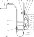
- the Figure 7 shows a tensioning device 1 according to the invention for tensioning a tarpaulin 2 on a lateral boundary 3 of a loading area 4 of a vehicle 5 ( Figures 5 and 6 ) with a tensioning element 6 for generating tension in the tarpaulin 2, the tensioning element 6 being designed to exert a tensile force on the tarpaulin 2 so that the tarpaulin 2 is braced over a large area.
- the clamping device 1 is fixed captive with a fixing element 7 in the area of the lateral delimitation 3 of the loading area 4.
- the tensioning device 1 has a free coupling element 8, which is designed for connection to a coupling connection element 12 of the tarpaulin 2.
- connection point 9 The position of the connection point 9 with respect to the fixing element 7 can be changed by means of the tensioning element 6.
- the change in the position of the connection point 9 ensures a planar tensioning of the cover tarpaulin 2 that can be coupled.
- Coupling arrangement shown coupled has a coupling element 8 and a coupling connection element 12.
- the coupling connection element 12 has a hook-shaped structure 25 which engages with the groove-shaped receptacle 11 of the coupling element 12 by coupling the two elements 8, 12.
- a tensioning of the cover tarpaulin 2 that can be coupled, generated via the connection element 10, can lead to a tilting of the elements 8, 12 when the coupling element 8 is coupled to the coupling connection element 12.
- the coupling element 8 has a grip tab 22 which, when the coupling element 8 is coupled to the coupling connection element 12, rests against a stop surface 28 of the coupling connection element 12.
- This abutment of the grip tab 22 on the stop surface 28 enables a secure transmission of the essentially vertically acting tensile forces introduced by the connecting element 10 via the coupling element 8 and the coupling connection element 12 on the tarpaulin 2.
- a stop element 26 is shown on the coupling connection element 12, which is supported on the vehicle boundary surface 27 in order to prevent the coupling connection element 12 from tilting.
- the essentially horizontally acting tensile forces would, without such a support on the vehicle boundary surface 27 fixed to the vehicle, lead to a tilting of these elements 8, 12 by the lever arm made up of the coupling element 8 and the coupling connection element 12, which is reliably prevented by the stop element 26 by the stop element 26 the coupling connecting element 12 is optimally positioned and supported.
- FIG 8 shows a coupling connection element 12 according to the invention in a detailed view.
- the coupling connection element 12 forms an elongated rail and has a hook-shaped structure 25 which, when coupled to the coupling element 8 ( Figure 7 ) transfers applied forces. Via the fastening eyes 29 in the back surface 24 ( Figure 7 ) of the coupling connection element 12, this can be connected to the tarpaulin 2 ( Figure 7 ) are firmly connected.
- the stop element 26, which is an extension of the back surface 24 ( Figure 7 ) of the coupling connection element 12 represents.
Landscapes
- Engineering & Computer Science (AREA)
- Mechanical Engineering (AREA)
- Connection Of Plates (AREA)
- Tents Or Canopies (AREA)
- Clamps And Clips (AREA)
Description
- Die Erfindung betrifft eine Spanneinrichtung zum Verspannen einer Abdeckplane an einer seitlichen Begrenzung einer Ladefläche eines Fahrzeugs, mit wenigstens einem Spannelement zum Erzeugen einer Spannung in der Abdeckplane, wobei das Spannelement dazu ausgebildet ist, auf die Abdeckplane eine Zugkraft derart auszuüben, dass die Abdeckplane flächig verspannt wird, sowie ein Ladungssicherungssystem mit einer solchen Spanneinrichtung.
- Solche Spanneinrichtungen sind aus
DE 20 2013 005256 U1 ,US 2006/101687 A1 ,US 4 657 062 A undUS 2 465 621 A bekannt. - Beim Transport von Ladungen auf den verschiedensten Verkehrswegen müssen die Ladungen vor Witterungseinflüssen, wie beispielsweise Wind und Regen, geschützt werden. Dies geschieht insbesondere durch die Verwendung von Abdeckungen, wie Planen. Die Abdeckungen bestehen üblicherweise aus einem belastbaren und strapazierfähigen Material. Sie müssen robust sein, eine lange Lebensdauer aufweisen und dazu geeignet sein, die Ladung vor äußeren Einflüssen zu schützen. Neben der Wetterschutzfunktion kommt den Abdeckungen aber auch noch häufig eine Ladungssicherungsfunktion zu. Die Abdeckungen bestehen daher aus einem relativ schweren und steifen Material und lassen sich daher sehr schwer bewegen, verstauen und falten. Eine derartige Ausgestaltung der Abdeckung ist notwendig, da sie gegenüber hohen Fahrtwinden und damit einhergehenden Schlagen oder Flattern beständig sein muss und zudem auch großen Zugspannungen standhalten muss.
- Als eine technische Lösung haben sich speziell für Lastkraftwagen oder Anhänger so genannte Curtain-Sider verbreitet, bei welchen eine Plane über einem auf der Ladefläche angeordneten Rahmen verspannt wird. Die Ladefläche ist meist von einem Dach überdeckt, und die Seiten und gegebenenfalls auch das Heck werden von einer Plane oder mehreren einzelnen Planen abgedeckt. Die Plane kann oft wie ein Vorhang seitlich verschoben werden, muss aber für den Transport fixiert und gesichert werden. Dazu ist es erforderlich, die Plane gleichförmig und mit einer bestimmten Spannung an dem Rahmen bzw. der Ladefläche selbst zu verzurren. Hierbei werden häufig so genannte Übertotpunktspanner eingesetzt, mittels derer innerhalb der Plane verlaufende Spanngurte jeweils einzeln auf eine bestimmte Zugspannung gebracht werden können. Meist sind diese Gurte innerhalb der Plane angeordnet und mit der Plane verschweißt, wenn dies das Material der Plane zulässt. Bei Curtain-Sidern kann es vorkommen, dass sich einzelne Gurte lösen oder aufgrund der Vielzahl an Gurten ein Verspannen einiger Gurte unterbleibt. Ein weiterer Nachteil ist, dass die Übertotpunktspanner seitlich über den Rahmen der Ladefläche überstehen und beim Rangieren abgefahren werden können. Eine Seite einer Ladefläche komplett freizulegen ist zudem zeitlich sehr aufwendig, da hierzu eine Vielzahl an Spannern gelöst werden muss. Bei der Fixierung der Plane ist es aufwendig, jeden einzelnen Gurt mit dem entsprechenden Spanner bzw. der Ladefläche zu verbinden.
- Falls die Übertotpunktspanner nicht zum Einsatz kommen sollen, bietet sich wahlweise ein Verspannen mittels einer Einrichtung an, an welche jeder einzelne der Gurte gekoppelt wird, um dann durch eine Bewegung der Einrichtung ein gemeinsames simultanes Verzurren aller Gurte zu ermöglichen. Hierbei kann ein Verbinden jedes einzelnen Gurtes mit der Einrichtung zum Beispiel dadurch erfolgen, dass an den Gurten jeweils Ösen, Schlaufen oder Augen vorgesehen sind, welche in Haken oder Klemmen oder dergleichen Beschläge eingehakt werden. Die entsprechenden Haken können dann zum Beispiel an einer drehbaren Welle angebracht sein, die entlang des bodenseitigen Ladeflächenrahmens drehbar gelagert ist. Durch Verdrehen der Welle kann die Plane verspannt werden. Aus der
EP 0 753 422 A1 ist eine derartige Spanneinrichtung bekannt. Allerdings ist aufgrund der Vielzahl von Spannern die Fixierung und das Lösen der Abdeckplane zeitaufwendig und die Anordnung der Spannelemente macht eine Fixierung der Abdeckplane kompliziert. - Aufgabe der Erfindung ist es daher, eine Vorrichtung anzugeben, welche die beschriebenen Nachteile behebt eine einfache und schnelle flächige Verspannung der Abdeckplane ermöglicht.
- Gelöst wird diese Aufgabe durch eine Spannvorrichtung mit den Merkmalen des Anspruchs 1, ein Ladungssicherungssystem mit den Merkmalen des Anspruchs 10 und eine Koppelungsanordnung mit den Merkmalen des Anspruchs 12.
- Dadurch dass die Spanneinrichtung mit wenigstens einem Fixierelement im Bereich der seitlichen Begrenzung der Ladefläche unverlierbar fixierbar ist und wenigstens ein freies Kopplungselement zur Verbindung mit der Abdeckplane ausgebildet ist, wobei das Kopplungselement an wenigstens einem Verbindungspunkt über ein Verbindungselement mit dem Spannelement verbunden ist, wobei der Verbindungspunkt durch das Spannelement in seiner Lage gegenüber dem Fixierelement veränderlich ist, so dass durch Veränderung der Lage des Verbindungspunkts eine Verspannung der ankoppelbaren Abdeckplane erfolgt, kann eine einfach zu handhabende Vorrichtung bereitgestellt werden, bei der eine flächige gleichförmige Verspannung der Abdeckplane gewährleistet ist und bei der eine einfache Ankopplung der Abdeckplane möglich ist. Insbesondere ermöglicht das freie Kopplungselement eine einfache und sichere Verbindung zwischen der ankoppelbaren Abdeckplane und der Spanneinrichtung.
- Die erfindungsgemäße Spanneinrichtung ist dazu vorgesehen, eine Abdeckplane, beispielsweise eine Lastkraftwagen-Plane zum Abdecken einer Ladefläche, mittels eines Spannelements zu verspannen, durch Erzeugen einer Spannung in der Abdeckplane, wobei das Spannelement dazu ausgebildet ist, auf die Abdeckplane eine Zugkraft auszuüben. Hierfür kann die Außenkontur des Spannelementes verändert werden. Die Abdeckplane wird zunächst lose gekoppelt. Die Veränderung der Außenkontur bewirkt dann die Erzeugung einer Zugspannung innerhalb der Abdeckplane. Vorteilhafte Ausgestaltungen und Weiterbildungen der Erfindung ergeben sich aus den abhängigen Ansprüchen.
- Gemäß einer vorteilhaften Ausgestaltung der Erfindung ist vorgesehen, dass das Verbindungselement flexibel ausgebildet und an die Kontur des Spannelements anpassbar ist. Diese flexible Ausgestaltung des Verbindungselementes ermöglicht eine besonders gute flächige Verspannung der ankoppelbaren Abdeckplane, da sich das Verbindungselement an die Kontur des Spannelements anpasst. Das Material des Verbindungselementes kann dem der Abdeckplane entsprechen. Bevorzugt ist das Verbindungselement unelastisch, also nicht oder nur wenig dehnbar. Eine Dehnbarkeit des Verbindungselementes ist aber keineswegs ausgeschlossen. So kann das Material des Verbindungselementes etwas dehnbarer als die Abdeckplane sein, wodurch eine aufgebrachte Zugspannung besonders gleichmäßig auf der Abdeckplane verteilt wird.
- Erfindungsgemäß ist vorgesehen, dass das Verbindungelement das Spannelement zumindest teilweise manschettenförmig umgibt. Hierdurch kann das Spannelement durch das Verbindungselement geschützt werden, was die Vorrichtung fehlertoleranter macht.
- Eine bevorzugte Ausführung sieht vor, dass das Verbindungselement als sich zumindest annährend parallel zur seitlichen Begrenzung erstreckender Abschnitt, vorzugsweise aus Planen- oder Textilmaterial, ausgebildet ist. Gerade ein solcher Abschnitt ermöglicht eine besonders gleichmäßige, flächige Verspannung der Abdeckplane.
- Besonders vorteilhaft ist die Weiterbildung, dass das Kopplungselement als sich zumindest annährend parallel zur seitlichen Begrenzung erstreckende Schiene ausgebildet ist, mit nutförmigen Aufnahmen zur Aufnahme von wenigstens einem Kopplungsverbindungselement der Abdeckplane. Eine solche Schiene verringert den Aufwand bei der Kopplung der Abdeckplane mit der Spanneinrichtung. Mit der Verwendung einer Schiene können die Handgriffe bei der Verspannung einer Abdeckplane deutlich reduziert werden. Die Zeit für das Be- und Entladen von Gütern kann hierdurch deutlich verringert werden. Die Verwendung einer entsprechenden Schiene ermöglicht zudem eine gleichförmige Verteilung der Zugkraft, wodurch eine Faltenbildung und ein Flattern der Abdeckplane vermieden werden kann. Die Schiene besteht idealerweise aus einem strapazierfähigen, witterungsbeständigen und/oder formbeständigen Material, bevorzugt einem metallischen Werkstoff. Als idealer Werkstoff hat sich insbesondere Aluminium und Edelstahl herausgestellt, da hierdurch das Gewicht des Lastkraftwagen insgesamt in einem vertretbaren Rahmen gehalten werden kann.
- Weiter vorteilhaft ist die Ausgestaltung, dass an dem Kopplungselement wenigstens ein Reflektor angebracht ist. Ein solcher Reflektor erhöht die Sicherheit im Straßenverkehr deutlich.
- Eine vorteilhafte Ausführungsform der Erfindung sieht vor, dass das Kopplungselement eine im Wesentlichen plane Außenseite aufweist, die im gekoppelten Zustand nach außen, weg von der Fahrzeugmitte zeigt. Eine solche Ausgestaltung wirkt sich insbesondere positiv auf den Kraftstoffverbrauch und den CO2-Ausstoß aus, da die gebräuchlichen Übertotpunktspanner entfallen können und hierdurch eine verbesserte Aerodynamik im Fahrtwind gegeben ist. Durch die plane Außenseite wird zudem eine Verletzungsgefahr, beispielsweise durch ein Hängenbleiben, minimiert.
- Eine vorteilhafte Ausgestaltung sieht vor, dass der Reflektor an der planen Außenseite angebracht ist. Hierdurch ist eine besonders hohe Sichtbarkeit des Reflektors gegeben. Außerdem lässt sich der Reflektor auf der planen Außenseite besonders einfach anbringen.
- Erfindungsgemäß ist vorgesehen, dass das Spannelement reversibel expandierbar ausgebildet ist. Hierdurch ist eine besonders einfache flächige Verspannung der Abdeckplane möglich. Die Abdeckplane wird hierzu zunächst mit der Spanneinrichtung an dem Kopplungselement gekoppelt. Die reversible Expandierung des Spannelements erzeugt dann eine besonders gleichmäßige Zugspannung innerhalb der gekoppelten Abdeckplane. Das expandierbare Spannelement erstreckt sich bevorzugt im Wesentlichen entlang der gesamten Ausdehnung der Spanneinrichtung. Hierdurch kann eine besonders gleichmäßige Zugkraft auf die Abdeckplane erreicht werden, wodurch die Abdeckplane über ihre gesamte Ausdehnung gleichförmig verspannt werden kann. Faltenbildung und flatternde Abdeckplanen die sich negativ auf die Aerodynamik des Lastkraftwagens bzw. des Anhängers auswirken und somit zu einem erhöhten Spritverbrauch führen, werden so vermieden. Das reversibel expandierbare Spannelement kann als Schlauch ausgebildet sein, welcher sich dabei idealerweise über die gesamte Ausdehnung der Spanneinrichtung erstreckt. Denkbar ist aber auch, dass es sich bei dem expandierbaren Spannelement um ein Kissen oder eine Mehrzahl von Kissen handelt.
- Weiter vorteilhaft ist die Ausgestaltung, dass das Spannelement durch Fluidbeaufschlagung, insbesondere durch die Fluidversorgung des Fahrzeugs, expandierbar ist. Eine solche Ausgestaltung bietet auf besonders einfache Art und Weise eine flächige Verspannung der Abdeckplane, da für die Expandierung des Spannelements einfach die Fluidversorgung des Fahrzeugs, insbesondere die Druckluftversorgung, genutzt werden kann. Eine derartige Ausgestaltung bietet zudem den Vorteil, dass der Druck im Spannelement überall gleich groß ist und sich somit eine gleichmäßige Spannung auf die Abdeckplane erzeugen lässt.
- Eine weitere vorteilhafte Ausführungsform der Erfindung sieht vor, dass das Spannelement einen Spannträger mit einem ovalen Querschnitt aufweist, welcher drehbar um die Querschnittsachse und / oder arretierbar ausgebildet ist. Mit einem solchen Spannträger kann auf besonders einfache Art und Weise der Verbindungspunkt in seiner Lage gegenüber dem Fixierelement verändert werden, sodass eine Verspannung der ankoppelbaren Abdeckplane erfolgt.
- Ferner ist Gegenstand der Erfindung ein Ladungssicherungssystem. Das erfindungsgemäße Ladungssicherungssystem weist eine Abdeckplane und eine Spanneinrichtung mit der oben und im Folgenden beschriebenen Ausgestaltungen auf, wobei die Abdeckplane wenigstens ein Kopplungsverbindungselement aufweist, welches dazu ausgebildet ist, mit dem Kopplungselement der Spanneinrichtung verkoppelt zu werden.
- Eine vorteilhafte Ausgestaltung des Ladungssicherungssystems sieht vor, dass das Kopplungsverbindungselement als sich zumindest annährend parallel zur seitlichen Begrenzung erstreckende Schiene ausgebildet ist, welche ein Profil zur Aufnahme des Kopplungselements aufweist. Ein solches Kopplungsverbindungselement verringert den Aufwand bei der Kopplung der Abdeckplane mit der Spanneinrichtung.
- Ferner ist Gegenstand der Erfindung eine Koppelungsanordnung mit wenigstens einem Kopplungselement und wenigstens einem Kopplungsverbindungselement, wobei das Kopplungsverbindungselement wenigstens eine hakenförmige Struktur aufweist und das Kopplungselement wenigstens eine nutförmige Aufnahme zur Kopplung mit wenigstens einer hakenförmigen Struktur aufweist. Eine derartige Kopplungsanordnung ermöglicht eine besonders einfache aber sichere Kopplung eines Kopplungsverbindungselements mit einem Kopplungselement.
- Eine vorteilhafte Ausgestaltung der Koppelungsanordnung sieht vor, dass das Kopplungselement wenigstens eine Grifflasche und das Kopplungsverbindungselement wenigstens eine Anschlagsfläche aufweist, wobei die Grifflasche bei Kopplung des Kopplungselements mit dem Kopplungsverbindungselement an der Anschlagsfläche anliegt. Das Anliegen der Grifflasche an der Anschlagsfläche verhindert auf sehr einfache, aber sichere Art und Weise eine Verkippung des Kopplungselementes gegenüber dem Kopplungverbindungselement. Eine solche Verkippung kann insbesondere auftreten, wenn auf die verkoppelten Elemente eine Kraft, insbesondere eine Zugbelastung durch die Abdeckplane und das Verbindungselement, ausgeübt wird.
- Eine weitere vorteilhafte Ausführungsform der Koppelungsanordnung ist, dass das Kopplungsverbindungselement ein Anschlagselement aufweist, welches dazu ausgebildet ist, eine Abstützung des Kopplungsverbindungselements an einer Fahrzeugbegrenzungsfläche zu gewährleisten. Mit einem solchen Anschlagselement kann eine Verkippung des Kopplungsverbindungselementes einfach aber sicher verhindert werden. Eine solche Verkippung kann insbesondere auftreten, wenn auf das Kopplungsverbindungselement eine Kraft, insbesondere eine Zugbelastung durch die Abdeckplane, ausgeübt wird.
- Weitere Merkmale, Einzelheiten und Vorteile der Erfindung ergeben sich aufgrund der nachfolgenden Beschreibung sowie anhand der Zeichnungen. Ausführungsbeispiele der Erfindung sind in den folgenden Zeichnungen schematisch dargestellt und werden nachfolgend näher beschrieben. Es zeigen:
- Figur 1:
- schematische Schnittansicht auf eine erfindungsgemäße Spanneinrichtung;
- Figur 2:
- schematische Schnittansicht auf ein erfindungsgemäßes Kopplungselement;
- Figur 3:
- schematische Schnittansicht auf eine erfindungsgemäße Spanneinrichtung;
- Figur 4:
- schematische Schnittansicht auf eine erfindungsgemäße Spanneinrichtung im verspannten Zustand;
- Figur 5:
- Heckansicht auf einen Lastkraftwagen oder Anhänger mit einem erfindungsgemäßen Ladungssicherungssystem;
- Figur 6:
- Heckansicht auf einen Lastkraftwagen oder Anhänger mit einem erfindungsgemäßen Ladungssicherungssystem im verspannten Zustand.
- Figur 7:
- schematische Schnittansicht auf eine erfindungsgemäße Spanneinrichtung im verspannten Zustand;
- Figur 8:
- schematische Ansicht auf ein erfindungsgemäßes Kopplungsverbindungselement;
- In den Figuren allgemein mit dem Bezugszeichen 1 bezeichnet ist eine erfindungsgemäße Spanneinrichtung dargestellt. Die Darstellung gemäß
Figur 1 zeigt eine Spanneinrichtung 1 zum Verspannen einer Abdeckplane 2 (Figuren 5 und 6 ) an einer seitlichen Begrenzung 3 (Figuren 5 und 6 ) einer Ladefläche 4 (Figuren 5 und 6 ) eines Fahrzeugs 5 (Figuren 5 und 6 ) mit einem Spannelement 6 zum Erzeugen einer Spannung in der Abdeckplane 2 (Figuren 5 und 6 ), wobei das Spannelement 6 dazu ausgebildet ist, auf die Abdeckplane 2 (Figuren 5 und 6 ) eine Zugkraft auszuüben, so dass die Abdeckplane 2 (Figuren 5 und 6 ) flächig verspannt wird. Die Spanneinrichtung 1 ist mit einem Fixierelement 7 im Bereich der seitlichen Begrenzung 3 (Figuren 5 und 6 ) der 4 Ladefläche (Figuren 5 und 6 ) unverlierbar fixiert. Außerdem weist die Spanneinrichtung 1 ein freies Kopplungselement 8 auf, welches zur Verbindung mit der Abdeckplane 2 (Figur 5 und 6 ) ausgebildet ist. Das Kopplungselement 8 ist an dem Verbindungspunkt 9 über ein Verbindungselement 10 mit dem Spannelement 6 verbunden. Der Verbindungspunkt 9 ist an dem Spannelement 6 gegenüber von dem Fixierelement 7 angeordnet. Mittels des Spannelements 6 kann die Lage des Verbindungspunktes 9 gegenüber dem Fixierelement 7 verändert werden. Die Veränderung der Lage des Verbindungspunktes 9 sorgt für eine flächige Verspannung der ankoppelbaren Abdeckplane 2 (Figur 5 und 6 ). In dem hier dargestellten Ausführungsbeispiel erfolgt die Verspannung mittels eines reversibel expandierbaren Spannelements 6. Um eine Zugkraft auf die Abdeckplane 2 (Figuren 5 und 6 ) zu erzeugen und diese flächig zu verspannen, wird in dem dargestellten Ausführungsbeispiel das Spannelement 6 mit Fluid, vorzugsweise Druckluft, beaufschlagt. Hierdurch wird das Spannelement 6 expandiert und der Verbindungspunkt 9 wird gegenüber dem Fixierelement 7 in seiner Lage verändert. Durch die Verbindung des Verbindungselementes 10 an dem Verbindungspunkt 9 zieht das Verbindungselement 10 an dem Kopplungselement 8 und verspannt eine mit dem Kopplungselement 8 gekoppelte Abdeckplane 2 (Figur 6 ). -
Figur 2 zeigt das Kopplungselement 8 ausFigur 1 detaillierter dargestellt. Es handelt sich bei dieser Darstellung um eine Schnittdarstellung durch eine sich in Blickrichtung erstreckende Schiene. Diese Schiene weist nutförmige Aufnahmen 11 zur Aufnahme von einem Kopplungsverbindungselement 12 (Figur 5 und 6 ) der Abdeckplane 2 (Figur 5 und 6 ) auf. Die nutförmige Aufnahme 11 ist grundsätzlich auf keine bestimmte Form festgelegt. Wesentlich ist nur, dass die Aufnahme 11 so ausgebildet ist, dass sich die Aufnahme 11 zur sicheren Kopplung mit dem Kopplungsverbindungselement 12 (Figuren 5 und 6 ) eignet. Auf der planen Außenseite 14 (Figur 1 ) ist ein Reflektor 13 angebracht. Das Kopplungselement 8 kann formschlüssig mit dem flexiblen Verbindungselement 10 verbunden sein. Hierzu weist das Kopplungselement 8 eine Nut 19 auf, welche sich vorzugsweise entlang der gesamten Schiene erstreckt. Als formschlüssiger Verbindungspartner der Nut 19 weist das flexible Verbindungselement 10 eine Verdickung 20 (Figur 1 ) auf. Die Verdickung 20 kann erfindungsgemäß dadurch erhalten werden, dass ein erster Endabschnitt des Verbindungselementes 10 (Figur 1 ) als Schlaufe ausgebildet ist. In der Schlaufe kann ein rohrförmiges Element 21 angeordnet sein. Um einen besonders guten Formschluss zu erhalten, entspricht eine solch ausgebildete Verdickung 20 im Wesentlichen den Ausmaßen d, b der Nut 19. Außerdem weist das Kopplungselement 8 eine im Winkel α abstehende Grifflasche 22 auf, mit welcher sich das Kopplungselement 8 leicht ergreifen lässt. Hierzu ist außerdem eine Abschrägung 23 vorgesehen, welche die Greifbarkeit zusätzlich erhöht. Das Kopplungselement 8 besteht vorzugsweise aus einem strapazierfähigen, witterungsbeständigen und formbeständigen Material, bevorzugt aus Aluminium. - Die
Figur 3 zeigt eine besonders vorteilhafte Ausführungsform der Spanneinrichtung 1. Die Darstellung gemäßFigur 3 zeigt eine Spanneinrichtung 1 zum Verspannen einer Abdeckplane 2 (Figuren 5 und 6 ) an einer seitlichen Begrenzung 3 (Figuren 5 und 6 ) einer Ladefläche 4 (Figuren 5 und 6 ) eines Fahrzeugs 5 (Figuren 5 und 6 ) mit einem Spannelement 6 zum Erzeugen einer Spannung in der Abdeckplane 2 (Figuren 5 und 6 ), wobei das Spannelement 6 dazu ausgebildet ist, auf die Abdeckplane 2 (Figuren 5 und 6 ) eine Zugkraft auszuüben, so dass die Abdeckplane 2 (Figuren 5 und 6 ) flächig verspannt wird. Die Spanneinrichtung 1 ist mit einem Fixierelement 7 im Bereich der zeitlichen Begrenzung 3 (Figur 5 und 6 ) der 4 Ladefläche (Figur 5 und 6 ) unverlierbar fixiert war. Außerdem weist die Spanneinrichtung 1 ein freies Kopplungselement 8 (siehe auchFigur 2 ) auf, welches zur Verbindung mit der Abdeckplane 2 (Figur 5 und 6 ) ausgebildet ist. Das Kopplungselement 8 ist an dem Verbindungspunkt 9 über ein Verbindungselement 10 mit dem Spannelement 6 verbunden. Der Verbindungspunkt 9 ist an dem Spannelement 6 gegenüber von dem Fixierelement 7 angeordnet. Mittels des Spannelements 6 kann die Lage des Verbindungspunktes 9 gegenüber dem Fixierelement 7 verändert werden. Die Veränderung der Lage des Verbindungspunktes 9 sorgt für eine flächige Verspannung der ankoppelbaren Abdeckplane 2 (Figur 5 und 6 ). Bei der hier dargestellten Ausführungsform weist das Spannelement 6 einen Spannträger 16 mit einem ovalen Querschnitt auf. Dieser Spannträger 16 ist drehbar um eine Querschnittsachse 17 in Blickrichtung ausgebildet. Durch Verdrehung des Spannträgers 16 kann die Lage des Verbindungspunktes 9 gegenüber dem Fixierelement 7 verändert werden um eine Verspannung der ankoppelbaren Abdeckplane 2 (Figur 5 und 6 ) herzustellen. Eine Arretierungsmöglichkeit (nicht dargestellt) des Spannträgers 16 stellt sicher, dass die Abdeckplane 2 (Figuren 5 und 6 ) sicher durch das Spannelement 6 verspannt ist und bleibt. - In
Figur 4 ist eine Spanneinrichtung 1 gemäßFigur 3 im verspannten Zustand zu sehen. Der Spannträger ist hier arretiert und die Lage des Verbindungspunktes 9 gegenüber dem Fixierelement 7 ist derart verändert, dass eine an das Kopplungselement 8 gekoppelte Abdeckplane (Figur 6 ) verspannt sein würde. - Die
Figur 5 zeigt eine schematische Heckansicht auf einen Lastkraftwagen 5 oder Anhänger 5 mit einem erfindungsgemäßen Ladungssicherungssystem 18. Das Ladungssicherungssystem 18 umfasst eine Abdeckplane 2 und eine Spanneinrichtung 1, wie sie bereits oben und im Folgenden beschrieben ist. Die Abdeckplane 2 weist ein Kopplungsverbindungselement 12 auf, welches dazu ausgebildet ist, mit dem Kopplungselement 8 der Spanneinrichtung 1 verkoppelt zu werden. Das Kopplungsverbindungselement 12 ist bevorzugt als Winkelprofil ausgebildet und weist dabei einen flächigen Grundkörper und einen Vorsprung auf. Der Vorsprung dient dazu mit der nutförmigen Aufnahme 11 (Figur 2 ) des Kopplungselementes 8 in Eingriff zu kommen und ist vorteilhafter Weise als abgewinkeltes Profil ausgebildet. Der flächige Grundkörper ist mit der Abdeckplane 2 verbunden. Die erfindungsgemäße Spanneinrichtung 1 ist in einem montierten Zustand bevorzugt an einer seitlichen Begrenzung 3 einer Ladefläche 4 eines Fahrzeugs 5 mit dem Fixierelement 7 fixiert. Idealerweise ist die Spanneinrichtung 1 unterhalb der Ladefläche 4 angeordnet. Steht die Spanneinrichtung 1 nicht mit der Abdeckplane 2 in Verbindung, wie inFigur 6 dargestellt, dann weist eine derartige Anordnung den Vorteil auf, dass die Spanneinrichtung 1 beim Be- und Entladen des Fahrzeugs nicht stört. Die Spanneinrichtung 1 befindet sich in diesem Fall aufgrund der Schwerkraft und ihrer Anordnung innerhalb und unterhalb des Fahrzeugrahmens bzw. der Ladefläche 4. -
Figur 6 zeigt eine Heckansicht auf einen stark vereinfachten Lastkraftwagen 5 oder Anhänger 5 gemäßFigur 5 mit einem erfindungsgemäßen Ladungssicherungssystem 18 in einem verspannten Zustand. Ist das Spannelement 6 (Figur 1 und4 ) gespannt, dann wird eine Spannung in vertikaler Richtung (siehe gestrichelten Pfeil inFigur 6 ), d.h. nach unten ziehend, aufgebaut und verspannt die gekoppelte Abdeckplane 2 flächig. - Die
Figur 7 zeigt eine erfindungsgemäße Spanneinrichtung 1 zum Verspannen einer Abdeckplane 2 an einer seitlichen Begrenzung 3 einer Ladefläche 4 eines Fahrzeugs 5 (Figur 5 und 6 ) mit einem Spannelement 6 zum Erzeugen einer Spannung in der Abdeckplane 2, wobei das Spannelement 6 dazu ausgebildet ist, auf die Abdeckplane 2 eine Zugkraft auszuüben, so dass die Abdeckplane 2 flächig verspannt wird. Die Spanneinrichtung 1 ist mit einem Fixierelement 7 im Bereich der seitlichen Begrenzung 3 der Ladefläche 4 unverlierbar fixiert. Außerdem weist die Spanneinrichtung 1 ein freies Kopplungselement 8 auf, welches zur Verbindung mit einem Kopplungsverbindungselement 12 der Abdeckplane 2 ausgebildet ist. Mittels des Spannelements 6 kann die Lage des Verbindungspunktes 9 gegenüber dem Fixierelement 7 verändert werden. Die Veränderung der Lage des Verbindungspunktes 9 sorgt für eine flächige Verspannung der ankoppelbaren Abdeckplane 2. Durch die Verbindung des Verbindungselementes 10 an dem Verbindungspunkt 9 zieht das Verbindungselement 10 an dem Kopplungselement 8, welches mit dem Kopplungsverbindungselement 12 der Abdeckplane 2 verbunden ist, wodurch die so gekoppelte Abdeckplane 2 verspannt wird. - Die in
Figur 7 verkoppelt dargestellte Kopplungsanordnung weist ein Kopplungselement 8 und ein Kopplungsverbindungselement 12 auf. Das Kopplungsverbindungselement 12 hat eine hakenförmige Struktur 25 die mit der nutförmigen Aufnahme 11 des Kopplungselement 12 durch die Verkopplung der beiden Element 8, 12 in Eingriff kommt. Eine über das Verbindungselement 10 erzeugte Verspannung der ankoppelbaren Abdeckplane 2 kann bei Verkopplung des Kopplungselement 8 mit dem Kopplungsverbindungselement 12 zu einer Verkippung der Elemente 8, 12 führen. Um dies zu verhindern weist das Kopplungselement 8 eine Grifflasche 22 auf, die bei Kopplung des Kopplungselementes 8 mit dem Kopplungsverbindungselement 12 an einer Anschlagsfläche 28 des Kopplungsverbindungselements 12 anliegt. Dieses Anliegen der Grifflasche 22 an der Anschlagsfläche 28 ermöglicht eine sichere Übertragung der durch das Verbindungselement 10 eingebrachten, im Wesentlichen vertikal wirkenden, Zugkräfte über das Kopplungselement 8 und das Kopplungsverbindungselement 12 auf die Abdeckplane 2. Zudem ist ein Anschlagselement 26 an dem Kopplungsverbindungselement 12 gezeigt, welches an der Fahrzeugbegrenzungsfläche 27 abgestützt ist, um eine Verkippung des Kopplungsverbindungselements 12 zu verhindern. Die im Wesentlichen horizontal wirkenden Zugkräfte würden, ohne eine solche Abstützung an der fahrzeugfesten Fahrzeugbegrenzungsfläche 27, durch den Hebelarm aus Kopplungselement 8 und Kopplungsverbindungselement 12 zu einer Verkippung dieser Elemente 8, 12 führen, was durch das Anschlagselement 26 sicher verhindert wird, indem das Anschlagselement 26 das Kopplungsverbindungselements 12 optimal positioniert und abstützt. -
Figur 8 zeigt ein erfindungsgemäßes Kopplungsverbindungselement 12 in einer Detailansicht. Das Kopplungsverbindungselement 12 bildet eine sich länglich erstreckende Schiene und weist eine hakenförmige Struktur 25 auf, die bei Verkopplung mit dem Kopplungselement 8 (Figur 7 ) aufgebrachte Kräfte überträgt. Über die Befestigungsösen 29 in der Rückenfläche 24 (Figur 7 ) des Kopplungsverbindungselements 12 kann dieses mit der Abdeckplane 2 (Figur 7 ) fest verbunden werden. Gut zu erkennen ist auch das Anschlagselement 26, welches eine Verlängerung der Rückenfläche 24 (Figur 7 ) des Kopplungsverbindungselements 12 darstellt. -
- 1
- Spanneinrichtung
- 2
- Abdeckplane
- 3
- seitlichen Begrenzung
- 4
- Ladefläche
- 5
- Fahrzeugs
- 6
- Spannelement
- 7
- Fixierelement
- 8
- freies Kopplungselement
- 9
- Verbindungspunkt
- 10
- Verbindungselement
- 11
- Aufnahmenuten
- 12
- Kopplungsverbindungselement
- 13
- Reflektor
- 14
- plane Außenseite
- 15
- Fahrzeugmitte
- 16
- Spannträger
- 17
- Querschnittsachse
- 18
- Ladungssicherungssystem
- 19
- Nut
- 20
- Verdickung
- 21
- rohrförmiges Element
- 22
- Grifflasche
- 23
- Abschrägung
- 24
- Rückenfläche
- 25
- hakenförmige Struktur
- 26
- Anschlagselement
- 27
- Fahrzeugbegrenzungsfläche
- 28
- Anschlagsfläche
- 29
- Befestigungsösen
Claims (14)
- Spanneinrichtung (1) zum Verspannen einer Abdeckplane (2) an einer seitlichen Begrenzung (3) einer Ladefläche (4) eines Fahrzeugs (5), mit wenigstens einem Spannelement (6) zum Erzeugen einer Spannung in der Abdeckplane (2), wobei das Spannelement (6) dazu ausgebildet ist, auf die Abdeckplane (2) eine Zugkraft derart auszuüben, dass die Abdeckplane (2) flächig verspannt wird, wobei die Spanneinrichtung (1) mit wenigstens einem Fixierelement (7) im Bereich der seitlichen Begrenzung (3) der Ladefläche (4) unverlierbar fixierbar ist und wenigstens ein freies Kopplungselement (8) zur Verbindung mit der Abdeckplane (2) ausgebildet ist, wobei das Kopplungselement (8) an wenigstens einem Verbindungspunkt (9) über ein Verbindungselement (10) mit dem Spannelement (6) verbunden ist, wobei der Verbindungspunkt (9) durch das Spannelement (6) in seiner Lage gegenüber dem Fixierelement (7) veränderlich ist, so dass durch Veränderung der Lage des Verbindungspunkts (9) eine Verspannung der ankoppelbaren Abdeckplane (2) erfolgt,
dadurch gekennzeichnet, dass das Verbindungelement (10) das Spannelement (6) zumindest teilweise manschettenförmig umgibt, wobei das Spannelement (6) reversibel expandierbar ausgebildet ist. - Spanneinrichtung nach Anspruch 12, dadurch gekennzeichnet, dass das Verbindungselement (10) flexibel ausgebildet und an die Kontur des Spannelements anpassbar ist.
- Spanneinrichtung nach Anspruch 1 oder 2, dadurch gekennzeichnet, dass das Verbindungselement (10) als sich zumindest annährend parallel zur seitlichen Begrenzung (3) erstreckender Abschnitt, vorzugsweise aus Planen- oder Textilmaterial, ausgebildet ist.
- Spanneinrichtung nach einem der Ansprüche 1 bis 3, dadurch gekennzeichnet, dass das Kopplungselement (8) als sich zumindest annährend parallel zur seitlichen Begrenzung (3) erstreckende Schiene ausgebildet ist, mit nutförmigen Aufnahmen (11) zur Aufnahme von wenigstens einem Kopplungsverbindungselement (12) der Abdeckplane (2).
- Spanneinrichtung nach einem der Ansprüche 1 bis 4, dadurch gekennzeichnet, dass an dem Kopplungselement (8) wenigstens ein Reflektor (13) angebracht ist.
- Spanneinrichtung nach einem der Ansprüche 1 bis 5, dadurch gekennzeichnet, dass das Kopplungselement (8) eine im Wesentlichen plane Außenseite (14) aufweist, die im gekoppelten Zustand nach außen, weg von der Fahrzeugmitte (15) zeigt.
- Spanneinrichtung nach Anspruch 5 und 6, dadurch gekennzeichnet, dass der Reflektor (13) an der planen Außenseite (14) angebracht ist.
- Spanneinrichtung nach einem der Ansprüche 1 bis 7, dadurch gekennzeichnet, dass das Spannelement (6) durch Fluidbeaufschlagung, insbesondere durch die Fluidversorgung des Fahrzeugs (5), expandierbar ist.
- Spanneinrichtung nach einem der Ansprüche 1 bis 7, dadurch gekennzeichnet, dass das Spannelement (6) einen Spannträger (16) mit einem ovalen Querschnitt aufweist, welcher drehbar um die Querschnittsachse (17) und / oder arretierbar ausgebildet ist.
- Ladungssicherungssystem (18) für ein Fahrzeug (5), mit einer Abdeckplane (2) und mit einer Spanneinrichtung (1) nach einem der Ansprüche 1 bis 9, wobei die Abdeckplane (2) wenigstens ein Kopplungsverbindungselement (12) aufweist, welches dazu ausgebildet ist, mit dem Kopplungselement (8) der Spanneinrichtung (1) verkoppelt zu werden.
- Ladungssicherungssystem nach Anspruch 10, dadurch gekennzeichnet, dass das Kopplungsverbindungselement (12) als sich zumindest annährend parallel zur seitlichen Begrenzung (3) erstreckende Schiene ausgebildet ist, welche ein Profil zur Aufnahme des Kopplungselements (8) aufweist.
- Koppelungsanordnung für ein Fahrzeug (5), mit einer Spanneinrichtung nach einem der Ansprüche 1 bis 9 oder mit einem Ladungssicherungssystem (18) nach einem der Ansprüche 10 bis 11, mit wenigstens einem Kopplungselement (8) und wenigstens einem Kopplungsverbindungselement (12), wobei das Kopplungsverbindungselement (12) wenigstens eine hakenförmige Struktur (25) aufweist und das Kopplungselement (8) wenigstens eine nutförmige Aufnahme (11) zur Kopplung mit wenigstens einer hakenförmigen Struktur (25) aufweist.
- Koppelungsanordnung nach Anspruch 12, dadurch gekennzeichnet, dass das Kopplungselement (8) wenigstens eine Grifflasche (22) und das Kopplungsverbindungselement (12) wenigstens eine Anschlagsfläche (28) aufweist, wobei die Grifflasche (22) bei Kopplung des Kopplungselements (8) mit dem Kopplungsverbindungselement (12) an der Anschlagsfläche (28) anliegt.
- Koppelungsanordnung nach Anspruch 12 oder 13, dadurch gekennzeichnet, dass das Kopplungsverbindungselement (12) ein Anschlagselement (26) aufweist, welches dazu ausgebildet ist, eine Abstützung des Kopplungsverbindungselements (12) an einer Fahrzeugbegrenzungsfläche (27) zu gewährleisten.
Priority Applications (1)
| Application Number | Priority Date | Filing Date | Title |
|---|---|---|---|
| PL17780631T PL3512726T3 (pl) | 2016-09-16 | 2017-09-15 | Układ napinający i system zabezpieczenia ładunku |
Applications Claiming Priority (2)
| Application Number | Priority Date | Filing Date | Title |
|---|---|---|---|
| DE202016105188.6U DE202016105188U1 (de) | 2016-09-16 | 2016-09-16 | Spanneinrichtung und Ladungssicherungssystem |
| PCT/EP2017/073296 WO2018050829A1 (de) | 2016-09-16 | 2017-09-15 | Spanneinrichtung und ladungssicherungssystem |
Publications (3)
| Publication Number | Publication Date |
|---|---|
| EP3512726A1 EP3512726A1 (de) | 2019-07-24 |
| EP3512726B1 true EP3512726B1 (de) | 2021-11-17 |
| EP3512726B9 EP3512726B9 (de) | 2022-03-02 |
Family
ID=57536996
Family Applications (1)
| Application Number | Title | Priority Date | Filing Date |
|---|---|---|---|
| EP17780631.2A Active EP3512726B9 (de) | 2016-09-16 | 2017-09-15 | Spanneinrichtung und ladungssicherungssystem |
Country Status (4)
| Country | Link |
|---|---|
| EP (1) | EP3512726B9 (de) |
| DE (1) | DE202016105188U1 (de) |
| PL (1) | PL3512726T3 (de) |
| WO (1) | WO2018050829A1 (de) |
Families Citing this family (1)
| Publication number | Priority date | Publication date | Assignee | Title |
|---|---|---|---|---|
| DE102024139808B3 (de) * | 2024-12-27 | 2025-10-23 | Alexander Bayer | Befestigungssystem mit einem keder |
Family Cites Families (7)
| Publication number | Priority date | Publication date | Assignee | Title |
|---|---|---|---|---|
| US2465621A (en) * | 1946-05-27 | 1949-03-29 | Harrison S Wheeler | Tarpaulin anchor |
| US4657062A (en) * | 1985-03-08 | 1987-04-14 | Tuerk Robert P | Roll tarp locking assembly |
| EP0753422B1 (de) | 1995-07-14 | 1999-09-15 | Vicente Miro Bravo | Luftdichte Abdichtung und Spannvorrichtung für isothermische Vorhänge von Kühlfahrzeugen |
| DE10341899A1 (de) * | 2002-09-11 | 2004-04-22 | Roland International B.V. | Spannvorrichtung für wenigstens eine Plane eines Verdecks |
| US6988713B2 (en) * | 2003-11-25 | 2006-01-24 | Walls Eric L | Adjustable latch plate for open-top vehicle |
| US7500325B2 (en) * | 2004-11-15 | 2009-03-10 | Michael Wayne Pulliam | Apparatus and method for retaining and selectively tensioning a sheet material display to a billboard |
| DE202013005256U1 (de) * | 2013-06-11 | 2013-07-26 | Fahrzeugbau Karl Tang Gmbh | Abdeckplanensystem zurn Spannen einer LKW-Plane |
-
2016
- 2016-09-16 DE DE202016105188.6U patent/DE202016105188U1/de not_active Expired - Lifetime
-
2017
- 2017-09-15 WO PCT/EP2017/073296 patent/WO2018050829A1/de not_active Ceased
- 2017-09-15 PL PL17780631T patent/PL3512726T3/pl unknown
- 2017-09-15 EP EP17780631.2A patent/EP3512726B9/de active Active
Non-Patent Citations (1)
| Title |
|---|
| None * |
Also Published As
| Publication number | Publication date |
|---|---|
| WO2018050829A1 (de) | 2018-03-22 |
| PL3512726T3 (pl) | 2022-03-21 |
| EP3512726B9 (de) | 2022-03-02 |
| EP3512726A1 (de) | 2019-07-24 |
| DE202016105188U1 (de) | 2016-11-22 |
Similar Documents
| Publication | Publication Date | Title |
|---|---|---|
| DE19619642C1 (de) | Schutzvorrichtung für Kombifahrzeuge | |
| DE202008016326U1 (de) | Vorrichtung zur Sicherung von Ladung | |
| DE19634104C1 (de) | Netz zur Lagesicherung von Ladegut auf Ladeflächen von Fahrzeugen | |
| EP2420406B1 (de) | Vorrichtung zum Sichern von Ladung auf einer Ladefläche eines Fahrzeugaufbaus | |
| EP3512726B1 (de) | Spanneinrichtung und ladungssicherungssystem | |
| DE60220940T2 (de) | Ladungsstützvorrichtung | |
| EP2371594A2 (de) | Fahrzeugaufbau mit Seitenplane inbesondere für Nutzfahrzeuge | |
| DE102020134925B3 (de) | Plane und Nutzfahrzeug mit einer solchen Plane | |
| EP3015311B2 (de) | Nutzfahrzeugaufbau und Verfahren zum Sichern der Lage eines Transportguts auf einer Ladefläche eines Nutzfahrzeugs | |
| DE102019101047B4 (de) | Nutzfahrzeugaufbau und Nutzfahrzeug mit einem derartigen Nutzfahrzeugaufbau | |
| EP3243700B1 (de) | Nutzfahrzeugaufbau | |
| EP3243678A1 (de) | Nutzfahrzeugaufbau | |
| EP3666567A1 (de) | Begrenzungsplane für einen nutzfahrzeugaufbau, nutzfahrzeugaufbau und nutzfahrzeug mit einem nutzfahrzeugaufbau | |
| DE10114409B4 (de) | Einrichtung und Verfahren zum Befestigen eines Transportguts auf der Ladefläche eines Transportfahrzeugs | |
| EP3546260B1 (de) | Planenverschlusselement, plane und fahrzeugaufbau | |
| DE102004021173B3 (de) | Transportsicherung für Kraftwagen | |
| DE202013005256U1 (de) | Abdeckplanensystem zurn Spannen einer LKW-Plane | |
| EP3599147A1 (de) | Aufbau eines nutzfahrzeugs mit einem der rückwand zugeordneten spoilerelement | |
| EP4290034A1 (de) | Zelt | |
| EP4331913A1 (de) | Teleskopierbare ladungssicherungsrunge | |
| DE3027117A1 (de) | Aus einer zugmaschine und einem sattelanhaenger bestehender sattelzug | |
| DE102020006329A1 (de) | Aufbau eines Nutzfahrzeugs mit Schiebeverdeck | |
| DE20306124U1 (de) | Vorrichtung zur Ladungssicherung | |
| EP4488117A1 (de) | Nutzfahrzeugaufbau mit ladungssicherungseinrichtung und verfahren zur ladungssicherung | |
| EP2662229A2 (de) | Einrichtung zum Spannen einer LKW-Plane |
Legal Events
| Date | Code | Title | Description |
|---|---|---|---|
| STAA | Information on the status of an ep patent application or granted ep patent |
Free format text: STATUS: UNKNOWN |
|
| STAA | Information on the status of an ep patent application or granted ep patent |
Free format text: STATUS: THE INTERNATIONAL PUBLICATION HAS BEEN MADE |
|
| PUAI | Public reference made under article 153(3) epc to a published international application that has entered the european phase |
Free format text: ORIGINAL CODE: 0009012 |
|
| STAA | Information on the status of an ep patent application or granted ep patent |
Free format text: STATUS: REQUEST FOR EXAMINATION WAS MADE |
|
| 17P | Request for examination filed |
Effective date: 20190416 |
|
| AK | Designated contracting states |
Kind code of ref document: A1 Designated state(s): AL AT BE BG CH CY CZ DE DK EE ES FI FR GB GR HR HU IE IS IT LI LT LU LV MC MK MT NL NO PL PT RO RS SE SI SK SM TR |
|
| AX | Request for extension of the european patent |
Extension state: BA ME |
|
| DAV | Request for validation of the european patent (deleted) | ||
| DAX | Request for extension of the european patent (deleted) | ||
| GRAP | Despatch of communication of intention to grant a patent |
Free format text: ORIGINAL CODE: EPIDOSNIGR1 |
|
| STAA | Information on the status of an ep patent application or granted ep patent |
Free format text: STATUS: GRANT OF PATENT IS INTENDED |
|
| INTG | Intention to grant announced |
Effective date: 20201214 |
|
| GRAJ | Information related to disapproval of communication of intention to grant by the applicant or resumption of examination proceedings by the epo deleted |
Free format text: ORIGINAL CODE: EPIDOSDIGR1 |
|
| STAA | Information on the status of an ep patent application or granted ep patent |
Free format text: STATUS: REQUEST FOR EXAMINATION WAS MADE |
|
| INTC | Intention to grant announced (deleted) | ||
| GRAP | Despatch of communication of intention to grant a patent |
Free format text: ORIGINAL CODE: EPIDOSNIGR1 |
|
| STAA | Information on the status of an ep patent application or granted ep patent |
Free format text: STATUS: GRANT OF PATENT IS INTENDED |
|
| INTG | Intention to grant announced |
Effective date: 20210601 |
|
| GRAS | Grant fee paid |
Free format text: ORIGINAL CODE: EPIDOSNIGR3 |
|
| GRAA | (expected) grant |
Free format text: ORIGINAL CODE: 0009210 |
|
| STAA | Information on the status of an ep patent application or granted ep patent |
Free format text: STATUS: THE PATENT HAS BEEN GRANTED |
|
| AK | Designated contracting states |
Kind code of ref document: B1 Designated state(s): AL AT BE BG CH CY CZ DE DK EE ES FI FR GB GR HR HU IE IS IT LI LT LU LV MC MK MT NL NO PL PT RO RS SE SI SK SM TR |
|
| REG | Reference to a national code |
Ref country code: GB Ref legal event code: FG4D Free format text: NOT ENGLISH |
|
| REG | Reference to a national code |
Ref country code: DE Ref legal event code: R096 Ref document number: 502017012056 Country of ref document: DE |
|
| REG | Reference to a national code |
Ref country code: IE Ref legal event code: FG4D Free format text: LANGUAGE OF EP DOCUMENT: GERMAN |
|
| REG | Reference to a national code |
Ref country code: AT Ref legal event code: REF Ref document number: 1447759 Country of ref document: AT Kind code of ref document: T Effective date: 20211215 |
|
| REG | Reference to a national code |
Ref country code: CH Ref legal event code: PK Free format text: BERICHTIGUNG B9 |
|
| REG | Reference to a national code |
Ref country code: NL Ref legal event code: FP |
|
| REG | Reference to a national code |
Ref country code: LT Ref legal event code: MG9D |
|
| PG25 | Lapsed in a contracting state [announced via postgrant information from national office to epo] |
Ref country code: RS Free format text: LAPSE BECAUSE OF FAILURE TO SUBMIT A TRANSLATION OF THE DESCRIPTION OR TO PAY THE FEE WITHIN THE PRESCRIBED TIME-LIMIT Effective date: 20211117 Ref country code: LT Free format text: LAPSE BECAUSE OF FAILURE TO SUBMIT A TRANSLATION OF THE DESCRIPTION OR TO PAY THE FEE WITHIN THE PRESCRIBED TIME-LIMIT Effective date: 20211117 Ref country code: FI Free format text: LAPSE BECAUSE OF FAILURE TO SUBMIT A TRANSLATION OF THE DESCRIPTION OR TO PAY THE FEE WITHIN THE PRESCRIBED TIME-LIMIT Effective date: 20211117 Ref country code: BG Free format text: LAPSE BECAUSE OF FAILURE TO SUBMIT A TRANSLATION OF THE DESCRIPTION OR TO PAY THE FEE WITHIN THE PRESCRIBED TIME-LIMIT Effective date: 20220217 |
|
| PG25 | Lapsed in a contracting state [announced via postgrant information from national office to epo] |
Ref country code: IS Free format text: LAPSE BECAUSE OF FAILURE TO SUBMIT A TRANSLATION OF THE DESCRIPTION OR TO PAY THE FEE WITHIN THE PRESCRIBED TIME-LIMIT Effective date: 20220317 Ref country code: SK Free format text: LAPSE BECAUSE OF FAILURE TO SUBMIT A TRANSLATION OF THE DESCRIPTION OR TO PAY THE FEE WITHIN THE PRESCRIBED TIME-LIMIT Effective date: 20211117 Ref country code: SE Free format text: LAPSE BECAUSE OF FAILURE TO SUBMIT A TRANSLATION OF THE DESCRIPTION OR TO PAY THE FEE WITHIN THE PRESCRIBED TIME-LIMIT Effective date: 20211117 Ref country code: PT Free format text: LAPSE BECAUSE OF FAILURE TO SUBMIT A TRANSLATION OF THE DESCRIPTION OR TO PAY THE FEE WITHIN THE PRESCRIBED TIME-LIMIT Effective date: 20220317 Ref country code: NO Free format text: LAPSE BECAUSE OF FAILURE TO SUBMIT A TRANSLATION OF THE DESCRIPTION OR TO PAY THE FEE WITHIN THE PRESCRIBED TIME-LIMIT Effective date: 20220217 Ref country code: LV Free format text: LAPSE BECAUSE OF FAILURE TO SUBMIT A TRANSLATION OF THE DESCRIPTION OR TO PAY THE FEE WITHIN THE PRESCRIBED TIME-LIMIT Effective date: 20211117 Ref country code: HR Free format text: LAPSE BECAUSE OF FAILURE TO SUBMIT A TRANSLATION OF THE DESCRIPTION OR TO PAY THE FEE WITHIN THE PRESCRIBED TIME-LIMIT Effective date: 20211117 Ref country code: GR Free format text: LAPSE BECAUSE OF FAILURE TO SUBMIT A TRANSLATION OF THE DESCRIPTION OR TO PAY THE FEE WITHIN THE PRESCRIBED TIME-LIMIT Effective date: 20220218 Ref country code: ES Free format text: LAPSE BECAUSE OF FAILURE TO SUBMIT A TRANSLATION OF THE DESCRIPTION OR TO PAY THE FEE WITHIN THE PRESCRIBED TIME-LIMIT Effective date: 20211117 |
|
| PG25 | Lapsed in a contracting state [announced via postgrant information from national office to epo] |
Ref country code: SM Free format text: LAPSE BECAUSE OF FAILURE TO SUBMIT A TRANSLATION OF THE DESCRIPTION OR TO PAY THE FEE WITHIN THE PRESCRIBED TIME-LIMIT Effective date: 20211117 Ref country code: RO Free format text: LAPSE BECAUSE OF FAILURE TO SUBMIT A TRANSLATION OF THE DESCRIPTION OR TO PAY THE FEE WITHIN THE PRESCRIBED TIME-LIMIT Effective date: 20211117 Ref country code: EE Free format text: LAPSE BECAUSE OF FAILURE TO SUBMIT A TRANSLATION OF THE DESCRIPTION OR TO PAY THE FEE WITHIN THE PRESCRIBED TIME-LIMIT Effective date: 20211117 Ref country code: DK Free format text: LAPSE BECAUSE OF FAILURE TO SUBMIT A TRANSLATION OF THE DESCRIPTION OR TO PAY THE FEE WITHIN THE PRESCRIBED TIME-LIMIT Effective date: 20211117 |
|
| REG | Reference to a national code |
Ref country code: DE Ref legal event code: R097 Ref document number: 502017012056 Country of ref document: DE |
|
| PLBE | No opposition filed within time limit |
Free format text: ORIGINAL CODE: 0009261 |
|
| STAA | Information on the status of an ep patent application or granted ep patent |
Free format text: STATUS: NO OPPOSITION FILED WITHIN TIME LIMIT |
|
| 26N | No opposition filed |
Effective date: 20220818 |
|
| PG25 | Lapsed in a contracting state [announced via postgrant information from national office to epo] |
Ref country code: AL Free format text: LAPSE BECAUSE OF FAILURE TO SUBMIT A TRANSLATION OF THE DESCRIPTION OR TO PAY THE FEE WITHIN THE PRESCRIBED TIME-LIMIT Effective date: 20211117 |
|
| PG25 | Lapsed in a contracting state [announced via postgrant information from national office to epo] |
Ref country code: SI Free format text: LAPSE BECAUSE OF FAILURE TO SUBMIT A TRANSLATION OF THE DESCRIPTION OR TO PAY THE FEE WITHIN THE PRESCRIBED TIME-LIMIT Effective date: 20211117 |
|
| PG25 | Lapsed in a contracting state [announced via postgrant information from national office to epo] |
Ref country code: MC Free format text: LAPSE BECAUSE OF FAILURE TO SUBMIT A TRANSLATION OF THE DESCRIPTION OR TO PAY THE FEE WITHIN THE PRESCRIBED TIME-LIMIT Effective date: 20211117 |
|
| P01 | Opt-out of the competence of the unified patent court (upc) registered |
Effective date: 20230523 |
|
| PG25 | Lapsed in a contracting state [announced via postgrant information from national office to epo] |
Ref country code: LU Free format text: LAPSE BECAUSE OF NON-PAYMENT OF DUE FEES Effective date: 20220915 |
|
| PG25 | Lapsed in a contracting state [announced via postgrant information from national office to epo] |
Ref country code: IE Free format text: LAPSE BECAUSE OF NON-PAYMENT OF DUE FEES Effective date: 20220915 |
|
| PG25 | Lapsed in a contracting state [announced via postgrant information from national office to epo] |
Ref country code: HU Free format text: LAPSE BECAUSE OF FAILURE TO SUBMIT A TRANSLATION OF THE DESCRIPTION OR TO PAY THE FEE WITHIN THE PRESCRIBED TIME-LIMIT; INVALID AB INITIO Effective date: 20170915 |
|
| PG25 | Lapsed in a contracting state [announced via postgrant information from national office to epo] |
Ref country code: CY Free format text: LAPSE BECAUSE OF FAILURE TO SUBMIT A TRANSLATION OF THE DESCRIPTION OR TO PAY THE FEE WITHIN THE PRESCRIBED TIME-LIMIT Effective date: 20211117 |
|
| PG25 | Lapsed in a contracting state [announced via postgrant information from national office to epo] |
Ref country code: MK Free format text: LAPSE BECAUSE OF FAILURE TO SUBMIT A TRANSLATION OF THE DESCRIPTION OR TO PAY THE FEE WITHIN THE PRESCRIBED TIME-LIMIT Effective date: 20211117 |
|
| PG25 | Lapsed in a contracting state [announced via postgrant information from national office to epo] |
Ref country code: MT Free format text: LAPSE BECAUSE OF FAILURE TO SUBMIT A TRANSLATION OF THE DESCRIPTION OR TO PAY THE FEE WITHIN THE PRESCRIBED TIME-LIMIT Effective date: 20211117 |
|
| REG | Reference to a national code |
Ref country code: CH Ref legal event code: U11 Free format text: ST27 STATUS EVENT CODE: U-0-0-U10-U11 (AS PROVIDED BY THE NATIONAL OFFICE) Effective date: 20251001 |
|
| PGFP | Annual fee paid to national office [announced via postgrant information from national office to epo] |
Ref country code: DE Payment date: 20250919 Year of fee payment: 9 |
|
| PGFP | Annual fee paid to national office [announced via postgrant information from national office to epo] |
Ref country code: NL Payment date: 20250918 Year of fee payment: 9 Ref country code: PL Payment date: 20250820 Year of fee payment: 9 Ref country code: IT Payment date: 20250923 Year of fee payment: 9 |
|
| PGFP | Annual fee paid to national office [announced via postgrant information from national office to epo] |
Ref country code: BE Payment date: 20250918 Year of fee payment: 9 Ref country code: GB Payment date: 20250919 Year of fee payment: 9 |
|
| PGFP | Annual fee paid to national office [announced via postgrant information from national office to epo] |
Ref country code: FR Payment date: 20250922 Year of fee payment: 9 Ref country code: AT Payment date: 20250919 Year of fee payment: 9 |
|
| PGFP | Annual fee paid to national office [announced via postgrant information from national office to epo] |
Ref country code: CZ Payment date: 20250908 Year of fee payment: 9 |
|
| PG25 | Lapsed in a contracting state [announced via postgrant information from national office to epo] |
Ref country code: TR Free format text: LAPSE BECAUSE OF FAILURE TO SUBMIT A TRANSLATION OF THE DESCRIPTION OR TO PAY THE FEE WITHIN THE PRESCRIBED TIME-LIMIT Effective date: 20211117 |
|
| PGFP | Annual fee paid to national office [announced via postgrant information from national office to epo] |
Ref country code: CH Payment date: 20251001 Year of fee payment: 9 |