EP3512695B1 - Wedge drive and method for producing a wedge drive having optimized guidance - Google Patents
Wedge drive and method for producing a wedge drive having optimized guidance Download PDFInfo
- Publication number
- EP3512695B1 EP3512695B1 EP18700907.1A EP18700907A EP3512695B1 EP 3512695 B1 EP3512695 B1 EP 3512695B1 EP 18700907 A EP18700907 A EP 18700907A EP 3512695 B1 EP3512695 B1 EP 3512695B1
- Authority
- EP
- European Patent Office
- Prior art keywords
- sliding
- wedge drive
- side sliding
- guide
- sliding plates
- Prior art date
- Legal status (The legal status is an assumption and is not a legal conclusion. Google has not performed a legal analysis and makes no representation as to the accuracy of the status listed.)
- Active
Links
- 238000004519 manufacturing process Methods 0.000 title claims description 8
- 238000000034 method Methods 0.000 claims description 4
- 239000011248 coating agent Substances 0.000 claims description 2
- 238000000576 coating method Methods 0.000 claims description 2
- 239000000314 lubricant Substances 0.000 claims description 2
- 238000003825 pressing Methods 0.000 claims description 2
- 239000000243 solution Substances 0.000 description 9
- 230000015572 biosynthetic process Effects 0.000 description 7
- 230000007704 transition Effects 0.000 description 4
- 230000006978 adaptation Effects 0.000 description 2
- 230000000694 effects Effects 0.000 description 2
- 239000002184 metal Substances 0.000 description 2
- 238000004080 punching Methods 0.000 description 2
- 238000006243 chemical reaction Methods 0.000 description 1
- 238000005520 cutting process Methods 0.000 description 1
- 238000011161 development Methods 0.000 description 1
- 230000018109 developmental process Effects 0.000 description 1
- 239000000463 material Substances 0.000 description 1
- 239000007787 solid Substances 0.000 description 1
Images


Classifications
-
- B—PERFORMING OPERATIONS; TRANSPORTING
- B21—MECHANICAL METAL-WORKING WITHOUT ESSENTIALLY REMOVING MATERIAL; PUNCHING METAL
- B21D—WORKING OR PROCESSING OF SHEET METAL OR METAL TUBES, RODS OR PROFILES WITHOUT ESSENTIALLY REMOVING MATERIAL; PUNCHING METAL
- B21D19/00—Flanging or other edge treatment, e.g. of tubes
- B21D19/08—Flanging or other edge treatment, e.g. of tubes by single or successive action of pressing tools, e.g. vice jaws
- B21D19/082—Flanging or other edge treatment, e.g. of tubes by single or successive action of pressing tools, e.g. vice jaws for making negative angles
- B21D19/084—Flanging or other edge treatment, e.g. of tubes by single or successive action of pressing tools, e.g. vice jaws for making negative angles with linear cams, e.g. aerial cams
-
- B—PERFORMING OPERATIONS; TRANSPORTING
- B30—PRESSES
- B30B—PRESSES IN GENERAL
- B30B1/00—Presses, using a press ram, characterised by the features of the drive therefor, pressure being transmitted directly, or through simple thrust or tension members only, to the press ram or platen
- B30B1/40—Presses, using a press ram, characterised by the features of the drive therefor, pressure being transmitted directly, or through simple thrust or tension members only, to the press ram or platen by wedge means
-
- B—PERFORMING OPERATIONS; TRANSPORTING
- B21—MECHANICAL METAL-WORKING WITHOUT ESSENTIALLY REMOVING MATERIAL; PUNCHING METAL
- B21D—WORKING OR PROCESSING OF SHEET METAL OR METAL TUBES, RODS OR PROFILES WITHOUT ESSENTIALLY REMOVING MATERIAL; PUNCHING METAL
- B21D28/00—Shaping by press-cutting; Perforating
- B21D28/02—Punching blanks or articles with or without obtaining scrap; Notching
- B21D28/20—Applications of drives for reducing noise or wear
-
- B—PERFORMING OPERATIONS; TRANSPORTING
- B21—MECHANICAL METAL-WORKING WITHOUT ESSENTIALLY REMOVING MATERIAL; PUNCHING METAL
- B21D—WORKING OR PROCESSING OF SHEET METAL OR METAL TUBES, RODS OR PROFILES WITHOUT ESSENTIALLY REMOVING MATERIAL; PUNCHING METAL
- B21D28/00—Shaping by press-cutting; Perforating
- B21D28/24—Perforating, i.e. punching holes
- B21D28/32—Perforating, i.e. punching holes in other articles of special shape
- B21D28/325—Perforating, i.e. punching holes in other articles of special shape using cam or wedge mechanisms, e.g. aerial cams
-
- B—PERFORMING OPERATIONS; TRANSPORTING
- B23—MACHINE TOOLS; METAL-WORKING NOT OTHERWISE PROVIDED FOR
- B23Q—DETAILS, COMPONENTS, OR ACCESSORIES FOR MACHINE TOOLS, e.g. ARRANGEMENTS FOR COPYING OR CONTROLLING; MACHINE TOOLS IN GENERAL CHARACTERISED BY THE CONSTRUCTION OF PARTICULAR DETAILS OR COMPONENTS; COMBINATIONS OR ASSOCIATIONS OF METAL-WORKING MACHINES, NOT DIRECTED TO A PARTICULAR RESULT
- B23Q3/00—Devices holding, supporting, or positioning work or tools, of a kind normally removable from the machine
- B23Q3/02—Devices holding, supporting, or positioning work or tools, of a kind normally removable from the machine for mounting on a work-table, tool-slide, or analogous part
- B23Q3/10—Auxiliary devices, e.g. bolsters, extension members
- B23Q3/103—Constructional elements used for constructing work holders
-
- F—MECHANICAL ENGINEERING; LIGHTING; HEATING; WEAPONS; BLASTING
- F16—ENGINEERING ELEMENTS AND UNITS; GENERAL MEASURES FOR PRODUCING AND MAINTAINING EFFECTIVE FUNCTIONING OF MACHINES OR INSTALLATIONS; THERMAL INSULATION IN GENERAL
- F16H—GEARING
- F16H25/00—Gearings comprising primarily only cams, cam-followers and screw-and-nut mechanisms
- F16H25/18—Gearings comprising primarily only cams, cam-followers and screw-and-nut mechanisms for conveying or interconverting oscillating or reciprocating motions
- F16H25/183—Gearings comprising primarily only cams, cam-followers and screw-and-nut mechanisms for conveying or interconverting oscillating or reciprocating motions conveying only reciprocating motion, e.g. wedges
Description
Die vorliegende Erfindung betrifft einen Keiltrieb sowie Verfahren zur Herstellung eines Keiltriebs zur Umlenkung einer vertikalen Pressenkraft in eine horizontale, vorzugsweise lineare Arbeitsbewegung gemäß Ansprüchen 1 und 11.The present invention relates to a wedge drive and a method for producing a wedge drive for redirecting a vertical press force into a horizontal, preferably linear working movement according to
Keiltriebe werden typischerweise in Werkzeugen bei Umformprozessen eingesetzt, in denen Bauteile oder Materialien unter hohem Kraftaufwand umgeformt werden müssen und dabei eine hohe Präzision erforderlich ist.Wedge drives are typically used in tools in forming processes in which components or materials have to be formed with great effort and a high level of precision is required.
Keiltriebe werden z. B. in der Automobilindustrie zur Fertigung von Karosseriebauteilen eingesetzt, insbesondere zur Bearbeitung von großen Blechteilen, beim Zuschnitt, dem Stanzen oder Lochen oder beim Verformen von solchen Blechteilen. Die dabei auftretenden Kräfte erreichen auch Werte deutlich oberhalb von 1000 kN. Eine grundsätzliche Herausforderung besteht bei Keiltrieben darin, dass die Führungen insbesondere die Umsetzung in eine Linearbewegung auch tatsächlich gemäß dem gewünschten präzisen Bewegungsprofil erfolgt.V-drives are z. B. used in the automotive industry for the production of body components, especially for processing large sheet metal parts, when cutting, punching or punching or when deforming such sheet metal parts. The The forces that occur reach values well above 1000 kN. A fundamental challenge with wedge drives is that the guides, in particular the conversion into a linear movement, actually takes place according to the desired precise movement profile.
Gattungsgemäße Keiltriebe sind so ausgebildet, dass diese Führungselemente, Gleitleisten, ein Treiberelement, ein Schieberelement sowie eine positionsfeste Schieberelementaufnahme umfassen, wobei die vertikale Presskraft von der Schieberelementaufnahme aufgenommen wird.Generic wedge drives are designed in such a way that they include guide elements, slide strips, a driver element, a slide element and a position-fixed slide element receptacle, the vertical pressing force being absorbed by the slide element receptacle.
Die Treiberführung dient einer linearen Führung des Schieberelements entlang des Treiberelements. Die Führungseinrichtung dient der linearen Führung des Schieberelements entlang der Schieberelementaufnahme in einer Gleitrichtung.The driver guide serves to guide the slide element linearly along the driver element. The guide device serves to linearly guide the slide element along the slide element receptacle in a sliding direction.
In einer Presse wird die Schieberelementaufnahme, die mit dem beweglichen Pressenelement verbunden ist, in vertikaler Richtung bewegt, wohingegen das Treiberelement positionsfest ist. Durch die Relativbewegung wird eine lineare Bewegung erzeugt. Diese Bewegung soll aber auch bei hohen Kräften möglichst exakt sein, vor allen Dingen, wenn Querkräfte auf den Keiltrieb wirken.In a press, the slide element receptacle, which is connected to the movable press element, is moved in the vertical direction, whereas the driver element is fixed in position. The relative movement creates a linear movement. However, this movement should be as precise as possible even with high forces, especially when transverse forces act on the wedge drive.
In der
Problematisch ist bei der dort gezeigten Lösung die Abstimmung des Führungsspiels zwischen den beiden Gleitleisten und dem zentralen T-Block. Grundsätzlich ist das Einschleifen der Bauteilhöhe der Gleitleisten für die Schieber-Bauhöhe nachteilig, da dort eben eine Primärfläche durch Umfansgschleifen eingeschliffen wird. Hierzu wird exemplarisch auf die
In der genannten
Ein weiterer Keilschieber, bei welchem zusätzliche individuell anpassbare Gleitplatten vorgesehen sind, ist aus der
Es ist daher Aufgabe der vorliegenden Erfindung eine alternative Lösung vorzusehen, mit der die Querkräfte optimiert abgefangen bzw. aufgenommen werden können und bei der die Herstellung und Anpassung der Gleitleisten einfach und kostengünstig möglich ist.It is therefore the object of the present invention to provide an alternative solution with which the transverse forces can be absorbed or absorbed in an optimized manner and in which the production and adaptation of the sliding strips is simple and cost-effective.
Diese Aufgabe wird durch die Merkmalskombination gemäß Anspruch 1 gelöst.This task is solved by the combination of features according to
Der Grundgedanke der vorliegenden Erfindung liegt darin, eine spezifische Gleitplattenformation vorzusehen. Ein weiterer Aspekt betrifft das Einstellen des Führungsspiels zwischen den Seitengleitplatten und der Mittenführung der vorgeschlagenen Gleitplattenformation bei der Herstellung oder Montage eines Keiltriebs.The basic idea of the present invention is to provide a specific sliding plate formation. Another aspect relates to adjusting the guide play between the side sliding plates and the center guide of the proposed sliding plate formation when manufacturing or assembling a wedge drive.
Zwischen dem Treiberelement und Schieberelementaufnahme ist das Schieberelement angeordnet. Das Schieberelement und die Schieberelementaufnahme stellen zwei Führungselemente dar, an denen eine Führungseinrichtung mit einer Gleitplattenanordnung mit zwei Seitengleitplatten und einer Mittenführung angeordnet ist.The slide element is arranged between the driver element and the slide element receptacle. The slide element and the slide element receptacle represent two guide elements on which a guide device with a sliding plate arrangement with two side sliding plates and a central guide is arranged.
Die Seitengleitplatten sind an einem der beiden Führungselemente (Schieberelement oder Schieberelementaufnahme) befestigt und in einer Querrichtung, die senkrecht auf der Gleitrichtung steht, zueinander beabstandet. Die Mittenführung ist zwischen den beiden Seitengleitplatten angeordnet.The side sliding plates are attached to one of the two guide elements (slider element or slider element holder) and are spaced apart from one another in a transverse direction that is perpendicular to the sliding direction. The center guide is arranged between the two side sliding plates.
Erfindungsgemäß ist nun eine wenigstens einmal geschulterte Ausgestaltung der Seitengleitplatten vorgesehen. Eine korrespondierende Stufe ist in der Anlagefläche am entsprechenden Führungselement vorgesehen, so dass wenigstens zwei in der Querrichtung voneinander beabstandete Stufen im Führungselement vorgesehen sind.According to the invention, a shouldered design of the side sliding plates is now provided at least once. A corresponding step is provided in the contact surface on the corresponding guide element, so that at least two steps spaced apart from one another in the transverse direction are provided in the guide element.
Die beiden Seitengleitplatten liegen an jeweils einer der beiden Stufen mit ihrer Schulter formschlüssig an, wobei der Formschluss entweder in oder entgegen der definierten Querrichtung wirkt.The two side sliding plates rest on one of the two steps with their shoulder in a form-fitting manner, with the form-fitting acting either in or against the defined transverse direction.
Erfindungsgemäß ist somit ein Keiltrieb gemäß den Merkmalen des Anspruchs 1 vorgesehen, der ausgebildet ist zur Umlenkung einer vertikalen Pressenkraft in eine horizontale, lineare Arbeitsbewegung, mit einem Schieberelement und einer Schieberelementaufnahme, welche zwei Führungselemente darstellen, an denen eine Führungseinrichtung mit einer Gleitplattenanordnung mit zwei Seitengleitplatten und einer Mittenführung angeordnet ist, wobei die Seitengleitplatten in einer Querrichtung Y, die senkrecht auf der Gleitrichtung X steht, zueinander beabstandet sind, wobei die Mittenführung zwischen den beiden Seitengleitplatten angeordnet und an dem Schieberelement befestigt ist, wobei die beiden Seitengleitplatten mit wenigstens einer Schulter ausgebildet sind, die an einer korrespondierenden Stufe ausgebildet am Führungselement mit Formschluss anliegen, wobei der Formschluss in bzw. entgegen der definierten Querrichtung wirkt, so dass Querkräfte abgefangen werden und jede Seitengleitplatte mit wenigstens den folgenden Anlageflächen an der Schieberelementaufnahme anliegt:
- a. je eine Anlagefläche liegt auf einer ersten Ebene E1 und verläuft in Querrichtung Y und
- b. eine Seitenfläche verläuft jeweils senkrecht dazu und liegt der Anlagefläche der Mittenführung vorzugsweise unter Bildung eines definierten Spaltes gegenüber.
- a. One contact surface each lies on a first level E1 and runs in the transverse direction Y and
- b. a side surface runs perpendicular to it and lies opposite the contact surface of the center guide, preferably forming a defined gap.
Eine Anlagefläche der Seitengleitplatte liegt auf einer ersten Ebene und verläuft in Querrichtung. Eine zweite Fläche liegt auf einer Ebene E2, zur ersten Ebene E1 beabstandeten Ebene und verläuft ebenfalls in Querrichtung.A contact surface of the side sliding plate lies on a first level and runs in the transverse direction. A second surface lies on a plane E2, spaced from the first plane E1 Level and also runs in the transverse direction.
Besonders vorteilhaft ist es, wenn die Anlagefläche in Querrichtung betrachtet gleich oder größer ausgebildet ist im Vergleich zur höher liegenden Fläche der Seitengleitplatte.It is particularly advantageous if the contact surface, viewed in the transverse direction, is the same or larger than the higher surface of the side sliding plate.
Die Seitengleitplatte ist über Befestigungsmittel mit der ersten Anlagefläche gegen das entsprechende Führungselement in Formschluss befestigt.The side sliding plate is fastened in a form-fitting manner to the first contact surface against the corresponding guide element via fasteners.
Eine weitere Anlagefläche ist als Übergang zwischen der Anlagefläche und der höher liegenden Fläche und zwar senkrecht oder schräg zu diesen verlaufend ausgebildet. Bei einer schräg verlaufenden Anlagenfläche kann diese mit positiver oder negativer Neigung im Winkel von etwa 70° oder 110° +/- jeweils 10° angebracht sein.Another contact surface is designed as a transition between the contact surface and the higher surface, namely running perpendicularly or obliquely to these. If the system surface is sloping, it can be installed with a positive or negative inclination at an angle of approximately 70° or 110° +/- 10° each.
Alternativ kann der Übergang von der Ebene E1, d. h. der Anlagefläche zur höheren Fläche (Ebene E2) eine rechtwinklige Schulter bzw. Stufe ausbilden.Alternatively, the transition from level E1, i.e. H. form a right-angled shoulder or step between the contact surface and the higher surface (level E2).
Mit Vorteil ist die Ecke der Stufe und/oder Schulter gerundet bzw. mit einem Radius versehen.The corner of the step and/or shoulder is advantageously rounded or provided with a radius.
Mit Vorteil ist eine zusätzliche zweite gegenläufige oder gleichläufige Stufe und Schulter in den jeweiligen Seitengleitplatten und dem korrespondierenden Führungselement ausgebildet. Der Formschluss wird mit Vorteil jedoch nur zwischen den Seitengleitplatten und einer senkrecht zur Querrichtung verlaufenden Anlagefläche zwischen der jeweiligen Seitengleitplatte und dem korrespondierenden Führungselement hergestellt, um den Versuch einer Doppelpassung zu vermeiden.An additional second counter-rotating or co-rotating step and shoulder is advantageously formed in the respective side sliding plates and the corresponding guide element. However, the positive connection is advantageously only produced between the side sliding plates and a contact surface running perpendicular to the transverse direction between the respective side sliding plate and the corresponding guide element in order to avoid attempting a double fit.
Die weitere Alternative ist die Ausbildung einer gegenläufigen Stufe, so dass zwei Anlageflächen auf einer gemeinsamen Ebene liegen und dazwischen eine Anlagefläche auf einer abgestuften Ebene vorgesehen ist, so dass ein Umgriff der beiden Stufen von korrespondierenden Schultern erfolgt.The further alternative is the formation of a counter-rotating step, so that two contact surfaces lie on a common level and a contact surface is provided between them on a stepped level, so that the two steps are encompassed by corresponding shoulders.
Andere vorteilhafte Weiterbildungen der Erfindung sind in den Unteransprüchen gekennzeichnet bzw. werden nachstehend zusammen mit der Beschreibung der bevorzugten Ausführung der Erfindung anhand der Figuren näher dargestellt.Other advantageous developments of the invention are characterized in the subclaims or are shown in more detail below together with the description of the preferred embodiment of the invention with reference to the figures.
Es zeigen:
-
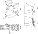
Fig. 1 ein erstes Ausführungsbeispiel eines Keiltriebs; -
Fig. 2 ein zweites Ausführungsbeispiel eines Keiltriebs;, -
Fig. 3 ein drittes Ausführungsbeispiel eines Keiltriebs und -
Fig. 4 ein viertes Ausführungsbeispiel eines Keiltriebs. -
Figuren 5a, 5b, 5c und 5d eine Darstellung der Anpassung einer Gleitplattenformation bei einer herkömmlichen Lösung und -
Figuren 6a, 6b, 6c und 6d eine Darstellung der Anpassung einer Gleitplattenformation bei der erfindungsgemäßen Lösung.
-
Fig. 1 a first embodiment of a wedge drive; -
Fig. 2 a second embodiment of a wedge drive;, -
Fig. 3 a third embodiment of a wedge drive and -
Fig. 4 a fourth embodiment of a wedge drive. -
Figures 5a, 5b, 5c and 5d a representation of the adjustment of a sliding plate formation in a conventional solution and -
Figures 6a, 6b, 6c and 6d a representation of the adaptation of a sliding plate formation in the solution according to the invention.
Im Folgenden wird die Erfindung mit Bezug auf die
In den
Der Keiltrieb 1 ist ausgebildet zur Umlenkung einer vertikalen Pressenkraft in eine horizontale, lineare Arbeitsbewegung und mit einem Schieberelement 2, einem Treiberelement (das nicht dargestellt ist) und einer Schieberelementaufnahme 3. Das Treiberelement ist an dem Schieberelement 2 in herkömmlicher Weise angeordnet.The
Zwischen dem Treiberelement und der Schieberelementaufnahme 3 ist somit das gezeigte Schieberelement 2 angeordnet. Das Schieberelement 2 und die Schieberelementaufnahme 3 stellen zwei Führungselemente 2, 3 dar, an denen eine Führungseinrichtung mit einer Gleitplattenanordnung 10, 20, 30 mit zwei Seitengleitplatten 10, 30 und einer Mittenführung 20 angeordnet ist.The
Die Seitengleitplatten 10, 30 sind an der Schieberelementaufnahme 3 mittels Befestigungsmitteln 5 befestigt und in einer Querrichtung Y, die senkrecht auf der Gleitrichtung X steht, zueinander beabstandet. Die Mittenführung 20 ist zwischen den beiden Seitengleitplatten 10, 30 angeordnet und mittels eines Befestigungsmittels 5 an dem Schieberelement 2 befestigt.The
Die beiden Seitengleitplatten 10, 30 sind mit einer Schulter 11, 31 ausgebildet. Eine korrespondierende Stufe 3a, 3b ist in der Anlagefläche am entsprechenden Führungselement 3 vorgesehen, so dass zwei in der Querrichtung Y voneinander beabstandete Stufen im Führungselement vorgesehen sind.The two
Die beiden Seitengleitplatten 10, 30 liegen an jeweils einer der beiden Stufen 3a, 3b mit ihrer Schulter 11, 31 formschlüssig an, wobei der Formschluss in bzw. entgegen der definierten Querrichtung Y wirkt, so dass Querkräfte abgefangen werden.The two
Jede Seitengleitplatte 10, 30 verfügt über die Flächen 12, 13, 14, bzw. 32, 33, 34.Each
Die erste (außen liegende) Fläche 12 ist eine Anlagefläche 12 der Seitengleitplatte 10 bzw. die erste (außen liegende) Fläche 32 ist eine Anlagefläche 32 der Seitengleitplatte 30. Die Anlageflächen 12, 32 liegen auf einer ersten Ebene E1 und verlaufen in Querrichtung Y. Die Fläche 14 bzw. 34 liegt auf einer zweiten zur ersten Ebene beabstandeten Ebene E2 und verläuft ebenfalls in Querrichtung Y. Die dritte Fläche 13 bzw. 33 verläuft senkrecht dazu.The first (outside)
Die Fläche der Seitengleitplatten 10, 30, welche die jeweils zur Mittelführung 20 zugewandte Seitenfläche 14, 34 ausbildet, bildet auch eine Fläche 15, 35 aus, um ggf. gegen eine korrespondierende Anlagenfläche der Mittenführung 20 anzuliegen, welche ebenfalls in oder bei der Ebene E2 verläuft.The surface of the
Die Anlagefläche 12, 32 in der Ebene E1 ist in Querrichtung Y betrachtet etwas größer d.h. breiter ausgebildet im Vergleich zur Fläche 14, 34 in der Ebene E2 der Seitengleitplatte. Die Anlagefläche 12, 32 erstreckt sich jeweils von der Außenkante A der Seitengleitplatte 10, 30 bis zur senkrechten Seitenfläche 13 bzw. 33. Die Fläche 14, 34 erstreckt sich jeweils von der Seitenfläche 13 bzw. 33 in Richtung zur Mittenführung 20 bis zur Seitenfläche 15 bzw. 35.The
Die weitere Fläche 13, 33 ist jeweils als Übergang zwischen der ersten und zweiten Fläche 12, 14 bzw. 32, 34 und zwar senkrecht zu diesen verlaufend ausgebildet.The
Somit stellt der Übergang von der ersten über die zweite zur dritten Anlagefläche eine Schulter bzw. Stufe dar.The transition from the first to the second to the third contact surface therefore represents a shoulder or step.
In der
In den
In der
Die Abstimmung, erfolgt hier, wie in den
Gemäß der Idee der vorliegenden Erfindung, erfolgt die Anpassung der Gleitplattenformation wie in den
Das Einstellen des Führungsspiels zwischen den Seitengleitplatten 10, 30 und der Mittenführung 20 erfolgt dabei mit den folgenden Schritten:
- a.
Herstellen der Mittenführung 20 nach einem Passmaß; - b. Ermitteln der erforderlichen Gleitleistenhöhe der Gleitleisten im Bereich der Abschnitte G;
- c. Ermitteln des erforderlichen Spaltmaßes zwischen der Gleitleisten 10, 30
zur Mittenführung 20; - d.
Einschleifen der Gleitleisten 10, 30 (und zwar im Bereich G d. h. dieFlächen 14, 34) vorzugsweise durch Umfangsschleifen zum Herstellen der erforderlichen Gleitleistenhöhe und - e. Einschleifen wenigstens einer der Mittenführung zugewandten Seitenflächen 16, 36 vorzugsweise durch Umfangsschleifen bei einer der beiden Gleitleisten 10, 30.
- a. Producing the
center guide 20 according to a fitting size; - b. Determining the required wear strip height of the wear strips in the area of sections G;
- c. Determining the required gap between the sliding
strips center guide 20; - d. Grinding the wear strips 10, 30 (in the area G, ie the
surfaces 14, 34) preferably by circumferential grinding to produce the required wear strip height and - e. Grinding in at least one
side surface slide strips
Die Erfindung beschränkt sich in ihrer Ausführung nicht auf die vorstehend angegebenen bevorzugten Ausführungsbeispiele. Vielmehr ist eine Anzahl von Varianten denkbar, welche von der dargestellten Lösung auch bei grundsätzlich anders gearteten Ausführungen Gebrauch macht. So können die Seitengleitplatten 10, 30 an wenigstens drei Seitenflächen mit einer Verschleißschicht, vorzugsweise als Festschmierstoffflächen oder als Sinterbeschichtung ausgebildet sein.The implementation of the invention is not limited to the preferred exemplary embodiments given above. Rather, a number of variants are conceivable, which make use of the solution presented even in fundamentally different designs. The
Claims (11)
- A wedge drive (1) designed to redirect a vertical pressing force into a horizontal, linear working motion, comprising a sliding element (2) and a sliding element holder (3) which are two guide elements (2, 3) on which a guide device with a sliding plate assembly (10, 20, 30) with two side sliding plates (10, 30) and a central guide (20) is arranged, wherein the side sliding plates (10, 30) are at a distance from one another in the transverse direction (Y) which is perpendicular to the sliding direction (X), wherein the center guide (20) is arranged between the two side sliding plates (10, 20) and is fastened on the sliding element (2), wherein the two side sliding plates (10, 30) are constructed with at least one shoulder (11, 31) which rest(s) with an interlocking connection on a corresponding step (3a, 3b) formed on the guide element (3), wherein the interlocking connection acts in or against the defined transverse direction (Y) so that transverse forces are caught and each side sliding plate (10, 30) rests with at least the following contact surfaces (12, 13, 14 and 32, 33, 34, respectively) on the sliding element holder (3):a. One contact surface (12, 32) of each lies on a first plane (E1) at a distance from the sliding element (2) and runs in the transverse direction (Y), andb. A second contact surface (14, 34) lies on a second plane (E2) at a distance from the first plane (E1) and the sliding element (2) further than the first plane (E1) and also runs in the transverse direction (Y), andc. A third contact surface (13 and 33, respectively) runs perpendicularly to the latter, whereinthe particular side sliding plates (10, 30) are fastened by fastening means (5) to the sliding element holder (3), characterized in that the fastening means (5) are arranged in the area inside the particular first contact surface (12, 32).
- The wedge drive (1) according to Claim 1, wherein a side surface (16 and 36) of each side sliding plate runs perpendicularly or obliquely to the plane (E1) and is opposite the contact surface (21) of the central guide (20).
- The wedge drive (1) according to Claim 1 or 2, wherein the particular side sliding plates (10, 30) are fastened by fastening means (5) to the sliding element holder (3) and the fastening means (5) are arranged in the area inside the contact surface (12, 32).
- The wedge drive (1) according to Claim 1, 2 or 3, wherein a sliding plate section (G) with a surface (14, 34) follows each of the shoulders (11, 31).
- The wedge drive (1) according to Claim 1, characterized in that normally no fastening means (5) for fastening the side sliding plates (10, 30) to the sliding element holder (3) are arranged or provided in the area of the second contact surfaces (14, 34) of the particular side sliding plates (10, 30).
- The wedge drive (1) according to one of the previous claims, characterized in that the contact surfaces (12, 32), viewed in the plane (E1) in the transverse direction (Y), are constructed to be larger in comparison to the second contact surfaces (14, 34) in the area (G), preferably about 1.3 to 1.8 times as large.
- The wedge drive (1) according to one of the previous claims, characterized in that the contact surfaces (12, 32) each extend from the outer edge (A) of the side sliding plates (10, 30) to the perpendicularly running third contact surfaces (13 and 33).
- The wedge drive (1) according to one of the previous claims, characterized in that the contact surfaces (12, 32) each extend from the outer edge (A) of the side sliding plates (10, 30) to the third contact surfaces (13 and 33) running obliquely or transversely to them.
- The wedge drive (1) according to one of the previous claims, characterized in that for the lateral support of each side sliding plate (10, 30), either another step (3a, 3b) is provided on the sliding element holder (3) or another shoulder (11, 31) is provided on the side sliding plate with which an interlocking connection to the sliding element holder (3) takes place.
- The wedge drive (1) according to one of the previous claims, characterized in that the side sliding plates (10, 30) are constructed at at least three side surfaces with an antiwear layer, preferably as fixed lubricant surfaces or as a sintered coating.
- A method for adjusting the guide play between the side sliding plates (10, 30) and the central guide (20) in the production or assembly of a wedge drive (1) according to one of the previous claims with the following steps:a. Production of the center guide (20) after a tolerance on fit;b. Determining the required sliding strip height of the sliding strips in the area of the sections (G);c. Determining the required slot measure between the sliding strips (10, 30) to the central guide (20);d. Grinding the sliding strips (10, 30) for producing the required sliding strip height in the area of the sections (G), namely the second contact surfaces (14, 34), preferably by circumferential grinding; ande. Grinding at least one of the side surfaces (16, 36) facing the central guide, preferably by circumferential grinding at one of the two sliding strips (10, 30).
Applications Claiming Priority (3)
| Application Number | Priority Date | Filing Date | Title |
|---|---|---|---|
| DE202017100989.0U DE202017100989U1 (en) | 2017-02-22 | 2017-02-22 | Wedge drive with optimized guidance |
| DE102017116794.3A DE102017116794B4 (en) | 2017-02-22 | 2017-07-25 | Wedge drive and method for producing a wedge drive with optimized guidance |
| PCT/EP2018/051167 WO2018153578A1 (en) | 2017-02-22 | 2018-01-18 | Wedge drive and method for producing a wedge drive having optimized guidance |
Publications (2)
| Publication Number | Publication Date |
|---|---|
| EP3512695A1 EP3512695A1 (en) | 2019-07-24 |
| EP3512695B1 true EP3512695B1 (en) | 2024-03-06 |
Family
ID=58694258
Family Applications (1)
| Application Number | Title | Priority Date | Filing Date |
|---|---|---|---|
| EP18700907.1A Active EP3512695B1 (en) | 2017-02-22 | 2018-01-18 | Wedge drive and method for producing a wedge drive having optimized guidance |
Country Status (6)
| Country | Link |
|---|---|
| US (1) | US11364530B2 (en) |
| EP (1) | EP3512695B1 (en) |
| KR (1) | KR102406841B1 (en) |
| CN (1) | CN110121411B (en) |
| DE (2) | DE202017100989U1 (en) |
| WO (1) | WO2018153578A1 (en) |
Family Cites Families (13)
| Publication number | Priority date | Publication date | Assignee | Title |
|---|---|---|---|---|
| JPH0786570B2 (en) * | 1987-09-04 | 1995-09-20 | 株式会社ニコン | Light transmitter |
| EP0492014B1 (en) * | 1990-12-28 | 1996-03-20 | Aiko Engineering Co. Ltd. | Automatic grinding apparatus |
| DE102005029140B4 (en) * | 2005-06-23 | 2008-04-03 | Elke Weigelt | Tool fastening device for a wedge drive |
| DE102007045703A1 (en) | 2007-09-24 | 2009-04-09 | Harald Weigelt | Wedge drive with slide holder |
| US8430385B2 (en) * | 2007-09-24 | 2013-04-30 | Harald Weigelt | Wedge drive with slider receiving means |
| KR101139272B1 (en) | 2011-02-16 | 2012-04-26 | 주식회사 루보 | The aerial cam units for with eccentricity-operation prevention means of cam slide |
| DE102012014546A1 (en) * | 2012-07-21 | 2014-01-23 | Strack Norma Gmbh & Co. Kg | cotter |
| ES2684107T3 (en) | 2014-03-06 | 2018-10-01 | Voestalpine Camtec Gmbh | Tool slide |
| CN106103069B (en) * | 2014-03-06 | 2018-08-03 | 奥钢联铸造林茨有限责任公司 | Tool slide mechanism |
| DE102015103114A1 (en) * | 2014-03-06 | 2015-09-10 | Voestalpine Giesserei Linz Gmbh | Improved tool shifter and method for its manufacture |
| DE102014102993B4 (en) | 2014-03-06 | 2016-05-12 | Voestalpine Giesserei Linz Gmbh | tool pusher |
| DE202015106966U1 (en) | 2015-12-21 | 2016-01-28 | Harald Weigelt | cotter |
| HUE055819T2 (en) | 2016-01-25 | 2022-01-28 | Novozymes As | Method to reduce microbial bloom in poultry hatchery |
-
2017
- 2017-02-22 DE DE202017100989.0U patent/DE202017100989U1/en active Active
- 2017-07-25 DE DE102017116794.3A patent/DE102017116794B4/en active Active
-
2018
- 2018-01-18 KR KR1020197019205A patent/KR102406841B1/en active IP Right Grant
- 2018-01-18 CN CN201880005772.0A patent/CN110121411B/en active Active
- 2018-01-18 WO PCT/EP2018/051167 patent/WO2018153578A1/en unknown
- 2018-01-18 US US16/477,338 patent/US11364530B2/en active Active
- 2018-01-18 EP EP18700907.1A patent/EP3512695B1/en active Active
Also Published As
| Publication number | Publication date |
|---|---|
| CN110121411B (en) | 2022-05-24 |
| KR20190120165A (en) | 2019-10-23 |
| DE102017116794B4 (en) | 2024-04-25 |
| CN110121411A (en) | 2019-08-13 |
| DE202017100989U1 (en) | 2017-04-21 |
| KR102406841B1 (en) | 2022-06-10 |
| EP3512695A1 (en) | 2019-07-24 |
| WO2018153578A1 (en) | 2018-08-30 |
| US11364530B2 (en) | 2022-06-21 |
| DE102017116794A1 (en) | 2018-08-23 |
| US20190374990A1 (en) | 2019-12-12 |
Similar Documents
| Publication | Publication Date | Title |
|---|---|---|
| EP3393693B1 (en) | Wedge drive | |
| EP1721770B1 (en) | Guide rail for a motor vehicle sliding roof system | |
| EP3109040A1 (en) | Counter-finish, in particular for forming grooves in paper, cardboard or corrugated cardboard | |
| EP2372172A1 (en) | Device with at least two parts that can be moved relative to each other | |
| EP2383165B1 (en) | Tensioning member for a tensioning device integrated into an adjustable steering column for a motor vehicle | |
| EP3238848B1 (en) | Method for compensating for a production-induced offset in a tool slide | |
| EP3113941B1 (en) | Tool slide | |
| CH710828A2 (en) | Powder press and a chuck housing with preferably more for a Que rpressen movable punches. | |
| DE3506083A1 (en) | STORAGE UNIT | |
| DE102014102993B4 (en) | tool pusher | |
| DE4204841C1 (en) | ||
| EP3512695B1 (en) | Wedge drive and method for producing a wedge drive having optimized guidance | |
| EP4070941B1 (en) | Wedge drive with adjustable working and mounting position | |
| DE2729938C3 (en) | Double belt press for the production of press plates | |
| DD249429A5 (en) | SCHLITTENFUEHRUNGSSYSTEM | |
| DE202023101869U1 (en) | Wedge drive with optimized arrangement of the sliding surfaces | |
| DE2727287C2 (en) | Device for bending profiled panels | |
| EP3095534B1 (en) | Bending machine | |
| EP3996891B1 (en) | Turning device with a centring device | |
| EP1658962A1 (en) | Transfer press | |
| WO2022226563A1 (en) | Milling device for milling out a pocket-shaped recess in a furniture panel for receiving a furniture fitting | |
| DE102019127116A1 (en) | Machine tool with several processing stations | |
| DE102018108015A1 (en) | Rack with collar | |
| EP3587716A1 (en) | Hinge part and hinge provided with at least one said hinge part | |
| DE212017000075U1 (en) | Tool for an electric hand tool |
Legal Events
| Date | Code | Title | Description |
|---|---|---|---|
| STAA | Information on the status of an ep patent application or granted ep patent |
Free format text: STATUS: UNKNOWN |
|
| STAA | Information on the status of an ep patent application or granted ep patent |
Free format text: STATUS: THE INTERNATIONAL PUBLICATION HAS BEEN MADE |
|
| PUAI | Public reference made under article 153(3) epc to a published international application that has entered the european phase |
Free format text: ORIGINAL CODE: 0009012 |
|
| STAA | Information on the status of an ep patent application or granted ep patent |
Free format text: STATUS: REQUEST FOR EXAMINATION WAS MADE |
|
| 17P | Request for examination filed |
Effective date: 20190415 |
|
| AK | Designated contracting states |
Kind code of ref document: A1 Designated state(s): AL AT BE BG CH CY CZ DE DK EE ES FI FR GB GR HR HU IE IS IT LI LT LU LV MC MK MT NL NO PL PT RO RS SE SI SK SM TR |
|
| AX | Request for extension of the european patent |
Extension state: BA ME |
|
| DAV | Request for validation of the european patent (deleted) | ||
| DAX | Request for extension of the european patent (deleted) | ||
| STAA | Information on the status of an ep patent application or granted ep patent |
Free format text: STATUS: EXAMINATION IS IN PROGRESS |
|
| 17Q | First examination report despatched |
Effective date: 20221130 |
|
| RIC1 | Information provided on ipc code assigned before grant |
Ipc: B21D 19/08 20060101ALI20230821BHEP Ipc: B30B 1/40 20060101AFI20230821BHEP |
|
| GRAP | Despatch of communication of intention to grant a patent |
Free format text: ORIGINAL CODE: EPIDOSNIGR1 |
|
| STAA | Information on the status of an ep patent application or granted ep patent |
Free format text: STATUS: GRANT OF PATENT IS INTENDED |
|
| INTG | Intention to grant announced |
Effective date: 20231020 |
|
| GRAS | Grant fee paid |
Free format text: ORIGINAL CODE: EPIDOSNIGR3 |
|
| P01 | Opt-out of the competence of the unified patent court (upc) registered |
Effective date: 20231110 |
|
| GRAA | (expected) grant |
Free format text: ORIGINAL CODE: 0009210 |
|
| STAA | Information on the status of an ep patent application or granted ep patent |
Free format text: STATUS: THE PATENT HAS BEEN GRANTED |
|
| AK | Designated contracting states |
Kind code of ref document: B1 Designated state(s): AL AT BE BG CH CY CZ DE DK EE ES FI FR GB GR HR HU IE IS IT LI LT LU LV MC MK MT NL NO PL PT RO RS SE SI SK SM TR |
|
| REG | Reference to a national code |
Ref country code: GB Ref legal event code: FG4D Free format text: NOT ENGLISH |
|
| REG | Reference to a national code |
Ref country code: DE Ref legal event code: R081 Ref document number: 502018014215 Country of ref document: DE Owner name: F I B R O GMBH, DE Free format text: FORMER OWNER: ANMELDERANGABEN UNKLAR / UNVOLLSTAENDIG, 80297 MUENCHEN, DE |
|
| REG | Reference to a national code |
Ref country code: CH Ref legal event code: EP |
|
| REG | Reference to a national code |
Ref country code: DE Ref legal event code: R096 Ref document number: 502018014215 Country of ref document: DE |
|
| REG | Reference to a national code |
Ref country code: IE Ref legal event code: FG4D Free format text: LANGUAGE OF EP DOCUMENT: GERMAN |