EP3512365B1 - Section de récipient - Google Patents
Section de récipient Download PDFInfo
- Publication number
- EP3512365B1 EP3512365B1 EP17780007.5A EP17780007A EP3512365B1 EP 3512365 B1 EP3512365 B1 EP 3512365B1 EP 17780007 A EP17780007 A EP 17780007A EP 3512365 B1 EP3512365 B1 EP 3512365B1
- Authority
- EP
- European Patent Office
- Prior art keywords
- receptacle section
- configuration
- mouth
- opening
- aerosol
- Prior art date
- Legal status (The legal status is an assumption and is not a legal conclusion. Google has not performed a legal analysis and makes no representation as to the accuracy of the status listed.)
- Active
Links
- 239000000443 aerosol Substances 0.000 claims description 133
- 239000007788 liquid Substances 0.000 claims description 57
- 238000003780 insertion Methods 0.000 claims description 43
- 230000037431 insertion Effects 0.000 claims description 43
- 239000000463 material Substances 0.000 claims description 28
- 238000010438 heat treatment Methods 0.000 claims description 8
- 239000000796 flavoring agent Substances 0.000 description 174
- 235000019634 flavors Nutrition 0.000 description 168
- 235000002637 Nicotiana tabacum Nutrition 0.000 description 37
- 241000208125 Nicotiana Species 0.000 description 36
- 239000000470 constituent Substances 0.000 description 15
- SNICXCGAKADSCV-JTQLQIEISA-N (-)-Nicotine Chemical compound CN1CCC[C@H]1C1=CC=CN=C1 SNICXCGAKADSCV-JTQLQIEISA-N 0.000 description 10
- 229960002715 nicotine Drugs 0.000 description 10
- SNICXCGAKADSCV-UHFFFAOYSA-N nicotine Natural products CN1CCCC1C1=CC=CN=C1 SNICXCGAKADSCV-UHFFFAOYSA-N 0.000 description 10
- 239000000126 substance Substances 0.000 description 10
- 239000002775 capsule Substances 0.000 description 8
- 235000019504 cigarettes Nutrition 0.000 description 7
- 239000011343 solid material Substances 0.000 description 7
- 230000000717 retained effect Effects 0.000 description 6
- 239000012876 carrier material Substances 0.000 description 4
- 239000003571 electronic cigarette Substances 0.000 description 4
- 239000003921 oil Substances 0.000 description 4
- 235000019198 oils Nutrition 0.000 description 4
- PEDCQBHIVMGVHV-UHFFFAOYSA-N Glycerine Chemical compound OCC(O)CO PEDCQBHIVMGVHV-UHFFFAOYSA-N 0.000 description 3
- 150000001875 compounds Chemical class 0.000 description 3
- 239000000203 mixture Substances 0.000 description 3
- 230000000391 smoking effect Effects 0.000 description 3
- 235000019640 taste Nutrition 0.000 description 3
- 235000012550 Pimpinella anisum Nutrition 0.000 description 2
- 240000004760 Pimpinella anisum Species 0.000 description 2
- 229920002301 cellulose acetate Polymers 0.000 description 2
- 239000000084 colloidal system Substances 0.000 description 2
- 239000000284 extract Substances 0.000 description 2
- 230000005484 gravity Effects 0.000 description 2
- 239000002245 particle Substances 0.000 description 2
- 239000004033 plastic Substances 0.000 description 2
- 229920003023 plastic Polymers 0.000 description 2
- 239000000779 smoke Substances 0.000 description 2
- 239000007787 solid Substances 0.000 description 2
- 239000006200 vaporizer Substances 0.000 description 2
- NOOLISFMXDJSKH-UTLUCORTSA-N (+)-Neomenthol Chemical compound CC(C)[C@@H]1CC[C@@H](C)C[C@@H]1O NOOLISFMXDJSKH-UTLUCORTSA-N 0.000 description 1
- WBZFUFAFFUEMEI-UHFFFAOYSA-M Acesulfame k Chemical compound [K+].CC1=CC(=O)[N-]S(=O)(=O)O1 WBZFUFAFFUEMEI-UHFFFAOYSA-M 0.000 description 1
- GUBGYTABKSRVRQ-XLOQQCSPSA-N Alpha-Lactose Chemical compound O[C@@H]1[C@@H](O)[C@@H](O)[C@@H](CO)O[C@H]1O[C@@H]1[C@@H](CO)O[C@H](O)[C@H](O)[C@H]1O GUBGYTABKSRVRQ-XLOQQCSPSA-N 0.000 description 1
- 244000144730 Amygdalus persica Species 0.000 description 1
- 240000007087 Apium graveolens Species 0.000 description 1
- 235000015849 Apium graveolens Dulce Group Nutrition 0.000 description 1
- 235000010591 Appio Nutrition 0.000 description 1
- 108010011485 Aspartame Proteins 0.000 description 1
- 241000167854 Bourreria succulenta Species 0.000 description 1
- 240000007436 Cananga odorata Species 0.000 description 1
- 235000005747 Carum carvi Nutrition 0.000 description 1
- 240000000467 Carum carvi Species 0.000 description 1
- 240000003538 Chamaemelum nobile Species 0.000 description 1
- 235000007866 Chamaemelum nobile Nutrition 0.000 description 1
- 244000037364 Cinnamomum aromaticum Species 0.000 description 1
- 235000014489 Cinnamomum aromaticum Nutrition 0.000 description 1
- 244000223760 Cinnamomum zeylanicum Species 0.000 description 1
- 240000007154 Coffea arabica Species 0.000 description 1
- 235000002787 Coriandrum sativum Nutrition 0.000 description 1
- 244000018436 Coriandrum sativum Species 0.000 description 1
- 229920000742 Cotton Polymers 0.000 description 1
- FBPFZTCFMRRESA-FSIIMWSLSA-N D-Glucitol Natural products OC[C@H](O)[C@H](O)[C@@H](O)[C@H](O)CO FBPFZTCFMRRESA-FSIIMWSLSA-N 0.000 description 1
- FBPFZTCFMRRESA-KVTDHHQDSA-N D-Mannitol Chemical compound OC[C@@H](O)[C@@H](O)[C@H](O)[C@H](O)CO FBPFZTCFMRRESA-KVTDHHQDSA-N 0.000 description 1
- FBPFZTCFMRRESA-JGWLITMVSA-N D-glucitol Chemical compound OC[C@H](O)[C@@H](O)[C@H](O)[C@H](O)CO FBPFZTCFMRRESA-JGWLITMVSA-N 0.000 description 1
- NOOLISFMXDJSKH-UHFFFAOYSA-N DL-menthol Natural products CC(C)C1CCC(C)CC1O NOOLISFMXDJSKH-UHFFFAOYSA-N 0.000 description 1
- 240000002943 Elettaria cardamomum Species 0.000 description 1
- 240000006927 Foeniculum vulgare Species 0.000 description 1
- 235000004204 Foeniculum vulgare Nutrition 0.000 description 1
- 239000005715 Fructose Substances 0.000 description 1
- 229930091371 Fructose Natural products 0.000 description 1
- RFSUNEUAIZKAJO-ARQDHWQXSA-N Fructose Chemical compound OC[C@H]1O[C@](O)(CO)[C@@H](O)[C@@H]1O RFSUNEUAIZKAJO-ARQDHWQXSA-N 0.000 description 1
- 240000001238 Gaultheria procumbens Species 0.000 description 1
- 235000007297 Gaultheria procumbens Nutrition 0.000 description 1
- 241000208152 Geranium Species 0.000 description 1
- WQZGKKKJIJFFOK-GASJEMHNSA-N Glucose Natural products OC[C@H]1OC(O)[C@H](O)[C@@H](O)[C@@H]1O WQZGKKKJIJFFOK-GASJEMHNSA-N 0.000 description 1
- 240000004670 Glycyrrhiza echinata Species 0.000 description 1
- 235000001453 Glycyrrhiza echinata Nutrition 0.000 description 1
- 235000006200 Glycyrrhiza glabra Nutrition 0.000 description 1
- 235000017382 Glycyrrhiza lepidota Nutrition 0.000 description 1
- 244000267823 Hydrangea macrophylla Species 0.000 description 1
- 235000014486 Hydrangea macrophylla Nutrition 0.000 description 1
- 235000010254 Jasminum officinale Nutrition 0.000 description 1
- 240000005385 Jasminum sambac Species 0.000 description 1
- 244000255365 Kaskarillabaum Species 0.000 description 1
- GUBGYTABKSRVRQ-QKKXKWKRSA-N Lactose Natural products OC[C@H]1O[C@@H](O[C@H]2[C@H](O)[C@@H](O)C(O)O[C@@H]2CO)[C@H](O)[C@@H](O)[C@H]1O GUBGYTABKSRVRQ-QKKXKWKRSA-N 0.000 description 1
- 244000165082 Lavanda vera Species 0.000 description 1
- 235000010663 Lavandula angustifolia Nutrition 0.000 description 1
- 235000019501 Lemon oil Nutrition 0.000 description 1
- 241000768444 Magnolia obovata Species 0.000 description 1
- 235000011430 Malus pumila Nutrition 0.000 description 1
- 235000015103 Malus silvestris Nutrition 0.000 description 1
- 229930195725 Mannitol Natural products 0.000 description 1
- 235000007232 Matricaria chamomilla Nutrition 0.000 description 1
- 235000014435 Mentha Nutrition 0.000 description 1
- 241001072983 Mentha Species 0.000 description 1
- 235000006679 Mentha X verticillata Nutrition 0.000 description 1
- 235000016278 Mentha canadensis Nutrition 0.000 description 1
- 244000245214 Mentha canadensis Species 0.000 description 1
- 235000014749 Mentha crispa Nutrition 0.000 description 1
- 244000246386 Mentha pulegium Species 0.000 description 1
- 235000016257 Mentha pulegium Nutrition 0.000 description 1
- 244000078639 Mentha spicata Species 0.000 description 1
- 235000002899 Mentha suaveolens Nutrition 0.000 description 1
- 235000004357 Mentha x piperita Nutrition 0.000 description 1
- 235000001636 Mentha x rotundifolia Nutrition 0.000 description 1
- 244000179970 Monarda didyma Species 0.000 description 1
- 235000010672 Monarda didyma Nutrition 0.000 description 1
- 235000009421 Myristica fragrans Nutrition 0.000 description 1
- 244000270834 Myristica fragrans Species 0.000 description 1
- 235000007265 Myrrhis odorata Nutrition 0.000 description 1
- 244000061176 Nicotiana tabacum Species 0.000 description 1
- 239000004677 Nylon Substances 0.000 description 1
- 235000019502 Orange oil Nutrition 0.000 description 1
- 239000004743 Polypropylene Substances 0.000 description 1
- 235000006040 Prunus persica var persica Nutrition 0.000 description 1
- 229920000297 Rayon Polymers 0.000 description 1
- 240000000513 Santalum album Species 0.000 description 1
- 235000008632 Santalum album Nutrition 0.000 description 1
- 239000004376 Sucralose Substances 0.000 description 1
- 229930006000 Sucrose Natural products 0.000 description 1
- CZMRCDWAGMRECN-UGDNZRGBSA-N Sucrose Chemical compound O[C@H]1[C@H](O)[C@@H](CO)O[C@@]1(CO)O[C@@H]1[C@H](O)[C@@H](O)[C@H](O)[C@@H](CO)O1 CZMRCDWAGMRECN-UGDNZRGBSA-N 0.000 description 1
- 235000016639 Syzygium aromaticum Nutrition 0.000 description 1
- 244000223014 Syzygium aromaticum Species 0.000 description 1
- 235000001484 Trigonella foenum graecum Nutrition 0.000 description 1
- 244000250129 Trigonella foenum graecum Species 0.000 description 1
- 235000009499 Vanilla fragrans Nutrition 0.000 description 1
- 244000263375 Vanilla tahitensis Species 0.000 description 1
- 235000012036 Vanilla tahitensis Nutrition 0.000 description 1
- 235000006886 Zingiber officinale Nutrition 0.000 description 1
- 244000273928 Zingiber officinale Species 0.000 description 1
- 230000002745 absorbent Effects 0.000 description 1
- 239000002250 absorbent Substances 0.000 description 1
- 235000010358 acesulfame potassium Nutrition 0.000 description 1
- 229960004998 acesulfame potassium Drugs 0.000 description 1
- 239000000619 acesulfame-K Substances 0.000 description 1
- 239000012190 activator Substances 0.000 description 1
- 239000000654 additive Substances 0.000 description 1
- 150000001299 aldehydes Chemical class 0.000 description 1
- 239000000605 aspartame Substances 0.000 description 1
- 235000010357 aspartame Nutrition 0.000 description 1
- IAOZJIPTCAWIRG-QWRGUYRKSA-N aspartame Chemical compound OC(=O)C[C@H](N)C(=O)N[C@H](C(=O)OC)CC1=CC=CC=C1 IAOZJIPTCAWIRG-QWRGUYRKSA-N 0.000 description 1
- 229960003438 aspartame Drugs 0.000 description 1
- 230000009286 beneficial effect Effects 0.000 description 1
- 235000021028 berry Nutrition 0.000 description 1
- WQZGKKKJIJFFOK-VFUOTHLCSA-N beta-D-glucose Chemical compound OC[C@H]1O[C@@H](O)[C@H](O)[C@@H](O)[C@@H]1O WQZGKKKJIJFFOK-VFUOTHLCSA-N 0.000 description 1
- WHGYBXFWUBPSRW-FOUAGVGXSA-N beta-cyclodextrin Chemical compound OC[C@H]([C@H]([C@@H]([C@H]1O)O)O[C@H]2O[C@@H]([C@@H](O[C@H]3O[C@H](CO)[C@H]([C@@H]([C@H]3O)O)O[C@H]3O[C@H](CO)[C@H]([C@@H]([C@H]3O)O)O[C@H]3O[C@H](CO)[C@H]([C@@H]([C@H]3O)O)O[C@H]3O[C@H](CO)[C@H]([C@@H]([C@H]3O)O)O3)[C@H](O)[C@H]2O)CO)O[C@@H]1O[C@H]1[C@H](O)[C@@H](O)[C@@H]3O[C@@H]1CO WHGYBXFWUBPSRW-FOUAGVGXSA-N 0.000 description 1
- 235000019658 bitter taste Nutrition 0.000 description 1
- 235000005300 cardamomo Nutrition 0.000 description 1
- 239000000919 ceramic Substances 0.000 description 1
- 229910010293 ceramic material Inorganic materials 0.000 description 1
- 239000003610 charcoal Substances 0.000 description 1
- 239000003795 chemical substances by application Substances 0.000 description 1
- 235000019693 cherries Nutrition 0.000 description 1
- 229930002875 chlorophyll Natural products 0.000 description 1
- 235000019804 chlorophyll Nutrition 0.000 description 1
- ATNHDLDRLWWWCB-AENOIHSZSA-M chlorophyll a Chemical compound C1([C@@H](C(=O)OC)C(=O)C2=C3C)=C2N2C3=CC(C(CC)=C3C)=[N+]4C3=CC3=C(C=C)C(C)=C5N3[Mg-2]42[N+]2=C1[C@@H](CCC(=O)OC\C=C(/C)CCC[C@H](C)CCC[C@H](C)CCCC(C)C)[C@H](C)C2=C5 ATNHDLDRLWWWCB-AENOIHSZSA-M 0.000 description 1
- 235000019506 cigar Nutrition 0.000 description 1
- 235000017803 cinnamon Nutrition 0.000 description 1
- 235000016213 coffee Nutrition 0.000 description 1
- 235000013353 coffee beverage Nutrition 0.000 description 1
- 235000020057 cognac Nutrition 0.000 description 1
- 238000002485 combustion reaction Methods 0.000 description 1
- HCAJEUSONLESMK-UHFFFAOYSA-N cyclohexylsulfamic acid Chemical class OS(=O)(=O)NC1CCCCC1 HCAJEUSONLESMK-UHFFFAOYSA-N 0.000 description 1
- 230000001419 dependent effect Effects 0.000 description 1
- 239000012530 fluid Substances 0.000 description 1
- 235000019264 food flavour enhancer Nutrition 0.000 description 1
- 235000008397 ginger Nutrition 0.000 description 1
- 239000008103 glucose Substances 0.000 description 1
- 235000012907 honey Nutrition 0.000 description 1
- 235000001050 hortel pimenta Nutrition 0.000 description 1
- 239000004615 ingredient Substances 0.000 description 1
- 229910052500 inorganic mineral Inorganic materials 0.000 description 1
- 239000008101 lactose Substances 0.000 description 1
- 239000001102 lavandula vera Substances 0.000 description 1
- 235000018219 lavender Nutrition 0.000 description 1
- 239000010501 lemon oil Substances 0.000 description 1
- 229940010454 licorice Drugs 0.000 description 1
- 239000011344 liquid material Substances 0.000 description 1
- 239000000594 mannitol Substances 0.000 description 1
- 235000010355 mannitol Nutrition 0.000 description 1
- 229940041616 menthol Drugs 0.000 description 1
- 229910052751 metal Inorganic materials 0.000 description 1
- 239000002184 metal Substances 0.000 description 1
- 238000000034 method Methods 0.000 description 1
- OSWPMRLSEDHDFF-UHFFFAOYSA-N methyl salicylate Chemical compound COC(=O)C1=CC=CC=C1O OSWPMRLSEDHDFF-UHFFFAOYSA-N 0.000 description 1
- 239000011707 mineral Substances 0.000 description 1
- 239000001702 nutmeg Substances 0.000 description 1
- 229920001778 nylon Polymers 0.000 description 1
- 239000010502 orange oil Substances 0.000 description 1
- 239000008194 pharmaceutical composition Substances 0.000 description 1
- 229920000728 polyester Polymers 0.000 description 1
- -1 polypropylene Polymers 0.000 description 1
- 229920001155 polypropylene Polymers 0.000 description 1
- 229920001296 polysiloxane Polymers 0.000 description 1
- 239000000843 powder Substances 0.000 description 1
- 235000019719 rose oil Nutrition 0.000 description 1
- 239000010666 rose oil Substances 0.000 description 1
- CVHZOJJKTDOEJC-UHFFFAOYSA-N saccharin Chemical compound C1=CC=C2C(=O)NS(=O)(=O)C2=C1 CVHZOJJKTDOEJC-UHFFFAOYSA-N 0.000 description 1
- 235000002020 sage Nutrition 0.000 description 1
- 239000000600 sorbitol Substances 0.000 description 1
- 241000894007 species Species 0.000 description 1
- 235000019408 sucralose Nutrition 0.000 description 1
- BAQAVOSOZGMPRM-QBMZZYIRSA-N sucralose Chemical compound O[C@@H]1[C@@H](O)[C@@H](Cl)[C@@H](CO)O[C@@H]1O[C@@]1(CCl)[C@@H](O)[C@H](O)[C@@H](CCl)O1 BAQAVOSOZGMPRM-QBMZZYIRSA-N 0.000 description 1
- 239000005720 sucrose Substances 0.000 description 1
- 235000000346 sugar Nutrition 0.000 description 1
- 235000021092 sugar substitutes Nutrition 0.000 description 1
- 150000008163 sugars Chemical class 0.000 description 1
- 239000003765 sweetening agent Substances 0.000 description 1
- 229920002994 synthetic fiber Polymers 0.000 description 1
- 235000019505 tobacco product Nutrition 0.000 description 1
- 235000001019 trigonella foenum-graecum Nutrition 0.000 description 1
- 235000015041 whisky Nutrition 0.000 description 1
- 210000002268 wool Anatomy 0.000 description 1
Images


Classifications
-
- A—HUMAN NECESSITIES
- A24—TOBACCO; CIGARS; CIGARETTES; SIMULATED SMOKING DEVICES; SMOKERS' REQUISITES
- A24F—SMOKERS' REQUISITES; MATCH BOXES; SIMULATED SMOKING DEVICES
- A24F40/00—Electrically operated smoking devices; Component parts thereof; Manufacture thereof; Maintenance or testing thereof; Charging means specially adapted therefor
- A24F40/30—Devices using two or more structurally separated inhalable precursors, e.g. using two liquid precursors in two cartridges
-
- A—HUMAN NECESSITIES
- A24—TOBACCO; CIGARS; CIGARETTES; SIMULATED SMOKING DEVICES; SMOKERS' REQUISITES
- A24F—SMOKERS' REQUISITES; MATCH BOXES; SIMULATED SMOKING DEVICES
- A24F40/00—Electrically operated smoking devices; Component parts thereof; Manufacture thereof; Maintenance or testing thereof; Charging means specially adapted therefor
- A24F40/40—Constructional details, e.g. connection of cartridges and battery parts
- A24F40/42—Cartridges or containers for inhalable precursors
-
- A—HUMAN NECESSITIES
- A24—TOBACCO; CIGARS; CIGARETTES; SIMULATED SMOKING DEVICES; SMOKERS' REQUISITES
- A24B—MANUFACTURE OR PREPARATION OF TOBACCO FOR SMOKING OR CHEWING; TOBACCO; SNUFF
- A24B15/00—Chemical features or treatment of tobacco; Tobacco substitutes, e.g. in liquid form
- A24B15/10—Chemical features of tobacco products or tobacco substitutes
- A24B15/16—Chemical features of tobacco products or tobacco substitutes of tobacco substitutes
- A24B15/167—Chemical features of tobacco products or tobacco substitutes of tobacco substitutes in liquid or vaporisable form, e.g. liquid compositions for electronic cigarettes
-
- A—HUMAN NECESSITIES
- A24—TOBACCO; CIGARS; CIGARETTES; SIMULATED SMOKING DEVICES; SMOKERS' REQUISITES
- A24F—SMOKERS' REQUISITES; MATCH BOXES; SIMULATED SMOKING DEVICES
- A24F40/00—Electrically operated smoking devices; Component parts thereof; Manufacture thereof; Maintenance or testing thereof; Charging means specially adapted therefor
- A24F40/10—Devices using liquid inhalable precursors
-
- A—HUMAN NECESSITIES
- A24—TOBACCO; CIGARS; CIGARETTES; SIMULATED SMOKING DEVICES; SMOKERS' REQUISITES
- A24F—SMOKERS' REQUISITES; MATCH BOXES; SIMULATED SMOKING DEVICES
- A24F40/00—Electrically operated smoking devices; Component parts thereof; Manufacture thereof; Maintenance or testing thereof; Charging means specially adapted therefor
- A24F40/40—Constructional details, e.g. connection of cartridges and battery parts
- A24F40/46—Shape or structure of electric heating means
-
- A—HUMAN NECESSITIES
- A24—TOBACCO; CIGARS; CIGARETTES; SIMULATED SMOKING DEVICES; SMOKERS' REQUISITES
- A24F—SMOKERS' REQUISITES; MATCH BOXES; SIMULATED SMOKING DEVICES
- A24F47/00—Smokers' requisites not otherwise provided for
-
- A—HUMAN NECESSITIES
- A61—MEDICAL OR VETERINARY SCIENCE; HYGIENE
- A61M—DEVICES FOR INTRODUCING MEDIA INTO, OR ONTO, THE BODY; DEVICES FOR TRANSDUCING BODY MEDIA OR FOR TAKING MEDIA FROM THE BODY; DEVICES FOR PRODUCING OR ENDING SLEEP OR STUPOR
- A61M11/00—Sprayers or atomisers specially adapted for therapeutic purposes
- A61M11/04—Sprayers or atomisers specially adapted for therapeutic purposes operated by the vapour pressure of the liquid to be sprayed or atomised
- A61M11/041—Sprayers or atomisers specially adapted for therapeutic purposes operated by the vapour pressure of the liquid to be sprayed or atomised using heaters
- A61M11/042—Sprayers or atomisers specially adapted for therapeutic purposes operated by the vapour pressure of the liquid to be sprayed or atomised using heaters electrical
-
- A—HUMAN NECESSITIES
- A61—MEDICAL OR VETERINARY SCIENCE; HYGIENE
- A61M—DEVICES FOR INTRODUCING MEDIA INTO, OR ONTO, THE BODY; DEVICES FOR TRANSDUCING BODY MEDIA OR FOR TAKING MEDIA FROM THE BODY; DEVICES FOR PRODUCING OR ENDING SLEEP OR STUPOR
- A61M15/00—Inhalators
- A61M15/0028—Inhalators using prepacked dosages, one for each application, e.g. capsules to be perforated or broken-up
-
- A—HUMAN NECESSITIES
- A61—MEDICAL OR VETERINARY SCIENCE; HYGIENE
- A61M—DEVICES FOR INTRODUCING MEDIA INTO, OR ONTO, THE BODY; DEVICES FOR TRANSDUCING BODY MEDIA OR FOR TAKING MEDIA FROM THE BODY; DEVICES FOR PRODUCING OR ENDING SLEEP OR STUPOR
- A61M15/00—Inhalators
- A61M15/06—Inhaling appliances shaped like cigars, cigarettes or pipes
-
- A—HUMAN NECESSITIES
- A24—TOBACCO; CIGARS; CIGARETTES; SIMULATED SMOKING DEVICES; SMOKERS' REQUISITES
- A24F—SMOKERS' REQUISITES; MATCH BOXES; SIMULATED SMOKING DEVICES
- A24F40/00—Electrically operated smoking devices; Component parts thereof; Manufacture thereof; Maintenance or testing thereof; Charging means specially adapted therefor
- A24F40/20—Devices using solid inhalable precursors
-
- A—HUMAN NECESSITIES
- A61—MEDICAL OR VETERINARY SCIENCE; HYGIENE
- A61M—DEVICES FOR INTRODUCING MEDIA INTO, OR ONTO, THE BODY; DEVICES FOR TRANSDUCING BODY MEDIA OR FOR TAKING MEDIA FROM THE BODY; DEVICES FOR PRODUCING OR ENDING SLEEP OR STUPOR
- A61M2205/00—General characteristics of the apparatus
- A61M2205/36—General characteristics of the apparatus related to heating or cooling
- A61M2205/3653—General characteristics of the apparatus related to heating or cooling by Joule effect, i.e. electric resistance
-
- A—HUMAN NECESSITIES
- A61—MEDICAL OR VETERINARY SCIENCE; HYGIENE
- A61M—DEVICES FOR INTRODUCING MEDIA INTO, OR ONTO, THE BODY; DEVICES FOR TRANSDUCING BODY MEDIA OR FOR TAKING MEDIA FROM THE BODY; DEVICES FOR PRODUCING OR ENDING SLEEP OR STUPOR
- A61M2205/00—General characteristics of the apparatus
- A61M2205/82—Internal energy supply devices
- A61M2205/8206—Internal energy supply devices battery-operated
Definitions
- the receptacle section may comprise a third portion for closing off the opening, the third portion being pivotally mounted to the second portion, thereby to allow pivoting of the third portion relative to the second portion, and in the second configuration the third portion may be exposed out of the first portion thereby to allow said pivoting of the third portion, and in the first configuration the third portion may be received in the first portion.
- At least a portion of the second portion may be for receipt into a user's mouth.
- the second portion may be received in the first portion, and the opening of the first portion may be in a side wall of the first portion, and the opening of the second portion may be in a side wall of the second portion, such that in the second configuration the opening of the first portion and the opening of the second portion are aligned with respect to one another to allow insertion and/or removal of said element into and/or from the first portion, through the opening of the first portion and the opening of the second portion, and such that in the first configuration the side wall of the second portion closes off the opening of the first portion.
- At least a portion of the second portion may be for receipt into a user's mouth in use.
- Nicotine may be provided in the liquid 116. Accordingly, where it is intended that the device 100 provides nicotine for the user, the nicotine may be provided in the liquid 116, may be obtained from the flavour element 124, or any combination of these. Likewise, flavourings may be added to the flavour element 124 (whether or not the flavour element 124 is or includes tobacco) and/or to the liquid 116.
- a material of the flavour element 124 may be a solid material, or be a mixture of solid materials, one or more of each comprising one or more constituents that can be mixed with the flow of vapour or aerosol. It will be appreciated that the flavour element 124 may comprise one or more other constituents that are not entrained into the aerosol or vapour passing there through. It will also be appreciated that the flavour element 124 may comprise a portion that does not impart any flavour and/or release any constituents into the flow of a vapour or an aerosol.
- the flavour element 124 may be porous, for example so as allow vapour or aerosol to pass through it.
- the flavour element 124 may be self-supporting, so as to be easily handled by a user (for example easily inserted and/or removed from the mouthpiece 102).
- the flavour element 124 may comprise material wrapped partially or wholly in a wrapper, and/or the flavour element 124 may be supported in a resilient housing, for example a plastic housing (not shown).
- the flavour element may comprise, for example, a flavoured carrier material, such as cellulose acetate or the like.
- the flavour element 124 may be cylindrical, and/or comprise a cylindrical portion, so as to fit easily and/or tightly into a corresponding cylindrical channel 132 of the mouthpiece 102.
- the flavour element 124 comprises a crushable flavour capsule 126 for releasing, when crushed for example by a user, a liquid or a gel that flavours a flow of at least one of a vapour and an aerosol.
- the flavour element 124 may comprise a crushable flavour capsule 126 wrapped or embedded in a suitable carrier material, for example cellulose acetate.
- the carrier material may comprise a material that allows vapour or aerosol to pass there through.
- the carrier material may comprise a material that holds the liquid and/or gel released from the crushable flavour capsule 126 when it is crushed. When the capsule 126 is crushed, the liquid or gel contained therein is released into the material so as to flavour vapour or aerosol passing there through.
- aerosol should be taken as encompassing an aerosol, a vapour or a mixture of an aerosol and vapour.
- the first portion 202a extends a relatively small amount into the channel 232 of the second portion 202a (i.e. the second portion 202a is positioned relatively away from the first portion 202b), such that the remaining (free) length of the channel 232 defined by the second portion 202a is long enough to enable a flavour element 224 be fully received therein (see Figure 2b in particular).
- the first portion 202a extends a relatively large amount into the channel 232 of the second portion 202a (i.e. the second portion 202b is position relatively towards the first portion 202a), such that the remaining (free) length of the channel 232 defined by the second portion is short enough so that a flavour element 224 is not fully receivable therein, and is instead forced to be exposed (protruding) out of the opening 234 of the second portion 202b (see Figure 2c ).
- a user brings a flavour element 224 (which may comprise, for example, an already crushed crushable flavour capsule 226) to the opening 234 of the second portion 202b, and pushes (arrow C) the flavour element 224 into the channel 232 of the second portion 202b so that it is fully received into the channel 232 of the second portion 202b (as shown in Figure 2b ).
- the flavour element 224 is retained in the channel 232 by, at one end, the first portion 202a received in the channel 232 of the second portion 202b, and at the other end by the first lip portion 236.
- the spring 230 causes the second portion 202b to return to the open configuration (see Figure 2d ).
- the first lip portion 236 holds the flavour element 224 partially exposed out of the opening 234, i.e. causes the flavour element 224 to remain protruded out of the opening on the subsequent movement of the second portion 202b away from the first portion 202a.
- the flavour element 224 is therefore presented to a user so that the user can easily and controllably remove the flavour element 224 from the mouth-end section 202.
- the mouth-end section 302 is first in the closed configuration (see Figure 3a ).
- the housing 302b is located relatively away from the body 306 of the overall device 300, and the resilient members 338 are received in the housing 302b.
- the resilient members 338 are thereby restricted from moving radially outwardly by the inner wall of the housing 302b.
- a user may wish to insert, remove, and/or replace a flavour element 324 into and or from the mouth-end section 302.
- a user may cease pushing (or otherwise exerting a force on) the housing 302b towards the body 306 of the device 300, and hence the housing 302b, under the force of the biasing means 330, is forced to slide substantially parallel to the longitudinal axis P-P of the device 300 away from the body 306, back over the resilient members 338 (See Figure 3e ).
- the housing 302b may be pulled or otherwise manipulated away from the body 306 and back over the resilient members 338.
- FIG. 4a to 4d there is illustrated schematically perspective views of a part of an aerosol provision article 400 with another example receptacle section 402 in different configurations.
- the receptacle section 402 is again a mouth-end section 402 of the aerosol provision article 400 although in other examples it may be a receptacle section intermediate of the mouthpiece and the body 406 of the device 400.
- features in Figure 4 and the functioning thereof that are the same or similar to those features already described with reference to Figure 3a to 3e are given similar reference numerals to as in Figures 3a to 3e but increased by 100, and will not be described in detail again.
- the first portion 402a and the second portion 402b are generally elongate and are hollow.
- the first portion 402a extends from the body portion 406 of the device 401 and connects, for example by a screw thread, to the body portion 406.
- the second portion 402b comprises a first part 402b' and a second part 402b" that extends from the first part 402b' and has a slightly narrower diameter than does the first part 402b' and which is slidably received in the first portion 402a.
- the mouth-end section 402 defines a flow channel 432 internally thereof.
- the first part 402b' of the second portion 402b is for receipt into a user's mouth.
- the first part 402b' of the second portion 402b abuts against the first portion 402a and the second part 402b" of the second portion 402b is within the first portion 402a such that the opening 444 in the side wall 442 is closed off by the first portion 402a.
- the first part 402b' of the second portion 402b is relatively distal from the first portion 402a and the second part 402b" of the second portion 402b is exposed so that the opening 444 is exposed for insertion and/or removal of the flavour element 424 there through.
- the mouth-end section 402 of the overall device 400 is initially in a closed configuration (see Figure 4a ).
- a user 440 may wish to insert, remove, or replace a flavour element 424.
- the user 440 pulls on or otherwise manipulates (arrow I) the first part 402b' of the second portion 402b away from the first portion 402a by sliding the second part 402b" of the second portion 402b out of the first portion 402a substantially parallel to the longitudinal axis P-P of the mouth-end section 402 so as to be in the open configuration (as in Figure 4b ).
- the user may then insert (arrow J) the or another flavour element 424, through the now exposed opening 444 in the side wall 442 into the channel 432 (see Figure 4b ).
- the user 440 may push or otherwise manipulate (arrow K in Figure 4c ) the first part 402b" of the second portion 402b back towards the first portion 402a, so that the second part 402b" of the second portion 402b slides substantially parallel to axis P-P of the mouth-end section 402 into the first portion 402a so as to be in the closed configuration (as in Figure 4d ).
- the mouth-end section 502 illustrated in Figures 5a to 5d comprises a first potion 502a, and a second portion 502b slidably mounted to the first portion 502a thereby to allow sliding movement of the second portion 502b relative to the first portion 502a substantially parallel to a longitudinal axis P-P of the mouth-end section 502, between a closed configuration (see Figure 5d ) and an open configuration (see Figure 5a to 5c ).
- the mouth-end section 502 illustrated in Figures 5a to 5d is arranged to allow insertion and/or removal of a flavour element 524 into and/or from the mouth-end section 502 in a direction substantially perpendicular to the longitudinal axis P-P of the mouth-end section 502, through an opening 544 in a side wall 542 of the first portion 502a exposed in the open configuration, into a flow channel.
- the first portion 502a extends from the body portion 506 of the device 501 and connects, for example by a screw thread, to the body portion 506.
- the second portion 502b comprises a first part 502b' and a second part 502b" that extends from the first part 502b' and has a slightly narrower diameter than does the first part 502b' and which is slidably received in the first portion 502a.
- the first part 502b' of the second portion 502b has an outlet 534 for allowing a user to inhale aerosol from the mouth-end section 502.
- the third portion 570 is exposed allowing the third portion 570 to pivot relative to the second part 502b" of the second portion 502b, and hence expose the opening 544 in the side wall 542 of second part 502b" of the second portion 502a for insertion, removal or replacement of a flavour element 542 there through.
- the third portion 570 covers the opening 544 and the second part 502b" of the second portion 502b is inside of the first portion 502a.
- a user 540 may pull or otherwise manipulate (arrow L) the second part 502b" of the second portion 502b away from the first portion 502a, so that the second part 502b" of the second portion 502b slides substantially parallel to the longitudinal axis P-P of the mouth-end section 502 out of the first portion 502a, thereby to expose the second part 502b" of the second portion 502b and the third portion 570 (see Figure 5a ).
- the third portion 570 may then pivot (arrow M) relative to the second part 502b" of the second portion 502b so as to expose the opening 544 in the side wall 542.
- a user may manually push the third portion 507 flush with the side wall 542 of the second portion 502b prior to or while pushing the second portion 502b towards the first portion 502a.
- the mouthpiece 502 is in the closed configuration, and is ready to use (see Figure 5d ).
- the mouth-end section 502 may comprise a retaining element (not shown) that retains the second portion 502b relative to the first portion 502a so that the mouth-end section 502 is retained in the closed configuration unless a significant force (i.e. the force of a user manually pulling on the second portion 502b) is provided.
- FIGS 6a and 6b there is illustrated schematically cross sectional views of a part of an aerosol provision article 600 with another example receptacle section 602 in different configurations.
- the receptacle section 602 is again a mouth-end section 602.
- features in Figure 6 and the functioning thereof that are the same or similar to those features already described with reference to Figure 5a to 5d are given similar reference numerals to as in Figure 5 but increased by 100, and will not be described in detail again.
- the mouth-end section 602 illustrated in Figures 6a and 6b comprises a first potion 602a, and a second portion 602b slidably mounted within the first portion 602a thereby to allow sliding movement of the second portion 602b relative to the first portion 602a substantially parallel to a longitudinal axis P-P of the mouth-end section 602, between a closed configuration (see Figure 6a ) and an open configuration (see Figure 6b ).
- the mouth-end section 602 illustrated in Figures 6a and 6b is arranged to allow insertion and/or removal of a flavour element 624 into and/or from the mouth-end section 602 in a direction substantially perpendicular to the longitudinal axis P-P of the mouth-end section 602, through an opening 644 in a side wall 642 of the second portion 602b exposed in the open configuration, into a channel 632 of the second portion 602b.
- the second portion 602b has an outlet 634 for allowing a user to inhale aerosol from the mouth-end section 602.
- the second portion 602b has a second opening 645 in the side wall 642 of the second portion 602b, the second opening 645 being on an opposite side of the side wall 642 to the opening 644 (now referred to with respect to Figures 6a and 6b as the 'first' opening 644).
- This second opening 645 allows, when the mouth-end section 602 is in the open configuration, for a first flavour element (not shown) to be inserted into the channel 632 of the second portion 602b (e.g. through the first opening 644) whilst simultaneously removing a second flavour 624 installed in the channel 632 element 624 from the channel 632 (e.g. through the second opening 645).
- flavour element 624 This can be achieved, for example, by a user bringing the first flavour element (not shown) up to the first opening 644, and pushing the first flavour element (not shown) laterally against the second flavour element 624, thereby to simultaneously displace the second flavour element 624 from the channel 632 and install the first flavour element (not shown) from the channel 632.
- the mouth-end section 602 therefore allows rapid and convenient flavour element 624 replacement.
- the mouth-end section 602 comprises a connecting means 628 to releasably connect the mouth-end section 602 to a body 606 of the overall device 600.
- the mouth-end section 602 comprises a biasing means 630, (e.g. a spring 630) mounted within the first portion 602a to bias the second portion 602b away from and out of the first portion 602a towards the open configuration (see Figure 6b ).
- the first portion 602a comprises a retaining element 646 to releasably retain the second portion 602b in the first portion 602a such that the mouth-end section 602 is in the closed configuration (see Figure 6a ).
- the retaining element 646 may comprise one or more pins for insertion into corresponding slots (not shown) in the second portion 602b, assembled via a push fit.
- the retaining element 646 may be operable by a user to manually release the second portion 602b from within the first portion 602a.
- the second portion 602b once released, may then automatically slide away from the first portion 602a by action of the biasing means 630 such that the mouth-end section 602 is in the open configuration (see Figure 6b ).
- the flavour element 624 may comprise a crushable flavour capsule 626.
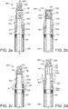
- FIG. 7 there is illustrated schematically a perspective view of a part of an aerosol provision article 700 with another example receptacle section 702 in an open configuration.
- the receptacle section 702 is again a mouth-end section 702.
- features in Figure 7 and the functioning thereof that are the same or similar to those features already described with reference to Figure 6a and 6b are given similar reference numerals to as in Figures 6a and 6b but increased by 100, and will not be described in detail again.
- the mouth-end section 702 illustrated in Figure 7 comprises a first potion 702a, and a second portion 702b slidably mounted to the first portion 702a thereby to allow sliding movement of the second portion 702b relative to the first portion 702a substantially parallel to a longitudinal axis P-P of the mouth-end section 702, between a closed configuration (not shown) and an open configuration (see Figure 7 ).
- the mouth-end section 702 illustrated in Figure 7 is arranged to allow insertion and/or removal of a flavour element 724 into and/or from the mouth-end section 702 in a direction substantially perpendicular to the longitudinal axis P-P of the mouth-end section 702.
- the first portion 702a is receivable in the second portion 702b.
- the first portion 702a and the second portion 702b are generally cylindrical in shape.
- a side wall 742 of the first portion 702a defines an opening 744 through which a flavour element 724 may be inserted into a channel 732 internal of the first portion 702a and extending through the length of the first portion 702a.
- the first portion 702a is receivable into a channel (not shown) internal of the second portion 702b.
- the first portion 702a comprises a connecting means 728, such as a screw thread, for connecting to an overall device 700.
- the second portion 702b is for receipt into a user's mouth, and defines an outlet (not shown) through which a user can inhale aerosol from the mouth-end section 702.
- the second portion 702b is positioned away from the first portion 702a substantially parallel to the longitudinal axis P-P of the mouth-end section 702 so as to expose the opening 744 in the side wall 742 of the first portion 702a for insertion (arrow R), removal, or replacement the flavour element 724 into the channel 732 through the opening 744.
- a user may slide (arrow S) the second portion 702b back towards the first portion 702b such that the second portion 702b closes off (not shown) the opening 744 of the first portion 702a.
- the mouth-end section 702 is thereby in the closed configuration (not shown).
- the first portion 702a comprises one or more seals 748 on an outer surface of the side wall 742 of the first portion 702a, the seals 748 extending around the circumference of the side wall 742 of the first portion 702a, above and below the opening 748.
- the seals 738 may be made of a suitable flexible material such as rubber or silicone, for example.
- the seals 738 are receivable, along with the first portion 702a, in the channel (not shown) of the second portion 702b.
- the seals 738 act to form a seal, such as an air tight seal, between the first portion 702a and the second portion 702b, when the mouth-end section 702 is in the closed configuration (not shown). This prevents unwanted inlet of air into the channel 732 of the first portion 702a through the opening 744 of the first portion 702a when the mouth-end section 702 is in the closed configuration (not shown).
- the mouth-end section 802 illustrated in Figures 8a to 8c comprises a first potion 802a and a second portion 802b that are generally cylindrical in shape, and the second portion 802b is receivable in the first portion 802a thereby to allow movement of the second portion 802b relative to the first portion 802a substantially parallel to a longitudinal axis P-P of the mouth-end section 802, between a closed configuration (see Figure 8c ) and an open configuration (see Figures 8a and 8b ).
- the second portion 802b is entirely removable from the first portion 802a, the mouth-end section 802 being in the open configuration when the second portion 802b is removed from the first portion 802a, and the mouth-end section 802 being in the closed configuration when the second portion 802b is not removed from the first portion 802a (i.e. is received in the first portion 802a).
- the second portion 802b is for receipt in a user's mouth and defines an outlet 834 for a user to inhale aerosol from the mouth-end section 802.
- the first portion 802a has an open end 844 into which the second portion 802b may be removably received.
- the first portion 802a comprises a receiving portion 850 housed in the first portion 802 at the open end 844.
- the receiving portion 850 allows, when the second portion 802b is removed, insertion, removal or replacement of a flavour element 824 into and/or from the receiving portion 850 in a direction substantially parallel to the longitudinal axis P-P of the mouth-end section 802.
- the receiving portion 850 comprises a plurality of (in this example two) resilient members 850a, 850b extending in a direction substantially parallel to the longitudinal axis P-P of the mouth-end section 802.
- the resilient members 850a, 850b define between them a receiving region 852 for receiving the flavour element 824 axially therein.
- the receiving portion 850 is arranged such that when a flavour element 824 is received in the receiving portion 850, at least a portion of the flavour element 824 protrudes out of the receiving portion 824 in a direction substantially parallel to the longitudinal axis P-P of the mouth-end section 802. This ensures that, when the second portion 802b is removed from the first portion 802a, and hence the mouth-end section 802 is in the open configuration, a user can easily manually remove and e.g. replace the flavour element 824 received in the receiving portion 850.
- the second portion 802b is removed from the first portion 802a e.g. by a user (not shown) pulling on or otherwise manipulating the second portion 802b away from the first portion 802a.
- the mouth-end section 802 is therefore in the open configuration (see Figure 8a ).
- a user may then insert or push (arrow T) a flavour element 824 axially into the receiving region 852 of the receiving portion 850 of the first portion 802a.
- the flavour element 824 is thereby received in the first portion 802a, but protrudes out beyond the first portion 802a (see Figure 8b ).
- the user may then push (or otherwise manipulate) the second portion 802b into the first portion 802a, thereby to close the open end 844 of the first portion.
- the mouth-end section 802 is thereby in the closed configuration (see Figure 8c ).
- FIG. 9 there is illustrated schematically a perspective view of an aerosol provision article 900 with another example receptacle section 902 in an open configuration.
- the receptacle section 902 is again a mouth-end section 902.
- features in Figure 9 and the functioning thereof that are the same or similar to those features already described with reference to Figure 8 are given similar reference numerals to as in Figures 8 but increased by 100, and will not be described in detail again.
- the mouth-end section 902 illustrated in Figure 9 comprises a first potion 902a and a second portion 902b removable from the first portion 902a, which are arranged to allow movement of the second portion 902b relative to the first portion 902a substantially parallel to a longitudinal axis P-P of the mouth-end section 902.
- the first portion 902a and the second portion 902b are both generally cylindrical in shape.
- the mouth-end section 902 is in the open configuration when the second portion 902b is removed from the first portion 902a (see Figure 9 ), and is in the closed configuration when the second portion 902b is not removed from the first portion 902a (not shown).
- the first portion 902a comprises a connecting element 928 for releasably connecting the mouth-end section 902 to a body 906 of the overall device 900.
- the second portion 902b is for receipt in a user's mouth and defines an outlet 934 for a user to inhale aerosol from the mouth-end section 902.
- the first portion 902a is receivable in the second portion 902b, and the mouth-end section 902 is arranged to allow insertion and/or removal of a flavour element 924 into and/or from the mouth-end section 902 in a direction substantially perpendicular to the longitudinal axis P-P of the mouth-end section 402.
- a side wall 942 of the first portion 902a defines an opening 944 through which a flavour element 924 can be inserted into a channel 932 of the first portion 902a.
- the opening 944 extends the length of the first portion 902a such that the first portion 902a is open sided.
- a user may remove the second portion 902b from the first portion 902a e.g. by a user (not shown) pulling on or otherwise manipulating the second portion 902b away from the first portion 902a.
- the mouth-end section 902 is therefore in the open configuration (see Figure 9 ).
- a user may then insert or push a flavour element 924 in an axial or radial direction through the opening 944 and into the channel 932 of the first portion 902a.
- the user may then push (or otherwise manipulate) the second portion 902b onto the first portion 902a, thereby to return the mouth-end section 902 to the closed configuration.
- FIGS 10a to 10d there is illustrated schematically perspective views of a part of an aerosol provision article 1000 with another example receptacle section 1002 in an open configuration ( Figures 10a to 10c ) and a closed configuration ( Figure 10d ).
- the receptacle section 1002 is again a mouth-end section 1002.
- features in Figure 10 and the functioning thereof that are the same or similar to those features already described with reference to Figure 9 are given similar reference numerals to as in Figures 9 but increased by 100, and will not be described in detail again.
- the mouth-end section 1002 illustrated in Figure 10 comprises a first potion 1002a and a second portion 1002b removable from the first portion 1002a and arranged to allow movement of the second portion 1002b relative to the first portion 1002a substantially parallel to a longitudinal axis P-P of the mouth-end section 1002.
- the mouth-end section 1002 is arranged to allow, when in the open configuration, insertion and/or removal of a flavour element 1024 into and/or from the mouth-end section 1002 in a direction substantially perpendicular to the longitudinal axis P-P of the mouth-end section 1002.
- the second portion 1002b comprises a receiving portion 1050 that is receivable in the first portion 1002a, for allowing, when the second portion 1002b is removed, insertion and/or removal of the flavour element 1024 into and/or from the receiving portion 1050 in a direction substantially perpendicular to the longitudinal axis P-P of the mouth-end section 1002.
- the receiving portion 1050 of the second portion 1002b defines an aperture 1044 into which the flavour element 1024 can be inserted to be supported by the receiving portion 1050.
- the mouth-end section 1002 illustrated in Figures 10a to 10d allows, when the mouth-end section 1002 is in the open configuration, for a first flavour element 1024a to be inserted into the second portion 1002b (e.g. through a first side of the aperture 1044) whilst simultaneously removing a second flavour 1024b installed in the second portion 1002b through a second side of the aperture 1044.
- a user may remove the second portion 1002b from the first portion 10002a by pulling or otherwise manipulating (arrow U) the second portion 1002b away from the first portion 1002a substantially parallel to the longitudinal axis P-P of the mouth-end section 1002 ( Figure 10a ).
- the receiving portion 1050 is thereby exposed, and the mouth-end section 1002 is in the open configuration ( Figure 10a ).
- a user may then bring the first flavour element 1024a up to the aperture 1044, and push (arrow V) the first flavour element 1024a laterally against the second flavour element 1024b received in the receiving portion 1050, thereby to displace (arrow W) the second flavour element 1024 from receiving portion 1050 out of the aperture 1044 ( Figure 10b ).
- the first flavour element 1024a is thereby installed in the receiving portion 1050 ( Figure 10c ).
- a user may then push or otherwise manipulate (arrow X) the second portion 1002a so as to be received into the first portion 1002a ( Figure 10c ).
- the mouth-end section 1002 is thereby in the closed configuration ( Figure 10d ).
- the mouth-end section 1002 therefore allows rapid and convenient flavour element 1024 replacement.
- FIGS 11a and 11b there is illustrated schematically perspective views of a part of an aerosol provision article 1100 with another example receptacle section 1102 in an open configuration ( Figure 11a ) and a closed configuration ( Figure 11b ).
- the receptacle section 1102 is again a mouth-end section 1102.
- FIG. 11 and the functioning thereof features in Figure 11 and the functioning thereof that are the same or similar to those features already described with reference to Figure 10 are given similar reference numerals to as in Figures 10 but increased by 100, and will not be described in detail again.
- the mouth-end section 1102 illustrated in Figures 11a and 11b comprises a first potion 1102a and a second portion 1102b received in the first portion 1102a.
- the second portion 1102b is moveable relative to the first portion 1102a between the open configuration ( Figure 11a ) and the closed configuration ( Figure 11b ).
- the mouth-end section 1102 is arranged to allow, when in the open configuration, insertion and/or removal of a flavour element 1124 into and/or from the mouth-end section 1102 in a direction substantially perpendicular to the longitudinal axis P-P of the mouth-end section 1102.
- the first portion 1102a comprises a connecting element 1128 for releasably connecting the mouth-end section 1102 to a body 1106 of the overall device 1100.
- the second portion 1102b is for receipt in a user's mouth and defines an outlet 1134 for a user to inhale aerosol from the mouth-end section 1102.
- the movement of the second portion 1102b relative to the first portion 1102a comprises rotation about the longitudinal axis P-P of the mouth-end section 1102.
- the second portion 1102b is received in, and rotationally mounted with respect to, the first portion 1102a, thereby to allow the second portion 1102b to rotate about the first portion 1102a, between the open configuration ( Figure 11a ) and the closed configuration ( Figure 11b ).
- a side wall 1160 of the first portion 1102a defines an opening 1152.
- a side wall 1158 of the second portion 1102b defines an opening 1156.
- the opening 1152 of the first portion 1102a and the opening 1156 of the second portion 1102b are aligned with respect to one another. This allows insertion and/or removal of the flavour element 1124 into and/or from a channel 1132 internal of the first portion 1102a, through the opening 1152 of the first portion 1102a and the opening 1156 of the second portion 1102b.
- a user may then rotate the second portion 1102b about the first portion 1102a about the longitudinal axis P-P of the mouth-end section (e.g.
- a user may rotate the second portion 1102b about the first portion 1102a about the longitudinal axis P-P of the mouth-end section (e.g. in a clockwise direction as viewed from the end of the mouth-end section 1102 defining the outlet 1134) thereby to align the opening 1152 of the first portion 1102a and the opening 1156 of the second portion 1102b with respect to one another ( Figure 11a ).
- a user may then insert, remove, and/or replace a flavour element 1124 as desired.
- the second portion 1102b is entirely received in the first portion 1102a, and hence the mouth-end section 1102 provides a space efficient way to allow convenient manual insertion, removal and/or replacement of a flavour element 1124.
- FIGs 12a and 12b there is illustrated schematically cross sections of a part of an aerosol provision article 1200 with another example receptacle section 1202 in an open configuration ( Figure 12a ) and a closed configuration ( Figure 12b ).
- the receptacle section 1202 is again a mouth-end section 1202.
- FIG. 12 and the functioning thereof features in Figure 12 and the functioning thereof that are the same or similar to those features already described with reference to Figure 11 are given similar reference numerals to as in Figures 11 but increased by 100, and will not be described in detail again.
- the mouth-end section 1202 illustrated in Figures 12a and 12b comprises a first potion 1202a and a second portion 1202b.
- the second portion 1202b is moveable relative to the first portion 1202a between the open configuration ( Figure 12a ) and the closed configuration ( Figure 12b ).
- the mouth-end section 1202 is arranged to allow insertion and/or removal of a flavour element 1224 into and/or from the mouth-end section 1202 in a direction substantially perpendicular to the longitudinal axis P-P of the mouth-end section 1202.
- the first portion 1202a comprises a connecting element 1228 for releasably connecting the mouth-end section 1202 to a body 1206 of the overall device 1200.
- the movement of the second portion 1202b relative to the first portion 1202a comprises rotation about an axis 1268 substantially perpendicular to the longitudinal axis P-P of the mouth-end section 1202.
- the second portion 1202b is pivotally mounted 1268 to the first portion 1202a, thereby to allow pivoting of the second portion 1202a relative to the first portion 1202a, about an axis 1268 substantially perpendicular to the longitudinal axis P-P of the mouth-end section, between the open configuration ( Figure 12a ) and the closed configuration ( Figure 12b ).
- a portion 1202c is for receipt in a user's mouth and defines an outlet 1234 for a user to inhale aerosol from the mouth-end section 1202.
- the third portion 1202c may be connected to the first portion 1202a, for example snap-fitted, or the third portion 1202c and the first portion 1202a may be a single integral part.
- a side wall 1242 of the first portion 1202a defines an opening 1244 allowing insertion and/or removal of the flavour element 1224 into and/or from a channel 1232 internal of the first portion 1202a through the opening 1244.
- the first portion 1202a is generally cylindrical, and the second portion 1202b is generally curved to match the curvature of the side wall 1242 of the first portion 1202a at the opening 1244.
- the mouth-end section 1202 is in the open configuration ( Figure 12a ) the second portion 1202b is pivoted out and away from the first portion 1202a, thereby exposing the opening 1244 of the first portion 1202a.
- the pivoting of the second portion 1202b out and away from the first portion 1202a may be restricted to within a range of angles.
- the pivoting may be restricted (for example by a stop (not shown)) such that the angle that a plane of the second portion 1202b makes with respect the longitudinal axis P-P of the apparatus is restricted to between 0° and 90° and preferably between 0° and 45°.
- the second portion 1202b is pivoted towards the first portion so as to close off the opening 1224.
- an outer surface of the second portion 1202b is flush with an outer surface of the side wall 1242 of the first portion 1202a.
- the second portion 1202b being generally curved to match the curvature of the side wall 1242 of the first portion 1202a at the opening 1244 helps the second portion 1202b to effectively close off the opening 1244.
- the second portion 1202b comprises a protrusion or shelf 1290 that extends out at or near a right angle to the plane of the second portion 1202b.
- the shelf 1290 is for supporting a flavour element 1224 in the second portion 1202b. This can be useful, for example, to support the flavour element 1224 in the second portion 1202b when the mouth-end section 1202 is in the open configuration ( Figure 12a ), thereby allowing for convenient manual insertion, removal and/or replacement of the flavour element 1224 into and/or from the mouth-end section 1202.
- the first portion 1202a comprises a retaining element 1264 to releasably retain the second portion 1202b in the closed configuration.
- the retaining element 1264 comprises a protrusion or latch 1264a.
- the latch 1264a is releasably receivable in a recess or notch 1291 in the shelf 1290 of the second portion 1202b.
- the mouth-end section 1202 comprises a biasing means, such as a spring 1266, to bias the retaining element 1264 for receipt of the latch 1264a in the notch 1291.
- the latch 1264 is operable by a user (not shown), against the spring 1266, to release the latch 1264 from the notch 1291, thereby to release the second portion 1202b to be able to pivot to the open configuration.
- a user manually operates the retaining element 1264 to release the second portion 1202b from the first portion 1202a.
- the second portion 1202b then pivots about the axis 1268, for example by 45°, out and away from the first portion 1202a, under gravity, by manipulation by a user, by a biasing means (not shown) for biasing the second portion 1202b to pivot out and away from the first portion 1202a, or any combination of these (not shown).
- a user places a flavour element 1224 into the second portion 1202b so as to rest on the shelf 1290 of the second portion 1202b ( Figure 12a ).
- the flavour element 1224 is inserted through the opening 1244 of the side wall 1242 of the first portion 1202a and installed in the channel 1232 therein, and the second portion 1202b closes off the opening 1244.
- the latch 1264a of the retaining element 1264 engages with (protrudes into) the notch 1291 of the second portion 1202b, and thereby retains the second portion 1202b relative to the second portion 1202b.
- the mouth-end section 1202 is thereby in the closed configuration ( Figure 12b ).
- FIG. 13a to 13c there is illustrated schematically cross sections of a part of an aerosol provision article 1300 with another example receptacle section 1302 in a closed configuration ( Figure 13a ) and an open configuration ( Figure 13c ).
- the receptacle 1302 is again a mouth-end section 1302.
- FIG. 13 and the functioning thereof features in Figure 13 and the functioning thereof that are the same or similar to those features already described with reference to Figure 12 are given similar reference numerals to as in Figures 12 but increased by 100, and will not be described in detail again.
- the mouth-end section 1302 illustrated in Figures 13a to 12c comprises a first potion 1302a and a second portion 1302b moveable relative to the first portion 1302a.
- the second portion 1302b is pivotally mounted 1368 to the first portion 1302a, thereby to allow pivoting of the second portion 1302a relative to the first portion 1302a, about an axis 1368 substantially perpendicular to the longitudinal axis P-P of the mouth-end section, between the closed configuration ( Figure 13a ) and the open configuration ( Figure 13c ).
- the second portion 1302b is for receipt in a user's mouth and defines an outlet 1334 for a user to inhale aerosol from the mouth-end section 1302.
- a first part 1364 of the first portion 1302a defines an opening 1344 allowing, when the mouth-end section 1302 is in the open configuration, insertion and/or removal of a flavour element 1324 into and/or from a channel 1332 of the first part 1364 of the first portion 1302a, through the opening 1344, in a direction substantially parallel to the longitudinal axis P-P of the mouth-end section 1302.
- the second portion 1302b is pivoted away from the first portion 1302a (for example so as to make an angle of for example 90° with respect to the longitudinal axis of the mouth-end section 1302), the mouth-end section 1302 is in the open configuration, and the opening 1344 is exposed ( Figure 13b ).
- the mouth-end section 1302 When the second portion 1302a is pivoted towards the first portion 1302a (for example so as to be coaxial with the first portion 1302a, i.e. make an angle of for example 0° with respect to the longitudinal axis of the mouth-end section 1302), the mouth-end section 1302 is in the closed configuration, and the opening 1344 closed off by the second portion 1302b ( Figure 13a ).
- the channel 1332 is internal of and extends along the length of the first part 1364 of the first portion 1302a.
- the first part 1364 of the first portion 1302a comprises a supporting element 1395 that supports the flavour element 1324 received in the opening 1344, and prevents the flavour element 1324 from being received entirely in the channel 1332 of the first part 1364 of the first portion 1302a.
- the first portion 1302a is thereby arranged such that the flavour element 1324 received in the opening 1344 in use protrudes out from the opening 1344. This enables a user, when the mouth-end section 1302 is in the open configuration ( Figure 13c ), to easily manually grasp or otherwise manipulate the flavour element 1324 into and or from the mouth-end section 1302.
- the flavour element may comprise a crushable flavour capsule 1326.
- a second elongate part 1397 of the first portion 1302a is arranged in the channel 1332 and comprises a connecting element 1328 for releasably connecting the mouth-end section 1302 to a body 1306 of the overall device 1300.
- the first part 1364 of the first portion 1302a is slidably mounted with respect to the second part 1397 of the first portion 1302a to enable sliding of the first part 1364, relative to the second part 1397, substantially parallel to the longitudinal axis P-P of the mouth-end section 1302.
- the first portion 1302a comprises a biasing means, such as a spring 1366, to bias the first part 1364 of the first portion 1302a away from the second part 1397 substantially parallel to the longitudinal axis P-P of the mouth-end section 1302.
- the second portion 1302b is pivotally mounted, about an axis 1368 substantially perpendicular to the longitudinal axis P-P of the mouth-end section 1302, to the second part 1397 of the first portion 1302a.
- the mounting of the second portion 1302b to the second part 1397 of the first portion 1302a is via slots (not visible in the Figures) in opposing sides of the first part 1364 of the first portion 1302a.
- the first part 1364 of the first portion 1302a acts as a retaining element 1364 to releasably retain the second portion 1302b in the closed configuration ( Figure 13a ).
- the retaining element (i.e. the first part of the first portion) 1364 is slidable, by a user, in use, substantially parallel to the longitudinal axis P-P of the mouth-end section between a first position ( Figure 13a ) for obstructing the pivoting of the second portion 1302b about the second part 1397 of the first portion 1302a, and a second position ( Figure 13b ) for allowing pivoting of the second portion 1302b about the second part 1397 of the first portion 1302a.
- an interface 1399 between the retaining element (i.e. the first part of the first portion) 1364 and the second portion 1302b is angled with respect to a plane parallel to the longitudinal axis P-P of the mouth-end section 1302, and is angled with respect to a plane substantially perpendicular to the longitudinal axis P-P of the mouth-end section 1302 (see Figure 13a ).
- the angle may be, for example, 45° with respect to both the plane parallel to the longitudinal axis P-P of the mouth-end section 1302 and the plane substantially perpendicular to the longitudinal axis P-P of the mouth-end section 1302.
- a gap 1393 is created between the second portion 1302b and the retaining element 1364.
- the gap 1393 provides sufficient clearance of the retaining element 1364 from the second portion 1302b such that the second portion 1302b is free to pivot about the axis 1368 (clockwise in the sense of Figures 13a to 13c ). This exposes the opening 1344 for a user to insert, remove and/or a replace a flavour element 1324 therein.
- the mouth-end section 1302 is thereby in the open configuration ( Figure 13c ).
- the mouth-end section 1302 is first in the closed configuration ( Figure 13a ).
- a user may pull or otherwise manipulate the retaining element 1364 (first part 1364 of the first portion 1302a) substantially parallel to the longitudinal axis P-P of the mouth-end section 1302 away from the second portion 1302b ( Figure 13b ).
- a user then rotates (clockwise in the sense of Figures 13a to 13c ) or otherwise manipulates the second portion 1302b, relative to the first portion 1302a, about the axis 1368 substantially perpendicular to the longitudinal axis P-P of the mouth-end section 1302.
- the mouth-end section 1302 is thereby in the open configuration, and the flavour element 1324 received in the opening 1344 is thereby exposed for a user to manually grasp and pull or otherwise manipulate out of the opening 1344 ( Figure 13c ). A user may then replace the flavour element 1324 into the opening 1344. A user may then rotate (anti-clockwise in the sense of Figures 13a to 13c ) or otherwise manipulate the second portion 1302b, relative to the first portion, about the axis 1368 substantially perpendicular to the longitudinal axis P-P of the mouth-end section 1302. The mouth-end section 1302 is thereby returned to the closed configuration (as in Figure 13a ) and is ready to use.
- the element 124, 224, 324 etc. received in the various receptacle sections 202, 302, 402 etc. is a flavour element 124, 224, 324 etc. and is for imparting a flavour to the aerosol when the aerosol flows through the flavour element 124, 224, 324 etc.
- this is not essential and instead (or in addition) the element 124, 224, 324 etc. may be for modifying a property of the aerosol other than (or in addition) to flavour, for example it could comprise a substance for modifying a property of the aerosol other than (or in addition) to flavour.
- the element 124, 224, 324 etc. may comprise a substance that modifies one or more other organoleptic properties of the aerosol (e.g. modifying the feel or smell or look of the aerosol to the user).
- the element 124, 224, 324 etc. may comprise a substance that modifies the PH of the aerosol by either lowering or raising the PH (e.g. modifying the acidity or the basicity of the aerosol).
- the element 124, 224, 324 etc. may comprise a substance that modifies (e.g. reduce) the amount of aldehydes in the aerosol.
- the element 124, 324, 324 etc. may comprise a substance that modifies different combinations of two or more of these or indeed other properties of the aerosol.
- the device 100, 200, 300 etc. generates the aerosol by heating a liquid (the device is of type commonly referred to as an e-cig), this is not essential and in other examples, the device may generate the aerosol by heating, but not burning (combusting), a material, for example comprising a solid material, that may contain for example tobacco (e.g. a device sometimes referred to as a Tobacco Heating Product (THP) device).
- a material for example comprising a solid material, that may contain for example tobacco (e.g. a device sometimes referred to as a Tobacco Heating Product (THP) device).
- THP Tobacco Heating Product
- the liquid container 122 was cylindrical in shape and defined a cylindrical channel 104 running through the length of the liquid container 122.
- the liquid container may not be annular in shape, and/or the liquid container may comprise an outer shell that defines an annular channel between the liquid container and the outer shell through which vapour or aerosol may also, or instead, pass.
- aerosol provision articles such as so called e-cigarette devices (some of which not having refillable liquid containers integral to the device as such, but rather, for example, replaceable cartridges, for example comprising integral atomisers, i.e. so called "cartomizers") and that the above examples may also be applied to these or other configurations or to other aerosol provision articles.
- Suitable liquid materials 118 include materials that provide volatilised components upon heating, typically in the form of an aerosol.
- Suitable materials that the flavour element may be or comprise include any tobacco-containing material and may, for example, include one or more of tobacco per se, different varieties of tobacco, tobacco derivatives, pelletised tobacco, extruded tobacco, expanded tobacco, reconstituted tobacco, ground tobacco, tobacco extract, homogenised tobacco or tobacco substitutes.
- the material may be in the form of a rod of tobacco, a pod or plug of tobacco, loose tobacco, agglomerates, etc., and may be in relatively dry form or in relatively moist form for example.
- the tobacco may have been modified, for example chemically modified, for example had its pH modified so as to promote the release of selected constituents of the tobacco such as nicotine.
- Suitable solid materials may include other, non-tobacco, products, which, depending on the product, may or may not contain nicotine.
- a tobacco rod may be formed using a wrapping material.
- the terms “flavour” and “flavourant” may refer to materials which, where local regulations permit, may be used to create a desired taste or aroma in a product for adult consumers. They may include extracts (e.g., licorice, hydrangea, Japanese white bark magnolia leaf, chamomile, fenugreek, clove, menthol, Japanese mint, aniseed, cinnamon, herb, wintergreen, cherry, berry, peach, apple, Drambuie, bourbon, scotch, whiskey, spearmint, peppermint, lavender, cardamom, celery, cascarilla, nutmeg, sandalwood, bergamot, geranium, honey essence, rose oil, vanilla, lemon oil, orange oil, cassia, caraway, cognac, jasmine, ylang-ylang, sage, fennel, piment, ginger, anise, coriander, coffee, or a mint oil from any species of the genus Menth
- They may be imitation, synthetic or natural ingredients or blends thereof. They may be in any suitable form, for example, oil, liquid, solid, or powder.
- a liquid, oil, or other such fluid flavourant may be impregnated in a porous solid material so as to impart flavour and/or other properties to that porous solid material.
- the liquid or oil is a constituent of the material in which it is impregnated.
Claims (23)
- Section de récipient (202) pour un article fournissant un aérosol (100), l'article fournissant un aérosol étant destiné à générer un flux d'aérosol pendant l'utilisation, la section de récipient (202) étant prévue pour recevoir dans celle-ci un élément (224) pour modifier une propriété d'un aérosol passant à travers ledit élément reçu dans la section de récipient (202) pendant l'utilisation, la section de récipient pouvant être configurée entre une première configuration et une deuxième configuration différente, la première configuration définissant un chemin d'écoulement pour permettre audit aérosol de s'écouler à travers la section de récipient (202) par le biais dudit élément (224) reçu dans la section de récipient pendant l'utilisation, et la deuxième configuration permettant audit élément (224) d'être inséré dans la section de récipient (202) et/ou d'être retiré de celle-ci ;
la section de récipient comprenant une première portion (202a) et une deuxième portion (202b) déplaçable par rapport à la première portion, un mouvement de la deuxième portion par rapport à la première portion changeant la configuration de la section de récipient entre la première configuration et la deuxième configuration ; et
caractérisée en ce que le mouvement comprend un mouvement sensiblement parallèle à un axe longitudinal de la section de récipient. - Section de récipient (202) selon la revendication 1, dans laquelle la deuxième portion (202b) est montée de manière coulissante sur la première portion (202a) pour ainsi permettre un coulissement de la deuxième portion par rapport à la première portion (202a), parallèlement à l'axe longitudinal de la section de récipient (202), entre la première configuration et la deuxième configuration.
- Section de récipient (202) selon la revendication 2, la section de récipient étant prévue, dans la deuxième configuration, pour permettre l'insertion dudit élément (224) dans la section de récipient (202) et/ou son retrait hors de celle-ci dans une direction sensiblement parallèle à l'axe longitudinal de la section de récipient (202).
- Section de récipient (202) selon la revendication 3, la section de récipient étant prévue pour permettre l'insertion et/ou le retrait dudit élément (224) à travers une ouverture (234) de la deuxième portion (202b), l'ouverture (234) étant prévue pour la sortie dudit aérosol s'écoulant à travers la section de récipient (202) pendant l'utilisation, en vue de l'inhalation par un utilisateur.
- Section de récipient (202) selon la revendication 4, dans laquelle la section de récipient comprend, au niveau de l'ouverture (234), une portion de lèvre pour retenir ledit élément (224) dans la section de récipient pendant l'utilisation.
- Section de récipient (202) selon la revendication 4 ou la revendication 5, dans laquelle le mouvement de la deuxième portion (202b) vers la première portion (202a) fait dépasser ledit élément (224) hors de l'ouverture (234) lorsqu'il est inséré dans la section de récipient.
- Section de récipient (202) selon la revendication 6, la section de récipient comprenant, au niveau de l'ouverture, une ou la portion de lèvre, et la portion de lèvre étant prévue pour faire en sorte que ledit élément (224) continue de dépasser hors de l'ouverture lors d'un mouvement subséquent de la deuxième portion à l'écart de la première portion.
- Section de récipient (202) selon l'une quelconque des revendications 4 à 7, la section de récipient étant sollicitée dans la première configuration.
- Section de récipient (202) selon la revendication 3, dans laquelle la deuxième portion (202b) comprend un boîtier, et la première portion (202a) comprend une pluralité d'organes élastiques (338), les organes élastiques définissant entre eux une région de réception pour recevoir ledit élément (224) pendant l'utilisation, les organes élastiques (338), dans la première configuration, étant reçus dans le boîtier et définissant entre eux une première dimension radiale de la région de réception pour retenir ledit élément (224) dans la section de récipient pendant l'utilisation, et, dans la deuxième configuration, les organes élastiques (338) faisant chacun saillie hors du boîtier (302b) et définissant entre eux une deuxième dimension radiale plus large de la région de réception pour permettre audit élément d'être inséré dans et/ou retiré de la section de récipient.
- Section de récipient (202) selon la revendication 2, la section de récipient étant prévue pour permettre l'insertion dudit élément (224) dans la section de récipient et/ou son retrait hors de celle-ci dans une direction sensiblement perpendiculaire à l'axe longitudinal de la section de récipient.
- Section de récipient (202) selon la revendication 10, dans laquelle la deuxième portion (202b) peut être reçue dans la première portion (202a), et une paroi latérale de la deuxième portion définit une ouverture, l'ouverture, dans la deuxième configuration, étant exposée pour l'insertion et/ou le retrait dudit élément (224) dans la deuxième portion à travers l'ouverture, et dans la première configuration, l'ouverture étant fermée par la première portion.
- Section de récipient (502) selon la revendication 11, dans laquelle la section de récipient comprend une troisième portion (570) pour fermer l'ouverture, la troisième portion étant montée de manière pivotante sur la deuxième portion (502b), pour ainsi permettre le pivotement de la troisième portion (570) par rapport à la deuxième portion (502b), la troisième portion (570), dans la deuxième configuration, étant exposée hors de la première portion (502a) pour ainsi permettre ledit pivotement de la troisième portion (570), et, dans la première configuration, la troisième portion étant reçue dans la première portion (502a).
- Section de récipient (202) selon la revendication 10, dans laquelle la première portion peut être reçue dans la deuxième portion, et une paroi latérale de la première portion définit une ouverture, l'ouverture, dans la deuxième configuration, étant exposée pour l'insertion et/ou le retrait dudit élément (224) dans la première portion à travers l'ouverture, et, dans la configuration fermée, l'ouverture étant fermée par la deuxième portion.
- Section de récipient (202) selon l'une quelconque des revendications 9 à 13, dans laquelle la première portion comprend un élément de retenue (646) pour retenir de manière amovible la deuxième portion par rapport à la première portion de telle sorte que la section de récipient soit dans la première configuration.
- Section de récipient (202) selon la revendication 14, la section de récipient étant sollicitée vers la deuxième configuration.
- Section de récipient (802) selon la revendication 1, dans laquelle la deuxième portion (802b) peut être enlevée de la première portion (802a), la section de récipient (802) étant dans la deuxième configuration lorsque la deuxième portion (802b) est retirée de la première portion (802a), et la section de récipient (802) étant dans la première configuration lorsque la deuxième portion (802b) est connectée à la première portion (802a), et, facultativement, la première portion comprenant une portion de réception pour permettre, lorsque la deuxième portion est enlevée, l'insertion dudit élément (224) dans la portion de réception et/ou son retrait hors de celle-ci dans une direction sensiblement parallèle à l'axe longitudinal de la section de récipient, et, facultativement, la portion de réception (850) étant prévue de telle sorte que ledit élément (224) reçu dans la portion de réception (850) dépasse pendant l'utilisation hors de la portion de réception.
- Section de récipient (802) selon la revendication 16, dans laquelle la portion de réception comprend une pluralité d'organes élastiques (850a, 850b) s'étendant dans une direction sensiblement parallèle à l'axe longitudinal (P-P) de la section de récipient (802), les organes élastiques définissant entre eux une région de réception pour recevoir ledit élément (224).
- Section de récipient (802) selon la revendication 16, dans laquelle la deuxième portion (802b) comprend une portion de réception pour permettre, lorsque la deuxième portion est enlevée, l'insertion dudit élément (224) dans la portion de réception et/ou son retrait hors de celle-ci dans une direction sensiblement perpendiculaire à l'axe longitudinal (P-P) de la section de récipient et, facultativement, dans laquelle la portion de réception (850) peut être reçue dans la première portion (802a).
- Section de récipient (1002) selon la revendication 18, dans laquelle la portion de réception (1050) définit une ouverture (1044) dans laquelle ledit élément (224) peut être inséré de manière à être supporté par la portion de réception.
- Section de récipient (802) selon la revendication 16, dans laquelle la première portion comprend une portion de réception pour permettre, lorsque la deuxième portion est enlevée, l'insertion dudit élément (224) dans la portion de réception et/ou son retrait hors de celle-ci dans une direction sensiblement perpendiculaire à l'axe longitudinal de la section de récipient.
- Embout pour un article fournissant un aérosol (100), ledit article fournissant un aérosol (100) étant destiné à générer un flux d'aérosol pendant l'utilisation, l'embout comprenant la section de récipient selon l'une quelconque des revendications 1 à 28.
- Article fournissant un aérosol (100) destiné à générer un flux d'aérosol pendant l'utilisation, l'article fournissant un aérosol comprenant la section de récipient selon l'une quelconque des revendications 1 à 20, et/ou l'embout selon la revendication 21.
- Article fournissant un aérosol (100) selon la revendication 22, comprenant :un contenant pour contenir un liquide ou un matériau (122) ;un dispositif de chauffage (11) pour volatiliser le liquide contenu dans le contenant (122) de manière à générer ledit flux d'aérosol pendant l'utilisation ou pour chauffer, mais sans brûler, le matériau de manière à générer ledit flux d'aérosol pendant l'utilisation.
Applications Claiming Priority (2)
| Application Number | Priority Date | Filing Date | Title |
|---|---|---|---|
| GBGB1615601.0A GB201615601D0 (en) | 2016-09-14 | 2016-09-14 | Receptacle section |
| PCT/EP2017/072811 WO2018050610A1 (fr) | 2016-09-14 | 2017-09-12 | Section de récipient |
Publications (2)
| Publication Number | Publication Date |
|---|---|
| EP3512365A1 EP3512365A1 (fr) | 2019-07-24 |
| EP3512365B1 true EP3512365B1 (fr) | 2020-09-02 |
Family
ID=57234702
Family Applications (1)
| Application Number | Title | Priority Date | Filing Date |
|---|---|---|---|
| EP17780007.5A Active EP3512365B1 (fr) | 2016-09-14 | 2017-09-12 | Section de récipient |
Country Status (8)
| Country | Link |
|---|---|
| US (1) | US11253000B2 (fr) |
| EP (1) | EP3512365B1 (fr) |
| JP (1) | JP6852918B2 (fr) |
| KR (1) | KR102379689B1 (fr) |
| CN (1) | CN109714990A (fr) |
| GB (1) | GB201615601D0 (fr) |
| RU (1) | RU2711347C1 (fr) |
| WO (1) | WO2018050610A1 (fr) |
Families Citing this family (30)
| Publication number | Priority date | Publication date | Assignee | Title |
|---|---|---|---|---|
| GB201700136D0 (en) | 2017-01-05 | 2017-02-22 | British American Tobacco Investments Ltd | Aerosol generating device and article |
| GB201700620D0 (en) | 2017-01-13 | 2017-03-01 | British American Tobacco Investments Ltd | Aerosol generating device and article |
| JP2020527366A (ja) * | 2017-07-17 | 2020-09-10 | フリーランダー イノヴェイションズ ユーエスエイ リミテッド ライアビリティ カンパニー | カートリッジのための生分解性包装 |
| GB201717480D0 (en) * | 2017-10-24 | 2017-12-06 | Nicoventures Holdings Ltd | Electronic aerosol provision device with seal |
| GB201717484D0 (en) * | 2017-10-24 | 2017-12-06 | Nicoventures Holdings Ltd | Electronic aerosol provision device |
| GB201717486D0 (en) * | 2017-10-24 | 2017-12-06 | Nicoventures Holdings Ltd | Mechanism for hatch of electronic aerosol provision device |
| GB201717479D0 (en) * | 2017-10-24 | 2017-12-06 | Nicoventures Holdings Ltd | Hatch section for an electronic aerosol provision device |
| GB201717489D0 (en) | 2017-10-24 | 2017-12-06 | Nicoventures Holdings Ltd | Electronic aerosol provision device |
| GB201720338D0 (en) | 2017-12-06 | 2018-01-17 | British American Tobacco Investments Ltd | Component for an aerosol-generating apparatus |
| US10786010B2 (en) | 2017-12-15 | 2020-09-29 | Rai Strategic Holdings, Inc. | Aerosol delivery device with multiple aerosol delivery pathways |
| WO2019202048A1 (fr) * | 2018-04-17 | 2019-10-24 | Philip Morris Products S.A. | Système de génération d'aérosol |
| RU2765361C1 (ru) * | 2018-07-26 | 2022-01-28 | Филип Моррис Продактс С.А. | Устройство для генерирования аэрозоля |
| US11432581B2 (en) | 2018-09-07 | 2022-09-06 | Altria Client Services Llc | Capsule containing a matrix, device with the matrix, and method of forming the matrix |
| EP3860373B1 (fr) * | 2018-10-03 | 2023-11-29 | JT International SA | Dispositif de génération de vapeur |
| EP3897243A1 (fr) * | 2018-12-21 | 2021-10-27 | JT International SA | Cigarette électronique et cartouche pour une cigarette électronique |
| RU2765908C1 (ru) * | 2019-01-15 | 2022-02-04 | Филип Моррис Продактс С.А. | Устройство, генерирующее аэрозоль, с закрываемой полостью |
| EP3991586A4 (fr) * | 2019-06-28 | 2023-03-22 | Japan Tobacco Inc. | Système d'inhalation d'arôme, embouchure et cartouche |
| EP4037506A1 (fr) * | 2019-09-30 | 2022-08-10 | Philip Morris Products, S.A. | Dispositif de génération d'aérosol avec dispositif de retenue |
| CN110721331A (zh) * | 2019-11-15 | 2020-01-24 | 湖南嘉业达电子有限公司 | 一种多功能便携式香薰机 |
| CN211932577U (zh) * | 2019-12-31 | 2020-11-17 | 深圳市荣耀峰科技有限公司 | 一种烟丝加热装置 |
| US11278688B2 (en) * | 2020-03-12 | 2022-03-22 | Max Azevedo | Inhaling device for heavy metal salts and a method of use thereof for medical treatment |
| JP2023519113A (ja) * | 2020-03-18 | 2023-05-10 | ジェイティー インターナショナル エス.エイ. | エアロゾル発生装置用の消耗物品 |
| US11439185B2 (en) | 2020-04-29 | 2022-09-13 | R. J. Reynolds Tobacco Company | Aerosol delivery device with sliding and transversely rotating locking mechanism |
| GB202010848D0 (en) * | 2020-07-14 | 2020-08-26 | Nicoventures Trading Ltd | Article for use in an aerosol provision system |
| KR102490573B1 (ko) * | 2020-07-29 | 2023-01-20 | 주식회사 케이티앤지 | 에어로졸 생성 장치 |
| EP3981263B1 (fr) * | 2020-10-06 | 2023-09-06 | JT International SA | Dispositif de génération d'aérosol comportant un couvercle de manchon |
| GB202101466D0 (en) * | 2021-02-03 | 2021-03-17 | Nicoventures Trading Ltd | Non-combustible aerosol provision |
| WO2022175201A1 (fr) * | 2021-02-18 | 2022-08-25 | Philip Morris Products S.A. | Cartouche interchangeable pour dispositif de génération d'aérosol pourvue d'un élément d'étanchéité coulissant |
| TW202300037A (zh) * | 2021-05-06 | 2023-01-01 | 瑞士商傑太日煙國際股份有限公司 | 包括夾持元件的氣溶膠產生裝置 |
| KR20240014100A (ko) * | 2021-07-19 | 2024-01-31 | 니코벤처스 트레이딩 리미티드 | 에어로졸 제공 시스템 |
Family Cites Families (94)
| Publication number | Priority date | Publication date | Assignee | Title |
|---|---|---|---|---|
| US3894544A (en) | 1972-06-02 | 1975-07-15 | Tamag Basel Ag | Process for producing tobacco structures |
| IT1116047B (it) * | 1979-04-27 | 1986-02-10 | Sigma Tau Ind Farmaceuti | Dispositivo per la rapida inalazione di farmaci in polvere da parte di persone sofferenti di asma |
| JPS5736898U (fr) * | 1980-08-07 | 1982-02-26 | ||
| JPS6033891U (ja) | 1983-07-18 | 1985-03-08 | テイ−ピ−エフインダストリ−株式会社 | 喫煙パイプ |
| US4793365A (en) | 1984-09-14 | 1988-12-27 | R. J. Reynolds Tobacco Company | Smoking article |
| JPH022331A (ja) | 1988-03-30 | 1990-01-08 | Kowa Display:Kk | 無煙煙草 |
| US5099861A (en) | 1990-02-27 | 1992-03-31 | R. J. Reynolds Tobacco Company | Aerosol delivery article |
| US5249586A (en) * | 1991-03-11 | 1993-10-05 | Philip Morris Incorporated | Electrical smoking |
| WO1997048293A1 (fr) * | 1996-06-17 | 1997-12-24 | Japan Tobacco Inc. | Parfumeur d'ambiance |
| EP1071517B1 (fr) | 1999-02-14 | 2008-04-02 | Ing. Erich Pfeiffer GmbH | Distributeur pour milieux coulants |
| US6606992B1 (en) * | 1999-06-30 | 2003-08-19 | Nektar Therapeutics | Systems and methods for aerosolizing pharmaceutical formulations |
| DE19944209A1 (de) | 1999-09-15 | 2001-03-22 | Pfeiffer Erich Gmbh & Co Kg | Spender zum ggf. zerstäubten Ausbringen eines insbesondere flüssigen Mediums aus einem Behältnis |
| US6810872B1 (en) | 1999-12-10 | 2004-11-02 | Unisia Jecs Corporation | Inhalant medicator |
| ITMI20020078A1 (it) | 2002-01-16 | 2003-07-16 | Fabrizio Niccolai | Dispositivo utilizzabile nel tratamento di affezzioni delle vie respiratorie |
| KR20040018585A (ko) * | 2002-08-23 | 2004-03-04 | 이경목 | 고압축 흡연 향료 용기들을 장착하는 방식의 흡연기 |
| GB2394394A (en) | 2002-10-23 | 2004-04-28 | Filtrona Int Ltd | Tobacco smoke filter |
| US20050081852A1 (en) | 2002-12-30 | 2005-04-21 | Nektar Therapeutics (Formely Inhale Therapeutic System Inc.) | Package for an aerosolization apparatus and pharmaceutical formulation receptacle |
| US20050056280A1 (en) | 2002-12-31 | 2005-03-17 | Nektar Therapeutics | Receptacle for an aerosolizable pharmaceutical formulation |
| US7669596B2 (en) | 2002-12-31 | 2010-03-02 | Novartis Pharma Ag | Aerosolization apparatus with rotating capsule |
| US7559325B2 (en) | 2003-04-09 | 2009-07-14 | Novartis Pharma Ag | Aerosolization apparatus with air inlet shield |
| HUE026950T2 (en) | 2003-04-09 | 2016-08-29 | Novartis Ag | Nozzle with guide wire for puncturing the capsule |
| DE10321379A1 (de) * | 2003-05-12 | 2004-12-30 | Nicstic Ag | Rauchfreie-Zigarette |
| CN2760984Y (zh) * | 2004-06-22 | 2006-03-01 | 李成珠 | 一种戒烟香烟 |
| US7878962B2 (en) | 2005-05-03 | 2011-02-01 | Philip Morris Usa Inc. | Cigarettes and filter subassemblies with squeezable flavor capsule and methods of manufacture |
| CN1775123A (zh) * | 2005-11-28 | 2006-05-24 | 杨印海 | 安全型电子雾化香烟 |
| US7766019B2 (en) * | 2006-07-21 | 2010-08-03 | Gp Technologies, Inc. | Porous plastic smoking cessation devices |
| US7726320B2 (en) | 2006-10-18 | 2010-06-01 | R. J. Reynolds Tobacco Company | Tobacco-containing smoking article |
| BRPI0806474A2 (pt) | 2007-01-09 | 2011-09-27 | Mystic Pharmaceuticals Inc | dispositivos de cartucho intranasal |
| EP2025251A1 (fr) | 2007-08-17 | 2009-02-18 | Philip Morris Products S.A. | Enveloppe multicomposants pour article à fumer |
| GB0808154D0 (en) * | 2008-05-06 | 2008-06-11 | British American Tobacco Co | Aerosol dispensing device |
| CN201197360Y (zh) * | 2008-05-14 | 2009-02-25 | 陈志平 | 电子香烟 |
| AT507187B1 (de) | 2008-10-23 | 2010-03-15 | Helmut Dr Buchberger | Inhalator |
| EP2343996A1 (fr) | 2008-10-31 | 2011-07-20 | R.J. Reynolds Tobacco Company | Matériaux de manchette pour des cigarettes avec filtre |
| EP2327318A1 (fr) | 2009-11-27 | 2011-06-01 | Philip Morris Products S.A. | Système de fumage chauffé électriquement doté d'un chauffage interne ou externe |
| DE202010007855U1 (de) | 2010-06-11 | 2010-10-07 | Alibegovic, Adnan | Kompaktes Schneidewerkzeug zum Erneuern abgenutzter Scheibenwischblätter |
| US8499766B1 (en) * | 2010-09-15 | 2013-08-06 | Kyle D. Newton | Electronic cigarette with function illuminator |
| JP5485096B2 (ja) * | 2010-09-30 | 2014-05-07 | 株式会社吉野工業所 | シガレットホルダー |
| GB201108057D0 (en) | 2011-05-13 | 2011-06-29 | British American Tobacco Co | Support structure |
| US9078473B2 (en) * | 2011-08-09 | 2015-07-14 | R.J. Reynolds Tobacco Company | Smoking articles and use thereof for yielding inhalation materials |
| WO2013020280A1 (fr) | 2011-08-10 | 2013-02-14 | 深圳梵活生物科技有限公司 | Filtre de cigarette et son procédé de fabrication, cigarette et son procédé d'utilisation |
| EA028767B1 (ru) | 2011-08-16 | 2017-12-29 | Пакс Лэбс, Инк. | Низкотемпературное электронное устройство испарения |
| AU2012334424B2 (en) | 2011-11-07 | 2015-04-09 | Philip Morris Products S.A. | Smoking article with visible contents |
| PL2775867T3 (pl) | 2011-11-07 | 2019-04-30 | Philip Morris Products Sa | Wyrób do palenia z segmentem zmiany koloru |
| KR101667124B1 (ko) | 2011-11-21 | 2016-10-17 | 필립모리스 프로덕츠 에스.에이. | 에어로졸 발생 장치용 추출기 |
| AR089602A1 (es) | 2011-12-30 | 2014-09-03 | Philip Morris Products Sa | Articulo generador de aerosoles para usar con un dispositivo generador de aerosoles |
| EP2625974A1 (fr) | 2012-02-13 | 2013-08-14 | Philip Morris Products S.A. | Article de génération d'aérosol avec un composant de génération de saveur |
| US9854839B2 (en) | 2012-01-31 | 2018-01-02 | Altria Client Services Llc | Electronic vaping device and method |
| WO2013121608A1 (fr) | 2012-02-16 | 2013-08-22 | 株式会社カマタ | Filtre contenant une capsule intégrée, cigarette comprenant le filtre et substitut de cigarette comprenant le filtre |
| WO2013138384A2 (fr) | 2012-03-12 | 2013-09-19 | Uptoke Llc | Dispositif de vaporisation électronique et procédés d'utilisation |
| DE102012103482A1 (de) | 2012-04-20 | 2013-10-24 | Alfred Von Schuckmann | Vorrichtung zum Inhalieren pulverförmiger Substanzen |
| WO2013179428A1 (fr) | 2012-05-30 | 2013-12-05 | 日本たばこ産業株式会社 | Cigarette et éléments d'emballage |
| RS55150B1 (sr) | 2012-06-07 | 2016-12-30 | Philip Morris Products Sa | Proizvod za pušenje sa duvanom velike gustine |
| UA116785C2 (uk) | 2012-12-04 | 2018-05-10 | Філіп Морріс Продактс С.А. | Курильний виріб з прозорою обгорткою |
| MA20150169A1 (fr) | 2013-01-14 | 2015-06-30 | Altria Client Services Inc | Cigarette électronique |
| MA20150054A1 (fr) | 2013-01-14 | 2015-02-27 | Altria Client Services Inc | Cigarette électronique |
| MA20150055A1 (fr) | 2013-01-14 | 2015-02-27 | Altria Client Services Inc | Cigarette électronique améliorée et procédé associé |
| CN104968225A (zh) | 2013-01-24 | 2015-10-07 | 洛艾克有限公司 | 用于非易燃吸烟制品的气雾剂的功能化的方法、组分和装置 |
| GB2511305A (en) | 2013-02-27 | 2014-09-03 | British American Tobacco Co | A smoking device and a component for a smoking device |
| GB2511303A (en) | 2013-02-27 | 2014-09-03 | British American Tobacco Co | Smoking apparatus |
| US20140261486A1 (en) | 2013-03-12 | 2014-09-18 | R.J. Reynolds Tobacco Company | Electronic smoking article having a vapor-enhancing apparatus and associated method |
| TW201442651A (zh) | 2013-03-15 | 2014-11-16 | Philip Morris Products Sa | 具有包含氣溶膠改質劑之氣流導向元件的煙品 |
| WO2014158051A1 (fr) | 2013-03-28 | 2014-10-02 | Philip Morris Products S.A. | Article à fumer ayant un filtre à cavités multiples |
| TWI654942B (zh) | 2013-05-14 | 2019-04-01 | 瑞士商菲利浦莫里斯製品股份有限公司 | 包含液體傳送構件及包覆材的菸品 |
| US10390562B2 (en) | 2013-07-23 | 2019-08-27 | Altria Client Services Llc | Electronic smoking article |
| US9788571B2 (en) | 2013-09-25 | 2017-10-17 | R.J. Reynolds Tobacco Company | Heat generation apparatus for an aerosol-generation system of a smoking article, and associated smoking article |
| CN105934163B (zh) * | 2013-12-20 | 2019-07-30 | 菲利普莫里斯生产公司 | 用于烟草的蜡封装香味剂递送系统 |
| EP3100623B1 (fr) * | 2014-01-29 | 2018-12-26 | Japan Tobacco, Inc. | Inhalateur d'arôme de type sans combustion |
| WO2015117700A1 (fr) * | 2014-02-10 | 2015-08-13 | Philip Morris Products S.A. | Système de production d'aérosol comprenant un dispositif et une cartouche, le dispositif assurant le contact électrique avec la cartouche |
| GB2523585A (en) | 2014-02-28 | 2015-09-02 | Beyond Twenty Ltd | Portable charging case for a vapour dispenser |
| GB201413028D0 (en) | 2014-02-28 | 2014-09-03 | Beyond Twenty Ltd | Beyond 5 |
| MY189739A (en) * | 2014-05-02 | 2022-02-28 | Japan Tobacco Inc | Non-burning-type flavor inhaler |
| GB2529201A (en) | 2014-08-13 | 2016-02-17 | Batmark Ltd | Device and method |
| CN104223363B (zh) * | 2014-08-20 | 2017-02-15 | 深圳麦克韦尔股份有限公司 | 吸入器 |
| GB201418817D0 (en) | 2014-10-22 | 2014-12-03 | British American Tobacco Co | Apparatus and method for generating an inhalable medium, and a cartridge for use therewith |
| WO2016075747A1 (fr) * | 2014-11-10 | 2016-05-19 | 日本たばこ産業株式会社 | Inhalateur d'arôme sans combustion et emballage associé |
| KR102601832B1 (ko) | 2014-12-16 | 2023-11-14 | 필립모리스 프로덕츠 에스.에이. | 담배 증발기에 사용하기 위한 담배 주머니 |
| EP3039972A1 (fr) | 2014-12-29 | 2016-07-06 | Philip Morris Products S.A. | Dispositif d'administration allongé comprenant un composant de libération de liquide |
| ES2913872T3 (es) | 2015-02-27 | 2022-06-06 | Nicoventures Trading Ltd | Cartucho, componentes y métodos para generar un medio inhalable |
| GB201503411D0 (en) | 2015-02-27 | 2015-04-15 | British American Tobacco Co | Apparatus and method for generating an inhalable medium, and a cartridge for use therewith |
| CN204560971U (zh) * | 2015-04-08 | 2015-08-19 | 华健 | 一种在电子烟或烟草卷烟上实现增味功能的装置 |
| CN105054304A (zh) * | 2015-08-06 | 2015-11-18 | 周瑞 | 带吸气滤化功能的电子烟 |
| GB201517471D0 (en) | 2015-10-02 | 2015-11-18 | British American Tobacco Co | Apparatus for generating an inhalable medium |
| US10433580B2 (en) | 2016-03-03 | 2019-10-08 | Altria Client Services Llc | Methods to add menthol, botanic materials, and/or non-botanic materials to a cartridge, and/or an electronic vaping device including the cartridge |
| US20170265517A1 (en) | 2016-03-15 | 2017-09-21 | Rai Strategic Holdings, Inc. | Multi-Layered Micro-Beads for Electronic Cigarettes |
| GB201605357D0 (en) * | 2016-03-30 | 2016-05-11 | British American Tobacco Co | Apparatus for heating aerosol generating material and a cartridge for the apparatus |
| CN105852227A (zh) * | 2016-06-20 | 2016-08-17 | 云南中烟工业有限责任公司 | 一种烟雾量可调式燃料加热型烟草制品 |
| GB2556331A (en) | 2016-09-14 | 2018-05-30 | British American Tobacco Investments Ltd | A container |
| GB201615603D0 (en) | 2016-09-14 | 2016-10-26 | British American Tobacco Investments Ltd | Receptacle section |
| GB201615608D0 (en) | 2016-09-14 | 2016-10-26 | British American Tobacco Investments Ltd | A container |
| GB201615602D0 (en) | 2016-09-14 | 2016-10-26 | British American Tobacco Investments Ltd | Receptacle Section |
| US10758686B2 (en) * | 2017-01-31 | 2020-09-01 | Altria Client Services Llc | Aerosol-generating device and aerosol-generating system |
| US11364355B2 (en) * | 2017-02-20 | 2022-06-21 | Philip Morris Products S.A. | Aerosol-generating device and method for using a sheet of aerosol-forming substrate in an aerosol-generating device |
| GB201716735D0 (en) * | 2017-10-12 | 2017-11-29 | British American Tobacco Investments Ltd | Aerosol provision systems |
| CA3022241A1 (fr) * | 2017-10-27 | 2019-04-27 | Michael Alexander Trzecieski | Methode et appareil de vaporisation de phytomateriau |
-
2016
- 2016-09-14 GB GBGB1615601.0A patent/GB201615601D0/en not_active Ceased
-
2017
- 2017-09-12 WO PCT/EP2017/072811 patent/WO2018050610A1/fr active Search and Examination
- 2017-09-12 CN CN201780056411.4A patent/CN109714990A/zh active Pending
- 2017-09-12 JP JP2019513761A patent/JP6852918B2/ja active Active
- 2017-09-12 KR KR1020197010642A patent/KR102379689B1/ko active IP Right Grant
- 2017-09-12 RU RU2019110954A patent/RU2711347C1/ru active
- 2017-09-12 US US16/333,570 patent/US11253000B2/en active Active
- 2017-09-12 EP EP17780007.5A patent/EP3512365B1/fr active Active
Non-Patent Citations (1)
| Title |
|---|
| None * |
Also Published As
| Publication number | Publication date |
|---|---|
| GB201615601D0 (en) | 2016-10-26 |
| KR102379689B1 (ko) | 2022-03-25 |
| JP6852918B2 (ja) | 2021-03-31 |
| EP3512365A1 (fr) | 2019-07-24 |
| JP2019528714A (ja) | 2019-10-17 |
| KR20190047041A (ko) | 2019-05-07 |
| CN109714990A (zh) | 2019-05-03 |
| WO2018050610A1 (fr) | 2018-03-22 |
| US20190254346A1 (en) | 2019-08-22 |
| US11253000B2 (en) | 2022-02-22 |
| RU2711347C1 (ru) | 2020-01-16 |
Similar Documents
| Publication | Publication Date | Title |
|---|---|---|
| EP3512365B1 (fr) | Section de récipient | |
| EP3512366B1 (fr) | Section de logement | |
| EP3512367B1 (fr) | Section de récipient | |
| JP6211630B2 (ja) | 吸入装置および吸入装置の部品 | |
| EP3512368B1 (fr) | Contenant | |
| JP7338940B2 (ja) | マウスピース及び装置 |
Legal Events
| Date | Code | Title | Description |
|---|---|---|---|
| STAA | Information on the status of an ep patent application or granted ep patent |
Free format text: STATUS: UNKNOWN |
|
| STAA | Information on the status of an ep patent application or granted ep patent |
Free format text: STATUS: THE INTERNATIONAL PUBLICATION HAS BEEN MADE |
|
| PUAI | Public reference made under article 153(3) epc to a published international application that has entered the european phase |
Free format text: ORIGINAL CODE: 0009012 |
|
| STAA | Information on the status of an ep patent application or granted ep patent |
Free format text: STATUS: REQUEST FOR EXAMINATION WAS MADE |
|
| 17P | Request for examination filed |
Effective date: 20190415 |
|
| AK | Designated contracting states |
Kind code of ref document: A1 Designated state(s): AL AT BE BG CH CY CZ DE DK EE ES FI FR GB GR HR HU IE IS IT LI LT LU LV MC MK MT NL NO PL PT RO RS SE SI SK SM TR |
|
| AX | Request for extension of the european patent |
Extension state: BA ME |
|
| DAV | Request for validation of the european patent (deleted) | ||
| DAX | Request for extension of the european patent (deleted) | ||
| REG | Reference to a national code |
Ref country code: DE Ref legal event code: R079 Ref document number: 602017022935 Country of ref document: DE Free format text: PREVIOUS MAIN CLASS: A24F0047000000 Ipc: A24F0040300000 |
|
| GRAP | Despatch of communication of intention to grant a patent |
Free format text: ORIGINAL CODE: EPIDOSNIGR1 |
|
| STAA | Information on the status of an ep patent application or granted ep patent |
Free format text: STATUS: GRANT OF PATENT IS INTENDED |
|
| RIC1 | Information provided on ipc code assigned before grant |
Ipc: A24F 40/42 20200101ALI20200306BHEP Ipc: A61M 15/00 20060101ALI20200306BHEP Ipc: A61M 11/04 20060101ALI20200306BHEP Ipc: A61M 15/06 20060101ALI20200306BHEP Ipc: A24F 40/30 20200101AFI20200306BHEP |
|
| INTG | Intention to grant announced |
Effective date: 20200327 |
|
| GRAJ | Information related to disapproval of communication of intention to grant by the applicant or resumption of examination proceedings by the epo deleted |
Free format text: ORIGINAL CODE: EPIDOSDIGR1 |
|
| STAA | Information on the status of an ep patent application or granted ep patent |
Free format text: STATUS: REQUEST FOR EXAMINATION WAS MADE |
|
| REG | Reference to a national code |
Ref country code: HK Ref legal event code: DE Ref document number: 40011783 Country of ref document: HK |
|
| GRAR | Information related to intention to grant a patent recorded |
Free format text: ORIGINAL CODE: EPIDOSNIGR71 |
|
| GRAS | Grant fee paid |
Free format text: ORIGINAL CODE: EPIDOSNIGR3 |
|
| STAA | Information on the status of an ep patent application or granted ep patent |
Free format text: STATUS: GRANT OF PATENT IS INTENDED |
|
| GRAA | (expected) grant |
Free format text: ORIGINAL CODE: 0009210 |
|
| STAA | Information on the status of an ep patent application or granted ep patent |
Free format text: STATUS: THE PATENT HAS BEEN GRANTED |
|
| INTC | Intention to grant announced (deleted) | ||
| INTG | Intention to grant announced |
Effective date: 20200723 |
|
| AK | Designated contracting states |
Kind code of ref document: B1 Designated state(s): AL AT BE BG CH CY CZ DE DK EE ES FI FR GB GR HR HU IE IS IT LI LT LU LV MC MK MT NL NO PL PT RO RS SE SI SK SM TR |
|
| REG | Reference to a national code |
Ref country code: GB Ref legal event code: FG4D |
|
| REG | Reference to a national code |
Ref country code: AT Ref legal event code: REF Ref document number: 1307757 Country of ref document: AT Kind code of ref document: T Effective date: 20200915 Ref country code: CH Ref legal event code: EP |
|
| REG | Reference to a national code |
Ref country code: DE Ref legal event code: R096 Ref document number: 602017022935 Country of ref document: DE |
|
| REG | Reference to a national code |
Ref country code: IE Ref legal event code: FG4D |
|
| RAP2 | Party data changed (patent owner data changed or rights of a patent transferred) |
Owner name: NICOVENTURES TRADING LIMITED |
|
| REG | Reference to a national code |
Ref country code: LT Ref legal event code: MG4D |
|
| PG25 | Lapsed in a contracting state [announced via postgrant information from national office to epo] |
Ref country code: HR Free format text: LAPSE BECAUSE OF FAILURE TO SUBMIT A TRANSLATION OF THE DESCRIPTION OR TO PAY THE FEE WITHIN THE PRESCRIBED TIME-LIMIT Effective date: 20200902 Ref country code: SE Free format text: LAPSE BECAUSE OF FAILURE TO SUBMIT A TRANSLATION OF THE DESCRIPTION OR TO PAY THE FEE WITHIN THE PRESCRIBED TIME-LIMIT Effective date: 20200902 Ref country code: GR Free format text: LAPSE BECAUSE OF FAILURE TO SUBMIT A TRANSLATION OF THE DESCRIPTION OR TO PAY THE FEE WITHIN THE PRESCRIBED TIME-LIMIT Effective date: 20201203 Ref country code: FI Free format text: LAPSE BECAUSE OF FAILURE TO SUBMIT A TRANSLATION OF THE DESCRIPTION OR TO PAY THE FEE WITHIN THE PRESCRIBED TIME-LIMIT Effective date: 20200902 Ref country code: NO Free format text: LAPSE BECAUSE OF FAILURE TO SUBMIT A TRANSLATION OF THE DESCRIPTION OR TO PAY THE FEE WITHIN THE PRESCRIBED TIME-LIMIT Effective date: 20201202 Ref country code: BG Free format text: LAPSE BECAUSE OF FAILURE TO SUBMIT A TRANSLATION OF THE DESCRIPTION OR TO PAY THE FEE WITHIN THE PRESCRIBED TIME-LIMIT Effective date: 20201202 Ref country code: LT Free format text: LAPSE BECAUSE OF FAILURE TO SUBMIT A TRANSLATION OF THE DESCRIPTION OR TO PAY THE FEE WITHIN THE PRESCRIBED TIME-LIMIT Effective date: 20200902 |
|
| REG | Reference to a national code |
Ref country code: NL Ref legal event code: MP Effective date: 20200902 |
|
| REG | Reference to a national code |
Ref country code: AT Ref legal event code: MK05 Ref document number: 1307757 Country of ref document: AT Kind code of ref document: T Effective date: 20200902 |
|
| PG25 | Lapsed in a contracting state [announced via postgrant information from national office to epo] |
Ref country code: PL Free format text: LAPSE BECAUSE OF FAILURE TO SUBMIT A TRANSLATION OF THE DESCRIPTION OR TO PAY THE FEE WITHIN THE PRESCRIBED TIME-LIMIT Effective date: 20200902 Ref country code: LV Free format text: LAPSE BECAUSE OF FAILURE TO SUBMIT A TRANSLATION OF THE DESCRIPTION OR TO PAY THE FEE WITHIN THE PRESCRIBED TIME-LIMIT Effective date: 20200902 Ref country code: RS Free format text: LAPSE BECAUSE OF FAILURE TO SUBMIT A TRANSLATION OF THE DESCRIPTION OR TO PAY THE FEE WITHIN THE PRESCRIBED TIME-LIMIT Effective date: 20200902 |
|
| PG25 | Lapsed in a contracting state [announced via postgrant information from national office to epo] |
Ref country code: SM Free format text: LAPSE BECAUSE OF FAILURE TO SUBMIT A TRANSLATION OF THE DESCRIPTION OR TO PAY THE FEE WITHIN THE PRESCRIBED TIME-LIMIT Effective date: 20200902 Ref country code: EE Free format text: LAPSE BECAUSE OF FAILURE TO SUBMIT A TRANSLATION OF THE DESCRIPTION OR TO PAY THE FEE WITHIN THE PRESCRIBED TIME-LIMIT Effective date: 20200902 Ref country code: PT Free format text: LAPSE BECAUSE OF FAILURE TO SUBMIT A TRANSLATION OF THE DESCRIPTION OR TO PAY THE FEE WITHIN THE PRESCRIBED TIME-LIMIT Effective date: 20210104 Ref country code: RO Free format text: LAPSE BECAUSE OF FAILURE TO SUBMIT A TRANSLATION OF THE DESCRIPTION OR TO PAY THE FEE WITHIN THE PRESCRIBED TIME-LIMIT Effective date: 20200902 Ref country code: CZ Free format text: LAPSE BECAUSE OF FAILURE TO SUBMIT A TRANSLATION OF THE DESCRIPTION OR TO PAY THE FEE WITHIN THE PRESCRIBED TIME-LIMIT Effective date: 20200902 |
|
| REG | Reference to a national code |
Ref country code: CH Ref legal event code: PL |
|
| PG25 | Lapsed in a contracting state [announced via postgrant information from national office to epo] |
Ref country code: ES Free format text: LAPSE BECAUSE OF FAILURE TO SUBMIT A TRANSLATION OF THE DESCRIPTION OR TO PAY THE FEE WITHIN THE PRESCRIBED TIME-LIMIT Effective date: 20200902 Ref country code: AL Free format text: LAPSE BECAUSE OF FAILURE TO SUBMIT A TRANSLATION OF THE DESCRIPTION OR TO PAY THE FEE WITHIN THE PRESCRIBED TIME-LIMIT Effective date: 20200902 Ref country code: AT Free format text: LAPSE BECAUSE OF FAILURE TO SUBMIT A TRANSLATION OF THE DESCRIPTION OR TO PAY THE FEE WITHIN THE PRESCRIBED TIME-LIMIT Effective date: 20200902 Ref country code: IS Free format text: LAPSE BECAUSE OF FAILURE TO SUBMIT A TRANSLATION OF THE DESCRIPTION OR TO PAY THE FEE WITHIN THE PRESCRIBED TIME-LIMIT Effective date: 20210102 |
|
| REG | Reference to a national code |
Ref country code: DE Ref legal event code: R097 Ref document number: 602017022935 Country of ref document: DE |
|
| REG | Reference to a national code |
Ref country code: BE Ref legal event code: MM Effective date: 20200930 |
|
| PG25 | Lapsed in a contracting state [announced via postgrant information from national office to epo] |
Ref country code: MC Free format text: LAPSE BECAUSE OF FAILURE TO SUBMIT A TRANSLATION OF THE DESCRIPTION OR TO PAY THE FEE WITHIN THE PRESCRIBED TIME-LIMIT Effective date: 20200902 Ref country code: LU Free format text: LAPSE BECAUSE OF NON-PAYMENT OF DUE FEES Effective date: 20200912 Ref country code: SK Free format text: LAPSE BECAUSE OF FAILURE TO SUBMIT A TRANSLATION OF THE DESCRIPTION OR TO PAY THE FEE WITHIN THE PRESCRIBED TIME-LIMIT Effective date: 20200902 |
|
| PLBE | No opposition filed within time limit |
Free format text: ORIGINAL CODE: 0009261 |
|
| STAA | Information on the status of an ep patent application or granted ep patent |
Free format text: STATUS: NO OPPOSITION FILED WITHIN TIME LIMIT |
|
| 26N | No opposition filed |
Effective date: 20210603 |
|
| PG25 | Lapsed in a contracting state [announced via postgrant information from national office to epo] |
Ref country code: CH Free format text: LAPSE BECAUSE OF NON-PAYMENT OF DUE FEES Effective date: 20200930 Ref country code: BE Free format text: LAPSE BECAUSE OF NON-PAYMENT OF DUE FEES Effective date: 20200930 Ref country code: SI Free format text: LAPSE BECAUSE OF FAILURE TO SUBMIT A TRANSLATION OF THE DESCRIPTION OR TO PAY THE FEE WITHIN THE PRESCRIBED TIME-LIMIT Effective date: 20200902 Ref country code: LI Free format text: LAPSE BECAUSE OF NON-PAYMENT OF DUE FEES Effective date: 20200930 Ref country code: DK Free format text: LAPSE BECAUSE OF FAILURE TO SUBMIT A TRANSLATION OF THE DESCRIPTION OR TO PAY THE FEE WITHIN THE PRESCRIBED TIME-LIMIT Effective date: 20200902 Ref country code: IE Free format text: LAPSE BECAUSE OF NON-PAYMENT OF DUE FEES Effective date: 20200912 |
|
| PG25 | Lapsed in a contracting state [announced via postgrant information from national office to epo] |
Ref country code: TR Free format text: LAPSE BECAUSE OF FAILURE TO SUBMIT A TRANSLATION OF THE DESCRIPTION OR TO PAY THE FEE WITHIN THE PRESCRIBED TIME-LIMIT Effective date: 20200902 Ref country code: MT Free format text: LAPSE BECAUSE OF FAILURE TO SUBMIT A TRANSLATION OF THE DESCRIPTION OR TO PAY THE FEE WITHIN THE PRESCRIBED TIME-LIMIT Effective date: 20200902 Ref country code: CY Free format text: LAPSE BECAUSE OF FAILURE TO SUBMIT A TRANSLATION OF THE DESCRIPTION OR TO PAY THE FEE WITHIN THE PRESCRIBED TIME-LIMIT Effective date: 20200902 |
|
| PG25 | Lapsed in a contracting state [announced via postgrant information from national office to epo] |
Ref country code: MK Free format text: LAPSE BECAUSE OF FAILURE TO SUBMIT A TRANSLATION OF THE DESCRIPTION OR TO PAY THE FEE WITHIN THE PRESCRIBED TIME-LIMIT Effective date: 20200902 |
|
| P01 | Opt-out of the competence of the unified patent court (upc) registered |
Effective date: 20230504 |
|
| PG25 | Lapsed in a contracting state [announced via postgrant information from national office to epo] |
Ref country code: NL Free format text: LAPSE BECAUSE OF NON-PAYMENT OF DUE FEES Effective date: 20200923 |
|
| PGFP | Annual fee paid to national office [announced via postgrant information from national office to epo] |
Ref country code: IT Payment date: 20230921 Year of fee payment: 7 Ref country code: GB Payment date: 20230920 Year of fee payment: 7 |
|
| PGFP | Annual fee paid to national office [announced via postgrant information from national office to epo] |
Ref country code: DE Payment date: 20230920 Year of fee payment: 7 Ref country code: FR Payment date: 20230928 Year of fee payment: 7 |