EP3512049A2 - Verbindergehäuse und verbinder - Google Patents
Verbindergehäuse und verbinder Download PDFInfo
- Publication number
- EP3512049A2 EP3512049A2 EP19151840.6A EP19151840A EP3512049A2 EP 3512049 A2 EP3512049 A2 EP 3512049A2 EP 19151840 A EP19151840 A EP 19151840A EP 3512049 A2 EP3512049 A2 EP 3512049A2
- Authority
- EP
- European Patent Office
- Prior art keywords
- latch
- pressing part
- housing
- connector
- extension portion
- Prior art date
- Legal status (The legal status is an assumption and is not a legal conclusion. Google has not performed a legal analysis and makes no representation as to the accuracy of the status listed.)
- Granted
Links
Images




Classifications
-
- H—ELECTRICITY
- H01—ELECTRIC ELEMENTS
- H01R—ELECTRICALLY-CONDUCTIVE CONNECTIONS; STRUCTURAL ASSOCIATIONS OF A PLURALITY OF MUTUALLY-INSULATED ELECTRICAL CONNECTING ELEMENTS; COUPLING DEVICES; CURRENT COLLECTORS
- H01R13/00—Details of coupling devices of the kinds covered by groups H01R12/70 or H01R24/00 - H01R33/00
- H01R13/62—Means for facilitating engagement or disengagement of coupling parts or for holding them in engagement
- H01R13/627—Snap or like fastening
- H01R13/6271—Latching means integral with the housing
- H01R13/6273—Latching means integral with the housing comprising two latching arms
-
- H—ELECTRICITY
- H01—ELECTRIC ELEMENTS
- H01R—ELECTRICALLY-CONDUCTIVE CONNECTIONS; STRUCTURAL ASSOCIATIONS OF A PLURALITY OF MUTUALLY-INSULATED ELECTRICAL CONNECTING ELEMENTS; COUPLING DEVICES; CURRENT COLLECTORS
- H01R13/00—Details of coupling devices of the kinds covered by groups H01R12/70 or H01R24/00 - H01R33/00
- H01R13/62—Means for facilitating engagement or disengagement of coupling parts or for holding them in engagement
- H01R13/627—Snap or like fastening
- H01R13/6271—Latching means integral with the housing
- H01R13/6272—Latching means integral with the housing comprising a single latching arm
-
- H—ELECTRICITY
- H01—ELECTRIC ELEMENTS
- H01R—ELECTRICALLY-CONDUCTIVE CONNECTIONS; STRUCTURAL ASSOCIATIONS OF A PLURALITY OF MUTUALLY-INSULATED ELECTRICAL CONNECTING ELEMENTS; COUPLING DEVICES; CURRENT COLLECTORS
- H01R13/00—Details of coupling devices of the kinds covered by groups H01R12/70 or H01R24/00 - H01R33/00
- H01R13/62—Means for facilitating engagement or disengagement of coupling parts or for holding them in engagement
- H01R13/629—Additional means for facilitating engagement or disengagement of coupling parts, e.g. aligning or guiding means, levers, gas pressure electrical locking indicators, manufacturing tolerances
- H01R13/633—Additional means for facilitating engagement or disengagement of coupling parts, e.g. aligning or guiding means, levers, gas pressure electrical locking indicators, manufacturing tolerances for disengagement only
- H01R13/635—Additional means for facilitating engagement or disengagement of coupling parts, e.g. aligning or guiding means, levers, gas pressure electrical locking indicators, manufacturing tolerances for disengagement only by mechanical pressure, e.g. spring force
Definitions
- the present invention relates to a connector housing and a connector.
- a connector generally comprises a housing and at least one contact received in the housing.
- a latch for locking a case of a mating connector is provided on the housing of the connector. After the connector is mated with the mating connector, the case of the mating connector is locked to the housing of the connector by the latch. An operator needs to press down a pressing part of the latch to unlock the latch before plugging out the connector from the mating connector.
- the pressing part of the latch has a very small size in a width direction of the housing, therefore, it is difficult for the operator to touch the pressing part of the latch with a finger when the operator cannot see the latch, which increases the difficulty to unlock the latch.
- two latches are sometimes required to be provided side by side on the housing of the connector.
- a distance between the pressing parts of the two latches is larger than a width of a single finger of the operator. Thereby, it is difficult for the operator to press down the pressing parts of the two latches at the same time with a single finger, which also increases the difficulty to unlock the latches.
- the present invention has been made to overcome or alleviate at least one aspect of the above mentioned disadvantages.
- a connector housing configured to receive at least a contact therein, a first latch and a second latch for locking a case of a mating connector are provided side by side on a top surface of the housing, the first latch comprises a first pressing part, the second latch comprises a second pressing part, the first latch and the second latch are unlocked by pressing down the first pressing part and the second pressing part, a first extension portion and a second extension portion adjacent to each other are formed on the first pressing part and the second pressing part, respectively.
- the first latch and the second latch are capable of being unlocked at the same time by pressing down the first extension portion and the second extension portion with a single finger of an operator.
- a distance between the first pressing part and the second pressing part is larger than a width of the single finger of the operator; a distance between the first extension portion and the second extension portion is less than the width of the single finger of the operator.
- the distance between the first pressing part and the second pressing part is larger than 30mm; the distance between the first extension portion and the second extension portion is less than 30mm.
- the distance between the first pressing part and the second pressing part is larger than 40mm; the distance between the first extension portion and the second extension portion is less than 20mm.
- the first latch and the second latch are arranged on a left side and a right side of the top surface of the housing, respectively.
- the first latch comprising: a first arm horizontally extending in a longitudinal direction of the housing; and a first elastic support portion connected between the first arm and the housing to support the first arm on the housing, wherein a front part of the first arm before the first elastic support portion is used as a first latching part, a rear part of the first arm behind the first elastic support portion is used as the first pressing part, a first hook for locking a protrusion formed on the case of the mating connector is formed on a front end of the first latching part.
- the second latch comprising: a second arm horizontally extending in the longitudinal direction of the housing; and a second elastic support portion connected between the second arm and the housing to support the second arm on the housing, wherein a front part of the second arm before the second elastic support portion is used as a second latching part, a rear part of the second arm behind the second elastic support portion is used as the second pressing part, a second hook for locking a protrusion formed on the case of the mating connector is formed on a front end of the second latching part.
- a first slot and a second slot for mating with the first latching part and the second latching part, respectively, are formed in the case of the mating connector, the first protrusion and the second protrusion are formed on bottom surfaces of the first slot and the second slot, respectively.
- a connector comprising a housing and at least a contact received in the housing, a first latch and a second latch for locking a case of a mating connector are provided side by side on a top surface of the housing, the first latch comprises a first pressing part, the second latch comprises a second pressing part, the first latch and the second latch are unlocked by pressing down the first pressing part and the second pressing part, the first pressing part and the second pressing part are connected by a connection portion.
- a connector comprising a housing and at least a contact received in the housing, a single latch for locking a case of a mating connector is provided on a top surface of the housing, the latch comprises a pressing part, the latch is unlocked by pressing down the pressing part, an extension portion extending in a width direction of the housing is formed on one side or both sides of the pressing part.
- the pressing parts of two latches each is formed with an extension portion, the distance between the extension portions of the two latches is less than a width of a single finger of an operator.
- the two latches are capable of being unlocked at the same time by pressing down the extension portions with the single finger, decreasing the difficulty of unlocking the latches, and increasing the efficiency of unlocking the latches.
- a connection portion is formed between the pressing parts of two latches.
- the two latches are capable of being unlocked at the same time by pressing down the connection portion with a single finger, decreasing the difficulty of unlocking the latches, and increasing the efficiency of unlocking the latches.
- an extension portion is formed on one side or both sides of the pressing part of a single latch.
- the latch is capable of being unlocked at the same time by pressing down the extension portion with a single finger, decreasing the difficulty of unlocking the latch, and increasing the efficiency of unlocking the latch.
- an extension portion or a connection portion is formed on the pressing parts of the latches, which expands the pressing area of the latch in the width direction of the housing.
- a connector housing configured to receive at least a contact therein, a first latch and a second latch for locking a case of a mating connector are provided side by side on a top surface of the housing, the first latch comprises a first pressing part, the second latch comprises a second pressing part, the first latch and the second latch are unlocked by pressing down the first pressing part and the second pressing part, a first extension portion and a second extension portion adjacent to each other are formed on the first pressing part and the second pressing part, respectively.
- Fig.1 is an illustrative perspective view of a connector according to an exemplary embodiment of the present invention
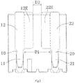
- Fig.2 is a top plan view of the connector shown in Fig.1 .
- the connector mainly comprises a housing 100 and at least one contact (not shown) received in the housing 100.
- a first latch 1 and a second latch 2 for locking a case 200 of a mating connector are provided side by side on a top surface 101 of the housing 100.
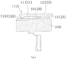
- Fig.3 is a longitudinal cross section view of the connector shown in Fig.1 ;
- Fig.4 is an illustrative perspective view of the connector of Fig.1 mated with a mating connector;
- Fig.5 is a longitudinal cross section view of the connector and the mating connector.
- the first latch 1 comprises a first pressing part 12
- the second latch 2 comprises a second pressing part 22
- the first latch 1 and the second latch 2 may be unlocked by pressing down the first pressing part 12 and the second pressing part 22.
- the first latch 1 and the second latch 2 are arranged on a left side and a right side of the top surface 101 of the housing 100, respectively.
- a distance D1 between the first pressing part 12 and the second pressing part 22 is larger than a width of a finger of an operator. Thereby, the operator cannot press the first pressing part 12 and the second pressing part 22 at the same time with a single finger.
- a first extension portion 12E and a second extension portion 22E adjacent to each other are formed on the first pressing part 12 and the second pressing part 22, respectively.
- the operator may press the first extension portion 12E and the second extension portion 22E at the same time with a single finger.
- the first latch 1 and the second latch 2 may be unlocked at the same time by pressing down the first extension portion 12E and the second extension portion 22E with a single finger.
- the distance D1 between the first pressing part 12 and the second pressing part 22 in the width direction of the housing 100 is larger than the width of the single finger of the operator, but a distance D2 between the first extension portion 12E and the second extension portion 22E in the width direction of the housing 100 is less than the width of the single finger of the operator. Therefore, the operator may press the first extension portion 12E and the second extension portion 22E at the same time with a single finger. Thereby, the first latch 1 and the second latch 2 may be unlocked at the same time by pressing down the first extension portion 12E and the second extension portion 22E with a single finger.
- the distance D1 between the first pressing part 12 and the second pressing part 22 is larger than 30mm; the distance D2 between the first extension portion 12E and the second extension portion 22E is less than 30mm. Since the width of an adult's thumb is usually about 30mm, the operator may press the first extension portion 12E and the second extension portion 22E at the same time with the thumb.
- the distance D1 between the first pressing part 12 and the second pressing part 22 is larger than 40mm; the distance D2 between the first extension portion 12E and the second extension portion 22E is less than 20mm.
- the first latch 1 mainly comprises a first arm 10 and a first elastic support portion 13.
- the first arm 10 horizontally extends in a longitudinal direction of the housing 100.
- the first elastic support portion 13 is connected between the first arm 10 and the housing 100 to support the first arm 10 on the housing 100.
- a front part of the first arm 10 before the first elastic support portion 13 is used as a first latching part 11
- a rear part of the first arm 10 behind the first elastic support portion 13 is used as the first pressing part 11.
- a first hook 11H for locking a protrusion 210P formed on the case 200 of the mating connector is formed on a front end of the first latching part 11.
- the second latch 2 mainly comprises a second arm 20 and a second elastic support portion 23.
- the second arm 20 horizontally extends in the longitudinal direction of the housing 100.
- a second elastic support portion 23 is connected between the second arm 20 and the housing 100 to support the second arm 20 on the housing 100.
- a front part of the second arm 20 before the second elastic support portion 23 is used as a second latching part 21, a rear part of the second arm 20 behind the second elastic support portion 23 is used as the second pressing part 21.
- a second hook 21H for locking a protrusion 220P formed on the case 200 of the mating connector is formed on a front end of the second latching part 21.
- a first slot 210 and a second slot 220 for mating with the first latching part 11 and the second latching part 21, respectively, are formed in the case 200 of the mating connector, the first protrusion 210P and the second protrusion 220P are formed on bottom surfaces of the first slot 210 and the second slot 220, respectively.
- the first latching part 11 and the second latching part 21 are inserted into the first slot 210 and the second slot 220, respectively, and locked to the first protrusion 210P and the second protrusion 220P, respectively.
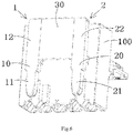
- Fig.6 is another illustrative perspective view of a connector according to an exemplary embodiment of the present invention.
- the connector mainly comprises a housing 100 and at least a contact (not shown) received in the housing 100.
- a first latch 1 and a second latch 2 for locking a case 200 of a mating connector are provided side by side on a top surface 101 of the housing 100, the first latch 1 comprises a first pressing part 12, the second latch 2 comprises a second pressing part 22, the first latch 1 and the second latch 2 may be unlocked by pressing down the first pressing part 12 and the second pressing part 22.
- the first pressing part 12 and the second pressing part 22 are connected by a connection portion 30, so that the first latch 1 and the second latch 2 are capable of being unlocked at the same time by pressing down the connection portion 30 with a single finger of an operator.
- Fig.7 is another illustrative perspective view of a connector according to an exemplary embodiment of the present invention.
- the connector mainly comprises a housing 100 and at least a contact (not shown) received in the housing 100.
- a single latch 1 for locking a case 200 of a mating connector is provided on a top surface 101 of the housing 100, the latch 1 comprises a pressing part 12, the latch 1 may be unlocked by pressing down the pressing part 12.
- an extension portion 12E extending in a width direction of the housing 100 is formed on one side or both sides of the pressing part 12, so that the latch 1 is capable of being unlocked by pressing down the extension portion 12E with a single finger of an operator.
- an extension portion or a connection portion is formed on the pressing parts of the latches, which expands the pressing area of the latch in the width direction of the housing.
Landscapes
- Details Of Connecting Devices For Male And Female Coupling (AREA)
Applications Claiming Priority (2)
| Application Number | Priority Date | Filing Date | Title |
|---|---|---|---|
| CN201810040587.7A CN110048270B (zh) | 2018-01-16 | 2018-01-16 | 连接器外壳和连接器 |
| CN201820067573.XU CN207967430U (zh) | 2018-01-16 | 2018-01-16 | 连接器外壳和连接器 |
Publications (3)
| Publication Number | Publication Date |
|---|---|
| EP3512049A2 true EP3512049A2 (de) | 2019-07-17 |
| EP3512049A3 EP3512049A3 (de) | 2019-10-09 |
| EP3512049B1 EP3512049B1 (de) | 2020-12-30 |
Family
ID=65030987
Family Applications (1)
| Application Number | Title | Priority Date | Filing Date |
|---|---|---|---|
| EP19151840.6A Active EP3512049B1 (de) | 2018-01-16 | 2019-01-15 | Verbindergehäuse und verbinder |
Country Status (2)
| Country | Link |
|---|---|
| US (1) | US10840638B2 (de) |
| EP (1) | EP3512049B1 (de) |
Family Cites Families (9)
| Publication number | Priority date | Publication date | Assignee | Title |
|---|---|---|---|---|
| US3569909A (en) * | 1968-12-26 | 1971-03-09 | Amp Inc | Electrical connector assembly having improved latching means |
| US4602839A (en) * | 1985-01-28 | 1986-07-29 | General Motors Corporation | Electrical connector with multifunction lock means |
| US6364718B1 (en) * | 2001-02-02 | 2002-04-02 | Molex Incorporated | Keying system for electrical connector assemblies |
| TW200910701A (en) * | 2007-08-22 | 2009-03-01 | Delta Electronics Inc | Stacked combination connector and connector assembly |
| CN201142451Y (zh) * | 2007-12-12 | 2008-10-29 | 富士康(昆山)电脑接插件有限公司 | 电连接器组件及其电连接器与壳体 |
| CN102957013A (zh) * | 2011-08-18 | 2013-03-06 | 昆山联滔电子有限公司 | 线缆插头连接器、板端插座连接器及连接器组件 |
| CN103311736A (zh) * | 2012-03-07 | 2013-09-18 | 鸿富锦精密工业(深圳)有限公司 | 连接器拔出辅助装置 |
| JP5765462B1 (ja) * | 2014-04-25 | 2015-08-19 | 第一精工株式会社 | 電気コネクタ |
| JP6944331B2 (ja) * | 2017-05-18 | 2021-10-06 | モレックス エルエルシー | コネクタ及びコネクタ組立体。 |
-
2019
- 2019-01-15 EP EP19151840.6A patent/EP3512049B1/de active Active
- 2019-01-16 US US16/249,297 patent/US10840638B2/en active Active
Non-Patent Citations (1)
| Title |
|---|
| None |
Also Published As
| Publication number | Publication date |
|---|---|
| US10840638B2 (en) | 2020-11-17 |
| US20190221967A1 (en) | 2019-07-18 |
| EP3512049B1 (de) | 2020-12-30 |
| EP3512049A3 (de) | 2019-10-09 |
Similar Documents
| Publication | Publication Date | Title |
|---|---|---|
| EP3289645B1 (de) | Elektrisches verbindersystem mit sekundärverriegelungsvorrichtung | |
| KR101652175B1 (ko) | 커넥터 | |
| US10276980B2 (en) | Connector with a CPA receiving space and connector assembly comprising such a connector | |
| CN104103942B (zh) | 连接器 | |
| US9509093B2 (en) | Connector | |
| JP6787943B2 (ja) | 接続構造及びコネクタ | |
| CN107851934A (zh) | 具有嵌合检测功能的电气连接装置 | |
| JP6569131B2 (ja) | 嵌合検知機能を有する電気接続装置 | |
| CN113571962B (zh) | 连接器以及连接器组件 | |
| JP2017199487A5 (de) | ||
| US9831604B2 (en) | Plug connector system | |
| WO2015200160A1 (en) | Electrical connector | |
| EP3512049A2 (de) | Verbindergehäuse und verbinder | |
| US12224525B2 (en) | Connector and connector assembly | |
| JP2016100113A (ja) | コネクタ | |
| KR101676884B1 (ko) | 커넥터 | |
| US9960540B2 (en) | Connector device | |
| JP6389847B2 (ja) | コネクタ | |
| CN110048270B (zh) | 连接器外壳和连接器 | |
| JP2012074190A (ja) | コネクタ | |
| JP6323229B2 (ja) | コネクタ | |
| US9742114B2 (en) | Connector with a claw of locking member | |
| JP2018060666A (ja) | 接続構造及びコネクタ | |
| CN103904458A (zh) | 电连接器的锁定装置 | |
| JP2022032086A (ja) | コネクタ |
Legal Events
| Date | Code | Title | Description |
|---|---|---|---|
| PUAI | Public reference made under article 153(3) epc to a published international application that has entered the european phase |
Free format text: ORIGINAL CODE: 0009012 |
|
| STAA | Information on the status of an ep patent application or granted ep patent |
Free format text: STATUS: THE APPLICATION HAS BEEN PUBLISHED |
|
| AK | Designated contracting states |
Kind code of ref document: A2 Designated state(s): AL AT BE BG CH CY CZ DE DK EE ES FI FR GB GR HR HU IE IS IT LI LT LU LV MC MK MT NL NO PL PT RO RS SE SI SK SM TR |
|
| AX | Request for extension of the european patent |
Extension state: BA ME |
|
| PUAL | Search report despatched |
Free format text: ORIGINAL CODE: 0009013 |
|
| AK | Designated contracting states |
Kind code of ref document: A3 Designated state(s): AL AT BE BG CH CY CZ DE DK EE ES FI FR GB GR HR HU IE IS IT LI LT LU LV MC MK MT NL NO PL PT RO RS SE SI SK SM TR |
|
| AX | Request for extension of the european patent |
Extension state: BA ME |
|
| RIC1 | Information provided on ipc code assigned before grant |
Ipc: H01R 13/635 20060101ALI20190830BHEP Ipc: H01R 13/627 20060101AFI20190830BHEP |
|
| STAA | Information on the status of an ep patent application or granted ep patent |
Free format text: STATUS: REQUEST FOR EXAMINATION WAS MADE |
|
| 17P | Request for examination filed |
Effective date: 20200325 |
|
| RBV | Designated contracting states (corrected) |
Designated state(s): AL AT BE BG CH CY CZ DE DK EE ES FI FR GB GR HR HU IE IS IT LI LT LU LV MC MK MT NL NO PL PT RO RS SE SI SK SM TR |
|
| GRAP | Despatch of communication of intention to grant a patent |
Free format text: ORIGINAL CODE: EPIDOSNIGR1 |
|
| STAA | Information on the status of an ep patent application or granted ep patent |
Free format text: STATUS: GRANT OF PATENT IS INTENDED |
|
| INTG | Intention to grant announced |
Effective date: 20200720 |
|
| GRAS | Grant fee paid |
Free format text: ORIGINAL CODE: EPIDOSNIGR3 |
|
| GRAA | (expected) grant |
Free format text: ORIGINAL CODE: 0009210 |
|
| STAA | Information on the status of an ep patent application or granted ep patent |
Free format text: STATUS: THE PATENT HAS BEEN GRANTED |
|
| AK | Designated contracting states |
Kind code of ref document: B1 Designated state(s): AL AT BE BG CH CY CZ DE DK EE ES FI FR GB GR HR HU IE IS IT LI LT LU LV MC MK MT NL NO PL PT RO RS SE SI SK SM TR |
|
| REG | Reference to a national code |
Ref country code: GB Ref legal event code: FG4D |
|
| REG | Reference to a national code |
Ref country code: AT Ref legal event code: REF Ref document number: 1350874 Country of ref document: AT Kind code of ref document: T Effective date: 20210115 |
|
| REG | Reference to a national code |
Ref country code: DE Ref legal event code: R096 Ref document number: 602019001894 Country of ref document: DE |
|
| REG | Reference to a national code |
Ref country code: IE Ref legal event code: FG4D |
|
| PG25 | Lapsed in a contracting state [announced via postgrant information from national office to epo] |
Ref country code: FI Free format text: LAPSE BECAUSE OF FAILURE TO SUBMIT A TRANSLATION OF THE DESCRIPTION OR TO PAY THE FEE WITHIN THE PRESCRIBED TIME-LIMIT Effective date: 20201230 Ref country code: RS Free format text: LAPSE BECAUSE OF FAILURE TO SUBMIT A TRANSLATION OF THE DESCRIPTION OR TO PAY THE FEE WITHIN THE PRESCRIBED TIME-LIMIT Effective date: 20201230 Ref country code: NO Free format text: LAPSE BECAUSE OF FAILURE TO SUBMIT A TRANSLATION OF THE DESCRIPTION OR TO PAY THE FEE WITHIN THE PRESCRIBED TIME-LIMIT Effective date: 20210330 Ref country code: GR Free format text: LAPSE BECAUSE OF FAILURE TO SUBMIT A TRANSLATION OF THE DESCRIPTION OR TO PAY THE FEE WITHIN THE PRESCRIBED TIME-LIMIT Effective date: 20210331 |
|
| REG | Reference to a national code |
Ref country code: AT Ref legal event code: MK05 Ref document number: 1350874 Country of ref document: AT Kind code of ref document: T Effective date: 20201230 |
|
| PG25 | Lapsed in a contracting state [announced via postgrant information from national office to epo] |
Ref country code: SE Free format text: LAPSE BECAUSE OF FAILURE TO SUBMIT A TRANSLATION OF THE DESCRIPTION OR TO PAY THE FEE WITHIN THE PRESCRIBED TIME-LIMIT Effective date: 20201230 Ref country code: LV Free format text: LAPSE BECAUSE OF FAILURE TO SUBMIT A TRANSLATION OF THE DESCRIPTION OR TO PAY THE FEE WITHIN THE PRESCRIBED TIME-LIMIT Effective date: 20201230 Ref country code: BG Free format text: LAPSE BECAUSE OF FAILURE TO SUBMIT A TRANSLATION OF THE DESCRIPTION OR TO PAY THE FEE WITHIN THE PRESCRIBED TIME-LIMIT Effective date: 20210330 |
|
| REG | Reference to a national code |
Ref country code: NL Ref legal event code: MP Effective date: 20201230 |
|
| PG25 | Lapsed in a contracting state [announced via postgrant information from national office to epo] |
Ref country code: HR Free format text: LAPSE BECAUSE OF FAILURE TO SUBMIT A TRANSLATION OF THE DESCRIPTION OR TO PAY THE FEE WITHIN THE PRESCRIBED TIME-LIMIT Effective date: 20201230 |
|
| REG | Reference to a national code |
Ref country code: LT Ref legal event code: MG9D |
|
| PG25 | Lapsed in a contracting state [announced via postgrant information from national office to epo] |
Ref country code: SK Free format text: LAPSE BECAUSE OF FAILURE TO SUBMIT A TRANSLATION OF THE DESCRIPTION OR TO PAY THE FEE WITHIN THE PRESCRIBED TIME-LIMIT Effective date: 20201230 Ref country code: EE Free format text: LAPSE BECAUSE OF FAILURE TO SUBMIT A TRANSLATION OF THE DESCRIPTION OR TO PAY THE FEE WITHIN THE PRESCRIBED TIME-LIMIT Effective date: 20201230 Ref country code: CZ Free format text: LAPSE BECAUSE OF FAILURE TO SUBMIT A TRANSLATION OF THE DESCRIPTION OR TO PAY THE FEE WITHIN THE PRESCRIBED TIME-LIMIT Effective date: 20201230 Ref country code: RO Free format text: LAPSE BECAUSE OF FAILURE TO SUBMIT A TRANSLATION OF THE DESCRIPTION OR TO PAY THE FEE WITHIN THE PRESCRIBED TIME-LIMIT Effective date: 20201230 Ref country code: PT Free format text: LAPSE BECAUSE OF FAILURE TO SUBMIT A TRANSLATION OF THE DESCRIPTION OR TO PAY THE FEE WITHIN THE PRESCRIBED TIME-LIMIT Effective date: 20210430 Ref country code: LT Free format text: LAPSE BECAUSE OF FAILURE TO SUBMIT A TRANSLATION OF THE DESCRIPTION OR TO PAY THE FEE WITHIN THE PRESCRIBED TIME-LIMIT Effective date: 20201230 |
|
| PG25 | Lapsed in a contracting state [announced via postgrant information from national office to epo] |
Ref country code: AT Free format text: LAPSE BECAUSE OF FAILURE TO SUBMIT A TRANSLATION OF THE DESCRIPTION OR TO PAY THE FEE WITHIN THE PRESCRIBED TIME-LIMIT Effective date: 20201230 Ref country code: PL Free format text: LAPSE BECAUSE OF FAILURE TO SUBMIT A TRANSLATION OF THE DESCRIPTION OR TO PAY THE FEE WITHIN THE PRESCRIBED TIME-LIMIT Effective date: 20201230 |
|
| PG25 | Lapsed in a contracting state [announced via postgrant information from national office to epo] |
Ref country code: LU Free format text: LAPSE BECAUSE OF NON-PAYMENT OF DUE FEES Effective date: 20210115 Ref country code: IS Free format text: LAPSE BECAUSE OF FAILURE TO SUBMIT A TRANSLATION OF THE DESCRIPTION OR TO PAY THE FEE WITHIN THE PRESCRIBED TIME-LIMIT Effective date: 20210430 |
|
| REG | Reference to a national code |
Ref country code: DE Ref legal event code: R097 Ref document number: 602019001894 Country of ref document: DE |
|
| REG | Reference to a national code |
Ref country code: BE Ref legal event code: MM Effective date: 20210131 |
|
| PG25 | Lapsed in a contracting state [announced via postgrant information from national office to epo] |
Ref country code: IT Free format text: LAPSE BECAUSE OF FAILURE TO SUBMIT A TRANSLATION OF THE DESCRIPTION OR TO PAY THE FEE WITHIN THE PRESCRIBED TIME-LIMIT Effective date: 20201230 Ref country code: MC Free format text: LAPSE BECAUSE OF FAILURE TO SUBMIT A TRANSLATION OF THE DESCRIPTION OR TO PAY THE FEE WITHIN THE PRESCRIBED TIME-LIMIT Effective date: 20201230 Ref country code: AL Free format text: LAPSE BECAUSE OF FAILURE TO SUBMIT A TRANSLATION OF THE DESCRIPTION OR TO PAY THE FEE WITHIN THE PRESCRIBED TIME-LIMIT Effective date: 20201230 |
|
| PLBE | No opposition filed within time limit |
Free format text: ORIGINAL CODE: 0009261 |
|
| STAA | Information on the status of an ep patent application or granted ep patent |
Free format text: STATUS: NO OPPOSITION FILED WITHIN TIME LIMIT |
|
| PG25 | Lapsed in a contracting state [announced via postgrant information from national office to epo] |
Ref country code: DK Free format text: LAPSE BECAUSE OF FAILURE TO SUBMIT A TRANSLATION OF THE DESCRIPTION OR TO PAY THE FEE WITHIN THE PRESCRIBED TIME-LIMIT Effective date: 20201230 |
|
| 26N | No opposition filed |
Effective date: 20211001 |
|
| PG25 | Lapsed in a contracting state [announced via postgrant information from national office to epo] |
Ref country code: ES Free format text: LAPSE BECAUSE OF FAILURE TO SUBMIT A TRANSLATION OF THE DESCRIPTION OR TO PAY THE FEE WITHIN THE PRESCRIBED TIME-LIMIT Effective date: 20201230 Ref country code: FR Free format text: LAPSE BECAUSE OF NON-PAYMENT OF DUE FEES Effective date: 20210228 Ref country code: IE Free format text: LAPSE BECAUSE OF NON-PAYMENT OF DUE FEES Effective date: 20210115 |
|
| PG25 | Lapsed in a contracting state [announced via postgrant information from national office to epo] |
Ref country code: SI Free format text: LAPSE BECAUSE OF FAILURE TO SUBMIT A TRANSLATION OF THE DESCRIPTION OR TO PAY THE FEE WITHIN THE PRESCRIBED TIME-LIMIT Effective date: 20201230 |
|
| PG25 | Lapsed in a contracting state [announced via postgrant information from national office to epo] |
Ref country code: IS Free format text: LAPSE BECAUSE OF FAILURE TO SUBMIT A TRANSLATION OF THE DESCRIPTION OR TO PAY THE FEE WITHIN THE PRESCRIBED TIME-LIMIT Effective date: 20210430 |
|
| PG25 | Lapsed in a contracting state [announced via postgrant information from national office to epo] |
Ref country code: BE Free format text: LAPSE BECAUSE OF NON-PAYMENT OF DUE FEES Effective date: 20210131 |
|
| REG | Reference to a national code |
Ref country code: CH Ref legal event code: PL |
|
| PG25 | Lapsed in a contracting state [announced via postgrant information from national office to epo] |
Ref country code: LI Free format text: LAPSE BECAUSE OF NON-PAYMENT OF DUE FEES Effective date: 20220131 Ref country code: CH Free format text: LAPSE BECAUSE OF NON-PAYMENT OF DUE FEES Effective date: 20220131 |
|
| PG25 | Lapsed in a contracting state [announced via postgrant information from national office to epo] |
Ref country code: NL Free format text: LAPSE BECAUSE OF NON-PAYMENT OF DUE FEES Effective date: 20201230 Ref country code: CY Free format text: LAPSE BECAUSE OF FAILURE TO SUBMIT A TRANSLATION OF THE DESCRIPTION OR TO PAY THE FEE WITHIN THE PRESCRIBED TIME-LIMIT Effective date: 20201230 |
|
| PG25 | Lapsed in a contracting state [announced via postgrant information from national office to epo] |
Ref country code: SM Free format text: LAPSE BECAUSE OF FAILURE TO SUBMIT A TRANSLATION OF THE DESCRIPTION OR TO PAY THE FEE WITHIN THE PRESCRIBED TIME-LIMIT Effective date: 20201230 Ref country code: HU Free format text: LAPSE BECAUSE OF FAILURE TO SUBMIT A TRANSLATION OF THE DESCRIPTION OR TO PAY THE FEE WITHIN THE PRESCRIBED TIME-LIMIT; INVALID AB INITIO Effective date: 20190115 |
|
| GBPC | Gb: european patent ceased through non-payment of renewal fee |
Effective date: 20230115 |
|
| PG25 | Lapsed in a contracting state [announced via postgrant information from national office to epo] |
Ref country code: GB Free format text: LAPSE BECAUSE OF NON-PAYMENT OF DUE FEES Effective date: 20230115 |
|
| PG25 | Lapsed in a contracting state [announced via postgrant information from national office to epo] |
Ref country code: MK Free format text: LAPSE BECAUSE OF FAILURE TO SUBMIT A TRANSLATION OF THE DESCRIPTION OR TO PAY THE FEE WITHIN THE PRESCRIBED TIME-LIMIT Effective date: 20201230 |
|
| PG25 | Lapsed in a contracting state [announced via postgrant information from national office to epo] |
Ref country code: MT Free format text: LAPSE BECAUSE OF FAILURE TO SUBMIT A TRANSLATION OF THE DESCRIPTION OR TO PAY THE FEE WITHIN THE PRESCRIBED TIME-LIMIT Effective date: 20201230 |
|
| PG25 | Lapsed in a contracting state [announced via postgrant information from national office to epo] |
Ref country code: TR Free format text: LAPSE BECAUSE OF FAILURE TO SUBMIT A TRANSLATION OF THE DESCRIPTION OR TO PAY THE FEE WITHIN THE PRESCRIBED TIME-LIMIT Effective date: 20201230 |
|
| PGFP | Annual fee paid to national office [announced via postgrant information from national office to epo] |
Ref country code: DE Payment date: 20251203 Year of fee payment: 8 |