EP3512018B1 - Systeme und verfahren zur stromerzeugung unter verwendung von brennstoffzellen - Google Patents
Systeme und verfahren zur stromerzeugung unter verwendung von brennstoffzellen Download PDFInfo
- Publication number
- EP3512018B1 EP3512018B1 EP19150670.8A EP19150670A EP3512018B1 EP 3512018 B1 EP3512018 B1 EP 3512018B1 EP 19150670 A EP19150670 A EP 19150670A EP 3512018 B1 EP3512018 B1 EP 3512018B1
- Authority
- EP
- European Patent Office
- Prior art keywords
- fuel cell
- generation system
- power generation
- power
- bus
- Prior art date
- Legal status (The legal status is an assumption and is not a legal conclusion. Google has not performed a legal analysis and makes no representation as to the accuracy of the status listed.)
- Active
Links
Images


Classifications
-
- H—ELECTRICITY
- H01—ELECTRIC ELEMENTS
- H01M—PROCESSES OR MEANS, e.g. BATTERIES, FOR THE DIRECT CONVERSION OF CHEMICAL ENERGY INTO ELECTRICAL ENERGY
- H01M8/00—Fuel cells; Manufacture thereof
- H01M8/04—Auxiliary arrangements, e.g. for control of pressure or for circulation of fluids
-
- H—ELECTRICITY
- H01—ELECTRIC ELEMENTS
- H01M—PROCESSES OR MEANS, e.g. BATTERIES, FOR THE DIRECT CONVERSION OF CHEMICAL ENERGY INTO ELECTRICAL ENERGY
- H01M8/00—Fuel cells; Manufacture thereof
- H01M8/04—Auxiliary arrangements, e.g. for control of pressure or for circulation of fluids
- H01M8/04298—Processes for controlling fuel cells or fuel cell systems
- H01M8/04694—Processes for controlling fuel cells or fuel cell systems characterised by variables to be controlled
- H01M8/04858—Electric variables
- H01M8/04865—Voltage
- H01M8/0488—Voltage of fuel cell stacks
-
- H—ELECTRICITY
- H01—ELECTRIC ELEMENTS
- H01M—PROCESSES OR MEANS, e.g. BATTERIES, FOR THE DIRECT CONVERSION OF CHEMICAL ENERGY INTO ELECTRICAL ENERGY
- H01M8/00—Fuel cells; Manufacture thereof
- H01M8/04—Auxiliary arrangements, e.g. for control of pressure or for circulation of fluids
- H01M8/04082—Arrangements for control of reactant parameters, e.g. pressure or concentration
- H01M8/04089—Arrangements for control of reactant parameters, e.g. pressure or concentration of gaseous reactants
-
- H—ELECTRICITY
- H01—ELECTRIC ELEMENTS
- H01M—PROCESSES OR MEANS, e.g. BATTERIES, FOR THE DIRECT CONVERSION OF CHEMICAL ENERGY INTO ELECTRICAL ENERGY
- H01M8/00—Fuel cells; Manufacture thereof
- H01M8/04—Auxiliary arrangements, e.g. for control of pressure or for circulation of fluids
- H01M8/04298—Processes for controlling fuel cells or fuel cell systems
- H01M8/04313—Processes for controlling fuel cells or fuel cell systems characterised by the detection or assessment of variables; characterised by the detection or assessment of failure or abnormal function
- H01M8/04537—Electric variables
- H01M8/04544—Voltage
- H01M8/04559—Voltage of fuel cell stacks
-
- H—ELECTRICITY
- H02—GENERATION; CONVERSION OR DISTRIBUTION OF ELECTRIC POWER
- H02J—CIRCUIT ARRANGEMENTS OR SYSTEMS FOR SUPPLYING OR DISTRIBUTING ELECTRIC POWER; SYSTEMS FOR STORING ELECTRIC ENERGY
- H02J1/00—Circuit arrangements for DC mains or DC distribution networks
-
- H—ELECTRICITY
- H02—GENERATION; CONVERSION OR DISTRIBUTION OF ELECTRIC POWER
- H02J—CIRCUIT ARRANGEMENTS OR SYSTEMS FOR SUPPLYING OR DISTRIBUTING ELECTRIC POWER; SYSTEMS FOR STORING ELECTRIC ENERGY
- H02J3/00—Circuit arrangements for AC mains or AC distribution networks
-
- H—ELECTRICITY
- H02—GENERATION; CONVERSION OR DISTRIBUTION OF ELECTRIC POWER
- H02J—CIRCUIT ARRANGEMENTS OR SYSTEMS FOR SUPPLYING OR DISTRIBUTING ELECTRIC POWER; SYSTEMS FOR STORING ELECTRIC ENERGY
- H02J3/00—Circuit arrangements for AC mains or AC distribution networks
- H02J3/38—Arrangements for parallely feeding a single network by two or more generators, converters or transformers
- H02J3/381—Dispersed generators
-
- H—ELECTRICITY
- H02—GENERATION; CONVERSION OR DISTRIBUTION OF ELECTRIC POWER
- H02M—APPARATUS FOR CONVERSION BETWEEN AC AND AC, BETWEEN AC AND DC, OR BETWEEN DC AND DC, AND FOR USE WITH MAINS OR SIMILAR POWER SUPPLY SYSTEMS; CONVERSION OF DC OR AC INPUT POWER INTO SURGE OUTPUT POWER; CONTROL OR REGULATION THEREOF
- H02M7/00—Conversion of AC power input into DC power output; Conversion of DC power input into AC power output
- H02M7/66—Conversion of AC power input into DC power output; Conversion of DC power input into AC power output with possibility of reversal
- H02M7/68—Conversion of AC power input into DC power output; Conversion of DC power input into AC power output with possibility of reversal by static converters
- H02M7/72—Conversion of AC power input into DC power output; Conversion of DC power input into AC power output with possibility of reversal by static converters using discharge tubes with control electrode or semiconductor devices with control electrode
- H02M7/79—Conversion of AC power input into DC power output; Conversion of DC power input into AC power output with possibility of reversal by static converters using discharge tubes with control electrode or semiconductor devices with control electrode using devices of a triode or transistor type requiring continuous application of a control signal
- H02M7/797—Conversion of AC power input into DC power output; Conversion of DC power input into AC power output with possibility of reversal by static converters using discharge tubes with control electrode or semiconductor devices with control electrode using devices of a triode or transistor type requiring continuous application of a control signal using semiconductor devices only
-
- H—ELECTRICITY
- H01—ELECTRIC ELEMENTS
- H01M—PROCESSES OR MEANS, e.g. BATTERIES, FOR THE DIRECT CONVERSION OF CHEMICAL ENERGY INTO ELECTRICAL ENERGY
- H01M8/00—Fuel cells; Manufacture thereof
- H01M8/04—Auxiliary arrangements, e.g. for control of pressure or for circulation of fluids
- H01M8/04223—Auxiliary arrangements, e.g. for control of pressure or for circulation of fluids during start-up or shut-down; Depolarisation or activation, e.g. purging; Means for short-circuiting defective fuel cells
- H01M8/04268—Heating of fuel cells during the start-up of the fuel cells
-
- H02J2101/30—
-
- Y—GENERAL TAGGING OF NEW TECHNOLOGICAL DEVELOPMENTS; GENERAL TAGGING OF CROSS-SECTIONAL TECHNOLOGIES SPANNING OVER SEVERAL SECTIONS OF THE IPC; TECHNICAL SUBJECTS COVERED BY FORMER USPC CROSS-REFERENCE ART COLLECTIONS [XRACs] AND DIGESTS
- Y02—TECHNOLOGIES OR APPLICATIONS FOR MITIGATION OR ADAPTATION AGAINST CLIMATE CHANGE
- Y02E—REDUCTION OF GREENHOUSE GAS [GHG] EMISSIONS, RELATED TO ENERGY GENERATION, TRANSMISSION OR DISTRIBUTION
- Y02E60/00—Enabling technologies; Technologies with a potential or indirect contribution to GHG emissions mitigation
- Y02E60/30—Hydrogen technology
- Y02E60/50—Fuel cells
Definitions
- Embodiments of the present specification generally relate to a fuel cell based power generation system and method of operating the fuel cell based power generation system, and more particularly to systems and methods for powering auxiliary subunits of the fuel cell based power generation system.
- a fuel cell based power generation system includes a stack of fuel cells, auxiliary subunits, and associated circuitry.
- the auxiliary subunits typically include a fuel blower, an air blower, an air ventilator, associated motors, and the like.
- the auxiliary subunits are powered using an external power source, which in turn aids in heating the stack of fuel cells.
- the stack of fuel cells is heated for a time-period in a range from about 8 hours to about 12 hours until the stack of fuel cells attains a determined temperature at which the stack of fuel cells starts generating electric power. The longer the time required for heating up the stack of fuel cells, the more power is consumed from the external power source for powering of the auxiliary subunits.
- the electric power required for powering the auxiliary subunits is provided from the heated stack of fuel cells.
- auxiliary subunits Different systems and techniques for providing power to the auxiliary subunits have been proposed.
- Conventional systems used for providing power to the auxiliary subunits call for use of power converters such as direct current (DC)-DC converters, buck boost converters, and the like.
- DC direct current
- buck boost converters buck boost converters
- the auxiliary subunits are coupled to a DC bus and the stack of fuel cells is coupled to the DC bus via power converters.
- certain other conventional systems for providing power to the auxiliary subunits entail coupling the auxiliary subunits to both the DC bus and an alternating current (AC) bus.
- AC alternating current
- DC-AC-DC-AC three stage power conversion units
- Use of the DC-DC converters, the buck boost converters, and/or the three stage power conversion units for powering the auxiliary subunits adds to cost, footprint, and complexity of the power generation systems and reduces efficiency.
- US 2014/302415 A1 discloses an apparatus for heating a fuel cell stack in a cold start mode, comprising a fuel cell stack, a power converter, and a controller, wherein the power converter may include a power switch and resistive heating element that is thermally coupled to the fuel cell stack; the controller is configured to activate the power converter, if a temperature is below a predetermined temperature value, to draw current from the fuel cell stack to cause the fuel cell stack to generate heat; and heat from the power converter is also applied to the fuel cell stack.
- US 2011/217615 A1 discloses a fuel cell stabilisation system for stabilising the supply of electrical power from a fuel cell stack to a DC bus, including: a DC power supply; and a control configured to enable the DC power supply to supply electrical power to the DC bus.
- US 2013/253716 A1 discloses a system including a power module comprising at least one fuel cell generator for powering a load, and a bypass mechanism having a first, normally-open fast-acting switch that closes in 1-250 msec, and a second, normally-open switch in parallel with the first switch, the bypass mechanism being electrically connected between the load and a second power source, such as a grid source, where the first switch is configured to close in response to a fault event such that when the first switch is closed power to the load is provided from the second power source through the first switch, and the second switch closes after a predetermined time such that power to the load from the second source is provided through the second switch.
- a power module comprising at least one fuel cell generator for powering a load
- a bypass mechanism having a first, normally-open fast-acting switch that closes in 1-250 msec, and a second, normally-open switch in parallel with the first switch, the bypass mechanism being electrically connected between the load and a second power source, such as
- a fuel cell based power generation system in accordance with claim 1.
- the fuel cell based power generation system includes a fuel cell assembly configured to generate a DC power. Further, the fuel cell based power generation system includes at least one assembly switching element configured to operatively couple the fuel cell assembly to a first direct current (DC) bus. Furthermore, the fuel cell based power generation system includes at least one converter coupled between the first DC bus and an electrical grid.
- DC direct current
- the fuel cell based power generation system includes a plurality of auxiliary loads operatively coupled to the first DC bus at a location between the at least one assembly switching element and the at least one converter, where at least one of the plurality of auxiliary loads is configured to receive power from the fuel cell assembly via the at least one assembly switching element and a controller operatively coupled to the at least one converter, where the controller is configured to allow a voltage of the first DC bus to fluctuate within a range of voltage values.
- a method for operating a fuel cell based power generation system where the fuel cell based power generation system includes a fuel cell assembly, at least one assembly switching element and a plurality of auxiliary loads operatively coupled to a first direct current (DC) bus is presented.
- the method includes heating the fuel cell assembly in a plurality of stages, where the plurality of stages includes at least a first stage and a second stage.
- the heating the fuel cell assembly includes during the first stage of the plurality of stages, powering at least one first auxiliary load corresponding to a portion or portions of the fuel cell assembly to heat the portion or portions of the fuel cell assembly.
- heating the fuel cell assembly includes generating, using the portion or portions of the fuel cell assembly, a first DC power.
- heating the fuel cell assembly includes during the second stage of the plurality of stages, powering at least one second auxiliary load corresponding to another portion or portions of the fuel cell assembly to heat the another portion or portions of the fuel cell assembly based at least in part on the first DC power to generate a second DC power.
- connection and “coupled” are not restricted to physical or mechanical connections or couplings, and can include electrical connections or couplings, whether direct or indirect.
- operatively coupled refers to direct and indirect coupling.
- circuit and circuitry and “controller” may include either a single component or a plurality of components, which are either active and/or passive and are connected or otherwise coupled together to provide the described function.
- the exemplary fuel cell based power generation system may be employed in distributed power generation applications, micro-power generation, small-scale energy generation, and/or larger-scale applications, such as power plants or power stations. Also, the exemplary fuel cell based power generation system may be used in the automotive industry.
- the fuel cell based power generation system employs at least one switching element for coupling a fuel cell assembly to a direct current (DC) bus.
- the switching element is devoid of controllable semiconductor switches, thereby reducing operational complexity and cost of the fuel cell based power generation system.
- the DC bus is coupled to an electrical grid via a bidirectional converter.
- the fuel cell assembly 202 includes fuel cell units 212, 214, 216, and 218.
- Each of the fuel cell units 212, 214, 216, and 218 may include a plurality of fuel cell subunits (shown in FIG. 3 ).
- the fuel cell assembly 202 may operate in conjunction with the corresponding auxiliary loads 234.
- the fuel cell assembly 202 operates in conjunction with components (not shown in FIG. 2 ) such as a natural gas pipeline, a burner, catalytic partial oxidation (CPOx) reformer, a heater, or the like.
- the converter 232 is configured to import power from the electrical grid 230. Consequently, the converter 232 is configured to "regulate" transfer of power between the electrical grid 230 and the first DC bus 204 thereby aiding in maintaining the voltage of the first DC bus 204 within the above-discussed range of voltage values.
- the first and second sets of fuel cell subunits 318, 320 are in fluid communication, thereby aiding in supply of exhaust gas from the second set of fuel cell subunits 320 to the first set of fuel cell subunits 318.
- the exhaust gas of the first set of fuel cell subunits 318 includes unreacted fuel, which may include methane, carbon monoxide, carbon dioxide, hydrogen, and steam.
- auxiliary loads corresponding to the first set of fuel cell subunits 318.
- the external power source may be an electrical grid, such as the electrical grid 230 of FIG. 2 .
- the first set of fuel cell subunits 318 is heated based on the power provided from the electrical grid to the corresponding auxiliary loads. Once the first set of fuel cell subunits 318 attains a determined temperature value, the first set of fuel cell subunits 318 generates a corresponding DC power.
- the DC power generated by the first set of fuel cell subunits 318 is referred to as a fourth DC power
- the fourth DC power is conveyed from the first set of fuel cell subunits to the auxiliary loads of the fuel cell unit 300 via the subunit DC bus 313. It may be noted that the fourth DC power is provided to the auxiliary loads in addition to the power provided from the electrical grid 230. The supply of power from the electrical grid 230 to the auxiliary loads is reduced in light of supply of the fourth DC power from the fuel cell unit 300. Thus, less power is imported from the electrical grid 230. At a certain point in time, if the fourth DC power is sufficient for powering all the auxiliary loads of the fuel cell unit 300, no power may be drawn from the external power source.
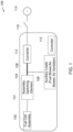
- FIG. 4 is a diagrammatical representation 400 of another embodiment of the fuel cell based power generation system 101 of FIG. 1 , according to aspects of the present specification.
- FIG. 4 represents a fuel cell based power generation system 401 including a plurality of fuel cell units 402, a plurality of assembly switching elements 404, a first DC bus 406, and a converter 410.
- the fuel cell based power generation system 401 is coupled to an external power source, such an electrical grid 408.
- the external power source may be a battery, an uninterruptible power supply (UPS), a solar based power source, a wind turbine based power source, a thermoelectric device, and another fuel cell based power generation system.
- the converter 410 is a bidirectional inverter.
- the first DC bus 406 is a main DC bus and is operatively coupled to the electrical grid 408 via the converter 410.
- the fuel cell based power generation system 401 includes a second DC bus 414 and an auxiliary load 416.
- the second DC bus 414 is an auxiliary DC bus and is operatively coupled to the first DC bus 406 via an auxiliary switching element 417.
- the second DC bus is coupled between the auxiliary loads 416 and the first DC bus 406 via the auxiliary switching element 417.
- the auxiliary switching element 417 includes a switch 418 and a blocking diode 420.
- the switch 418 is a relay.
- the blocking diode 420 ensures that power flows in a single direction from the first DC bus 406 to the second DC bus 414. It may be noted that in the illustrated embodiment of FIG.
- the auxiliary load 416 is coupled to the second DC bus 414. In this embodiment, the auxiliary load 416 is indirectly coupled to the first DC bus 406.
- the additional DC power source 412 may be used to supply power to at least some of the auxiliary loads 416 of at least one of the fuel cell units of the plurality of fuel cell units. Use of the additional DC power source 412 in the fuel cell based power generation system 401 enables black start of the auxiliary loads 416.
- the phrase 'black start of the auxiliary loads,' as used herein, refers to initial powering of the auxiliary loads even if the electrical grid 408 is de-coupled from the first DC bus 406. Accordingly, implementing the system 401 as described with reference to FIG. 4 aids in ensuring an uninterrupted supply of power to the auxiliary load 416 even in the absence of supply of power from the electrical grid 408.
- FIG. 5 is a flow chart 500 representing a method for operating the fuel cell based power generation system 101 of FIG. 1 , according to aspects of the present specification. The method of FIG. 5 is described with respect to the components of FIGs. 1 and 2 .
- the method 500 for operating the fuel cell based power generation system 101 includes heating the fuel cell assembly 202 in a plurality of stages, as indicated by step 502.
- the plurality of stages includes at least a first stage and a second stage.
- step 502 of heating the fuel cell assembly 202 in the plurality of stages includes sub-steps 504, 506, and 508.
- at sub-step 504 during the first stage of the plurality of stages, at least one first auxiliary load corresponding to at least one fuel cell unit of the plurality of fuel cell units is powered to heat the at least one fuel cell unit.
- the at least one fuel cell unit attains a determined temperature value consequent to the heating of the at least one fuel cell unit.
- the auxiliary load 238 is provided power from the electrical grid 230 via the converter 232. Consequently, the first fuel cell unit 212 is heated.
- the first auxiliary load 238 corresponds to the first fuel cell unit 212.
- the first auxiliary load 238 aids in heating the first fuel cell unit 212.
- a first DC power is generated using the heated at least one fuel cell unit.
- the first fuel cell unit 212 heated at sub-step 504 generates a first DC power once the first fuel cell unit 212 attains the determined temperature value.
- the determined temperature value is 750° C.
- This first DC power is provided to the first DC bus 204. If the value of the first DC power generated by the first fuel cell unit 212 is sufficient to meet the power requirement of the first auxiliary load 238, the first auxiliary load 238 is provided power from the first fuel cell unit 212 instead of from the electrical grid 230.
- the first DC power generated by the first fuel cell unit 212 along with the power from the electrical grid 230 is provided to the auxiliary loads 240, 242, 244 of the other fuel cell units 214, 216, 218. Consequently, the other fuel cell units 214, 216, 218 are heated.
- the converter 232 is configured to stop import of power from the electrical grid 230 for powering the auxiliary loads 240, 242, 244.
- the other fuel cell units 214, 216, 218 are heated based only on the generated first DC power.
- the other fuel cell units 214, 216, 218 generate the second DC power based on the heating of the other fuel cell units 214, 216, 218.
- the second DC power is also provided to the first DC bus 204.
- a portion of the first DC power and the second DC power is used to power the auxiliary loads 240, 242, 244. Further, the remaining portion of the first DC power and the second DC power is provided to the electrical grid 230 via the converter 232.
- the controller 112 of FIG. 1 is employed to regulate the converter 232 such that if the first and second DC powers supplied to the first DC bus 204 from the fuel cell assembly 202 exceeds a threshold value, excess power is provided to the electrical grid 230 via the converter 232. Supplying the excess power to the electrical grid 230 by the converter 232 aids in allowing the voltage of the first DC bus 204 to fluctuate within a range of voltage values.
- the voltage of the first DC bus 204 may vary between a lower limit of voltage and an upper limit of voltage.
- the lower limit and the upper limit of voltage may be determined using the controller 112.
- a processor-based system such as a general-purpose or special-purpose computer.
- different implementations of the present technique may perform some or all of the steps described herein in different orders or substantially concurrently, that is, in parallel.
- the functions may be implemented in a variety of programming languages, including but not limited to C++ or Java.
- Such code may be stored or adapted for storage on one or more tangible, machine readable media, such as on data repository chips, local or remote hard disks, optical disks (that is, CDs or DVDs), memory or other media, which may be accessed by a processor-based system to execute the stored code.
- tangible media may comprise paper or another suitable medium upon which the instructions are printed.
- the instructions may be electronically captured via optical scanning of the paper or other medium, then compiled, interpreted or otherwise processed in a suitable manner if necessary, and then stored in the data repository or memory.
- a fuel cell based power generation system and a method of operating the fuel cell based power generation system are presented.
- the systems and methods presented herein aid in heating the fuel cells of the fuel assembly in two stages.
- Use of the exemplary fuel cell based power generation system aids in heating a larger set of fuel cells using power provided by a smaller set of fuel cells and the external power source, instead of importing power entirely from the external power source.
- use of the exemplary fuel cell based power generation system aids in lowering the power consumed from the external power source.
- the fuel cell based power generation system uses switching elements which in turn include switches.
- the exemplary fuel cell based power generation system may be employed in distributed power generation applications, micro-power generation, small-scale energy generation or larger applications, such as power plants or power stations. Also, the exemplary fuel cell based power generation system may find application in the automotive industry.
Landscapes
- Engineering & Computer Science (AREA)
- Power Engineering (AREA)
- Life Sciences & Earth Sciences (AREA)
- Manufacturing & Machinery (AREA)
- Sustainable Development (AREA)
- Sustainable Energy (AREA)
- Chemical & Material Sciences (AREA)
- Chemical Kinetics & Catalysis (AREA)
- Electrochemistry (AREA)
- General Chemical & Material Sciences (AREA)
- Fuel Cell (AREA)
Claims (15)
- Brennstoffzellen-basiertes Energieerzeugungssystem (101), umfassend:eine Brennstoffzellenbaugruppe (102), die dazu konfiguriert ist, eine DC-Energie zu erzeugen, wobei die Brennstoffzellenbaugruppe (102) eine Vielzahl von Brennstoffzelleneinheiten (212, 214, 216, 218) umfasst, die betriebsfähig miteinander gekoppelt sind;mindestens ein Baugruppenumschaltelement (104), das dazu konfiguriert ist, die Brennstoffzellenbaugruppe (102) mit einem ersten Gleichstrom- (DC-) Bus (106) betriebsfähig zu koppeln;mindestens einen Wandler (110), der zwischen dem ersten DC-Bus und einem Elektrizitätsnetz (114) gekoppelt ist;eine Vielzahl von Hilfslasten (108), die betriebsfähig mit dem ersten DC-Bus an einem Ort zwischen dem mindestens einen Baugruppenumschaltelement und dem mindestens einen Wandler gekoppelt sind, wobei jede Brennstoffzelleneinheit (212, 214, 216, 218) eine entsprechende Hilfslast (108) aufweist, wobei die Hilfslasten dazu konfiguriert sind, die Brennstoffzellenbaugruppe in einer Vielzahl von Phasen aufzuheizen, und wobei mindestens eine der Vielzahl von Hilfslasten dazu konfiguriert ist, Energie von der Brennstoffzellenbaugruppe über das mindestens eine Baugruppenumschaltelement zu empfangen; undeine Steuerung (112), die betriebsfähig mit dem mindestens einen Wandler (110) gekoppelt ist, wobei die Steuerung dazu konfiguriert ist, einer Spannung des ersten DC-Busses zu ermöglichen, innerhalb eines Bereichs von Spannungswerten zu schwanken.
- Brennstoffzellen-basiertes Energieerzeugungssystem (101) nach Anspruch 1, wobei der mindestens eine Wandler (110) dazu konfiguriert ist, elektrische Energie zwischen dem Elektrizitätsnetz und mindestens einer der Vielzahl von Hilfslasten und der Brennstoffzellenbaugruppe zu übertragen.
- Brennstoffzellen-basiertes Energieerzeugungssystem (101) nach einem der vorhergehenden Ansprüche, ferner umfassend eine DC-Energiequelle (412), die dazu konfiguriert ist, Energie an mindestens einige der Vielzahl von Hilfslasten (108) während eines Hochfahrens der Brennstoffzellenbaugruppe bereitzustellen.
- Brennstoffzellen-basiertes Energieerzeugungssystem (101) nach einem der vorhergehenden Ansprüche, wobei das mindestens eine Baugruppenumschaltelement (104) eine Sicherung, ein Relais, einen manuell betriebenen Schalter, einen mechanisch betriebenen Schalter, einen elektromechanisch betriebenen Schalter, einen magnetisch betriebenen Schalter oder Kombinationen daraus umfasst.
- Brennstoffzellen-basiertes Energieerzeugungssystem (101) nach einem der vorhergehenden Ansprüche, wobei jede der Vielzahl von Brennstoffzelleneinheiten eine Vielzahl von Brennstoffzellenuntereinheiten (302) umfasst.
- Brennstoffzellen-basiertes Energieerzeugungssystem (101) nach Anspruch 5, ferner umfassend eine Vielzahl von Untereinheitumschalteinheiten, und wobei die Vielzahl von Untereinheitumschaltelementen (304) dazu konfiguriert ist, die Vielzahl von Brennstoffzellenuntereinheiten (302) betriebsfähig miteinander zu koppeln.
- Brennstoffzellen-basiertes Energieerzeugungssystem (101) nach Anspruch 5 oder 6, wobei die eine oder die mehreren Brennstoffzellenuntereinheiten (302) der Vielzahl von Brennstoffzellenuntereinheiten dazu konfiguriert sind, mindestens eines aus einem frischen Brennstoff und einem Abgas von anderen Brennstoffzellenuntereinheiten der Vielzahl von Brennstoffuntereinheiten zu empfangen, und die anderen Brennstoffzellenuntereinheiten der Vielzahl von Brennstoffzellenuntereinheiten dazu konfiguriert sind, den frischen Brennstoff zu empfangen.
- Brennstoffzellen-basiertes Energieerzeugungssystem (101) nach einem der vorhergehenden Ansprüche, ferner umfassend einen zweiten DC-Bus (414), der zwischen der Vielzahl von Hilfslasten (108) und dem ersten DC-Bus über ein Hilfsumschaltelement gekoppelt ist.
- Brennstoffzellen-basiertes Energieerzeugungssystem (101) nach Anspruch 8, wobei eine Spannung des zweiten DC-Busses (414) niedriger ist als eine Spannung des ersten DC-Busses (106).
- Brennstoffzellen-basiertes Energieerzeugungssystem (101) nach einem der vorhergehenden Ansprüche, wobei der Bereich von Spannungswerten in einem Bereich von etwa 345 Volt bis etwa 420 Volt liegt.
- Brennstoffzellen-basiertes Energieerzeugungssystem (101) nach einem der vorhergehenden Ansprüche, wobei die Vielzahl von Hilfslasten (108) mindestens eines aus einem Brennstoffgebläse, einem Luftgebläse und einem Luftventilator umfasst.
- Verfahren (500) zum Betreiben eines Brennstoffzellen-basierten Energieerzeugungssystems (101), wobei das Brennstoffzellen-basierte Energieerzeugungssystem eine Brennstoffzellenbaugruppe, mindestens ein Baugruppenumschaltelement und eine Vielzahl von Hilfslasten umfasst, die betriebsfähig mit einem ersten Gleichstrom- (DC-) Bus gekoppelt sind, das Verfahren umfassend:
Aufheizen (502) der Brennstoffzellenbaugruppe in einer Vielzahl von Phasen, wobei die Vielzahl von Phasen mindestens eine erste Phase und eine zweite Phase umfasst, und wobei das Aufheizen der Brennstoffzellenbaugruppe Folgendes umfasst:während der ersten Phase der Vielzahl von Phasen (504), Versorgen mindestens einer ersten Hilfslast, die einem Teil oder Teilen der Brennstoffzellenbaugruppe entspricht, mit Energie, um den Teil oder die Teile der Brennstoffzellenbaugruppe aufzuheizen;Erzeugen (506), unter Verwendung des Teils oder der Teile der Brennstoffzellenbaugruppe, einer ersten DC-Energie; undwährend der zweiten Phase der Vielzahl von Phasen (508), Versorgen mindestens einer zweiten Hilfslast, die einem anderen Teil oder anderen Teilen der Brennstoffzellenbaugruppe entspricht, mit Energie, um den anderen Teil oder die anderen Teile der Brennstoffzellenbaugruppe auf Basis mindestens teilweise der ersten DC-Energie aufzuheizen, um eine zweite DC-Energie zu erzeugen. - Verfahren (500) nach Anspruch 12, wobei das Versorgen der mindestens einen ersten Hilfslast mit Energie das Verwenden eines Elektrizitätsnetzes, einer Batterie, einer unterbrechungsfreien Energieversorgung, eines Solarenergieerzeugungssystems, eines windbasierten Energieerzeugungssystems, einer thermoelektrischen Vorrichtung, eines anderen Brennstoffzellen-basierten Energieerzeugungssystems oder von Kombinationen daraus umfasst.
- Verfahren (500) nach Anspruch 12 oder 13, ferner umfassend Leiten von mindestens einem Teil der ersten DC-Energie und der zweiten DC-Energie zu dem Elektrizitätsnetz über mindestens einen Wandler.
- Verfahren (500) nach Anspruch 12 bis 14, ferner umfassend:Bestimmen, unter Verwendung einer Steuerung, eines Bereichs von Spannungswerten, die dem ersten DC-Bus entsprechen; undErmöglichen einer Schwankung einer Spannung des ersten DC-Busses innerhalb des Bereichs von Spannungswerten, unter Verwendung der Steuerung.
Applications Claiming Priority (1)
| Application Number | Priority Date | Filing Date | Title |
|---|---|---|---|
| US15/869,025 US10862301B2 (en) | 2018-01-11 | 2018-01-11 | Systems and methods for power generation using fuel cells |
Publications (4)
| Publication Number | Publication Date |
|---|---|
| EP3512018A2 EP3512018A2 (de) | 2019-07-17 |
| EP3512018A3 EP3512018A3 (de) | 2019-12-11 |
| EP3512018C0 EP3512018C0 (de) | 2025-06-25 |
| EP3512018B1 true EP3512018B1 (de) | 2025-06-25 |
Family
ID=65010567
Family Applications (1)
| Application Number | Title | Priority Date | Filing Date |
|---|---|---|---|
| EP19150670.8A Active EP3512018B1 (de) | 2018-01-11 | 2019-01-08 | Systeme und verfahren zur stromerzeugung unter verwendung von brennstoffzellen |
Country Status (4)
| Country | Link |
|---|---|
| US (1) | US10862301B2 (de) |
| EP (1) | EP3512018B1 (de) |
| KR (1) | KR102636788B1 (de) |
| CN (1) | CN110034312B (de) |
Families Citing this family (4)
| Publication number | Priority date | Publication date | Assignee | Title |
|---|---|---|---|---|
| US12377745B2 (en) | 2021-01-21 | 2025-08-05 | Ghd, Inc. | Combined hydrogen fuel cell for vehicle fueling, electric vehicle fast charging and fuel cell back-up power forecourt |
| KR20230064424A (ko) | 2021-11-03 | 2023-05-10 | 주식회사 엘지에너지솔루션 | 배터리 랙 관리 장치 및 그것의 동작 방법 |
| US11933216B2 (en) * | 2022-01-04 | 2024-03-19 | General Electric Company | Systems and methods for providing output products to a combustion chamber of a gas turbine engine |
| FR3153777B1 (fr) * | 2023-10-09 | 2025-09-19 | Safran | Architecture électrique à piles à combustibles alimentant un réseau propulsif et un réseau non-propulsif ; aéronef la comportant. |
Family Cites Families (16)
| Publication number | Priority date | Publication date | Assignee | Title |
|---|---|---|---|---|
| US6812587B2 (en) | 2001-02-05 | 2004-11-02 | Capstone Turbine Corporation | Continuous power supply with back-up generation |
| US7041403B2 (en) | 2003-02-25 | 2006-05-09 | Utc Fuel Cells | Fixed IDC operation of fuel cell power plant |
| US20050184594A1 (en) | 2004-02-20 | 2005-08-25 | Fredette Steven J. | Electric storage augmentation of fuel cell response to AC system transients |
| US8373381B2 (en) | 2005-04-22 | 2013-02-12 | GM Global Technology Operations LLC | DC/DC-less coupling of matched batteries to fuel cells |
| GB0615562D0 (en) * | 2006-08-04 | 2006-09-13 | Ceres Power Ltd | Power supply control for power |
| EP2183847A1 (de) * | 2007-07-26 | 2010-05-12 | UTC Power Corporation | Stromversorgungssystem mit wechselstrom- und gleichstromquellen |
| US8288891B2 (en) | 2008-05-02 | 2012-10-16 | Bloom Energy Corporation | Integrated fuel cell system with auxiliary power delivery |
| WO2009149518A1 (en) * | 2008-06-13 | 2009-12-17 | Ceramic Fuel Cells Limited | Fuel cell stabilisation system and method |
| US8263276B1 (en) | 2008-07-08 | 2012-09-11 | Bloom Energy Corporation | Startup power control in a fuel cell system |
| US9054385B2 (en) | 2010-07-26 | 2015-06-09 | Energyor Technologies, Inc | Passive power management and battery charging for a hybrid fuel cell / battery system |
| US9496748B2 (en) * | 2011-10-25 | 2016-11-15 | General Electric Company | Integrated power system control method and related apparatus with energy storage element |
| US9136709B2 (en) | 2011-10-26 | 2015-09-15 | General Electric Company | Methods and systems for selectively coupling a power conversion system to an electrical grid |
| US10203735B2 (en) | 2012-03-21 | 2019-02-12 | Bloom Energy Corporation | Systems and methods for providing fuel cell power to a data center |
| US10115979B2 (en) | 2013-03-15 | 2018-10-30 | Ford Global Technologies, Llc | Apparatus and method for heating a fuel cell stack |
| DE102015109502B4 (de) * | 2014-06-20 | 2024-04-25 | Ford Global Technologies, Llc | Vorrichtung und Verfahren zum Erwärmen eines Brennstoffzellenstapels |
| US10243226B2 (en) | 2015-09-09 | 2019-03-26 | Fuelcell Energy, Inc. | Fuel cell system ride-through of electric grid disturbances |
-
2018
- 2018-01-11 US US15/869,025 patent/US10862301B2/en active Active
-
2019
- 2019-01-08 EP EP19150670.8A patent/EP3512018B1/de active Active
- 2019-01-09 KR KR1020190002890A patent/KR102636788B1/ko active Active
- 2019-01-11 CN CN201910026945.3A patent/CN110034312B/zh active Active
Also Published As
| Publication number | Publication date |
|---|---|
| EP3512018C0 (de) | 2025-06-25 |
| EP3512018A3 (de) | 2019-12-11 |
| EP3512018A2 (de) | 2019-07-17 |
| US20190214663A1 (en) | 2019-07-11 |
| CN110034312B (zh) | 2022-08-23 |
| US10862301B2 (en) | 2020-12-08 |
| CN110034312A (zh) | 2019-07-19 |
| KR102636788B1 (ko) | 2024-02-14 |
| KR20190085864A (ko) | 2019-07-19 |
Similar Documents
| Publication | Publication Date | Title |
|---|---|---|
| EP3512018B1 (de) | Systeme und verfahren zur stromerzeugung unter verwendung von brennstoffzellen | |
| CN108093658B (zh) | 用于电网扰动的燃料电池系统穿越的系统和方法 | |
| KR101230900B1 (ko) | 연료전지 하이브리드 시스템의 운전 제어 방법 | |
| US8625318B2 (en) | Power converter and fuel cell system including the same | |
| EP2084770B1 (de) | System und verfahren zur zirkulation einer brennstoffzellenladung zur schnellen erhitzung eines brennstoffzellenstapels | |
| JP2011050191A (ja) | 発電システム | |
| JP5553119B1 (ja) | 電源システムおよび電力変換装置 | |
| CN111952639A (zh) | 快速启动高温燃料电池及控制方法 | |
| JP2018182905A (ja) | 給電システム | |
| JP6391473B2 (ja) | 蓄電池システム | |
| JP2005245050A (ja) | 系統連系インバータ装置 | |
| WO2013121442A2 (en) | A method and system for controlling a motor / multi-motor system | |
| AU2018401837A1 (en) | System for powering auxiliary loads of an energy storage system | |
| CN119853242A (zh) | 光伏微网逆变器系统的限功率控制方法以及光储逆变器 | |
| JP2003116224A (ja) | 太陽光発電システム及びその電力変換装置、並びに該システムの制御方法 | |
| JP2016001585A (ja) | 燃料電池システムおよびその制御方法 | |
| JP6584774B2 (ja) | 電力制御システム、電力制御装置及び電力制御方法 | |
| JPH11185786A (ja) | 燃料電池発電システム | |
| JP5521439B2 (ja) | 発電システム | |
| JP2017162655A (ja) | 燃料電池システム | |
| JP2015133871A (ja) | 電力変換装置、発電装置及び電力変換システム | |
| JP2015136258A (ja) | 電力制御装置、電力制御装置の制御方法および電力制御システム | |
| JP2025150431A (ja) | 電力制御装置 | |
| KR102153551B1 (ko) | 다단형 연료전지 시스템 | |
| JP2011139579A (ja) | パワーコンディショナとこれを備えた発電システム |
Legal Events
| Date | Code | Title | Description |
|---|---|---|---|
| PUAI | Public reference made under article 153(3) epc to a published international application that has entered the european phase |
Free format text: ORIGINAL CODE: 0009012 |
|
| STAA | Information on the status of an ep patent application or granted ep patent |
Free format text: STATUS: THE APPLICATION HAS BEEN PUBLISHED |
|
| AK | Designated contracting states |
Kind code of ref document: A2 Designated state(s): AL AT BE BG CH CY CZ DE DK EE ES FI FR GB GR HR HU IE IS IT LI LT LU LV MC MK MT NL NO PL PT RO RS SE SI SK SM TR |
|
| AX | Request for extension of the european patent |
Extension state: BA ME |
|
| RAP1 | Party data changed (applicant data changed or rights of an application transferred) |
Owner name: CUMMINS ENTERPRISE LLC |
|
| PUAL | Search report despatched |
Free format text: ORIGINAL CODE: 0009013 |
|
| AK | Designated contracting states |
Kind code of ref document: A3 Designated state(s): AL AT BE BG CH CY CZ DE DK EE ES FI FR GB GR HR HU IE IS IT LI LT LU LV MC MK MT NL NO PL PT RO RS SE SI SK SM TR |
|
| AX | Request for extension of the european patent |
Extension state: BA ME |
|
| RIC1 | Information provided on ipc code assigned before grant |
Ipc: H01M 8/04223 20160101ALN20191106BHEP Ipc: H02J 1/00 20060101ALN20191106BHEP Ipc: H01M 8/04858 20160101AFI20191106BHEP |
|
| STAA | Information on the status of an ep patent application or granted ep patent |
Free format text: STATUS: REQUEST FOR EXAMINATION WAS MADE |
|
| 17P | Request for examination filed |
Effective date: 20200610 |
|
| RBV | Designated contracting states (corrected) |
Designated state(s): AL AT BE BG CH CY CZ DE DK EE ES FI FR GB GR HR HU IE IS IT LI LT LU LV MC MK MT NL NO PL PT RO RS SE SI SK SM TR |
|
| STAA | Information on the status of an ep patent application or granted ep patent |
Free format text: STATUS: EXAMINATION IS IN PROGRESS |
|
| 17Q | First examination report despatched |
Effective date: 20220509 |
|
| P01 | Opt-out of the competence of the unified patent court (upc) registered |
Effective date: 20230510 |
|
| GRAP | Despatch of communication of intention to grant a patent |
Free format text: ORIGINAL CODE: EPIDOSNIGR1 |
|
| STAA | Information on the status of an ep patent application or granted ep patent |
Free format text: STATUS: GRANT OF PATENT IS INTENDED |
|
| RIC1 | Information provided on ipc code assigned before grant |
Ipc: H02J 1/00 20060101ALN20241122BHEP Ipc: H01M 8/04223 20160101ALN20241122BHEP Ipc: H02J 3/38 20060101ALI20241122BHEP Ipc: H01M 8/04858 20160101AFI20241122BHEP |
|
| INTG | Intention to grant announced |
Effective date: 20241209 |
|
| RIN1 | Information on inventor provided before grant (corrected) |
Inventor name: WANG, HONGGANG Inventor name: TEICHMANN, RALPH |
|
| GRAS | Grant fee paid |
Free format text: ORIGINAL CODE: EPIDOSNIGR3 |
|
| GRAA | (expected) grant |
Free format text: ORIGINAL CODE: 0009210 |
|
| STAA | Information on the status of an ep patent application or granted ep patent |
Free format text: STATUS: THE PATENT HAS BEEN GRANTED |
|
| AK | Designated contracting states |
Kind code of ref document: B1 Designated state(s): AL AT BE BG CH CY CZ DE DK EE ES FI FR GB GR HR HU IE IS IT LI LT LU LV MC MK MT NL NO PL PT RO RS SE SI SK SM TR |
|
| REG | Reference to a national code |
Ref country code: GB Ref legal event code: FG4D |
|
| REG | Reference to a national code |
Ref country code: CH Ref legal event code: EP |
|
| REG | Reference to a national code |
Ref country code: CH Ref legal event code: EP |
|
| REG | Reference to a national code |
Ref country code: IE Ref legal event code: FG4D |
|
| REG | Reference to a national code |
Ref country code: DE Ref legal event code: R096 Ref document number: 602019071442 Country of ref document: DE |
|
| U01 | Request for unitary effect filed |
Effective date: 20250722 |
|
| U07 | Unitary effect registered |
Designated state(s): AT BE BG DE DK EE FI FR IT LT LU LV MT NL PT RO SE SI Effective date: 20250728 |
|
| RAP2 | Party data changed (patent owner data changed or rights of a patent transferred) |
Owner name: GE VERNOVA INFRASTRUCTURE TECHNOLOGY LLC |
|
| U1K | Transfer of rights of the unitary patent after the registration of the unitary effect |
Owner name: GE VERNOVA INFRASTRUCTURE TECHNOLOGY LLC; US |
|
| PG25 | Lapsed in a contracting state [announced via postgrant information from national office to epo] |
Ref country code: GR Free format text: LAPSE BECAUSE OF FAILURE TO SUBMIT A TRANSLATION OF THE DESCRIPTION OR TO PAY THE FEE WITHIN THE PRESCRIBED TIME-LIMIT Effective date: 20250926 Ref country code: NO Free format text: LAPSE BECAUSE OF FAILURE TO SUBMIT A TRANSLATION OF THE DESCRIPTION OR TO PAY THE FEE WITHIN THE PRESCRIBED TIME-LIMIT Effective date: 20250925 |
|
| PG25 | Lapsed in a contracting state [announced via postgrant information from national office to epo] |
Ref country code: HR Free format text: LAPSE BECAUSE OF FAILURE TO SUBMIT A TRANSLATION OF THE DESCRIPTION OR TO PAY THE FEE WITHIN THE PRESCRIBED TIME-LIMIT Effective date: 20250625 |
|
| PG25 | Lapsed in a contracting state [announced via postgrant information from national office to epo] |
Ref country code: RS Free format text: LAPSE BECAUSE OF FAILURE TO SUBMIT A TRANSLATION OF THE DESCRIPTION OR TO PAY THE FEE WITHIN THE PRESCRIBED TIME-LIMIT Effective date: 20250925 |
|
| PG25 | Lapsed in a contracting state [announced via postgrant information from national office to epo] |
Ref country code: IS Free format text: LAPSE BECAUSE OF FAILURE TO SUBMIT A TRANSLATION OF THE DESCRIPTION OR TO PAY THE FEE WITHIN THE PRESCRIBED TIME-LIMIT Effective date: 20251025 |
|
| PG25 | Lapsed in a contracting state [announced via postgrant information from national office to epo] |
Ref country code: SM Free format text: LAPSE BECAUSE OF FAILURE TO SUBMIT A TRANSLATION OF THE DESCRIPTION OR TO PAY THE FEE WITHIN THE PRESCRIBED TIME-LIMIT Effective date: 20250625 |
|
| PG25 | Lapsed in a contracting state [announced via postgrant information from national office to epo] |
Ref country code: CZ Free format text: LAPSE BECAUSE OF FAILURE TO SUBMIT A TRANSLATION OF THE DESCRIPTION OR TO PAY THE FEE WITHIN THE PRESCRIBED TIME-LIMIT Effective date: 20250625 |
|
| REG | Reference to a national code |
Ref country code: CH Ref legal event code: W10 Free format text: ST27 STATUS EVENT CODE: U-0-0-W10-W00 (AS PROVIDED BY THE NATIONAL OFFICE) Effective date: 20260121 |
|
| U20 | Renewal fee for the european patent with unitary effect paid |
Year of fee payment: 8 Effective date: 20251217 |
|
| PG25 | Lapsed in a contracting state [announced via postgrant information from national office to epo] |
Ref country code: PL Free format text: LAPSE BECAUSE OF FAILURE TO SUBMIT A TRANSLATION OF THE DESCRIPTION OR TO PAY THE FEE WITHIN THE PRESCRIBED TIME-LIMIT Effective date: 20250625 |
|
| PG25 | Lapsed in a contracting state [announced via postgrant information from national office to epo] |
Ref country code: SK Free format text: LAPSE BECAUSE OF FAILURE TO SUBMIT A TRANSLATION OF THE DESCRIPTION OR TO PAY THE FEE WITHIN THE PRESCRIBED TIME-LIMIT Effective date: 20250625 |
|
| PG25 | Lapsed in a contracting state [announced via postgrant information from national office to epo] |
Ref country code: ES Free format text: LAPSE BECAUSE OF FAILURE TO SUBMIT A TRANSLATION OF THE DESCRIPTION OR TO PAY THE FEE WITHIN THE PRESCRIBED TIME-LIMIT Effective date: 20250625 |