EP3511682A1 - Gabelsensorgehäuse - Google Patents
Gabelsensorgehäuse Download PDFInfo
- Publication number
- EP3511682A1 EP3511682A1 EP18150960.5A EP18150960A EP3511682A1 EP 3511682 A1 EP3511682 A1 EP 3511682A1 EP 18150960 A EP18150960 A EP 18150960A EP 3511682 A1 EP3511682 A1 EP 3511682A1
- Authority
- EP
- European Patent Office
- Prior art keywords
- module housing
- housing
- mechanical connecting
- fork sensor
- sensor housing
- Prior art date
- Legal status (The legal status is an assumption and is not a legal conclusion. Google has not performed a legal analysis and makes no representation as to the accuracy of the status listed.)
- Granted
Links
Images



Classifications
-
- G—PHYSICS
- G01—MEASURING; TESTING
- G01D—MEASURING NOT SPECIALLY ADAPTED FOR A SPECIFIC VARIABLE; ARRANGEMENTS FOR MEASURING TWO OR MORE VARIABLES NOT COVERED IN A SINGLE OTHER SUBCLASS; TARIFF METERING APPARATUS; MEASURING OR TESTING NOT OTHERWISE PROVIDED FOR
- G01D11/00—Component parts of measuring arrangements not specially adapted for a specific variable
- G01D11/24—Housings ; Casings for instruments
-
- G—PHYSICS
- G01—MEASURING; TESTING
- G01V—GEOPHYSICS; GRAVITATIONAL MEASUREMENTS; DETECTING MASSES OR OBJECTS; TAGS
- G01V8/00—Prospecting or detecting by optical means
- G01V8/10—Detecting, e.g. by using light barriers
Definitions
- the present invention relates to a fork sensor housing according to the preamble of claim 1 and a method for mounting a fork sensor housing according to the preamble of claim 9.
- Fork sensors are through-beam sensors or ultrasonic sensors in which the transmitter and receiver are integrated in a U-shaped housing. The transmitter sits in one leg, the receiver in the opposite. The target to be detected moves in the recess between them.
- the construction tends to bend or twist under mechanical stress.
- the sensor system is increasingly sensitive to mechanical deformation of the housing, since the transmitted light beam may no longer hit the receiver.
- the housing body is machined from semi-finished aluminum in the required fork widths and fork depths and then painted.
- tailor-made covers depending on the fork depth are applied to the housing openings.
- the manufacturing costs are relatively high due to the machining.
- housings that are made of one piece of metal casting or plastic injection molding.
- a separate tool is required for each variant in fork width and fork depth. This requires very high investment costs.
- Specially large fork widths are limited in casting technology.
- Fork sensors with plastic housing tend more to distortion due to the low modulus of elasticity and are therefore prone to mechanical stress.
- An object of the invention is to avoid the above-mentioned disadvantages and to provide an improved fork sensor or an improved fork sensor housing.
- a fork sensor housing wherein a transmitter module housing and a receiving module housing are arranged parallel and spaced, wherein the transmitter module housing and the receiving module housing are mechanically connected to at least one mechanical connecting element made of metal, wherein the mechanical connecting element transversely to the transmitter module housing and transversely is arranged to the receiving module housing and at least one electrical connecting element and / or an optical connecting element between the transmitter module housing and the receiving module housing is arranged, whereby a modular U-shaped fork sensor housing is formed.
- the object is further achieved by a method for mounting a fork sensor housing, wherein a transmitter module housing and a receiver module housing are arranged in parallel and spaced, wherein the transmitter module housing and the receiver module housing is mechanically connected to at least one mechanical connecting element made of metal, wherein the mechanical connecting element transversely to the transmitter module housing and is arranged transversely to the receiving module housing, and at least one electrical connection element and / or an optical connecting element between the transmitter module housing and the receiving module housing is arranged, whereby a modular U-shaped fork sensor housing is formed.
- a modular housing construction is provided.
- the modular system allows easy generation of new device variants in the design.
- a late variant formation is possible by mounting fewer modules in a final assembly in production.
- the tool initial costs are low in the modular system.
- Next is a low storage in the modular system.
- the fork sensor housing is assembled in a final assembly of several components.
- a transmitter module housing and a receiver module housing are required for each fork depth.
- the fork width is not relevant for these modules.
- the transmitter module housing and the receiver module housing each consist of an outwardly closed housing and the inner optoelectronic components of the sensor.
- the components required for the module housings are designed as tool-bound plastic injection molded parts.
- the plastic housing can be easily made of colored plastic, whereby a more cost-effective coloring compared to a painting of metal parts is possible.
- At least one mechanical and at least one electrical or optical connecting element is required for each fork width in order, for example, to enable a power supply or a communication connection in the case of the electrical connecting element.
- the optical connection element is provided for a communication connection.
- the mechanical connecting element is designed for example as a sheet metal bent part. This can be made tool-bound for large numbers in a stamping-bending tool or CNC-lasered or CNC-bent for small quantities.
- the electrical or optical connection can be pre-assembled or cut to the required fork width in the assembly process. It can be provided by means of a connector, an electrical or optical line or an electrical or optical connection.
- the transmitting and receiving module housing are joined in the assembly with the mechanical connection element, for example by the sheet metal bent part to form a unit and connected at the interfaces by means of force, form or material connection.
- the tool-based production of the individual parts leads to a cost saving compared to cutting processes or a pre-assembly.
- two mechanical connecting elements are arranged parallel to one another at a distance from one another.
- the fork sensor housing is made more stable and increases torsional rigidity.
- the mechanical connecting elements can also be formed in a connecting portion in cross-section L-shaped, whereby the elements are formed more stable.
- the mechanical connecting elements are formed flat. This allows the mechanical fasteners are very simple and inexpensive to be produced as stampings.
- At least two mechanical connecting elements are connected to each other by means of a positive connection, for example, the connecting elements have a toothing.
- the toothing two mechanical fasteners are connected to each other, so that a stable positive connection is formed.
- a closed profile is further formed by two mechanical connecting elements, whereby a torsional rigidity is increased.
- At least two mechanical connecting elements are connected to each other by means of a material connection, for example, connected to each other by means of a weld.
- the mechanical connecting element is U-shaped, whereby a stability and torsional rigidity is increased.
- the U-shaped connecting element is produced for example by bending.
- the bends can be provided on a lower side, on an inner side, on an outer side or on an upper side.
- connection module is arranged on the transmitter module housing or on the receiver module housing.
- the connection module can be designed differently, which also provides a modular design of the connection technology.
- the connection module may, for example, be a modular line connection, a modular M12 socket connection or a modular M8 socket connection.
- the mechanical connection element with the transmitter module housing and the receiving module housing by means of screwing, by means of press-in connector and / or by means of press-in sleeve with hole.
- press-fit connectors all connections can be made in one pressing operation.
- a hole in the press-fit sleeve can also be used as a mounting hole for mounting the sensor in the application.
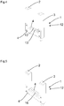
- FIG. 1 shows a fork sensor housing 1 and a fork sensor 12, wherein a transmitter module housing 2 and a receiving module housing 3 are arranged parallel and spaced, wherein the transmitter module housing 2 and the receiving module housing 3 mechanically with at least one mechanical connecting element 4 made of metal are connected, wherein the mechanical connecting element 4 is arranged transversely to the transmitter module housing 2 and transversely to the receiving module housing 3 and at least one electrical connecting element 6 and / or an optical connecting element 7 between the transmitter module housing 2 and the receiving module housing 3 is arranged, whereby a modular U -shaped fork sensor housing 1 is formed.
- the fork sensor 12 may be configured, for example, as a fork light barrier, for example as a through-beam sensor or, for example, as a fork ultrasound sensor.
- the transmitter module housing 2 and the receiver module housing 3 each consist of an outwardly closed independent housing and the internal optoelectronic components of the sensor.
- the mechanical connecting element 4 is designed as a sheet metal part.
- an electrical or optical line or an electrical or optical connection can be provided by means of a connector.
- the transmitter module housing 2 and the receiver module housing 3 are joined in the assembly with the mechanical connection element 4, for example by the sheet metal part to a unit and connected at the interfaces by means of force, form or material connection.
- two mechanical connecting elements 4 are arranged parallel spaced from one another. According to FIG. 1 the mechanical connecting elements 4 are flat.
- FIG. 2 and FIG. 3 each show a fork sensor housing 1 according to FIG. 1 , but in the case of FIG. 2 with a lower fork depth and in the case of FIG. 3 with a smaller fork width than in FIG. 1 shown.
- the mechanical connecting elements 4 according to FIG. 1 and FIG. 2 identical.
- the Transmitter module housing 2 and the receiving module housing 3 according to FIG. 1 and FIG. 3 identical.
- two mechanical connecting elements 4 are connected to each other by means of a positive connection.
- the mechanical connecting elements 4 have a toothing 13. With the teeth 13, the two mechanical connecting elements 4 are connected to each other, so that a stable positive connection is formed. As a result, a closed profile can also be formed by two mechanical connecting elements 4, which increases torsional rigidity.
- the mechanical connecting elements 4 are formed in a connecting portion in cross-section L-shaped. According to FIG. 5 two mechanical connecting elements 4 are connected to each other by means of a material connection, namely, connected to each other by means of a weld 16.
- connection module 8 is arranged on the receiving module housing 3.
- the connection module 8 can also be arranged on the transmitter module housing 2.
- connection module 8 is designed as a line connection.
- connection module has an M12 socket connection.
- connection module has an M8 socket connection.
- the mechanical connecting element 4 is connected to the transmitter module housing 2 and the receiver module housing 3 by means of screw 9.
- the mechanical connecting element 4 is connected to the transmitter module housing 2 and the receiver module housing 3 by means of press-fit connectors 10.
- press-fit connectors 10 all connections can be made in one pressing operation.
- FIG. 11 shows a connection by means of press-in sleeve 11 with hole.
- a hole in the press-fit sleeve 11 can also be used as a mounting hole for mounting the sensor in the application.
- an electrical connection element 6 and / or an optical connection element 7 is provided as a line or as a cable.
- an electrical connection element 6 and / or an optical connection element 7 is provided by means of a connector 17.
- the mechanical connecting elements 4 are U-shaped. According to FIG. 14 the bend is provided on an underside of the mechanical connecting element 4. According to FIG. 15 the bend is provided on an inner side of the mechanical connecting element 4. According to FIG. 16 the bend is provided on an outer side of the mechanical connecting element 4. According to FIG. 17 the bend is provided on an upper side of the mechanical connecting element 4.
Landscapes
- Physics & Mathematics (AREA)
- General Physics & Mathematics (AREA)
- Life Sciences & Earth Sciences (AREA)
- General Life Sciences & Earth Sciences (AREA)
- Geophysics (AREA)
- Arrangements For Transmission Of Measured Signals (AREA)
Abstract
Description
- Die vorliegende Erfindung betrifft ein Gabelsensorgehäuse nach dem Oberbegriff von Anspruch 1 und ein Verfahren zur Montage eines Gabelsensorgehäuses nach dem Oberbegriff von Anspruch 9. Gabelsensoren sind Einweglichtschranken oder Ultraschallsensoren, bei denen Sender und Empfänger in einem U-förmigen Gehäuse integriert sind. Dabei sitzt der Sender in einem der Schenkel, der Empfänger im gegenüberliegenden. Das zu detektierende Tastgut bewegt sich in der Aussparung dazwischen.
- Je nach Anwendung bzw. Applikation werden unterschiedliche Gabelweiten und unterschiedliche Gabeltiefen benötigt, was zu einer hohen Vielfalt an mechanischen Gehäusebauformen führt.
- Bedingt durch die U-förmige Grundgeometrie des Gehäuses neigt die Konstruktion bei mechanischen Beanspruchungen zum Verbiegen bzw. zur Verwindung. Mit steigender Gabelweite und gleichbleibenden Profilabmessungen bzw. Profilquerschnitt, reagiert das Sensorsystem zunehmend empfindlich auf mechanische Deformation des Gehäuses, da der Sendelichtstrahl möglicherweise nicht mehr auf den Empfänger trifft.
- Zum einen gibt es zerspanend hergestellte Metallgehäuse mit Kunststoffdeckeln. Der Gehäusekörper wird spangebend aus Aluminiumhalbzeugen in den benötigten Gabelweiten und Gabeltiefen hergestellt und anschließend lackiert. Zum Abschluss der Gerätemontage werden von der Gabeltiefe abhängende, passgenaue Deckel auf die Gehäuseöffnungen aufgebracht. Hier sind die Herstellkosten aufgrund der Zerspanung relativ hoch.
- Weiter existieren Gehäuse, die aus einem Stück aus Metallguss oder Kunststoffspritzguss hergestellt werden. Hier wird für jede Variante in Gabelweite und Gabeltiefe ein eigenes Werkzeug benötigt. Dafür sind sehr hohe Investitionskosten erforderlich. Weiter entsteht eine umfangreiche Lagerhaltung für eine Bevorratung aller Gehäusevarianten oder es ist nur eine geringe Variantenzahl verfügbar, so dass Kompromisse bei der Anwendung in Kauf genommen werden müssen. Speziell große Gabelweiten sind in Gusstechnologie nur begrenzt herstellbar.
- Gabelsensoren mit Kunststoffgehäuse neigen aufgrund des geringen Elastizitätsmoduls mehr zu Verwindung und sind somit anfällig gegenüber mechanischen Beanspruchungen.
- Eine Aufgabe der Erfindung besteht darin, die oben genannten Nachteile zu vermeiden und einen verbesserten Gabelsensor bzw. ein verbessertes Gabelsensorgehäuse bereitzustellen.
- Die Aufgabe wird gemäß Anspruch 1 gelöst durch ein Gabelsensorgehäuse, wobei ein Sendemodulgehäuse und ein Empfangsmodulgehäuse parallel und beabstandet angeordnet sind, wobei das Sendemodulgehäuse und das Empfangsmodulgehäuse mechanisch mit mindestens einem mechanischen Verbindungselement aus Metall verbunden sind, wobei das mechanische Verbindungselement quer zu dem Sendemodulgehäuse und quer zu dem Empfangsmodulgehäuse angeordnet ist und mindestens ein elektrisches Verbindungselement und/oder ein optisches Verbindungselement zwischen dem Sendemodulgehäuse und dem Empfangsmodulgehäuse angeordnet ist, wodurch ein modular aufgebautes U-förmiges Gabelsensorgehäuse gebildet ist.
- Die Aufgabe wird weiter gelöst durch ein Verfahren zur Montage eines Gabelsensorgehäuse, wobei ein Sendemodulgehäuse und ein Empfangsmodulgehäuse parallel und beabstandet angeordnet werden, wobei das Sendemodulgehäuse und das Empfangsmodulgehäuse mechanisch mit mindestens einem mechanischen Verbindungselement aus Metall verbunden wird, wobei das mechanische Verbindungselement quer zu dem Sendemodulgehäuse und quer zu dem Empfangsmodulgehäuse angeordnet wird, und mindestens ein elektrisches Verbindungselement und/oder ein optisches Verbindungselement zwischen dem Sendemodulgehäuse und dem Empfangsmodulgehäuse angeordnet wird, wodurch ein modular aufgebautes U-förmiges Gabelsensorgehäuse gebildet wird.
- Gemäß der Erfindung sind unterschiedliche Sendemodulgehäuse, unterschiedliche Empfangsmodulgehäuse, unterschiedliche mechanische Verbindungselemente, unterschiedliche elektrische Verbindungselemente und unterschiedliche optische Verbindungselemente vorgesehen, die jeweils miteinander kombinierbar sind.
- Gemäß der Erfindung ist ein modularer Gehäuseaufbau bereitgestellt. Durch eine geringe Anzahl von Bauteilen oder Elementen kann eine große Varianz an Endgeräten erzeugt werden. Das Baukastensystem erlaubt eine einfache Erzeugung neuer Gerätevarianten in der Konstruktion. Weiter ist eine späte Variantenbildung möglich durch eine Montage weniger Module in einer Endmontage in der Produktion. Weiter sind die Werkzeuginitialkosten bei dem Baukastensystem gering. Weiter liegt eine geringe Lagerhaltung bei dem Baukastensystem vor.
- Das Gabelsensorgehäuse wird in einer Endmontage aus mehreren Komponenten zusammengesetzt. Dabei werden für jede Gabeltiefe ein Sendemodulgehäuse und ein Empfangsmodulgehäuse benötigt. Für diese Module ist die Gabelweite nicht relevant. Das Sendemodulgehäuse und das Empfangsmodulgehäuse bestehen jeweils aus einem nach außen geschlossenem Gehäuse und den innen liegenden optoelektronischen Komponenten des Sensors.
- Die für die Modulgehäuse benötigten Komponenten sind als werkzeuggebundene Kunststoff-Spritzgussteile ausgeführt. Die Kunststoffgehäuse können einfach aus eingefärbtem Kunststoff hergestellt werden, wodurch eine kostengünstigere Farbgebung gegenüber einer Lackierung von Metallteilen möglich ist.
- Zur Verbindung der zwei Modulgehäuse werden für jede Gabelweite mindestens ein mechanisches und mindestens ein elektrisches bzw. optisches Verbindungselement benötigt, um beispielsweise eine Stromversorgung oder eine Kommunikationsverbindung im Falle des elektrischen Verbindungselements zu ermöglichen. Das optische Verbindungselement ist für eine Kommunikationsverbindung vorgesehen.
- Das mechanische Verbindungselement ist beispielsweise als Blechbiegeteil ausgeführt. Dieses kann für große Stückzahlen werkzeuggebunden in einem Stanz-Biege-Werkzeug hergestellt werden oder für kleine Stückzahlen CNC-gelasert oder CNC-gebogen werden.
- Die elektrische bzw. optische Verbindung kann vorkonfektioniert oder im Montageablauf auf die benötigte Gabelweite abgelängt werden. Es kann dabei eine elektrische oder optische Leitung oder eine elektrische oder optische Verbindung mittels eines Steckverbinders vorgesehen werden.
- Das Sende- und Empfangsmodulgehäuse werden in der Montage mit dem mechanischen Verbindungselement, beispielsweise durch das Blechbiegeteil zu einer Einheit gefügt und an den Schnittstellen mittels Kraft-, Form- oder Stoffschluss verbunden.
- Die werkzeuggebundene Herstellung der Einzelteile führt zu einer Kosteneinsparung gegenüber spangebenden Verfahren oder einer Vorbaugruppenmontage.
- In Weiterbildung der Erfindung sind zwei mechanische Verbindungselemente parallel beabstandet zueinander angeordnet. Dadurch wird das Gabelsensorgehäuse stabiler ausgeführt und eine Verwindungssteifigkeit erhöht. Die mechanischen Verbindungselemente können dabei auch in einem Verbindungsabschnitt im Querschnitt L-förmig ausgebildet sein, wodurch die Elemente stabiler ausgebildet sind.
- Bevorzugt sind die mechanischen Verbindungselemente flach ausgebildet. Dadurch können die mechanischen Verbindungselemente sehr einfach und preiswert als Stanzteile hergestellt werden.
- In Weiterbildung der Erfindung sind mindestens zwei mechanische Verbindungselemente mittels eines Formschlusses miteinander verbunden, beispielsweise weisen die Verbindungselemente eine Verzahnung auf. Mit der Verzahnung sind jeweils zwei mechanische Verbindungselemente miteinander verbindbar, so dass ein stabiler Formschluss entsteht. Dadurch wird weiter auch ein geschlossenes Profil durch zwei mechanische Verbindungselemente gebildet, wodurch eine Verwindungssteifigkeit erhöht wird.
- In Weiterbildung der Erfindung sind mindestens zwei mechanische Verbindungselemente mittels eines Stoffschlusses miteinander verbunden, beispielsweise mittels einer Schweißnaht miteinander verbunden. Mit dieser Maßnahme kann eine zu massiven Metallgehäusen vergleichbare Verwindungssteifigkeit erzielt werden.
- In Weiterbildung der Erfindung ist das mechanische Verbindungselement U-förmig ausgebildet, wodurch eine Stabilität und Verwindungssteifigkeit erhöht wird. Das U-förmige Verbindungselement wird beispielsweise durch Biegung erzeugt. Die Biegungen können dabei an einer Unterseite, an einer Innenseite, an einer Außenseite oder an einer Oberseite vorgesehen sein.
- In Weiterbildung der Erfindung ist am Sendermodulgehäuse oder am Empfangsmodulgehäuse ein Anschlussmodul angeordnet. Das Anschlussmodul kann dabei unterschiedlich ausgebildet sein, wodurch ebenfalls eine modulare Gestaltung der Anschlusstechnik vorliegt. Bei dem Anschlussmodul kann es sich beispielsweise um einen modularen Leitungsanschluss, um einen modularen M12 Buchsenanschluss oder um einen modularen M8 Buchsenanschluss handeln.
- Gemäß einer Weiterbildung der Erfindung ist das mechanische Verbindungselement mit dem Sendemodulgehäuse und dem Empfangsmodulgehäuse mittels Verschraubung, mittels Einpressverbinder und/oder mittels Einpresshülse mit Loch verbunden. Bei Verwendung von Einpressverbindern können in einem Pressvorgang alle Verbindungen hergestellt werden. Bei einer Ausführung mit Einpresshülse kann ein Loch in der Einpresshülse auch als Befestigungsbohrung für die Anbringung des Sensors in der Applikation genutzt werden.
- Die Erfindung wird nachstehend auch hinsichtlich weiterer Vorteile und Merkmale unter Bezugnahme auf die beigefügte Zeichnung anhand von Ausführungsbeispielen erläutert. Die Figuren der Zeichnung zeigen in:
- Figur 1 bis 18
- jeweils verschiedene Ausführungsformen eines Gabelsensorgehäuses bzw. eines Gabelsensors und Verfahren zur Montage eines Gabelsensorgehäuses bzw. eines Gabelsensors.
- In den nachfolgenden Figuren sind identische Teile mit identischen Bezugszeichen versehen.
-
Figur 1 zeigt ein Gabelsensorgehäuse 1 bzw. einen Gabelsensor 12, wobei ein Sendemodulgehäuse 2 und ein Empfangsmodulgehäuse 3 parallel und beabstandet angeordnet sind, wobei das Sendemodulgehäuse 2 und das Empfangsmodulgehäuse 3 mechanisch mit mindestens einem mechanischen Verbindungselement 4 aus Metall verbunden sind, wobei das mechanische Verbindungselement 4 quer zu dem Sendemodulgehäuse 2 und quer zu dem Empfangsmodulgehäuse 3 angeordnet ist und mindestens ein elektrisches Verbindungselement 6 und/oder ein optisches Verbindungselement 7 zwischen dem Sendemodulgehäuse 2 und dem Empfangsmodulgehäuse 3 angeordnet ist, wodurch ein modular aufgebautes U-förmiges Gabelsensorgehäuse 1 gebildet ist. - Der Gabelsensor 12 kann beispielsweise als Gabellichtschranke, beispielsweise als Einweglichtschranke oder beispielsweise als Gabelultraschallsensor ausgebildet sein.
- Das Sendemodulgehäuse 2 und das Empfangsmodulgehäuse 3 bestehen jeweils aus einem nach außen geschlossenem eigenständigen Gehäuse und den innenliegenden optoelektronischen Komponenten des Sensors.
- Zur Verbindung der zwei Modulgehäuse 2 und 3 sind zwei mechanische Verbindungselemente 4 und ein elektrisches Verbindungselement 6 bzw. ein optisches Verbindungselement 7 angeordnet. Das mechanische Verbindungselement 4 ist als Blechteil ausgeführt.
- Bei der elektrischen bzw. optischen Verbindung kann eine elektrische oder optische Leitung oder eine elektrische oder optische Verbindung mittels eines Steckverbinders vorgesehen werden.
- Das Sendemodulgehäuse 2 und das Empfangsmodulgehäuse 3 werden in der Montage mit dem mechanisches Verbindungselement 4, beispielsweise durch das Blechteil zu einer Einheit gefügt und an den Schnittstellen mittels Kraft-, Form- oder Stoffschluss verbunden.
- Gemäß
Figur 1 sind zwei mechanische Verbindungselemente 4 parallel beabstandet zueinander angeordnet. GemäßFigur 1 sind die mechanischen Verbindungselemente 4 flach ausgebildet. -
Figur 2 und Figur 3 zeigen jeweils ein Gabelsensorgehäuse 1 gemäßFigur 1 , jedoch im Fall vonFigur 2 mit einer geringeren Gabeltiefe und im Fall vonFigur 3 mit einer geringeren Gabelweite als inFigur 1 dargestellt. Dabei sind die mechanischen Verbindungselemente 4 gemäßFigur 1 und Figur 2 identisch. Weiter sind die Sendemodulgehäuse 2 und die Empfangsmodulgehäuse 3 gemäßFigur 1 und Figur 3 identisch. - Gemäß
Figur 4 sind zwei mechanische Verbindungselemente 4 mittels eines Formschlusses miteinander verbunden. Die mechanischen Verbindungselemente 4 weisen eine Verzahnung 13 auf. Mit der Verzahnung 13 sind die zwei mechanischen Verbindungselemente 4 miteinander verbunden, so dass ein stabiler Formschluss entsteht. Dadurch kann weiter auch ein geschlossenes Profil durch zwei mechanische Verbindungselemente 4 gebildet werden, wodurch eine Verwindungssteifigkeit erhöht wird. - Gemäß
Figur 5 sind die mechanischen Verbindungselemente 4 in einem Verbindungsabschnitt im Querschnitt L-förmig ausgebildet sein. GemäßFigur 5 sind zwei mechanische Verbindungselemente 4 mittels eines Stoffschlusses miteinander verbunden, nämlich mittels einer Schweißnaht 16 miteinander verbunden. - Gemäß
Figur 6 ist am Empfangsmodulgehäuse 3 ein Anschlussmodul 8 angeordnet. Jedoch kann das Anschlussmodul 8 auch am Sendermodulgehäuse 2 angeordnet sein. - Gemäß
Figur 6 ist das Anschlussmodul 8 als Leitungsanschluss ausgebildet. GemäßFigur 7 weist das Anschlussmodul einen M12 Buchsenanschluss auf. GemäßFigur 8 weist das Anschlussmodul einen M8 Buchsenanschluss auf. - Gemäß
Figur 9 ist das mechanische Verbindungselement 4 mit dem Sendemodulgehäuse 2 und dem Empfangsmodulgehäuse 3 mittels Verschraubung 9 verbunden. - Gemäß
Figur 10 ist das mechanische Verbindungselement 4 mit dem Sendemodulgehäuse 2 und dem Empfangsmodulgehäuse 3 mittels Einpressverbinder 10 verbunden. Bei Verwendung von Einpressverbindern 10 können in einem Pressvorgang alle Verbindungen hergestellt werden. -
Figur 11 zeigt eine Verbindung mittels Einpresshülse 11 mit Loch. Bei der Ausführung mit Einpresshülse 11 kann ein Loch in der Einpresshülse 11 auch als Befestigungsbohrung für die Anbringung des Sensors in der Applikation genutzt werden. - Gemäß
Figur 12 ist eine elektrisches Verbindungselement 6 und/oder ein optisches Verbindungselement 7 als Leitung bzw. als Kabel vorgesehen. - Gemäß
Figur 13 ist ein elektrisches Verbindungselement 6 und/oder ein optisches Verbindungselement 7 mittels eines Steckverbinders 17 vorgesehen. - Gemäß den
Figuren 14 bis 17 sind die mechanischen Verbindungselemente 4 U-förmig ausgebildet. GemäßFigur 14 ist die Biegung an einer Unterseite des mechanischen Verbindungselementes 4 vorgesehen. GemäßFigur 15 ist die Biegung an einer Innenseite des mechanischen Verbindungselementes 4 vorgesehen. GemäßFigur 16 ist die Biegung an einer Außenseite des mechanischen Verbindungselementes 4 vorgesehen. GemäßFigur 17 ist die Biegung an einer Oberseite des mechanischen Verbindungselementes 4 vorgesehen. -
- 1 Gabelsensorgehäuse
- 2 Sendemodulgehäuse
- 3 Empfangsmodulgehäuse
- 4 mechanisches Verbindungselement
- 6 elektrisches Verbindungselement
- 7 optisches Verbindungselement
- 8 Anschlussmodul
- 9 Verschraubung
- 10 Einpressverbinder
- 11 Einpresshülse
- 12 Gabelsensor
- 13 Verzahnung
- 14 Leitungsanschluss
- 15 Buchsenanschluss
- 16 Schweißnaht
- 17 Steckverbinder
Claims (16)
- Gabelsensorgehäuse (1),
dadurch gekennzeichnet, dass
ein Sendemodulgehäuse (2) und ein Empfangsmodulgehäuse (3) parallel und beabstandet angeordnet sind,
wobei das Sendemodulgehäuse (2) und das Empfangsmodulgehäuse (3) mechanisch mit mindestens einem mechanischen Verbindungselement (4) aus Metall verbunden sind,
wobei das mechanische Verbindungselement (4) quer zu dem Sendemodulgehäuse (2) und quer zu dem Empfangsmodulgehäuse (3) angeordnet ist,
und mindestens ein elektrisches Verbindungselement (6) und/oder ein optisches Verbindungselement (7) zwischen dem Sendemodulgehäuse (2) und dem Empfangsmodulgehäuse (3) angeordnet ist,
wodurch ein modular aufgebautes U-förmiges Gabelsensorgehäuse (1) gebildet ist. - Gabelsensorgehäuse (1) nach Anspruch 1, dadurch gekennzeichnet, dass zwei mechanische Verbindungselemente (4) parallel beabstandet zueinander angeordnet sind.
- Gabelsensorgehäuse (1) nach Anspruch 2, dadurch gekennzeichnet, dass die mechanischen Verbindungselemente (4) flach ausgebildet sind.
- Gabelsensorgehäuse (1) nach mindestens einem der vorgenannten Ansprüche, dadurch gekennzeichnet, dass mindestens zwei mechanische Verbindungselemente (4) mittels eines Formschlusses miteinander verbunden sind.
- Gabelsensorgehäuse (1) nach mindestens einem der vorgenannten Ansprüche, dadurch gekennzeichnet, dass mindestens zwei mechanische Verbindungselemente (4) mittels eines Stoffschlusses miteinander verbunden sind.
- Gabelsensorgehäuse (1) nach Anspruch 1, dadurch gekennzeichnet, dass das mechanische Verbindungselement (4) U-förmig ausgebildet ist.
- Gabelsensorgehäuse (1) nach mindestens einem der vorgenannten Ansprüche, dadurch gekennzeichnet, dass am Sendemodulgehäuse (2) oder am Empfangsmodulgehäuse (3) ein Anschlussmodul (8) angeordnet ist.
- Gabelsensorgehäuse (1) nach mindestens einem der vorgenannten Ansprüche, dadurch gekennzeichnet, dass das mechanische Verbindungselement (4) mit dem Sendemodulgehäuse (2) und dem Empfangsmodulgehäuse (3) mittels Verschraubung (9), mittels Einpressverbinder (10) und/oder mittels Einpresshülse (11) mit Loch verbunden ist.
- Verfahren zur Montage eines Gabelsensorgehäuse (1),
dadurch gekennzeichnet, dass
ein Sendemodulgehäuse (2) und ein Empfangsmodulgehäuse (3) parallel und beabstandet angeordnet werden,
wobei das Sendemodulgehäuse (2) und das Empfangsmodulgehäuse (3) mechanisch mit mindestens einem mechanischen Verbindungselement (4) aus Metall verbunden werden,
wobei das mechanische Verbindungselement (4) quer zu dem Sendemodulgehäuse (2) und quer zu dem Empfangsmodulgehäuse (3) angeordnet wird,
und mindestens ein elektrisches Verbindungselement (6) und/oder ein optisches Verbindungselement (7) zwischen dem Sendemodulgehäuse (2) und dem Empfangsmodulgehäuse (3) angeordnet wird,
wodurch ein modular aufgebautes U-förmiges Gabelsensorgehäuse (1) gebildet wird. - Verfahren nach Anspruch 9, dadurch gekennzeichnet, dass zwei mechanische Verbindungselemente (4) parallel beabstandet zueinander angeordnet werden.
- Gabelsensorgehäuse (1) nach Anspruch 10, dadurch gekennzeichnet, dass die mechanischen Verbindungselemente (4) flach ausgebildet werden.
- Gabelsensorgehäuse (1) nach mindestens einem der vorgenannten Ansprüche 9 bis 11, dadurch gekennzeichnet, dass mindestens zwei mechanische Verbindungselemente (4) formschlüssig miteinander verbunden werden.
- Gabelsensorgehäuse (1) nach mindestens einem der vorgenannten Ansprüche 9 bis 12, dadurch gekennzeichnet, dass mindestens zwei mechanische Verbindungselemente (4) stoffschlüssig miteinander verbunden werden.
- Gabelsensorgehäuse (1) nach Anspruch 9, dadurch gekennzeichnet, dass das mechanische Verbindungselement (4) U-förmig ausgebildet wird.
- Gabelsensorgehäuse (1) nach mindestens einem der vorgenannten Ansprüche 9 bis 14, dadurch gekennzeichnet, dass am Sendemodulgehäuse (2) oder am Empfangsmodulgehäuse (3) ein Anschlussmodul (8) angeordnet wird.
- Gabelsensorgehäuse (1) nach mindestens einem der vorgenannten Ansprüche 9 bis 15, dadurch gekennzeichnet, dass das mechanische Verbindungselement (4) mit dem Sendemodulgehäuse (2) und dem Empfangsmodulgehäuse (3) mittels Verschraubung (9), mittels Einpressverbinder (10) und/oder mittels Einpresshülse (11) mit Loch verbunden wird.
Priority Applications (1)
| Application Number | Priority Date | Filing Date | Title |
|---|---|---|---|
| EP18150960.5A EP3511682B1 (de) | 2018-01-10 | 2018-01-10 | Gabelsensorgehäuse |
Applications Claiming Priority (1)
| Application Number | Priority Date | Filing Date | Title |
|---|---|---|---|
| EP18150960.5A EP3511682B1 (de) | 2018-01-10 | 2018-01-10 | Gabelsensorgehäuse |
Publications (2)
| Publication Number | Publication Date |
|---|---|
| EP3511682A1 true EP3511682A1 (de) | 2019-07-17 |
| EP3511682B1 EP3511682B1 (de) | 2020-06-03 |
Family
ID=60972022
Family Applications (1)
| Application Number | Title | Priority Date | Filing Date |
|---|---|---|---|
| EP18150960.5A Active EP3511682B1 (de) | 2018-01-10 | 2018-01-10 | Gabelsensorgehäuse |
Country Status (1)
| Country | Link |
|---|---|
| EP (1) | EP3511682B1 (de) |
Citations (4)
| Publication number | Priority date | Publication date | Assignee | Title |
|---|---|---|---|---|
| DE3008309A1 (de) * | 1980-03-04 | 1981-09-10 | Siemens AG, 1000 Berlin und 8000 München | Lichtschranke zur erfassung mechanischer bewegungen |
| US5672886A (en) * | 1994-08-12 | 1997-09-30 | Kabushiki Kaisha Toshiba | Surface inspection system for detecting various surface faults |
| DE102005059859A1 (de) * | 2005-12-15 | 2007-06-28 | Sensopart Industriesensorik Gmbh | Lichtschranke |
| DE202007002864U1 (de) * | 2007-02-27 | 2007-07-05 | Pepperl + Fuchs Gmbh | Gabelgehäuse, insbesondere für Licht- oder Ultraschallschranken |
-
2018
- 2018-01-10 EP EP18150960.5A patent/EP3511682B1/de active Active
Patent Citations (4)
| Publication number | Priority date | Publication date | Assignee | Title |
|---|---|---|---|---|
| DE3008309A1 (de) * | 1980-03-04 | 1981-09-10 | Siemens AG, 1000 Berlin und 8000 München | Lichtschranke zur erfassung mechanischer bewegungen |
| US5672886A (en) * | 1994-08-12 | 1997-09-30 | Kabushiki Kaisha Toshiba | Surface inspection system for detecting various surface faults |
| DE102005059859A1 (de) * | 2005-12-15 | 2007-06-28 | Sensopart Industriesensorik Gmbh | Lichtschranke |
| DE202007002864U1 (de) * | 2007-02-27 | 2007-07-05 | Pepperl + Fuchs Gmbh | Gabelgehäuse, insbesondere für Licht- oder Ultraschallschranken |
Also Published As
| Publication number | Publication date |
|---|---|
| EP3511682B1 (de) | 2020-06-03 |
Similar Documents
| Publication | Publication Date | Title |
|---|---|---|
| EP2084787B1 (de) | Gesicherte steckverbindung und verfahren zu ihrer herstellung | |
| DE102008036399A1 (de) | Datenkabel | |
| DE19936300A1 (de) | Druckerkennungsvorrichtung, Verbindungsteil hierfür, sowie Verfahren zur Herstellung eines elektrischen Bauteileverbinders | |
| EP3552463B1 (de) | Leiterplattenverbund und verfahren zu dessen herstellung | |
| EP2470868B1 (de) | Anschlussanordnung für eine sensoranordnung und sensoranordnung | |
| EP1890162A2 (de) | Elektrische Mess-Vorrichtung | |
| DE102012213234A1 (de) | Verstellantrieb | |
| DE102012203946A1 (de) | Elektrische Maschine zum motorischen Verstellen beweglicher Teile im Kraftfahrzeug, sowie Verfahren zum Herstellen der elektrischen Maschine | |
| DE102008051545A1 (de) | Elektronisches Gerät mit Mehrkontaktstecker und Verfahren zur Herstellung desselben | |
| DE102015103551A1 (de) | Steckerbaugruppe für einen Sensor und Verfahren zur Montage einer Steckerbaugruppe für einen Sensor | |
| WO2011045228A2 (de) | Adapterplatte zur befestigung eines gehäuses in einem fahrzeug und korrespondierendes steuergerät | |
| EP2797176B1 (de) | Sensoreinheit | |
| DE102012205969A1 (de) | Sensorvorrichtung | |
| DE102023200308A1 (de) | Sensorbaugruppe für ein Fahrzeug | |
| WO1998028960A1 (de) | Elektrisches gerät | |
| EP3511682B1 (de) | Gabelsensorgehäuse | |
| DE19825727A1 (de) | Drosselklappenstutzen | |
| DE102010031304A1 (de) | Kabelknickschutzeinheit und Verfahren zur Herstellung derselben | |
| DE102017128755A1 (de) | Elektrisches Steckverbinderteil sowie Verfahren zum Herstellen eines solchen elektrischen Steckverbinderteils | |
| DE102004058715B4 (de) | Kraftstoffinjektor für eine Brennkraftmaschine sowie Verfahren zur Herstellung eines Kraftstoffinjektors | |
| EP2026418B1 (de) | Gehäuseschale mit eingeschlossener, mindestens ein elektromechanisches Bauelement aufweisenden Baueinheit | |
| DE102017206623A1 (de) | Bürstenhalter für eine elektrische Kommutatormaschine | |
| DE29718790U1 (de) | Drehwertgeber | |
| DE10316384A1 (de) | Kontaktadapter für die Kontaktierung einer Antennenstruktur eines Fahrzeuges | |
| DE102005024196B4 (de) | Kraftstoffinjektor für eine Brennkraftmaschine sowie Verfahren zur Montage eines derartigen Kraftstoffinjektors |
Legal Events
| Date | Code | Title | Description |
|---|---|---|---|
| PUAI | Public reference made under article 153(3) epc to a published international application that has entered the european phase |
Free format text: ORIGINAL CODE: 0009012 |
|
| STAA | Information on the status of an ep patent application or granted ep patent |
Free format text: STATUS: THE APPLICATION HAS BEEN PUBLISHED |
|
| AK | Designated contracting states |
Kind code of ref document: A1 Designated state(s): AL AT BE BG CH CY CZ DE DK EE ES FI FR GB GR HR HU IE IS IT LI LT LU LV MC MK MT NL NO PL PT RO RS SE SI SK SM TR |
|
| AX | Request for extension of the european patent |
Extension state: BA ME |
|
| STAA | Information on the status of an ep patent application or granted ep patent |
Free format text: STATUS: REQUEST FOR EXAMINATION WAS MADE |
|
| 17P | Request for examination filed |
Effective date: 20191111 |
|
| GRAP | Despatch of communication of intention to grant a patent |
Free format text: ORIGINAL CODE: EPIDOSNIGR1 |
|
| STAA | Information on the status of an ep patent application or granted ep patent |
Free format text: STATUS: GRANT OF PATENT IS INTENDED |
|
| RAP1 | Party data changed (applicant data changed or rights of an application transferred) |
Owner name: SICK AG |
|
| RBV | Designated contracting states (corrected) |
Designated state(s): AL AT BE BG CH CY CZ DE DK EE ES FI FR GB GR HR HU IE IS IT LI LT LU LV MC MK MT NL NO PL PT RO RS SE SI SK SM TR |
|
| INTG | Intention to grant announced |
Effective date: 20200214 |
|
| GRAS | Grant fee paid |
Free format text: ORIGINAL CODE: EPIDOSNIGR3 |
|
| GRAA | (expected) grant |
Free format text: ORIGINAL CODE: 0009210 |
|
| STAA | Information on the status of an ep patent application or granted ep patent |
Free format text: STATUS: THE PATENT HAS BEEN GRANTED |
|
| AK | Designated contracting states |
Kind code of ref document: B1 Designated state(s): AL AT BE BG CH CY CZ DE DK EE ES FI FR GB GR HR HU IE IS IT LI LT LU LV MC MK MT NL NO PL PT RO RS SE SI SK SM TR |
|
| REG | Reference to a national code |
Ref country code: GB Ref legal event code: FG4D Free format text: NOT ENGLISH |
|
| REG | Reference to a national code |
Ref country code: AT Ref legal event code: REF Ref document number: 1277476 Country of ref document: AT Kind code of ref document: T Effective date: 20200615 Ref country code: CH Ref legal event code: EP |
|
| REG | Reference to a national code |
Ref country code: DE Ref legal event code: R096 Ref document number: 502018001550 Country of ref document: DE |
|
| REG | Reference to a national code |
Ref country code: LT Ref legal event code: MG4D |
|
| PG25 | Lapsed in a contracting state [announced via postgrant information from national office to epo] |
Ref country code: SE Free format text: LAPSE BECAUSE OF FAILURE TO SUBMIT A TRANSLATION OF THE DESCRIPTION OR TO PAY THE FEE WITHIN THE PRESCRIBED TIME-LIMIT Effective date: 20200603 Ref country code: LT Free format text: LAPSE BECAUSE OF FAILURE TO SUBMIT A TRANSLATION OF THE DESCRIPTION OR TO PAY THE FEE WITHIN THE PRESCRIBED TIME-LIMIT Effective date: 20200603 Ref country code: NO Free format text: LAPSE BECAUSE OF FAILURE TO SUBMIT A TRANSLATION OF THE DESCRIPTION OR TO PAY THE FEE WITHIN THE PRESCRIBED TIME-LIMIT Effective date: 20200903 Ref country code: FI Free format text: LAPSE BECAUSE OF FAILURE TO SUBMIT A TRANSLATION OF THE DESCRIPTION OR TO PAY THE FEE WITHIN THE PRESCRIBED TIME-LIMIT Effective date: 20200603 Ref country code: GR Free format text: LAPSE BECAUSE OF FAILURE TO SUBMIT A TRANSLATION OF THE DESCRIPTION OR TO PAY THE FEE WITHIN THE PRESCRIBED TIME-LIMIT Effective date: 20200904 |
|
| REG | Reference to a national code |
Ref country code: NL Ref legal event code: MP Effective date: 20200603 |
|
| PG25 | Lapsed in a contracting state [announced via postgrant information from national office to epo] |
Ref country code: BG Free format text: LAPSE BECAUSE OF FAILURE TO SUBMIT A TRANSLATION OF THE DESCRIPTION OR TO PAY THE FEE WITHIN THE PRESCRIBED TIME-LIMIT Effective date: 20200903 Ref country code: RS Free format text: LAPSE BECAUSE OF FAILURE TO SUBMIT A TRANSLATION OF THE DESCRIPTION OR TO PAY THE FEE WITHIN THE PRESCRIBED TIME-LIMIT Effective date: 20200603 Ref country code: LV Free format text: LAPSE BECAUSE OF FAILURE TO SUBMIT A TRANSLATION OF THE DESCRIPTION OR TO PAY THE FEE WITHIN THE PRESCRIBED TIME-LIMIT Effective date: 20200603 Ref country code: HR Free format text: LAPSE BECAUSE OF FAILURE TO SUBMIT A TRANSLATION OF THE DESCRIPTION OR TO PAY THE FEE WITHIN THE PRESCRIBED TIME-LIMIT Effective date: 20200603 |
|
| PG25 | Lapsed in a contracting state [announced via postgrant information from national office to epo] |
Ref country code: NL Free format text: LAPSE BECAUSE OF FAILURE TO SUBMIT A TRANSLATION OF THE DESCRIPTION OR TO PAY THE FEE WITHIN THE PRESCRIBED TIME-LIMIT Effective date: 20200603 Ref country code: AL Free format text: LAPSE BECAUSE OF FAILURE TO SUBMIT A TRANSLATION OF THE DESCRIPTION OR TO PAY THE FEE WITHIN THE PRESCRIBED TIME-LIMIT Effective date: 20200603 |
|
| PG25 | Lapsed in a contracting state [announced via postgrant information from national office to epo] |
Ref country code: CZ Free format text: LAPSE BECAUSE OF FAILURE TO SUBMIT A TRANSLATION OF THE DESCRIPTION OR TO PAY THE FEE WITHIN THE PRESCRIBED TIME-LIMIT Effective date: 20200603 Ref country code: ES Free format text: LAPSE BECAUSE OF FAILURE TO SUBMIT A TRANSLATION OF THE DESCRIPTION OR TO PAY THE FEE WITHIN THE PRESCRIBED TIME-LIMIT Effective date: 20200603 Ref country code: IT Free format text: LAPSE BECAUSE OF FAILURE TO SUBMIT A TRANSLATION OF THE DESCRIPTION OR TO PAY THE FEE WITHIN THE PRESCRIBED TIME-LIMIT Effective date: 20200603 Ref country code: SM Free format text: LAPSE BECAUSE OF FAILURE TO SUBMIT A TRANSLATION OF THE DESCRIPTION OR TO PAY THE FEE WITHIN THE PRESCRIBED TIME-LIMIT Effective date: 20200603 Ref country code: EE Free format text: LAPSE BECAUSE OF FAILURE TO SUBMIT A TRANSLATION OF THE DESCRIPTION OR TO PAY THE FEE WITHIN THE PRESCRIBED TIME-LIMIT Effective date: 20200603 Ref country code: RO Free format text: LAPSE BECAUSE OF FAILURE TO SUBMIT A TRANSLATION OF THE DESCRIPTION OR TO PAY THE FEE WITHIN THE PRESCRIBED TIME-LIMIT Effective date: 20200603 Ref country code: PT Free format text: LAPSE BECAUSE OF FAILURE TO SUBMIT A TRANSLATION OF THE DESCRIPTION OR TO PAY THE FEE WITHIN THE PRESCRIBED TIME-LIMIT Effective date: 20201006 |
|
| PG25 | Lapsed in a contracting state [announced via postgrant information from national office to epo] |
Ref country code: IS Free format text: LAPSE BECAUSE OF FAILURE TO SUBMIT A TRANSLATION OF THE DESCRIPTION OR TO PAY THE FEE WITHIN THE PRESCRIBED TIME-LIMIT Effective date: 20201003 Ref country code: PL Free format text: LAPSE BECAUSE OF FAILURE TO SUBMIT A TRANSLATION OF THE DESCRIPTION OR TO PAY THE FEE WITHIN THE PRESCRIBED TIME-LIMIT Effective date: 20200603 Ref country code: SK Free format text: LAPSE BECAUSE OF FAILURE TO SUBMIT A TRANSLATION OF THE DESCRIPTION OR TO PAY THE FEE WITHIN THE PRESCRIBED TIME-LIMIT Effective date: 20200603 |
|
| REG | Reference to a national code |
Ref country code: DE Ref legal event code: R097 Ref document number: 502018001550 Country of ref document: DE |
|
| PLBE | No opposition filed within time limit |
Free format text: ORIGINAL CODE: 0009261 |
|
| STAA | Information on the status of an ep patent application or granted ep patent |
Free format text: STATUS: NO OPPOSITION FILED WITHIN TIME LIMIT |
|
| PG25 | Lapsed in a contracting state [announced via postgrant information from national office to epo] |
Ref country code: DK Free format text: LAPSE BECAUSE OF FAILURE TO SUBMIT A TRANSLATION OF THE DESCRIPTION OR TO PAY THE FEE WITHIN THE PRESCRIBED TIME-LIMIT Effective date: 20200603 |
|
| 26N | No opposition filed |
Effective date: 20210304 |
|
| PG25 | Lapsed in a contracting state [announced via postgrant information from national office to epo] |
Ref country code: SI Free format text: LAPSE BECAUSE OF FAILURE TO SUBMIT A TRANSLATION OF THE DESCRIPTION OR TO PAY THE FEE WITHIN THE PRESCRIBED TIME-LIMIT Effective date: 20200603 |
|
| PG25 | Lapsed in a contracting state [announced via postgrant information from national office to epo] |
Ref country code: MC Free format text: LAPSE BECAUSE OF FAILURE TO SUBMIT A TRANSLATION OF THE DESCRIPTION OR TO PAY THE FEE WITHIN THE PRESCRIBED TIME-LIMIT Effective date: 20200603 |
|
| PG25 | Lapsed in a contracting state [announced via postgrant information from national office to epo] |
Ref country code: LU Free format text: LAPSE BECAUSE OF NON-PAYMENT OF DUE FEES Effective date: 20210110 |
|
| REG | Reference to a national code |
Ref country code: BE Ref legal event code: MM Effective date: 20210131 |
|
| PG25 | Lapsed in a contracting state [announced via postgrant information from national office to epo] |
Ref country code: IE Free format text: LAPSE BECAUSE OF NON-PAYMENT OF DUE FEES Effective date: 20210110 |
|
| PG25 | Lapsed in a contracting state [announced via postgrant information from national office to epo] |
Ref country code: BE Free format text: LAPSE BECAUSE OF NON-PAYMENT OF DUE FEES Effective date: 20210131 |
|
| GBPC | Gb: european patent ceased through non-payment of renewal fee |
Effective date: 20220110 |
|
| PG25 | Lapsed in a contracting state [announced via postgrant information from national office to epo] |
Ref country code: GB Free format text: LAPSE BECAUSE OF NON-PAYMENT OF DUE FEES Effective date: 20220110 |
|
| PG25 | Lapsed in a contracting state [announced via postgrant information from national office to epo] |
Ref country code: CY Free format text: LAPSE BECAUSE OF FAILURE TO SUBMIT A TRANSLATION OF THE DESCRIPTION OR TO PAY THE FEE WITHIN THE PRESCRIBED TIME-LIMIT Effective date: 20200603 |
|
| PG25 | Lapsed in a contracting state [announced via postgrant information from national office to epo] |
Ref country code: HU Free format text: LAPSE BECAUSE OF FAILURE TO SUBMIT A TRANSLATION OF THE DESCRIPTION OR TO PAY THE FEE WITHIN THE PRESCRIBED TIME-LIMIT; INVALID AB INITIO Effective date: 20180110 |
|
| REG | Reference to a national code |
Ref country code: AT Ref legal event code: MM01 Ref document number: 1277476 Country of ref document: AT Kind code of ref document: T Effective date: 20230110 |
|
| PG25 | Lapsed in a contracting state [announced via postgrant information from national office to epo] |
Ref country code: AT Free format text: LAPSE BECAUSE OF NON-PAYMENT OF DUE FEES Effective date: 20230110 |
|
| PG25 | Lapsed in a contracting state [announced via postgrant information from national office to epo] |
Ref country code: MK Free format text: LAPSE BECAUSE OF FAILURE TO SUBMIT A TRANSLATION OF THE DESCRIPTION OR TO PAY THE FEE WITHIN THE PRESCRIBED TIME-LIMIT Effective date: 20200603 Ref country code: AT Free format text: LAPSE BECAUSE OF NON-PAYMENT OF DUE FEES Effective date: 20230110 |
|
| PG25 | Lapsed in a contracting state [announced via postgrant information from national office to epo] |
Ref country code: MT Free format text: LAPSE BECAUSE OF FAILURE TO SUBMIT A TRANSLATION OF THE DESCRIPTION OR TO PAY THE FEE WITHIN THE PRESCRIBED TIME-LIMIT Effective date: 20200603 |
|
| PG25 | Lapsed in a contracting state [announced via postgrant information from national office to epo] |
Ref country code: TR Free format text: LAPSE BECAUSE OF FAILURE TO SUBMIT A TRANSLATION OF THE DESCRIPTION OR TO PAY THE FEE WITHIN THE PRESCRIBED TIME-LIMIT Effective date: 20200603 |
|
| REG | Reference to a national code |
Ref country code: CH Ref legal event code: U11 Free format text: ST27 STATUS EVENT CODE: U-0-0-U10-U11 (AS PROVIDED BY THE NATIONAL OFFICE) Effective date: 20260201 |
|
| PGFP | Annual fee paid to national office [announced via postgrant information from national office to epo] |
Ref country code: DE Payment date: 20260120 Year of fee payment: 9 |
|
| PGFP | Annual fee paid to national office [announced via postgrant information from national office to epo] |
Ref country code: AT Payment date: 20260410 Year of fee payment: 5 |
|
| PGFP | Annual fee paid to national office [announced via postgrant information from national office to epo] |
Ref country code: FR Payment date: 20260127 Year of fee payment: 9 |
|
| PGFP | Annual fee paid to national office [announced via postgrant information from national office to epo] |
Ref country code: CH Payment date: 20260201 Year of fee payment: 9 |