EP3511621A1 - Combustion system - Google Patents
Combustion system Download PDFInfo
- Publication number
- EP3511621A1 EP3511621A1 EP17848329.3A EP17848329A EP3511621A1 EP 3511621 A1 EP3511621 A1 EP 3511621A1 EP 17848329 A EP17848329 A EP 17848329A EP 3511621 A1 EP3511621 A1 EP 3511621A1
- Authority
- EP
- European Patent Office
- Prior art keywords
- denitration
- catalyst
- exhaust gas
- vanadium pentoxide
- denitration catalyst
- Prior art date
- Legal status (The legal status is an assumption and is not a legal conclusion. Google has not performed a legal analysis and makes no representation as to the accuracy of the status listed.)
- Granted
Links
Images






Classifications
-
- F—MECHANICAL ENGINEERING; LIGHTING; HEATING; WEAPONS; BLASTING
- F01—MACHINES OR ENGINES IN GENERAL; ENGINE PLANTS IN GENERAL; STEAM ENGINES
- F01N—GAS-FLOW SILENCERS OR EXHAUST APPARATUS FOR MACHINES OR ENGINES IN GENERAL; GAS-FLOW SILENCERS OR EXHAUST APPARATUS FOR INTERNAL-COMBUSTION ENGINES
- F01N3/00—Exhaust or silencing apparatus having means for purifying, rendering innocuous, or otherwise treating exhaust
- F01N3/08—Exhaust or silencing apparatus having means for purifying, rendering innocuous, or otherwise treating exhaust for rendering innocuous
- F01N3/10—Exhaust or silencing apparatus having means for purifying, rendering innocuous, or otherwise treating exhaust for rendering innocuous by thermal or catalytic conversion of noxious components of exhaust
- F01N3/24—Exhaust or silencing apparatus having means for purifying, rendering innocuous, or otherwise treating exhaust for rendering innocuous by thermal or catalytic conversion of noxious components of exhaust characterised by constructional aspects of converting apparatus
- F01N3/28—Construction of catalytic reactors
- F01N3/2839—Arrangements for mounting catalyst support in housing, e.g. with means for compensating thermal expansion or vibration
- F01N3/2842—Arrangements for mounting catalyst support in housing, e.g. with means for compensating thermal expansion or vibration specially adapted for monolithic supports, e.g. of honeycomb type
-
- B—PERFORMING OPERATIONS; TRANSPORTING
- B01—PHYSICAL OR CHEMICAL PROCESSES OR APPARATUS IN GENERAL
- B01D—SEPARATION
- B01D53/00—Separation of gases or vapours; Recovering vapours of volatile solvents from gases; Chemical or biological purification of waste gases, e.g. engine exhaust gases, smoke, fumes, flue gases, aerosols
- B01D53/34—Chemical or biological purification of waste gases
- B01D53/74—General processes for purification of waste gases; Apparatus or devices specially adapted therefor
- B01D53/86—Catalytic processes
- B01D53/8621—Removing nitrogen compounds
- B01D53/8625—Nitrogen oxides
- B01D53/8628—Processes characterised by a specific catalyst
-
- B—PERFORMING OPERATIONS; TRANSPORTING
- B01—PHYSICAL OR CHEMICAL PROCESSES OR APPARATUS IN GENERAL
- B01D—SEPARATION
- B01D53/00—Separation of gases or vapours; Recovering vapours of volatile solvents from gases; Chemical or biological purification of waste gases, e.g. engine exhaust gases, smoke, fumes, flue gases, aerosols
- B01D53/34—Chemical or biological purification of waste gases
- B01D53/74—General processes for purification of waste gases; Apparatus or devices specially adapted therefor
- B01D53/86—Catalytic processes
- B01D53/90—Injecting reactants
-
- B—PERFORMING OPERATIONS; TRANSPORTING
- B01—PHYSICAL OR CHEMICAL PROCESSES OR APPARATUS IN GENERAL
- B01D—SEPARATION
- B01D53/00—Separation of gases or vapours; Recovering vapours of volatile solvents from gases; Chemical or biological purification of waste gases, e.g. engine exhaust gases, smoke, fumes, flue gases, aerosols
- B01D53/34—Chemical or biological purification of waste gases
- B01D53/92—Chemical or biological purification of waste gases of engine exhaust gases
- B01D53/94—Chemical or biological purification of waste gases of engine exhaust gases by catalytic processes
- B01D53/9404—Removing only nitrogen compounds
- B01D53/9409—Nitrogen oxides
- B01D53/9413—Processes characterised by a specific catalyst
- B01D53/9418—Processes characterised by a specific catalyst for removing nitrogen oxides by selective catalytic reduction [SCR] using a reducing agent in a lean exhaust gas
-
- B—PERFORMING OPERATIONS; TRANSPORTING
- B01—PHYSICAL OR CHEMICAL PROCESSES OR APPARATUS IN GENERAL
- B01D—SEPARATION
- B01D53/00—Separation of gases or vapours; Recovering vapours of volatile solvents from gases; Chemical or biological purification of waste gases, e.g. engine exhaust gases, smoke, fumes, flue gases, aerosols
- B01D53/34—Chemical or biological purification of waste gases
- B01D53/96—Regeneration, reactivation or recycling of reactants
-
- B—PERFORMING OPERATIONS; TRANSPORTING
- B01—PHYSICAL OR CHEMICAL PROCESSES OR APPARATUS IN GENERAL
- B01J—CHEMICAL OR PHYSICAL PROCESSES, e.g. CATALYSIS OR COLLOID CHEMISTRY; THEIR RELEVANT APPARATUS
- B01J23/00—Catalysts comprising metals or metal oxides or hydroxides, not provided for in group B01J21/00
- B01J23/16—Catalysts comprising metals or metal oxides or hydroxides, not provided for in group B01J21/00 of arsenic, antimony, bismuth, vanadium, niobium, tantalum, polonium, chromium, molybdenum, tungsten, manganese, technetium or rhenium
- B01J23/20—Vanadium, niobium or tantalum
- B01J23/22—Vanadium
-
- B—PERFORMING OPERATIONS; TRANSPORTING
- B01—PHYSICAL OR CHEMICAL PROCESSES OR APPARATUS IN GENERAL
- B01J—CHEMICAL OR PHYSICAL PROCESSES, e.g. CATALYSIS OR COLLOID CHEMISTRY; THEIR RELEVANT APPARATUS
- B01J23/00—Catalysts comprising metals or metal oxides or hydroxides, not provided for in group B01J21/00
- B01J23/90—Regeneration or reactivation
- B01J23/92—Regeneration or reactivation of catalysts comprising metals, oxides or hydroxides provided for in groups B01J23/02 - B01J23/36
-
- B—PERFORMING OPERATIONS; TRANSPORTING
- B01—PHYSICAL OR CHEMICAL PROCESSES OR APPARATUS IN GENERAL
- B01J—CHEMICAL OR PHYSICAL PROCESSES, e.g. CATALYSIS OR COLLOID CHEMISTRY; THEIR RELEVANT APPARATUS
- B01J35/00—Catalysts, in general, characterised by their form or physical properties
- B01J35/60—Catalysts, in general, characterised by their form or physical properties characterised by their surface properties or porosity
- B01J35/61—Surface area
- B01J35/613—10-100 m2/g
-
- B—PERFORMING OPERATIONS; TRANSPORTING
- B01—PHYSICAL OR CHEMICAL PROCESSES OR APPARATUS IN GENERAL
- B01J—CHEMICAL OR PHYSICAL PROCESSES, e.g. CATALYSIS OR COLLOID CHEMISTRY; THEIR RELEVANT APPARATUS
- B01J37/00—Processes, in general, for preparing catalysts; Processes, in general, for activation of catalysts
- B01J37/0009—Use of binding agents; Moulding; Pressing; Powdering; Granulating; Addition of materials ameliorating the mechanical properties of the product catalyst
-
- B—PERFORMING OPERATIONS; TRANSPORTING
- B01—PHYSICAL OR CHEMICAL PROCESSES OR APPARATUS IN GENERAL
- B01J—CHEMICAL OR PHYSICAL PROCESSES, e.g. CATALYSIS OR COLLOID CHEMISTRY; THEIR RELEVANT APPARATUS
- B01J37/00—Processes, in general, for preparing catalysts; Processes, in general, for activation of catalysts
- B01J37/02—Impregnation, coating or precipitation
- B01J37/0215—Coating
- B01J37/0219—Coating the coating containing organic compounds
-
- B—PERFORMING OPERATIONS; TRANSPORTING
- B01—PHYSICAL OR CHEMICAL PROCESSES OR APPARATUS IN GENERAL
- B01J—CHEMICAL OR PHYSICAL PROCESSES, e.g. CATALYSIS OR COLLOID CHEMISTRY; THEIR RELEVANT APPARATUS
- B01J37/00—Processes, in general, for preparing catalysts; Processes, in general, for activation of catalysts
- B01J37/02—Impregnation, coating or precipitation
- B01J37/03—Precipitation; Co-precipitation
- B01J37/036—Precipitation; Co-precipitation to form a gel or a cogel
-
- B—PERFORMING OPERATIONS; TRANSPORTING
- B01—PHYSICAL OR CHEMICAL PROCESSES OR APPARATUS IN GENERAL
- B01J—CHEMICAL OR PHYSICAL PROCESSES, e.g. CATALYSIS OR COLLOID CHEMISTRY; THEIR RELEVANT APPARATUS
- B01J37/00—Processes, in general, for preparing catalysts; Processes, in general, for activation of catalysts
- B01J37/08—Heat treatment
-
- B—PERFORMING OPERATIONS; TRANSPORTING
- B01—PHYSICAL OR CHEMICAL PROCESSES OR APPARATUS IN GENERAL
- B01J—CHEMICAL OR PHYSICAL PROCESSES, e.g. CATALYSIS OR COLLOID CHEMISTRY; THEIR RELEVANT APPARATUS
- B01J37/00—Processes, in general, for preparing catalysts; Processes, in general, for activation of catalysts
- B01J37/08—Heat treatment
- B01J37/082—Decomposition and pyrolysis
-
- B—PERFORMING OPERATIONS; TRANSPORTING
- B01—PHYSICAL OR CHEMICAL PROCESSES OR APPARATUS IN GENERAL
- B01J—CHEMICAL OR PHYSICAL PROCESSES, e.g. CATALYSIS OR COLLOID CHEMISTRY; THEIR RELEVANT APPARATUS
- B01J37/00—Processes, in general, for preparing catalysts; Processes, in general, for activation of catalysts
- B01J37/08—Heat treatment
- B01J37/082—Decomposition and pyrolysis
- B01J37/088—Decomposition of a metal salt
-
- B—PERFORMING OPERATIONS; TRANSPORTING
- B01—PHYSICAL OR CHEMICAL PROCESSES OR APPARATUS IN GENERAL
- B01J—CHEMICAL OR PHYSICAL PROCESSES, e.g. CATALYSIS OR COLLOID CHEMISTRY; THEIR RELEVANT APPARATUS
- B01J38/00—Regeneration or reactivation of catalysts, in general
- B01J38/02—Heat treatment
-
- B—PERFORMING OPERATIONS; TRANSPORTING
- B01—PHYSICAL OR CHEMICAL PROCESSES OR APPARATUS IN GENERAL
- B01J—CHEMICAL OR PHYSICAL PROCESSES, e.g. CATALYSIS OR COLLOID CHEMISTRY; THEIR RELEVANT APPARATUS
- B01J38/00—Regeneration or reactivation of catalysts, in general
- B01J38/48—Liquid treating or treating in liquid phase, e.g. dissolved or suspended
- B01J38/485—Impregnating or reimpregnating with, or deposition of metal compounds or catalytically active elements
-
- B—PERFORMING OPERATIONS; TRANSPORTING
- B01—PHYSICAL OR CHEMICAL PROCESSES OR APPARATUS IN GENERAL
- B01J—CHEMICAL OR PHYSICAL PROCESSES, e.g. CATALYSIS OR COLLOID CHEMISTRY; THEIR RELEVANT APPARATUS
- B01J38/00—Regeneration or reactivation of catalysts, in general
- B01J38/48—Liquid treating or treating in liquid phase, e.g. dissolved or suspended
- B01J38/64—Liquid treating or treating in liquid phase, e.g. dissolved or suspended using alkaline material; using salts
-
- B—PERFORMING OPERATIONS; TRANSPORTING
- B01—PHYSICAL OR CHEMICAL PROCESSES OR APPARATUS IN GENERAL
- B01J—CHEMICAL OR PHYSICAL PROCESSES, e.g. CATALYSIS OR COLLOID CHEMISTRY; THEIR RELEVANT APPARATUS
- B01J38/00—Regeneration or reactivation of catalysts, in general
- B01J38/48—Liquid treating or treating in liquid phase, e.g. dissolved or suspended
- B01J38/64—Liquid treating or treating in liquid phase, e.g. dissolved or suspended using alkaline material; using salts
- B01J38/66—Liquid treating or treating in liquid phase, e.g. dissolved or suspended using alkaline material; using salts using ammonia or derivatives thereof
-
- F—MECHANICAL ENGINEERING; LIGHTING; HEATING; WEAPONS; BLASTING
- F01—MACHINES OR ENGINES IN GENERAL; ENGINE PLANTS IN GENERAL; STEAM ENGINES
- F01N—GAS-FLOW SILENCERS OR EXHAUST APPARATUS FOR MACHINES OR ENGINES IN GENERAL; GAS-FLOW SILENCERS OR EXHAUST APPARATUS FOR INTERNAL-COMBUSTION ENGINES
- F01N13/00—Exhaust or silencing apparatus characterised by constructional features
- F01N13/009—Exhaust or silencing apparatus characterised by constructional features having two or more separate purifying devices arranged in series
-
- F—MECHANICAL ENGINEERING; LIGHTING; HEATING; WEAPONS; BLASTING
- F01—MACHINES OR ENGINES IN GENERAL; ENGINE PLANTS IN GENERAL; STEAM ENGINES
- F01N—GAS-FLOW SILENCERS OR EXHAUST APPARATUS FOR MACHINES OR ENGINES IN GENERAL; GAS-FLOW SILENCERS OR EXHAUST APPARATUS FOR INTERNAL-COMBUSTION ENGINES
- F01N3/00—Exhaust or silencing apparatus having means for purifying, rendering innocuous, or otherwise treating exhaust
- F01N3/02—Exhaust or silencing apparatus having means for purifying, rendering innocuous, or otherwise treating exhaust for cooling, or for removing solid constituents of, exhaust
- F01N3/0205—Exhaust or silencing apparatus having means for purifying, rendering innocuous, or otherwise treating exhaust for cooling, or for removing solid constituents of, exhaust using heat exchangers
-
- F—MECHANICAL ENGINEERING; LIGHTING; HEATING; WEAPONS; BLASTING
- F01—MACHINES OR ENGINES IN GENERAL; ENGINE PLANTS IN GENERAL; STEAM ENGINES
- F01N—GAS-FLOW SILENCERS OR EXHAUST APPARATUS FOR MACHINES OR ENGINES IN GENERAL; GAS-FLOW SILENCERS OR EXHAUST APPARATUS FOR INTERNAL-COMBUSTION ENGINES
- F01N3/00—Exhaust or silencing apparatus having means for purifying, rendering innocuous, or otherwise treating exhaust
- F01N3/02—Exhaust or silencing apparatus having means for purifying, rendering innocuous, or otherwise treating exhaust for cooling, or for removing solid constituents of, exhaust
- F01N3/021—Exhaust or silencing apparatus having means for purifying, rendering innocuous, or otherwise treating exhaust for cooling, or for removing solid constituents of, exhaust by means of filters
-
- F—MECHANICAL ENGINEERING; LIGHTING; HEATING; WEAPONS; BLASTING
- F01—MACHINES OR ENGINES IN GENERAL; ENGINE PLANTS IN GENERAL; STEAM ENGINES
- F01N—GAS-FLOW SILENCERS OR EXHAUST APPARATUS FOR MACHINES OR ENGINES IN GENERAL; GAS-FLOW SILENCERS OR EXHAUST APPARATUS FOR INTERNAL-COMBUSTION ENGINES
- F01N3/00—Exhaust or silencing apparatus having means for purifying, rendering innocuous, or otherwise treating exhaust
- F01N3/08—Exhaust or silencing apparatus having means for purifying, rendering innocuous, or otherwise treating exhaust for rendering innocuous
- F01N3/10—Exhaust or silencing apparatus having means for purifying, rendering innocuous, or otherwise treating exhaust for rendering innocuous by thermal or catalytic conversion of noxious components of exhaust
- F01N3/18—Exhaust or silencing apparatus having means for purifying, rendering innocuous, or otherwise treating exhaust for rendering innocuous by thermal or catalytic conversion of noxious components of exhaust characterised by methods of operation; Control
- F01N3/20—Exhaust or silencing apparatus having means for purifying, rendering innocuous, or otherwise treating exhaust for rendering innocuous by thermal or catalytic conversion of noxious components of exhaust characterised by methods of operation; Control specially adapted for catalytic conversion
- F01N3/206—Adding periodically or continuously substances to exhaust gases for promoting purification, e.g. catalytic material in liquid form, NOx reducing agents
- F01N3/2066—Selective catalytic reduction [SCR]
-
- F—MECHANICAL ENGINEERING; LIGHTING; HEATING; WEAPONS; BLASTING
- F01—MACHINES OR ENGINES IN GENERAL; ENGINE PLANTS IN GENERAL; STEAM ENGINES
- F01N—GAS-FLOW SILENCERS OR EXHAUST APPARATUS FOR MACHINES OR ENGINES IN GENERAL; GAS-FLOW SILENCERS OR EXHAUST APPARATUS FOR INTERNAL-COMBUSTION ENGINES
- F01N3/00—Exhaust or silencing apparatus having means for purifying, rendering innocuous, or otherwise treating exhaust
- F01N3/08—Exhaust or silencing apparatus having means for purifying, rendering innocuous, or otherwise treating exhaust for rendering innocuous
- F01N3/10—Exhaust or silencing apparatus having means for purifying, rendering innocuous, or otherwise treating exhaust for rendering innocuous by thermal or catalytic conversion of noxious components of exhaust
- F01N3/18—Exhaust or silencing apparatus having means for purifying, rendering innocuous, or otherwise treating exhaust for rendering innocuous by thermal or catalytic conversion of noxious components of exhaust characterised by methods of operation; Control
- F01N3/20—Exhaust or silencing apparatus having means for purifying, rendering innocuous, or otherwise treating exhaust for rendering innocuous by thermal or catalytic conversion of noxious components of exhaust characterised by methods of operation; Control specially adapted for catalytic conversion
- F01N3/206—Adding periodically or continuously substances to exhaust gases for promoting purification, e.g. catalytic material in liquid form, NOx reducing agents
- F01N3/208—Control of selective catalytic reduction [SCR], e.g. by adjusting the dosing of reducing agent
-
- F—MECHANICAL ENGINEERING; LIGHTING; HEATING; WEAPONS; BLASTING
- F01—MACHINES OR ENGINES IN GENERAL; ENGINE PLANTS IN GENERAL; STEAM ENGINES
- F01N—GAS-FLOW SILENCERS OR EXHAUST APPARATUS FOR MACHINES OR ENGINES IN GENERAL; GAS-FLOW SILENCERS OR EXHAUST APPARATUS FOR INTERNAL-COMBUSTION ENGINES
- F01N3/00—Exhaust or silencing apparatus having means for purifying, rendering innocuous, or otherwise treating exhaust
- F01N3/08—Exhaust or silencing apparatus having means for purifying, rendering innocuous, or otherwise treating exhaust for rendering innocuous
- F01N3/10—Exhaust or silencing apparatus having means for purifying, rendering innocuous, or otherwise treating exhaust for rendering innocuous by thermal or catalytic conversion of noxious components of exhaust
- F01N3/24—Exhaust or silencing apparatus having means for purifying, rendering innocuous, or otherwise treating exhaust for rendering innocuous by thermal or catalytic conversion of noxious components of exhaust characterised by constructional aspects of converting apparatus
- F01N3/28—Construction of catalytic reactors
-
- F—MECHANICAL ENGINEERING; LIGHTING; HEATING; WEAPONS; BLASTING
- F01—MACHINES OR ENGINES IN GENERAL; ENGINE PLANTS IN GENERAL; STEAM ENGINES
- F01N—GAS-FLOW SILENCERS OR EXHAUST APPARATUS FOR MACHINES OR ENGINES IN GENERAL; GAS-FLOW SILENCERS OR EXHAUST APPARATUS FOR INTERNAL-COMBUSTION ENGINES
- F01N3/00—Exhaust or silencing apparatus having means for purifying, rendering innocuous, or otherwise treating exhaust
- F01N3/08—Exhaust or silencing apparatus having means for purifying, rendering innocuous, or otherwise treating exhaust for rendering innocuous
- F01N3/10—Exhaust or silencing apparatus having means for purifying, rendering innocuous, or otherwise treating exhaust for rendering innocuous by thermal or catalytic conversion of noxious components of exhaust
- F01N3/24—Exhaust or silencing apparatus having means for purifying, rendering innocuous, or otherwise treating exhaust for rendering innocuous by thermal or catalytic conversion of noxious components of exhaust characterised by constructional aspects of converting apparatus
- F01N3/28—Construction of catalytic reactors
- F01N3/2803—Construction of catalytic reactors characterised by structure, by material or by manufacturing of catalyst support
-
- F—MECHANICAL ENGINEERING; LIGHTING; HEATING; WEAPONS; BLASTING
- F01—MACHINES OR ENGINES IN GENERAL; ENGINE PLANTS IN GENERAL; STEAM ENGINES
- F01N—GAS-FLOW SILENCERS OR EXHAUST APPARATUS FOR MACHINES OR ENGINES IN GENERAL; GAS-FLOW SILENCERS OR EXHAUST APPARATUS FOR INTERNAL-COMBUSTION ENGINES
- F01N5/00—Exhaust or silencing apparatus combined or associated with devices profiting by exhaust energy
- F01N5/02—Exhaust or silencing apparatus combined or associated with devices profiting by exhaust energy the devices using heat
-
- B—PERFORMING OPERATIONS; TRANSPORTING
- B01—PHYSICAL OR CHEMICAL PROCESSES OR APPARATUS IN GENERAL
- B01D—SEPARATION
- B01D2251/00—Reactants
- B01D2251/20—Reductants
- B01D2251/206—Ammonium compounds
-
- B—PERFORMING OPERATIONS; TRANSPORTING
- B01—PHYSICAL OR CHEMICAL PROCESSES OR APPARATUS IN GENERAL
- B01D—SEPARATION
- B01D2255/00—Catalysts
- B01D2255/20—Metals or compounds thereof
- B01D2255/207—Transition metals
- B01D2255/20707—Titanium
-
- B—PERFORMING OPERATIONS; TRANSPORTING
- B01—PHYSICAL OR CHEMICAL PROCESSES OR APPARATUS IN GENERAL
- B01D—SEPARATION
- B01D2255/00—Catalysts
- B01D2255/20—Metals or compounds thereof
- B01D2255/207—Transition metals
- B01D2255/20723—Vanadium
-
- B—PERFORMING OPERATIONS; TRANSPORTING
- B01—PHYSICAL OR CHEMICAL PROCESSES OR APPARATUS IN GENERAL
- B01D—SEPARATION
- B01D2255/00—Catalysts
- B01D2255/90—Physical characteristics of catalysts
- B01D2255/92—Dimensions
- B01D2255/9207—Specific surface
-
- B—PERFORMING OPERATIONS; TRANSPORTING
- B01—PHYSICAL OR CHEMICAL PROCESSES OR APPARATUS IN GENERAL
- B01D—SEPARATION
- B01D2258/00—Sources of waste gases
- B01D2258/01—Engine exhaust gases
- B01D2258/012—Diesel engines and lean burn gasoline engines
-
- B—PERFORMING OPERATIONS; TRANSPORTING
- B01—PHYSICAL OR CHEMICAL PROCESSES OR APPARATUS IN GENERAL
- B01D—SEPARATION
- B01D2259/00—Type of treatment
- B01D2259/45—Gas separation or purification devices adapted for specific applications
- B01D2259/4566—Gas separation or purification devices adapted for specific applications for use in transportation means
-
- B—PERFORMING OPERATIONS; TRANSPORTING
- B01—PHYSICAL OR CHEMICAL PROCESSES OR APPARATUS IN GENERAL
- B01D—SEPARATION
- B01D53/00—Separation of gases or vapours; Recovering vapours of volatile solvents from gases; Chemical or biological purification of waste gases, e.g. engine exhaust gases, smoke, fumes, flue gases, aerosols
- B01D53/34—Chemical or biological purification of waste gases
- B01D53/92—Chemical or biological purification of waste gases of engine exhaust gases
- B01D53/94—Chemical or biological purification of waste gases of engine exhaust gases by catalytic processes
- B01D53/9404—Removing only nitrogen compounds
- B01D53/9436—Ammonia
-
- B—PERFORMING OPERATIONS; TRANSPORTING
- B01—PHYSICAL OR CHEMICAL PROCESSES OR APPARATUS IN GENERAL
- B01J—CHEMICAL OR PHYSICAL PROCESSES, e.g. CATALYSIS OR COLLOID CHEMISTRY; THEIR RELEVANT APPARATUS
- B01J2235/00—Indexing scheme associated with group B01J35/00, related to the analysis techniques used to determine the catalysts form or properties
- B01J2235/15—X-ray diffraction
-
- F—MECHANICAL ENGINEERING; LIGHTING; HEATING; WEAPONS; BLASTING
- F01—MACHINES OR ENGINES IN GENERAL; ENGINE PLANTS IN GENERAL; STEAM ENGINES
- F01N—GAS-FLOW SILENCERS OR EXHAUST APPARATUS FOR MACHINES OR ENGINES IN GENERAL; GAS-FLOW SILENCERS OR EXHAUST APPARATUS FOR INTERNAL-COMBUSTION ENGINES
- F01N2330/00—Structure of catalyst support or particle filter
-
- F—MECHANICAL ENGINEERING; LIGHTING; HEATING; WEAPONS; BLASTING
- F01—MACHINES OR ENGINES IN GENERAL; ENGINE PLANTS IN GENERAL; STEAM ENGINES
- F01N—GAS-FLOW SILENCERS OR EXHAUST APPARATUS FOR MACHINES OR ENGINES IN GENERAL; GAS-FLOW SILENCERS OR EXHAUST APPARATUS FOR INTERNAL-COMBUSTION ENGINES
- F01N2330/00—Structure of catalyst support or particle filter
- F01N2330/06—Ceramic, e.g. monoliths
-
- F—MECHANICAL ENGINEERING; LIGHTING; HEATING; WEAPONS; BLASTING
- F01—MACHINES OR ENGINES IN GENERAL; ENGINE PLANTS IN GENERAL; STEAM ENGINES
- F01N—GAS-FLOW SILENCERS OR EXHAUST APPARATUS FOR MACHINES OR ENGINES IN GENERAL; GAS-FLOW SILENCERS OR EXHAUST APPARATUS FOR INTERNAL-COMBUSTION ENGINES
- F01N2330/00—Structure of catalyst support or particle filter
- F01N2330/08—Granular material
-
- F—MECHANICAL ENGINEERING; LIGHTING; HEATING; WEAPONS; BLASTING
- F01—MACHINES OR ENGINES IN GENERAL; ENGINE PLANTS IN GENERAL; STEAM ENGINES
- F01N—GAS-FLOW SILENCERS OR EXHAUST APPARATUS FOR MACHINES OR ENGINES IN GENERAL; GAS-FLOW SILENCERS OR EXHAUST APPARATUS FOR INTERNAL-COMBUSTION ENGINES
- F01N2330/00—Structure of catalyst support or particle filter
- F01N2330/30—Honeycomb supports characterised by their structural details
- F01N2330/42—Honeycomb supports characterised by their structural details made of three or more different sheets, foils or plates stacked one on the other
-
- F—MECHANICAL ENGINEERING; LIGHTING; HEATING; WEAPONS; BLASTING
- F01—MACHINES OR ENGINES IN GENERAL; ENGINE PLANTS IN GENERAL; STEAM ENGINES
- F01N—GAS-FLOW SILENCERS OR EXHAUST APPARATUS FOR MACHINES OR ENGINES IN GENERAL; GAS-FLOW SILENCERS OR EXHAUST APPARATUS FOR INTERNAL-COMBUSTION ENGINES
- F01N2370/00—Selection of materials for exhaust purification
- F01N2370/02—Selection of materials for exhaust purification used in catalytic reactors
-
- F—MECHANICAL ENGINEERING; LIGHTING; HEATING; WEAPONS; BLASTING
- F01—MACHINES OR ENGINES IN GENERAL; ENGINE PLANTS IN GENERAL; STEAM ENGINES
- F01N—GAS-FLOW SILENCERS OR EXHAUST APPARATUS FOR MACHINES OR ENGINES IN GENERAL; GAS-FLOW SILENCERS OR EXHAUST APPARATUS FOR INTERNAL-COMBUSTION ENGINES
- F01N2510/00—Surface coverings
- F01N2510/06—Surface coverings for exhaust purification, e.g. catalytic reaction
- F01N2510/068—Surface coverings for exhaust purification, e.g. catalytic reaction characterised by the distribution of the catalytic coatings
-
- F—MECHANICAL ENGINEERING; LIGHTING; HEATING; WEAPONS; BLASTING
- F01—MACHINES OR ENGINES IN GENERAL; ENGINE PLANTS IN GENERAL; STEAM ENGINES
- F01N—GAS-FLOW SILENCERS OR EXHAUST APPARATUS FOR MACHINES OR ENGINES IN GENERAL; GAS-FLOW SILENCERS OR EXHAUST APPARATUS FOR INTERNAL-COMBUSTION ENGINES
- F01N2570/00—Exhaust treating apparatus eliminating, absorbing or adsorbing specific elements or compounds
- F01N2570/14—Nitrogen oxides
-
- F—MECHANICAL ENGINEERING; LIGHTING; HEATING; WEAPONS; BLASTING
- F01—MACHINES OR ENGINES IN GENERAL; ENGINE PLANTS IN GENERAL; STEAM ENGINES
- F01N—GAS-FLOW SILENCERS OR EXHAUST APPARATUS FOR MACHINES OR ENGINES IN GENERAL; GAS-FLOW SILENCERS OR EXHAUST APPARATUS FOR INTERNAL-COMBUSTION ENGINES
- F01N2590/00—Exhaust or silencing apparatus adapted to particular use, e.g. for military applications, airplanes, submarines
- F01N2590/02—Exhaust or silencing apparatus adapted to particular use, e.g. for military applications, airplanes, submarines for marine vessels or naval applications
-
- F—MECHANICAL ENGINEERING; LIGHTING; HEATING; WEAPONS; BLASTING
- F01—MACHINES OR ENGINES IN GENERAL; ENGINE PLANTS IN GENERAL; STEAM ENGINES
- F01N—GAS-FLOW SILENCERS OR EXHAUST APPARATUS FOR MACHINES OR ENGINES IN GENERAL; GAS-FLOW SILENCERS OR EXHAUST APPARATUS FOR INTERNAL-COMBUSTION ENGINES
- F01N2610/00—Adding substances to exhaust gases
- F01N2610/02—Adding substances to exhaust gases the substance being ammonia or urea
-
- Y—GENERAL TAGGING OF NEW TECHNOLOGICAL DEVELOPMENTS; GENERAL TAGGING OF CROSS-SECTIONAL TECHNOLOGIES SPANNING OVER SEVERAL SECTIONS OF THE IPC; TECHNICAL SUBJECTS COVERED BY FORMER USPC CROSS-REFERENCE ART COLLECTIONS [XRACs] AND DIGESTS
- Y02—TECHNOLOGIES OR APPLICATIONS FOR MITIGATION OR ADAPTATION AGAINST CLIMATE CHANGE
- Y02A—TECHNOLOGIES FOR ADAPTATION TO CLIMATE CHANGE
- Y02A50/00—TECHNOLOGIES FOR ADAPTATION TO CLIMATE CHANGE in human health protection, e.g. against extreme weather
- Y02A50/20—Air quality improvement or preservation, e.g. vehicle emission control or emission reduction by using catalytic converters
-
- Y—GENERAL TAGGING OF NEW TECHNOLOGICAL DEVELOPMENTS; GENERAL TAGGING OF CROSS-SECTIONAL TECHNOLOGIES SPANNING OVER SEVERAL SECTIONS OF THE IPC; TECHNICAL SUBJECTS COVERED BY FORMER USPC CROSS-REFERENCE ART COLLECTIONS [XRACs] AND DIGESTS
- Y02—TECHNOLOGIES OR APPLICATIONS FOR MITIGATION OR ADAPTATION AGAINST CLIMATE CHANGE
- Y02E—REDUCTION OF GREENHOUSE GAS [GHG] EMISSIONS, RELATED TO ENERGY GENERATION, TRANSMISSION OR DISTRIBUTION
- Y02E20/00—Combustion technologies with mitigation potential
- Y02E20/12—Heat utilisation in combustion or incineration of waste
-
- Y—GENERAL TAGGING OF NEW TECHNOLOGICAL DEVELOPMENTS; GENERAL TAGGING OF CROSS-SECTIONAL TECHNOLOGIES SPANNING OVER SEVERAL SECTIONS OF THE IPC; TECHNICAL SUBJECTS COVERED BY FORMER USPC CROSS-REFERENCE ART COLLECTIONS [XRACs] AND DIGESTS
- Y02—TECHNOLOGIES OR APPLICATIONS FOR MITIGATION OR ADAPTATION AGAINST CLIMATE CHANGE
- Y02T—CLIMATE CHANGE MITIGATION TECHNOLOGIES RELATED TO TRANSPORTATION
- Y02T10/00—Road transport of goods or passengers
- Y02T10/10—Internal combustion engine [ICE] based vehicles
- Y02T10/12—Improving ICE efficiencies
Definitions
- the present invention relates to a combustion system. More specifically, the present invention relates to a combustion system including a combustion device, an exhaust line through which exhaust gas flows, an air preheater that recovers heat from the exhaust gas, and a denitration device that removes nitrogen oxide from the exhaust gas.
- thermal energy is generated as a result of combustion of fuel such as coal in the boiler, and then, for example, the thermal energy is converted into electric energy.
- the combustion of fuel in the boiler generates an exhaust gas containing nitrogen oxide.
- the exhaust gas generated in the boiler is discharged to the outside from the boiler through an exhaust line.
- nitrogen oxide is removed, by a denitration device, from the exhaust gas that is discharged to the outside from the boiler.
- a denitration catalyst such as a vanadium/titanium catalyst (V 2 O 5 /TiO 2 ) is used for denitration devices that remove nitrogen oxide from exhaust gas.
- the vanadium/titanium catalyst exhibits high catalytic activity in a high-temperature (e.g., about 370°C) environment. Therefore, such a denitration device is disposed in an area near the outlet of exhaust gas in a boiler or on the upstream side of an exhaust line in, for example, a thermal power plant (e.g., refer to Patent Document 1).
- Patent Document 1 Japanese Unexamined Patent Application, Publication No. 2011-190940
- ammonia used as a reducing agent leaks from the denitration device. If ammonia leaks from the denitration device, the ammonia and S components in the exhaust gas react with each other to generate ammonium sulfate.
- the ammonium sulfate adheres to an air preheater disposed downstream from the denitration device. When ammonium sulfate adheres to and deposits on the air preheater, for example, the air preheater needs to be cleaned to prevent clogging of a flow path of exhaust gas, which further increases the operation cost of the combustion system.
- the present invention relates to a combustion system including a combustion device that burns fuel, an exhaust line through which exhaust gas flows, the exhaust gas being generated through combustion of the fuel in the combustion device, an air preheater that is disposed in the exhaust line and that recovers heat from the exhaust gas, and a denitration device that is disposed in the exhaust line and that removes nitrogen oxide from the exhaust gas using a denitration catalyst, wherein the denitration device is disposed downstream from the air preheater in the exhaust line, and the denitration catalyst contains 43 wt% or more of vanadium pentoxide and has a BET specific surface area of 30 m 2 /g or more.
- an amount of NH 3 desorbed by NH 3 -TPD is preferably 10.0 ⁇ mol/g or more.
- the denitration device preferably removes nitrogen oxide from the exhaust gas by a selective catalytic reduction method.
- the fuel is preferably natural gas.
- the denitration device is disposed downstream from the air preheater, the denitration catalyst used in the denitration device does not readily deteriorate. Therefore, a thermal power generation system operated at low cost can be provided.
- Fig. 1 illustrates a configuration of a thermal power generation system 1 according to this embodiment.
- the thermal power generation system 1 includes a boiler 10 serving as a combustion device, a vaporizer 20, an exhaust line L1, an air preheater 30, a denitration device 40, an induced draft fan 50, and a smokestack 60.
- the boiler 10 burns natural gas serving as fuel together with air.
- combustion of natural gas generates exhaust gas.
- the thermal power generation system 1 does not necessarily include a dust collector.
- the thermal power generation system 1 also does not necessarily include a desulfurization device.
- the boiler 10 has a substantially inverted U shape on the whole.
- the exhaust gas generated in the boiler 10 moves along the shape of the boiler 10 so as to draw an inverted U shape.
- the temperature of exhaust gas near the outlet of the boiler 10 is, for example, 300°C to 400°C.
- the vaporizer 20 vaporizes natural gas supplied from an LNG tank (not illustrated) and supplies the natural gas to the boiler 10.
- the natural gas may be vaporized by using a vaporizer that uses seawater (open rack vaporizer), a vaporizer in which natural gas is heated using hot water heated with a gas burner (submerged combustion vaporizer), or a vaporizer that performs several step heat exchanges using intermediate fluid.
- the boiler 10 is connected to an upstream portion of the exhaust line L1.
- the exhaust line L1 is a flow pass through which the exhaust gas generated in the boiler 10 flows.
- the air preheater 30 is disposed in the exhaust line L1.
- the air preheater 30 recovers heat from the exhaust gas by performing heat exchange between the exhaust gas and air for combustion that is sent from a forced draft fan (not illustrated).
- the air for combustion is heated in the air preheater 30 and then supplied to the boiler 10.
- the denitration device 40 is disposed downstream from the air preheater 30 in the exhaust line L1.
- the exhaust gas that has been cooled in the air preheater 30 is supplied to the denitration device 40.
- the denitration device 40 removes nitrogen oxide from the exhaust gas using a denitration catalyst.
- the denitration catalyst used in the denitration device 40 will be specifically described later.
- the temperature of the exhaust gas in the denitration device 40 is, for example, 130°C to 200°C.
- nitrogen oxide is removed from the exhaust gas by a selective catalytic reduction method.
- nitrogen and water are generated from nitrogen oxide by using a reducing agent and a denitration catalyst.
- the reducing agent used in the selective catalytic reduction method contains at least one of ammonia and urea.
- ammonia is used as a reducing agent, ammonia in any state, such as ammonia gas, liquid ammonia, or an aqueous ammonia solution, may be used.
- the denitration device 40 may have the following mechanism. Ammonia gas is injected to the introduced exhaust gas and then the mixed gas is brought into contact with the denitration catalyst.
- the induced draft fan 50 is disposed downstream from the denitration device 40 in the exhaust line L1.
- the exhaust gas from which nitrogen oxide has been removed in the denitration device 40 is taken in from the upstream side and sent out to the downstream side.
- the smokestack 60 is connected to a downstream portion of the exhaust line L1.
- the exhaust gas from which nitrogen oxide has been removed in the denitration device 40 is introduced into the smokestack 60.
- the temperature of the exhaust gas in the denitration device 40 is, for example, 130°C to 200°C. Therefore, the exhaust gas introduced into the smokestack 60 is effectively discharged from the upper part of the smokestack 100 because of a stack effect.
- the temperature of the exhaust gas near the outlet of the smokestack 100 is, for example, 110°C.
- the denitration catalyst of the present invention contains 43 wt% or more of vanadium pentoxide and has a BET specific surface area of 30 m 2 /g or more. Such a denitration catalyst can exhibit a high denitration effect even in a low-temperature environment compared with known denitration catalysts such as a vanadium/titanium catalyst.
- the NO conversion ratio is approximately 35% or more at a reaction temperature of 120°C and approximately 60% or more at a reaction temperature of 150°C. Even at a reaction temperature of 100°C, the NO conversion ratio exceeds 20%. In contrast, if the denitration catalyst contains only less than 3.3 wt% of vanadium oxide in terms of vanadium pentoxide, the NO conversion ratio is less than 20% at a reaction temperature of 120°C and even at a reaction temperature of 150°C.
- the denitration catalyst according to the present invention contains 43 wt% or more of vanadium oxide in terms of vanadium pentoxide, and may also contain titanium oxide as another component in addition to the vanadium oxide.
- a noble metal, a base metal, and a main group metal may be contained.
- tungsten oxide, chromium oxide, and molybdenum oxide can also be contained.
- the denitration catalyst preferably contains 43 wt% or more of vanadium oxide in terms of vanadium pentoxide.
- the denitration catalyst may contain 80 wt% or more of vanadium oxide in terms of vanadium pentoxide. More preferably, the content of vanadium oxide in the denitration catalyst may be 100%.
- vanadium oxide includes vanadium(II) oxide (VO), vanadium(III) trioxide (V 2 O 3 ), vanadium(IV) dioxide (V 2 O 4 ), and vanadium(V) pentoxide (V 2 O 5 ), and the V element in vanadium pentoxide (V 2 O 5 ) may have a pentavalent, tetravalent, trivalent, or divalent form in the denitration reaction.
- the NO conversion ratio exceeds 20%.
- the NO conversion ratio exceeds 20%.
- the NO conversion ratio falls below 20%.
- the BET specific surface area of the denitration catalyst is 30 m 2 /g or more and may be preferably 40 m 2 /g or more. More preferably, the BET specific surface area of the denitration catalyst may be 50 m 2 /g or more. More preferably, the BET specific surface area of the denitration catalyst may be 60 m 2 /g or more.
- the BET specific surface area of the denitration catalyst is preferably measured in conformity with the conditions specified in JIS Z 8830:2013. Specifically, the BET specific surface area can be measured by a method described in Examples below.
- the denitration catalyst of the present invention is used for denitration at 200°C or lower.
- the denitration catalyst is used for denitration at 160°C or higher and 200°C or lower.
- oxidation of SO 2 into SO 3 does not occur during the NH 3 -SCR reaction.
- the amount of NH 3 desorbed by NH 3 -TPD is 10.0 ⁇ mol/g or more.
- the amount of NH 3 desorbed by NH 3 -TPD may be 20.0 ⁇ mol/g or more. More preferably, the amount of NH 3 desorbed by NH 3 -TPD may be 50.0 ⁇ mol/g or more. More preferably, the amount of NH 3 desorbed by NH 3 -TPD may be 70.0 ⁇ mol/g or more.
- the denitration catalyst containing 3.3 wt% or more of vanadium oxide in terms of vanadium pentoxide and having a BET specific surface area of 10 m 2 /g or more can be produced by any of a thermal decomposition process, a sol-gel process, and an impregnation process.
- a method for producing the denitration catalyst containing 3.3 wt% or more of vanadium pentoxide and having a specific surface area of 10 m 2 /g or more by a thermal decomposition process, a sol-gel process, or an impregnation process will be described.
- the thermal decomposition process includes a step of thermally decomposing a vanadate.
- vanadate examples include ammonium vanadate, magnesium vanadate, strontium vanadate, barium vanadate, zinc vanadate, tin vanadate, and lithium vanadate.
- the vanadate is preferably thermally decomposed at 300°C to 400°C.
- the sol-gel process includes a step of dissolving a vanadate in a chelate compound, performing drying, and performing firing.
- the chelate compound that may be used include compounds having a plurality of carboxy groups, such as oxalic acid and citric acid; compounds having a plurality of amino groups, such as acetylacetonate and ethylenediamine; and compounds having a plurality of hydroxy groups, such as ethylene glycol.
- the sol-gel process preferably includes a step of dissolving a vanadate in a chelate compound such that the molar ratio of vanadium and the chelate compound is, for example, 1:1 to 1:5, though this is dependent on the chelate compound.
- the molar ratio of the vanadate and the chelate compound may be 1:2 to 1:4.
- the impregnation process includes a step of dissolving a vanadate in a chelate compound, adding a carrier, performing drying, and then performing firing.
- the carrier include titanium oxide, aluminum oxide, and silica.
- examples of the chelate compound that may be used include compounds having a plurality of carboxy groups, such as oxalic acid and citric acid; compounds having a plurality of amino groups, such as acetylacetonate and ethylenediamine; and compounds having a plurality of hydroxy groups, such as ethylene glycol.
- xwt% V 2 O 5 /TiO 2 may be produced as a denitration catalyst according to an embodiment of the present invention by, for example, dissolving ammonium vanadate in an oxalic acid solution, adding titanium oxide (TiO 2 ) serving as a carrier, performing drying, and then performing firing.
- the thus-produced denitration catalyst normally contains 3.3 wt% or more of vanadium pentoxide and has a specific surface area of 10 m 2 /g or more.
- the combustion system 1 according to the above embodiment produces the following effects.
- the denitration device 40 removes nitrogen oxide from the exhaust gas by a selective catalytic reduction method.
- the present invention is not limited thereto.
- the denitration device 40 may remove nitrogen oxide from the exhaust gas by a non-selective catalytic reduction method.
- the denitration device 40 is disposed immediately after the air preheater 30.
- the denitration device 90 may be disposed at any position downstream from the air preheater 30. After the exhaust gas is reheated using a gas-gas heater, denitration may be performed using the denitration device 90.
- the LNG thermal power generation system has been described as an example of the combustion system 1.
- the present invention is not limited thereto.
- the present invention is applicable to an integrated gasification combined cycle.
- V 2 O 5 vanadium pentoxide
- the obtained vanadium pentoxide was used as a denitration catalyst in Reference Example 1.
- the sample name of the denitration catalyst in Reference Example 1 was "V 2 O 5 _300".
- Ammonium vanadate was thermally decomposed in the air at 400°C for 4 hours to obtain vanadium pentoxide.
- the obtained vanadium pentoxide was used as a denitration catalyst in Reference Example 2.
- the sample name of the denitration catalyst in Reference Example 2 was "V 2 O 5 _400".
- Ammonium vanadate was thermally decomposed in the air at 500°C for 4 hours to obtain vanadium pentoxide.
- the obtained vanadium pentoxide was used as a denitration catalyst in Comparative Example 1.
- the sample name of the denitration catalyst in Comparative Example 1 was "V 2 O 5 _500".
- the vanadium pentoxide after firing was used as a denitration catalyst in Example 1.
- the sample name of the denitration catalyst in Example 1 obtained by this sol-gel process was "V 2 O 5 _SG_300". Denitration catalysts obtained at different molar ratios of vanadium and oxalic acid when ammonium vanadate is dissolved in an oxalic acid solution will be described later.
- the denitration catalyst after firing that was obtained by the same method as in Comparative Example 2 and contained 0.9 wt% of vanadium pentoxide was used as a denitration catalyst in Comparative Example 3.
- the sample name of the denitration catalyst in Comparative Example 3 was "0.9wt% V 2 O 5 /TiO 2 ".
- the denitration catalyst after firing that was obtained by the same method as in Comparative Example 2 and contained 3.3 wt% of vanadium pentoxide was used as a denitration catalyst in Reference Example 3.
- the sample name of the denitration catalyst in Reference Example 3 was "3.3wt% V 2 O 5 /TiO 2 ".
- the denitration catalyst after firing that was obtained by the same method as in Comparative Example 2 and contained 9 wt% of vanadium pentoxide was used as a denitration catalyst in Reference Example 4.
- the sample name of the denitration catalyst in Reference Example 4 was "9wt% V 2 O 5 /TiO 2 ".
- the denitration catalyst after firing that was obtained by the same method as in Comparative Example 2 and contained 20 wt% of vanadium pentoxide was used as a denitration catalyst in Reference Example 5.
- the sample name of the denitration catalyst in Reference Example 5 was "20wt% V 2 O 5 /TiO 2 ".
- the denitration catalyst after firing that was obtained by the same method as in Comparative Example 2 and contained 33 wt% of vanadium pentoxide was used as a denitration catalyst in Reference Example 6.
- the sample name of the denitration catalyst in Reference Example 6 was "33wt% V 2 O 5 /TiO 2 ".
- the sample name of the denitration catalyst in Example 2 was "43wt% V 2 O 5 /TiO 2 ".
- the denitration catalyst after firing that was obtained by the same method as in Comparative Example 2 and contained 80 wt% of vanadium pentoxide was used as a denitration catalyst in Example 3.
- the sample name of the denitration catalyst in Example 3 was "80wt% V 2 O 5 /TiO 2 ".
- the existing catalyst is a catalyst in which, for example, tungsten oxide (WO 3 ) (content: 10.72 wt%) and silica (SiO 2 ) (content: 6.25 wt%) are supported on titanium oxide (TiO 2 ) (content: 79.67 wt%) and which contains about 0.5% of vanadium.
- tungsten oxide WO 3
- silica SiO 2
- TiO 2 titanium oxide
- Powder X-ray diffraction analysis was performed with a Rigaku smart lab using Cu-Ka.
- Fig. 2 illustrates powder XRD patterns of Example 1 (V 2 O 5 _SG_300), Reference Example 1 (V 2 O 5 _300), Reference Example 2 (V 2 O 5 _400), and Comparative Example 1 (V 2 O 5 _500).
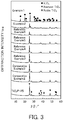
- Fig. 3 illustrates powder XRD patterns of Example 1 (V 2 O 5 _SG_300) and Example 2, Reference Examples 3 to 6, and Comparative Examples 2 and 3 (xwt% V 2 O 5 /TiO 2 ).
- Example 1 In the powder XRD patterns of Example 1 (V 2 O 5 _SG_300), Reference Example 1 (V 2 O 5 _300), Reference Example 2 (V 2 O 5 _400), and Comparative Example 1 (V 2 O 5 _500), only peaks for V 2 O 5 were observed regardless of the thermal decomposition temperature and the production method.
- Example 2 In the powder XRD patterns of Example 2, Reference Examples 3 to 6, and Comparative Examples 2 and 3 (xwt% V 2 O 5 /TiO 2 ), peaks for V 2 O 5 were not observed at 9 wt% or less and thus V 2 O 5 is believed to be highly dispersed in TiO 2 .
- V 2 O 5 supported When the amount of V 2 O 5 supported was increased to 20 wt%, peaks for V 2 O 5 were observed at 22.2° and 27.4°, and the V 2 O 5 peak intensity increased as the amount of V 2 O 5 supported was increased. On the other hand, the TiO 2 peak intensity tended to decrease.
- the BET specific surface area was measured with a MicrotracBEL BELSORP-max. Pretreatment was performed in an Ar atmosphere at 200°C for 2 hours, and then measurement was performed at 196°C.
- Table 1 shows BET specific surface areas of Reference Example 1 (V 2 O 5 _300), Reference Example 2 (V 2 O 5 _400), Comparative Example 1 (V 2 O 5 _500), Example 1 (V 2 O 5 _SG_300), Comparative Examples 2 and 3, Reference Examples 3 to 6, and Examples 2 and 3 (xwt% V 2 O 5 /TiO 2 catalyst), and Comparative Example 4 (existing catalyst).
- the BET specific surface area decreased with increasing the thermal decomposition temperature.
- the vanadium pentoxide in Reference Example 1 (V 2 O 5 _300) in which the thermal decomposition was performed at 300°C had a maximum BET specific surface area of 16.6 m 2 g -1 .
- the vanadium pentoxide obtained at 300°C through a sol-gel process had a larger BET specific surface area of 62.9 m 2 g -1 .
- Reference Examples 3 to 6, Examples 2 and 3, and Comparative Examples 2 and 3 as the amount of vanadium pentoxide supported was increased, pores in TiO 2 were filled and the BET specific surface area decreased.
- NO in represents a NO concentration at an inlet of a reaction tube
- NO out represents a NO concentration at an outlet of the reaction tube
- N 2out represents a N 2 concentration at the outlet of the reaction tube
- NH 3in represents an NH 3 concentration at the inlet of the reaction tube
- NH 3out represents an NH 3 concentration at the outlet of the reaction tube.
- Fig. 4 illustrates the NH 3 -SCR activity of the vanadium pentoxide catalysts.
- the NO conversion ratio increased as the thermal decomposition temperature was decreased.
- the highest activity was exhibited in Reference Example 1 (V 2 O 5 _300°C) in which the catalyst was obtained at a thermal decomposition temperature of 300°C.
- a NO conversion ratio of 80% or more was achieved when any of the catalysts in Reference Example 1 (V 2 O 5 _300°C), Reference Example 2 (V 2 O 5 _400°C), and Example 1 (V 2 O 5 _SG_300°C) was used.
- the NO conversion ratio was higher in any of Examples than in Comparative Example 1 and Comparative Example 4.
- the specific surface area of the vanadium pentoxide increases as the thermal decomposition temperature is decreased. Therefore, it is believed that the low-temperature NH 3 -SCR activity that uses a bulk vanadium pentoxide catalyst is attributable to the BET specific surface area.
- the vanadium pentoxide was produced through a sol-gel process that uses oxalic acid in order to increase the BET specific surface area in Example 1.
- the BET specific surface area of the vanadium pentoxide produced through this process is 62.9 m 2 g -1 as shown in Table 1, which is about four times larger than the BET specific surface areas of the vanadium pentoxides produced through a thermal decomposition process.
- the NO conversion ratio in Example 1 (V 2 O 5 _SG_300°C) was increased by 80% to 200% at 100°C to 150°C compared with the vanadium pentoxides produced through a thermal decomposition process.
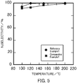
- Fig. 5 illustrates, as examples, the N 2 selectivities in Reference Example 1 (V 2 O 5 _300°C) and Comparative Example 1 (V 2 O 5 _500°C).
- Fig. 6 illustrates the measurement results.
- Fig. 6(a) illustrates the NO conversion ratio at a reaction temperature of 120°C.
- Fig. 6(b) illustrates the NO conversion ratio at a reaction temperature of 100°C.
- the 80% NO detoxification was about 15 Lh -1 g cat -1 at 120°C and about 11 Lh -1 g cat -1 at 100°C.
- the N 2 selectivity was almost 100%.
- Fig. 8 illustrates the experimental results. No change occurred to the catalytic activity of NO. After the completion of the temperature increase to 150°C, the SO 2 concentration did not decrease though H 2 O and O 2 were constantly present. Consequently, SO 2 did not react. Accordingly, the denitration catalysts in Examples were found to have S resistance.
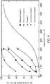
- Fig. 9 illustrates the relationship between the amount of vanadium pentoxide supported and the NO conversion ratio at each reaction temperature.
- Fig. 9(a) illustrates the relationship between the amount of vanadium pentoxide supported and the NO conversion ratio at a reaction temperature of 120°C.
- Fig. 9(b) illustrates the relationship between the amount of vanadium pentoxide supported and the NO conversion ratio at a reaction temperature of 150°C
- Fig. 9(c) illustrates the relationship at a reaction temperature of 100°C.
- the catalyst in which the amount of vanadium pentoxide supported is 100 wt% is the denitration catalyst V 2 O 5 _SG_300 produced in Example 1.
- the points plotted using a square indicate a NO conversion ratio of the existing catalyst in Comparative Example 4. All the graphs showed that, on the whole, the NO conversion ratio increased as the amount of vanadium pentoxide supported was increased. Herein, all the graphs showed that the catalyst in which the amount of vanadium pentoxide supported was 3.3 wt% had a higher NO conversion ratio than the catalyst in which the amount of vanadium pentoxide supported was 9.0 wt%. Specifically, as illustrated in Fig. 9(a) , in the NH 3 -SCR reaction at a reaction temperature of 120°C, the NO conversion ratio reached 80% when the amount of vanadium pentoxide supported was increased to 80 wt%. As illustrated in Fig.
- Fig. 10(a) illustrates the relationship between the BET specific surface area and the NO conversion ratio of the denitration catalysts in which vanadium pentoxide was supported on titanium oxide.
- the BET specific surface area decreased, but the activity increased on the whole.
- Fig. 10(b) illustrates the relationship between the BET specific surface area and the NO conversion ratio of both the denitration catalysts in which vanadium pentoxide was supported on titanium oxide and the denitration catalysts in which vanadium pentoxide was not supported on titanium oxide. In the catalysts in which vanadium pentoxide was not supported on titanium oxide, the activity increased with increasing the BET specific surface area.
- Example 1 of the above-described "1.1 Examples and Comparative Examples”, ammonium vanadate was dissolved in an oxalic acid solution such that the molar ratio of vanadium and oxalic acid was 1:3, then water was evaporated, drying was performed, and the resulting dried powder was fired. Thus, a denitration catalyst was produced.
- the denitration catalysts of Reference Example 7, Examples 4 to 6, and Reference Example 8 the molar ratios of vanadium and oxalic acid were set to 1:1, 1:2, 1:3, 1:4, and 1:5, respectively.
- V 2 O 5 _SG_300 in “Example 1" of “1.1 Examples and Comparative Examples” and “V 2 O 5 _SG_1:3” in Example 5 were substantially the same, but the sample name “V 2 O 5 _SG_1:3” in “Example 5" was used for the sake of convenience of description.
- a surfactant may be added to the oxalic acid solution.
- surfactant examples include anionic surfactants such as hexadecyltrimethylammonium bromide (CTAB), sodium lauryl sulfate (SDS), and hexadecylamine; cationic surfactants; amphoteric surfactants; and nonionic surfactants.
- anionic surfactants such as hexadecyltrimethylammonium bromide (CTAB), sodium lauryl sulfate (SDS), and hexadecylamine
- cationic surfactants such as hexadecyltrimethylammonium bromide (CTAB), sodium lauryl sulfate (SDS), and hexadecylamine
- cationic surfactants such as hexadecyltrimethylammonium bromide (CTAB), sodium lauryl sulfate (SDS), and hexadecylamine
- cationic surfactants such as hexadecy
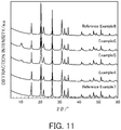
- Fig. 11 illustrates powder XRD patterns of Reference Example 7, Examples 4 to 6, and Reference Example 8 (V 2 O 5 _SG).
- vanadium pentoxides Reference Examples 7, 7, and 10
- Examples 5 and 6 produced using the solutions having vanadium:oxalic acid ratios of 1:3 and 1:5
- an unidentified peak was detected at 11° in addition to the peaks for orthorhombic V 2 O 5 .
- the peak has not been identified yet.
- the BET specific surface area was measured with a MicrotracBEL BELSORP-max. Pretreatment was performed in an Ar atmosphere at 200°C for 2 hours, and then measurement was performed at 196°C.
- Table 5 shows BET specific surface areas of Reference Example 7 (V 2 O 5 _SG_1:1), Example 4 (V 2 O 5 _SG_1:2), Example 5 (V 2 O 5 _SG_1:3), Example 6 (V 2 O 5 _SG_1:4), and Reference Example 8 (V 2 O 5 _SG_1:5).
- Fig. 12 illustrates the NH 3 -SCR activity of each V 2 O 5 _SG catalyst.
- Fig. 12(a) illustrates the NO conversion ratio plotted against reaction temperature in the NH 3 -SCR reaction that uses each catalyst.
- Fig. 12(b) illustrates the relationship between the vanadium:oxalic acid ratio and the NO conversion ratio at a reaction temperature of 120°C.
- the catalyst of Example 5 V 2 O 5 _SG_1:3 having a vanadium:oxalic acid ratio of 1:3, the highest NO conversion ratio was achieved.
- the NO conversion ratio decreased.
- the NO conversion ratio in Example 6 (V 2 O 5 _SG_1:4) was lower than that in Example 4 (V 2 O 5 _SG_1:2) despite the fact that the specific surface area in Example 6 was larger than that in Example 4.
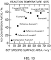
- Fig. 13 illustrates the relationship between the BET specific surface area and the NO conversion ratio in Examples 4 to 6 and Reference Example 7 (V 2 O 5 _SG), Reference Example 1 (V 2 O 5 _300), Reference Example 2 (V 2 O 5 _400), and Comparative Example 1 (V 2 O 5 _500).
- the point plotted using a square indicates the relationship between the BET specific surface area and the NO conversion ratio after the selective catalytic reduction reaction in Example 5 (V 2 O 5 _SG_1:3).
- the highest NO conversion ratio was achieved in the catalyst of Example 5 (V 2 O 5 _SG_1:3) having a vanadium:oxalic acid ratio of 1:3.
- the amount of acid sites on the surface of the catalyst can be estimated by NH 3 -TPD (TPD: temperature programed desorption).
- TPD temperature programed desorption
- 0.1 g of each of the catalysts in Reference Example 1 (V 2 O 5 _300), Reference Example 2 (V 2 O 5 _400), Comparative Example 1 (V 2 O 5 _500), Example 4 (V 2 O 5 _SG_1:2), and Example 5 (V 2 O 5 _SG_1:3) was pretreated at 300°C for 1 hour while He (50 ml/min) was caused to flow.
- the temperature was decreased to 100°C, and 5% ammonia/He (50 ml/min) was caused to flow for 30 minutes to adsorb ammonia.
- the flow gas was changed to He (50 ml/min) and this state was kept for 30 minutes for stabilization.
- the temperature was increased at 10 °C/min and ammonia, which has a mass number of 16, was monitored with a mass spectrometer.
- Table 6 shows the measurement results of the amount of NH 3 desorbed when the catalysts in Reference Example 1 (V 2 O 5 _300), Reference Example 2 (V 2 O 5 _400), Comparative Example 1 (V 2 O 5 _500), Example 4 (V 2 O 5 _SG_1:2), and Example 5 (V 2 O 5 _SG_1:3) were used.
- Fig. 14 is a graph obtained by plotting the amount of NH 3 desorbed as a function of the BET specific surface area of each catalyst. The graph in Fig. 14 showed that the amount of NH 3 desorbed increased substantially in proportion to the BET specific surface area of V 2 O 5 .
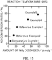
- Fig. 15 is a graph obtained by plotting the NO conversion ratio as a function of the amount of NH 3 desorbed in each catalyst. The graph showed that the NO conversion ratio increased as the catalyst had a larger amount of NH 3 desorbed, that is, a larger amount of acid sites on the surface of the catalyst.
- the denitration catalyst of the present invention that contains 3.3 wt% or more of vanadium oxide in terms of vanadium pentoxide and has a specific surface area of 10 m 2 /g or more exhibits a high denitration efficiency at a low temperature of 200°C or lower in the selective catalytic reduction reaction that uses ammonia as a reducing agent. On the other hand, oxidation of SO 2 is not found.
Landscapes
- Chemical & Material Sciences (AREA)
- Engineering & Computer Science (AREA)
- Chemical Kinetics & Catalysis (AREA)
- Materials Engineering (AREA)
- Organic Chemistry (AREA)
- Combustion & Propulsion (AREA)
- General Engineering & Computer Science (AREA)
- Mechanical Engineering (AREA)
- Health & Medical Sciences (AREA)
- Environmental & Geological Engineering (AREA)
- Toxicology (AREA)
- Oil, Petroleum & Natural Gas (AREA)
- General Chemical & Material Sciences (AREA)
- Analytical Chemistry (AREA)
- Biomedical Technology (AREA)
- Thermal Sciences (AREA)
- Physics & Mathematics (AREA)
- Dispersion Chemistry (AREA)
- Life Sciences & Earth Sciences (AREA)
- Sustainable Development (AREA)
- Catalysts (AREA)
- Exhaust Gas Treatment By Means Of Catalyst (AREA)
- Chimneys And Flues (AREA)
- Exhaust Gas After Treatment (AREA)
- Incineration Of Waste (AREA)
Abstract
Description
- The present invention relates to a combustion system. More specifically, the present invention relates to a combustion system including a combustion device, an exhaust line through which exhaust gas flows, an air preheater that recovers heat from the exhaust gas, and a denitration device that removes nitrogen oxide from the exhaust gas.
- In existing combustion systems including a boiler, thermal energy is generated as a result of combustion of fuel such as coal in the boiler, and then, for example, the thermal energy is converted into electric energy. The combustion of fuel in the boiler generates an exhaust gas containing nitrogen oxide.
- The exhaust gas generated in the boiler is discharged to the outside from the boiler through an exhaust line. In consideration of environmental factors, nitrogen oxide is removed, by a denitration device, from the exhaust gas that is discharged to the outside from the boiler.
- In general, a denitration catalyst such as a vanadium/titanium catalyst (V2O5/TiO2) is used for denitration devices that remove nitrogen oxide from exhaust gas. The vanadium/titanium catalyst exhibits high catalytic activity in a high-temperature (e.g., about 370°C) environment. Therefore, such a denitration device is disposed in an area near the outlet of exhaust gas in a boiler or on the upstream side of an exhaust line in, for example, a thermal power plant (e.g., refer to Patent Document 1).
- Patent Document 1: Japanese Unexamined Patent Application, Publication No.
2011-190940 - However, such an area near the outlet of exhaust gas in a boiler or on the upstream side of an exhaust line is in a high-temperature environment as described above and furthermore coal ash and S components are present in a high concentration, which readily deteriorates the denitration catalyst. If the denitration catalyst rapidly deteriorates, the denitration catalyst needs to be frequently replaced and thus the operation cost of the combustion system tends to increase.
- In the case where nitrogen oxide is removed from exhaust gas by a selective catalytic reduction method in the denitration device, if the denitration catalyst deteriorates, ammonia used as a reducing agent leaks from the denitration device. If ammonia leaks from the denitration device, the ammonia and S components in the exhaust gas react with each other to generate ammonium sulfate. The ammonium sulfate adheres to an air preheater disposed downstream from the denitration device. When ammonium sulfate adheres to and deposits on the air preheater, for example, the air preheater needs to be cleaned to prevent clogging of a flow path of exhaust gas, which further increases the operation cost of the combustion system.
- In view of the foregoing, it is an object of the present invention to provide a combustion system operated at low cost. Means for Solving the Problems
- The present invention relates to a combustion system including a combustion device that burns fuel, an exhaust line through which exhaust gas flows, the exhaust gas being generated through combustion of the fuel in the combustion device, an air preheater that is disposed in the exhaust line and that recovers heat from the exhaust gas, and a denitration device that is disposed in the exhaust line and that removes nitrogen oxide from the exhaust gas using a denitration catalyst, wherein the denitration device is disposed downstream from the air preheater in the exhaust line, and the denitration catalyst contains 43 wt% or more of vanadium pentoxide and has a BET specific surface area of 30 m2/g or more.
- In the denitration catalyst, an amount of NH3 desorbed by NH3-TPD (TPD: temperature programed desorption) is preferably 10.0 µmol/g or more.
- The denitration device preferably removes nitrogen oxide from the exhaust gas by a selective catalytic reduction method.
- The fuel is preferably natural gas.
- Since the denitration device is disposed downstream from the air preheater, the denitration catalyst used in the denitration device does not readily deteriorate. Therefore, a thermal power generation system operated at low cost can be provided.
-
-
Fig. 1 illustrates a configuration of a thermal power generation system according to an embodiment of the present invention. -
Fig. 2 illustrates the powder X-ray diffraction results of vanadium pentoxide catalysts produced in Example 1, Reference Examples 1 and 2, and Comparative Example 1. -
Fig. 3 illustrates the powder X-ray diffraction results of vanadium pentoxide catalysts produced in Examples 1 and 2, Reference Examples 3 to 6, and Comparative Examples 2 and 3. -
Fig. 4 illustrates the NH3-SCR activity of vanadium pentoxide catalysts produced in Example 1, Reference Examples 1 and 2, and Comparative Examples 1 and 4. -
Fig. 5 illustrates the relationship between the reaction temperature and the N2 selectivity in a selective catalytic reduction reaction that uses vanadium pentoxide catalysts produced in Reference Example 1 and Comparative Example 1. -
Fig. 6 illustrates the space velocity dependency in the case where a vanadium pentoxide catalyst produced in Reference Example 1 is used in an NH3-SCR reaction. -
Fig. 7 illustrates a change in the NO conversion ratio over time in the case where a vanadium pentoxide catalyst produced in Reference Example 1 is used in a selective catalytic reduction reaction in coexistence with water. -
Fig. 8 illustrates changes in the NH3, NO, and SO2 concentrations over time in the case where a vanadium pentoxide catalyst produced in Reference Example 1 is used in a selective catalytic reduction reaction in coexistence with S. -
Fig. 9 illustrates the relationship between the amount of vanadium pentoxide supported and the NO conversion ratio of a vanadium pentoxide catalyst produced in each of Examples at each reaction temperature. -
Fig. 10 illustrates the relationship between the BET specific surface area and the NO conversion ratio of a vanadium pentoxide catalyst produced in each of Examples, Reference Examples, and Comparative Examples. -
Fig. 11 illustrates the powder X-ray diffraction results of vanadium pentoxide catalysts produced in Examples 4 to 6 and Reference Examples 7 and 8. -
Fig. 12 illustrates the NH3-SCR activity of vanadium pentoxide catalysts produced in Examples 4 to 6 and Reference Examples 7 and 8. -
Fig. 13 illustrates the relationship between the specific surface area and the NO conversion ratio of vanadium pentoxide catalysts produced in Examples 4 to 6, Reference Examples 1, 2, and 7, and Comparative Example 1. -
Fig. 14 illustrates the relationship between the BET specific surface area and the amount of NH3 desorbed of vanadium pentoxide catalysts produced in Examples 4 and 5, Reference Examples 1 and 2, and Comparative Example 1. -
Fig. 15 illustrates the relationship between the amount of NH3 desorbed and the NO conversion ratio of vanadium pentoxide catalysts produced in Examples 4 and 5, Reference Examples 1 and 2, and Comparative Example 1. - Hereafter, an embodiment of the present invention will be described with reference to the attached drawings.
Fig. 1 illustrates a configuration of a thermalpower generation system 1 according to this embodiment. As illustrated inFig. 1 , the thermalpower generation system 1 includes aboiler 10 serving as a combustion device, avaporizer 20, an exhaust line L1, anair preheater 30, adenitration device 40, an induceddraft fan 50, and asmokestack 60. - The
boiler 10 burns natural gas serving as fuel together with air. In theboiler 10, combustion of natural gas generates exhaust gas. Note that the combustion of natural gas does not generate combustion ash unlike the combustion of pulverized coal. Therefore, the thermalpower generation system 1 does not necessarily include a dust collector. Furthermore, since natural gas does not contain a S component, the thermalpower generation system 1 also does not necessarily include a desulfurization device. - The
boiler 10 has a substantially inverted U shape on the whole. The exhaust gas generated in theboiler 10 moves along the shape of theboiler 10 so as to draw an inverted U shape. The temperature of exhaust gas near the outlet of theboiler 10 is, for example, 300°C to 400°C. - The
vaporizer 20 vaporizes natural gas supplied from an LNG tank (not illustrated) and supplies the natural gas to theboiler 10. The natural gas may be vaporized by using a vaporizer that uses seawater (open rack vaporizer), a vaporizer in which natural gas is heated using hot water heated with a gas burner (submerged combustion vaporizer), or a vaporizer that performs several step heat exchanges using intermediate fluid. - The
boiler 10 is connected to an upstream portion of the exhaust line L1. The exhaust line L1 is a flow pass through which the exhaust gas generated in theboiler 10 flows. - The
air preheater 30 is disposed in the exhaust line L1. Theair preheater 30 recovers heat from the exhaust gas by performing heat exchange between the exhaust gas and air for combustion that is sent from a forced draft fan (not illustrated). The air for combustion is heated in theair preheater 30 and then supplied to theboiler 10. - The
denitration device 40 is disposed downstream from theair preheater 30 in the exhaust line L1. The exhaust gas that has been cooled in theair preheater 30 is supplied to thedenitration device 40. Thedenitration device 40 removes nitrogen oxide from the exhaust gas using a denitration catalyst. The denitration catalyst used in thedenitration device 40 will be specifically described later. The temperature of the exhaust gas in thedenitration device 40 is, for example, 130°C to 200°C. - In the
denitration device 40, nitrogen oxide is removed from the exhaust gas by a selective catalytic reduction method. In the selective catalytic reduction method, nitrogen and water are generated from nitrogen oxide by using a reducing agent and a denitration catalyst. Thus, nitrogen oxide can be efficiently removed from the exhaust gas. The reducing agent used in the selective catalytic reduction method contains at least one of ammonia and urea. When ammonia is used as a reducing agent, ammonia in any state, such as ammonia gas, liquid ammonia, or an aqueous ammonia solution, may be used. - More specifically, the
denitration device 40 may have the following mechanism. Ammonia gas is injected to the introduced exhaust gas and then the mixed gas is brought into contact with the denitration catalyst. - The induced
draft fan 50 is disposed downstream from thedenitration device 40 in the exhaust line L1. In the induceddraft fan 60, the exhaust gas from which nitrogen oxide has been removed in thedenitration device 40 is taken in from the upstream side and sent out to the downstream side. - The
smokestack 60 is connected to a downstream portion of the exhaust line L1. The exhaust gas from which nitrogen oxide has been removed in thedenitration device 40 is introduced into thesmokestack 60. The temperature of the exhaust gas in thedenitration device 40 is, for example, 130°C to 200°C. Therefore, the exhaust gas introduced into thesmokestack 60 is effectively discharged from the upper part of thesmokestack 100 because of a stack effect. The temperature of the exhaust gas near the outlet of thesmokestack 100 is, for example, 110°C. - Next, the denitration catalyst used in the
denitration device 40 will be described. The denitration catalyst of the present invention contains 43 wt% or more of vanadium pentoxide and has a BET specific surface area of 30 m2/g or more. Such a denitration catalyst can exhibit a high denitration effect even in a low-temperature environment compared with known denitration catalysts such as a vanadium/titanium catalyst. - Specifically, when a denitration catalyst containing 3.3 wt% or more of vanadium oxide in terms of vanadium pentoxide is used in a selective catalytic reduction reaction (NH3-SCR) that uses ammonia as a reducing agent, the NO conversion ratio is approximately 35% or more at a reaction temperature of 120°C and approximately 60% or more at a reaction temperature of 150°C. Even at a reaction temperature of 100°C, the NO conversion ratio exceeds 20%. In contrast, if the denitration catalyst contains only less than 3.3 wt% of vanadium oxide in terms of vanadium pentoxide, the NO conversion ratio is less than 20% at a reaction temperature of 120°C and even at a reaction temperature of 150°C.
- As described above, the denitration catalyst according to the present invention contains 43 wt% or more of vanadium oxide in terms of vanadium pentoxide, and may also contain titanium oxide as another component in addition to the vanadium oxide. Furthermore, a noble metal, a base metal, and a main group metal may be contained. Preferably, for example, tungsten oxide, chromium oxide, and molybdenum oxide can also be contained.
- It has been described that the denitration catalyst preferably contains 43 wt% or more of vanadium oxide in terms of vanadium pentoxide. Preferably, the denitration catalyst may contain 80 wt% or more of vanadium oxide in terms of vanadium pentoxide. More preferably, the content of vanadium oxide in the denitration catalyst may be 100%.
- The above-described vanadium oxide includes vanadium(II) oxide (VO), vanadium(III) trioxide (V2O3), vanadium(IV) dioxide (V2O4), and vanadium(V) pentoxide (V2O5), and the V element in vanadium pentoxide (V2O5) may have a pentavalent, tetravalent, trivalent, or divalent form in the denitration reaction.
- Regarding the BET specific surface area of the denitration catalyst, for example, in the NH3-SCR that is performed at a reaction temperature of 120°C using a denitration catalyst containing vanadium pentoxide and having a BET specific surface area of 13.5 m2/g, the NO conversion ratio exceeds 20%. Even in the NH3-SCR that is performed at a reaction temperature of 120°C using a denitration catalyst containing vanadium pentoxide and having a BET specific surface area of 16.6 m2/g, the NO conversion ratio exceeds 20%. In contrast, in the NH3-SCR that is performed at a reaction temperature of 120°C using, for example, a denitration catalyst having a BET specific surface area of 4.68 m2/g, which is a denitration catalyst having a BET specific surface area of less than 10 m2/g, the NO conversion ratio falls below 20%.
- The BET specific surface area of the denitration catalyst is 30 m2/g or more and may be preferably 40 m2/g or more. More preferably, the BET specific surface area of the denitration catalyst may be 50 m2/g or more. More preferably, the BET specific surface area of the denitration catalyst may be 60 m2/g or more.
- The BET specific surface area of the denitration catalyst is preferably measured in conformity with the conditions specified in JIS Z 8830:2013. Specifically, the BET specific surface area can be measured by a method described in Examples below.
- The denitration catalyst of the present invention is used for denitration at 200°C or lower. Preferably, the denitration catalyst is used for denitration at 160°C or higher and 200°C or lower. Thus, oxidation of SO2 into SO3 does not occur during the NH3-SCR reaction.
- Regarding the amount of NH3 desorbed by NH3-TPD (TPD: temperature programed desorption), when the amount of NH3 desorbed exceeds 10.0 µmol/g, the NO conversion ratio of the denitration catalyst in the NH3-SCR at a reaction temperature of 120°C is 20% or more. In contrast, when the amount of NH3 desorbed falls below 10.0 µmol/g, the NO conversion ratio of the denitration catalyst in the NH3-SCR at a reaction temperature of 120°C falls below 20%.
- In the denitration catalyst of the present invention, the amount of NH3 desorbed by NH3-TPD (TPD: temperature programed desorption) is 10.0 µmol/g or more. Preferably, the amount of NH3 desorbed by NH3-TPD may be 20.0 µmol/g or more. More preferably, the amount of NH3 desorbed by NH3-TPD may be 50.0 µmol/g or more. More preferably, the amount of NH3 desorbed by NH3-TPD may be 70.0 µmol/g or more.
- The denitration catalyst containing 3.3 wt% or more of vanadium oxide in terms of vanadium pentoxide and having a BET specific surface area of 10 m2/g or more can be produced by any of a thermal decomposition process, a sol-gel process, and an impregnation process. Hereafter, a method for producing the denitration catalyst containing 3.3 wt% or more of vanadium pentoxide and having a specific surface area of 10 m2/g or more by a thermal decomposition process, a sol-gel process, or an impregnation process will be described.
- The thermal decomposition process includes a step of thermally decomposing a vanadate. Examples of the vanadate that may be used include ammonium vanadate, magnesium vanadate, strontium vanadate, barium vanadate, zinc vanadate, tin vanadate, and lithium vanadate.
- In the thermal decomposition process, the vanadate is preferably thermally decomposed at 300°C to 400°C.
- The sol-gel process includes a step of dissolving a vanadate in a chelate compound, performing drying, and performing firing. Examples of the chelate compound that may be used include compounds having a plurality of carboxy groups, such as oxalic acid and citric acid; compounds having a plurality of amino groups, such as acetylacetonate and ethylenediamine; and compounds having a plurality of hydroxy groups, such as ethylene glycol.
- The sol-gel process preferably includes a step of dissolving a vanadate in a chelate compound such that the molar ratio of vanadium and the chelate compound is, for example, 1:1 to 1:5, though this is dependent on the chelate compound. Preferably, the molar ratio of the vanadate and the chelate compound may be 1:2 to 1:4.
- The impregnation process includes a step of dissolving a vanadate in a chelate compound, adding a carrier, performing drying, and then performing firing. Examples of the carrier that may be used include titanium oxide, aluminum oxide, and silica. As above, examples of the chelate compound that may be used include compounds having a plurality of carboxy groups, such as oxalic acid and citric acid; compounds having a plurality of amino groups, such as acetylacetonate and ethylenediamine; and compounds having a plurality of hydroxy groups, such as ethylene glycol.
- In the impregnation process, xwt% V2O5/TiO2 (x ≥ 43) may be produced as a denitration catalyst according to an embodiment of the present invention by, for example, dissolving ammonium vanadate in an oxalic acid solution, adding titanium oxide (TiO2) serving as a carrier, performing drying, and then performing firing.
- The thus-produced denitration catalyst normally contains 3.3 wt% or more of vanadium pentoxide and has a specific surface area of 10 m2/g or more.
- The
combustion system 1 according to the above embodiment produces the following effects. - (1) In the
combustion system 1 according to the above embodiment, thedenitration device 40 is disposed downstream from theair preheater 30 in the exhaust line L1 through which the exhaust gas generated in the boiler (combustion device) 10 flows. Furthermore, in the above embodiment, the denitration catalyst containing 43 wt% or more of vanadium pentoxide and having a BET specific surface area of 30 m2/g or more is used in thedenitration device 40. Since the denitration catalyst in the above embodiment can be used for denitration at 200°C or lower, thedenitration device 40 can be disposed downstream from theair preheater 30. This decreases the temperature of exhaust gas subjected to denitration with the denitration catalyst, which can suppress the deterioration of the denitration catalyst. In thecombustion system 1 according to the above embodiment, a dust collector and a desulfurization device are not essential components. Therefore, the configuration of thecombustion system 1 is simplified, which can reduce the installation cost. - (2) As described above, in the denitration catalyst used in the
denitration device 40, the amount of NH3 desorbed by NH3-TPD (TPD: temperature programed desorption) is preferably 10.0 µmol/g or more. When this denitration catalyst is used in the NH3-SCR at a reaction temperature of 120°C, the NO conversion ratio exceeds 20%. - (3) In the above embodiment, the
denitration device 40 removes nitrogen oxide from the exhaust gas by a selective catalytic reduction method. In the case where nitrogen oxide is removed from the exhaust gas by a selective catalytic reduction method in thedenitration device 40, if the denitration catalyst deteriorates, ammonia (or urea) used as a reducing agent leaks from thedenitration device 40. As described above, thedenitration device 40 is not disposed upstream from theair preheater 30 that is normally disposed near theboiler 10 in the exhaust line L1. This does not cause clogging of theair preheater 30 due to ammonium sulfate generated as a result of reaction between ammonia and a S component in the exhaust gas. Since the clogging of theair preheater 30 is prevented in such a manner, the cost for cleaning theair preheater 30 can be reduced. - (4) In the
combustion system 1 according to the above embodiment, the fuel burned in the boiler (combustion device) 10 is natural gas. When natural gas is burned in a boiler of a thermal power generation system, ammonium sulfate is not generated because the natural gas does not contain S component. Consequently, the clogging of theair preheater 30 is prevented and also there is no need to include a desulfurization device in thecombustion system 1. Furthermore, since dust is not generated during combustion of natural gas, there is also no need to include a dust collector in thecombustion system 1. Therefore, the configuration of thecombustion system 1 is simplified, which can reduce the installation cost. - The present invention is not limited to the above embodiment, and any of modifications, improvements, and the like are included in the present invention as long as the object of the present invention is achieved.
- It has been described in the above embodiment that the
denitration device 40 removes nitrogen oxide from the exhaust gas by a selective catalytic reduction method. However, the present invention is not limited thereto. For example, in the present invention, thedenitration device 40 may remove nitrogen oxide from the exhaust gas by a non-selective catalytic reduction method. - It has been described in the above embodiment that the
denitration device 40 is disposed immediately after theair preheater 30. However, the present invention is not limited thereto. The denitration device 90 may be disposed at any position downstream from theair preheater 30. After the exhaust gas is reheated using a gas-gas heater, denitration may be performed using the denitration device 90. - In the above embodiment, the LNG thermal power generation system has been described as an example of the
combustion system 1. However, the present invention is not limited thereto. For example, the present invention is applicable to an integrated gasification combined cycle. - Hereafter, Examples of the catalyst component of the present invention will be specifically described together with Reference Examples and Comparative Examples. The present invention is not limited by Examples.
- Ammonium vanadate (NH4VO3) was thermally decomposed in the air at 300°C for 4 hours to obtain vanadium pentoxide (V2O5). The obtained vanadium pentoxide was used as a denitration catalyst in Reference Example 1. The sample name of the denitration catalyst in Reference Example 1 was "V2O5_300".
- Ammonium vanadate was thermally decomposed in the air at 400°C for 4 hours to obtain vanadium pentoxide. The obtained vanadium pentoxide was used as a denitration catalyst in Reference Example 2. The sample name of the denitration catalyst in Reference Example 2 was "V2O5_400".
- Ammonium vanadate was thermally decomposed in the air at 500°C for 4 hours to obtain vanadium pentoxide. The obtained vanadium pentoxide was used as a denitration catalyst in Comparative Example 1. The sample name of the denitration catalyst in Comparative Example 1 was "V2O5_500".
- Ammonium vanadate was dissolved in an oxalic acid solution (molar ratio of vanadium:oxalic acid = 1:3). After ammonium vanadate was completely dissolved, water in the solution was evaporated on a hot stirrer, and drying was performed in a dryer at 120°C for one night. Then, the dried powder was fired in the air at 300°C for 4 hours. The vanadium pentoxide after firing was used as a denitration catalyst in Example 1. The sample name of the denitration catalyst in Example 1 obtained by this sol-gel process was "V2O5_SG_300". Denitration catalysts obtained at different molar ratios of vanadium and oxalic acid when ammonium vanadate is dissolved in an oxalic acid solution will be described later.
- Ammonium vanadate was added to an oxalic acid solution and stirred for 10 minutes, and titanium oxide serving as a carrier was gradually added. Then, water in the solution was evaporated on a hot stirrer and drying was performed in a dryer at 120°C for one night. Subsequently, the dried powder was fired in the air at 300°C for 4 hours. As a result, the denitration catalyst after firing that contained 0.3 wt% of vanadium pentoxide was used as a denitration catalyst in Comparative Example 2. The sample name of the denitration catalyst in Comparative Example 2 was "0.3wt% V2O5/TiO2".
- The denitration catalyst after firing that was obtained by the same method as in Comparative Example 2 and contained 0.9 wt% of vanadium pentoxide was used as a denitration catalyst in Comparative Example 3. The sample name of the denitration catalyst in Comparative Example 3 was "0.9wt% V2O5/TiO2".
- The denitration catalyst after firing that was obtained by the same method as in Comparative Example 2 and contained 3.3 wt% of vanadium pentoxide was used as a denitration catalyst in Reference Example 3. The sample name of the denitration catalyst in Reference Example 3 was "3.3wt% V2O5/TiO2".
- The denitration catalyst after firing that was obtained by the same method as in Comparative Example 2 and contained 9 wt% of vanadium pentoxide was used as a denitration catalyst in Reference Example 4. The sample name of the denitration catalyst in Reference Example 4 was "9wt% V2O5/TiO2".
- The denitration catalyst after firing that was obtained by the same method as in Comparative Example 2 and contained 20 wt% of vanadium pentoxide was used as a denitration catalyst in Reference Example 5. The sample name of the denitration catalyst in Reference Example 5 was "20wt% V2O5/TiO2".
- The denitration catalyst after firing that was obtained by the same method as in Comparative Example 2 and contained 33 wt% of vanadium pentoxide was used as a denitration catalyst in Reference Example 6. The sample name of the denitration catalyst in Reference Example 6 was "33wt% V2O5/TiO2".
- The denitration catalyst after firing that was obtained by the same method as in Comparative Example 2 and contained 43 wt% of vanadium pentoxide was used as a denitration catalyst in Example 2. The sample name of the denitration catalyst in Example 2 was "43wt% V2O5/TiO2".
- The denitration catalyst after firing that was obtained by the same method as in Comparative Example 2 and contained 80 wt% of vanadium pentoxide was used as a denitration catalyst in Example 3. The sample name of the denitration catalyst in Example 3 was "80wt% V2O5/TiO2".
- An existing catalyst was used in Comparative Example 4. The existing catalyst is a catalyst in which, for example, tungsten oxide (WO3) (content: 10.72 wt%) and silica (SiO2)
(content: 6.25 wt%) are supported on titanium oxide (TiO2)
(content: 79.67 wt%) and which contains about 0.5% of vanadium. - Powder X-ray diffraction analysis was performed with a Rigaku smart lab using Cu-Ka.
-
Fig. 2 illustrates powder XRD patterns of Example 1 (V2O5_SG_300), Reference Example 1 (V2O5_300), Reference Example 2 (V2O5_400), and Comparative Example 1 (V2O5_500).Fig. 3 illustrates powder XRD patterns of Example 1 (V2O5_SG_300) and Example 2, Reference Examples 3 to 6, and Comparative Examples 2 and 3 (xwt% V2O5/TiO2). In the powder XRD patterns of Example 1 (V2O5_SG_300), Reference Example 1 (V2O5_300), Reference Example 2 (V2O5_400), and Comparative Example 1 (V2O5_500), only peaks for V2O5 were observed regardless of the thermal decomposition temperature and the production method. In the powder XRD patterns of Example 2, Reference Examples 3 to 6, and Comparative Examples 2 and 3 (xwt% V2O5/TiO2), peaks for V2O5 were not observed at 9 wt% or less and thus V2O5 is believed to be highly dispersed in TiO2. When the amount of V2O5 supported was increased to 20 wt%, peaks for V2O5 were observed at 22.2° and 27.4°, and the V2O5 peak intensity increased as the amount of V2O5 supported was increased. On the other hand, the TiO2 peak intensity tended to decrease. - The BET specific surface area was measured with a MicrotracBEL BELSORP-max. Pretreatment was performed in an Ar atmosphere at 200°C for 2 hours, and then measurement was performed at 196°C.
-
[Table 1] BET specific surface area of vanadium pentoxide catalyst Sample BET specific surface area /m2g-1 Reference Example1 (V2O5_300) 16.6 Reference Example2 (V2O5_400) 13.5 Comparative Example1 (V2O5_500) 4.68 Example1 (V2O5_SG_300) 62.9 Comparative Example2 (0.3wt%V2O5/TiO2) 62.8 Comparative Example3 (0.9wt%V2O5/TiO2) 59 Reference Example3 (3.3wt%V2O5/TiO2) 55.4 Reference Example4 (9wt%V2O5/TiO2) 54.6 Reference Example5 (20wt%V2O5/TiO2) 48.3 Reference Example6 (33wt%V2O5/TiO2) 41.2 Example2 (43wt%V2O5/TiO2) 49.4 Example3 (80wt%V2O5/TiO2) 34 Comparative Example4 (Existing catalyst) 61.8 - Table 1 shows BET specific surface areas of Reference Example 1 (V2O5_300), Reference Example 2 (V2O5_400), Comparative Example 1 (V2O5_500), Example 1 (V2O5_SG_300), Comparative Examples 2 and 3, Reference Examples 3 to 6, and Examples 2 and 3 (xwt% V2O5/TiO2 catalyst), and Comparative Example 4 (existing catalyst). In the vanadium pentoxide catalysts obtained by thermally decomposing ammonium vanadate, the BET specific surface area decreased with increasing the thermal decomposition temperature. That is, the vanadium pentoxide in Reference Example 1 (V2O5_300) in which the thermal decomposition was performed at 300°C had a maximum BET specific surface area of 16.6 m2g-1. The vanadium pentoxide obtained at 300°C through a sol-gel process had a larger BET specific surface area of 62.9 m2g-1. In Reference Examples 3 to 6, Examples 2 and 3, and Comparative Examples 2 and 3 (xwt% V2O5/TiO2), as the amount of vanadium pentoxide supported was increased, pores in TiO2 were filled and the BET specific surface area decreased.
- An NH3-SCR reaction was performed using a fixed-bed flow reactor under the conditions listed in Table 2 below. Among gases that had passed through the catalytic layer, NO, NH3, NO2, and N2O were analyzed with a Jasco FT-IR-4700.
[Table 2] NH3-SCR measurement conditions Amount of catalyst 0.375mg Gas flow rate 250mLmin-1 (NO: 250ppm, NH3: 250ppm, O2: 4vol%) (2000 ppm NO/Ar 31.3 mL min-1) (2000 ppm NH3/Ar 31.3 mL min-1) (O2 14 mL min-1) (Ar 177.4 mL min-1) Space velocity 40,000 mLh-1gcat -1 - Furthermore, the NO conversion ratio and the N2 selectivity were calculated from formulae below. Herein, NOin represents a NO concentration at an inlet of a reaction tube, NOout represents a NO concentration at an outlet of the reaction tube, N2out represents a N2 concentration at the outlet of the reaction tube, NH3in represents an NH3 concentration at the inlet of the reaction tube, and NH3out represents an NH3 concentration at the outlet of the reaction tube.


-
Fig. 4 illustrates the NH3-SCR activity of the vanadium pentoxide catalysts. In the case of the catalysts obtained by thermally decomposing ammonium vanadate, the NO conversion ratio increased as the thermal decomposition temperature was decreased. The highest activity was exhibited in Reference Example 1 (V2O5_300°C) in which the catalyst was obtained at a thermal decomposition temperature of 300°C. At a reaction temperature of 200°C, a NO conversion ratio of 80% or more was achieved when any of the catalysts in Reference Example 1 (V2O5_300°C), Reference Example 2 (V2O5_400°C), and Example 1 (V2O5_SG_300°C) was used. Furthermore, the NO conversion ratio was higher in any of Examples than in Comparative Example 1 and Comparative Example 4. - The specific surface area of the vanadium pentoxide increases as the thermal decomposition temperature is decreased. Therefore, it is believed that the low-temperature NH3-SCR activity that uses a bulk vanadium pentoxide catalyst is attributable to the BET specific surface area. Hence, as described above, the vanadium pentoxide was produced through a sol-gel process that uses oxalic acid in order to increase the BET specific surface area in Example 1. The BET specific surface area of the vanadium pentoxide produced through this process is 62.9 m2g-1 as shown in Table 1, which is about four times larger than the BET specific surface areas of the vanadium pentoxides produced through a thermal decomposition process. The NO conversion ratio in Example 1 (V2O5_SG_300°C) was increased by 80% to 200% at 100°C to 150°C compared with the vanadium pentoxides produced through a thermal decomposition process.
- The N2 selectivity was almost 100% at any temperature.
Fig. 5 illustrates, as examples, the N2 selectivities in Reference Example 1 (V2O5_300°C) and Comparative Example 1 (V2O5_500°C). - In the case where the catalyst in Reference Example 1 (V2O5_300°C) was used, the space velocity (for gas treatment) dependency was measured by performing the selective catalytic reduction reaction under the conditions listed in Table 3 below.
Fig. 6 illustrates the measurement results.Fig. 6(a) illustrates the NO conversion ratio at a reaction temperature of 120°C.Fig. 6(b) illustrates the NO conversion ratio at a reaction temperature of 100°C. The 80% NO detoxification was about 15 Lh-1gcat -1 at 120°C and about 11 Lh-1gcat -1 at 100°C. In an experiment in which the space velocity was changed, the N2 selectivity was almost 100%.[Table 3] NH3-SCR measurement conditions Reaction temperature 120 or 100°C Amount of catalyst 0.375g, 0.750g, 1.5g Total gas flow rate 250mLmin-1 (NO: 250ppm, NH3: 250ppm, O2: 4vol%, Ar balance) Space velocity 10-40 Lh-1gcat -1 Gas flow time 0.5h - An experiment of the NH3-SCR reaction was performed using the catalyst in Reference Example 1 (V2O5_300°C) under the conditions listed in Table 4 below at a reaction temperature of 150°C at a space velocity of 20 Lh-1gcat -1.
Fig. 7 illustrates a change in the NO conversion ratio over time in the experiment. As a result of addition of 2.3% H2O 1.5 hours after the start of the reaction, the NO conversion ratio decreased from 64% to 50%. The addition of H2O did not change the N2 selectivity. The N2 selectivity was 100%. As a result of stop of the addition of water 3.5 hours after the start of the reaction, the NO conversion ratio increased to 67%.[Table 4] NH3-SCR measurement conditions Reaction temperature 150°C Amount of catalyst 0.375g Total gas flow rate 250mLmin-1 (NO: 250ppm, NH3: 250ppm, O2: 4vol%, Ar balance) Space velocity 20 Lh-1gcat -1 - Under the same conditions as those of the experiment of the reaction in coexistence with water, 100 ppm SO2 was caused to flow through a reaction gas.
Fig. 8 illustrates the experimental results. No change occurred to the catalytic activity of NO. After the completion of the temperature increase to 150°C, the SO2 concentration did not decrease though H2O and O2 were constantly present. Consequently, SO2 did not react. Accordingly, the denitration catalysts in Examples were found to have S resistance. -
Fig. 9 illustrates the relationship between the amount of vanadium pentoxide supported and the NO conversion ratio at each reaction temperature.Fig. 9(a) illustrates the relationship between the amount of vanadium pentoxide supported and the NO conversion ratio at a reaction temperature of 120°C. Similarly,Fig. 9(b) illustrates the relationship between the amount of vanadium pentoxide supported and the NO conversion ratio at a reaction temperature of 150°C, andFig. 9(c) illustrates the relationship at a reaction temperature of 100°C. In each of the graphs, the catalyst in which the amount of vanadium pentoxide supported is 100 wt% is the denitration catalyst V2O5_SG_300 produced in Example 1. The points plotted using a square indicate a NO conversion ratio of the existing catalyst in Comparative Example 4. All the graphs showed that, on the whole, the NO conversion ratio increased as the amount of vanadium pentoxide supported was increased. Herein, all the graphs showed that the catalyst in which the amount of vanadium pentoxide supported was 3.3 wt% had a higher NO conversion ratio than the catalyst in which the amount of vanadium pentoxide supported was 9.0 wt%. Specifically, as illustrated inFig. 9(a) , in the NH3-SCR reaction at a reaction temperature of 120°C, the NO conversion ratio reached 80% when the amount of vanadium pentoxide supported was increased to 80 wt%. As illustrated inFig. 9(b) , in the NH3-SCR reaction at a reaction temperature of 150°C, the NO conversion ratio considerably increased when the amount of vanadium pentoxide supported was increased to 3.3 wt%. As illustrated inFig. 9(c) , in the selective catalytic reduction reaction at a reaction temperature of 100°C, the denitration catalyst in which the amount of vanadium pentoxide supported was 80 wt% had a considerably increased NO conversion ratio compared with the denitration catalysts in which the amounts of vanadium pentoxide supported were 43 wt% or less. -
Fig. 10(a) illustrates the relationship between the BET specific surface area and the NO conversion ratio of the denitration catalysts in which vanadium pentoxide was supported on titanium oxide. In the denitration catalyst in which vanadium pentoxide was supported on titanium oxide, as the amount of vanadium pentoxide supported was increased, the BET specific surface area decreased, but the activity increased on the whole.Fig. 10(b) illustrates the relationship between the BET specific surface area and the NO conversion ratio of both the denitration catalysts in which vanadium pentoxide was supported on titanium oxide and the denitration catalysts in which vanadium pentoxide was not supported on titanium oxide. In the catalysts in which vanadium pentoxide was not supported on titanium oxide, the activity increased with increasing the BET specific surface area. - In "Example 1" of the above-described "1.1 Examples and Comparative Examples", ammonium vanadate was dissolved in an oxalic acid solution such that the molar ratio of vanadium and oxalic acid was 1:3, then water was evaporated, drying was performed, and the resulting dried powder was fired. Thus, a denitration catalyst was produced. In the denitration catalysts of Reference Example 7, Examples 4 to 6, and Reference Example 8, the molar ratios of vanadium and oxalic acid were set to 1:1, 1:2, 1:3, 1:4, and 1:5, respectively. Specifically, as described above, ammonium vanadate was dissolved in an oxalic acid solution (molar ratio of vanadium:oxalic acid = 1:1 to 1:5). After ammonium vanadate was completely dissolved, water in the solution was evaporated on a hot stirrer, and drying was performed in a dryer at 120°C for one night. Then, the dried powder was fired in the air at 300°C for 4 hours. The sample names were given as "V2O5_SG_1:1" (Reference Example 7), "V2O5_SG_1:2" (Example 4), "V2O5_SG_1:3" (Example 5), "V2O5_SG_1:4" (Example 6), and "V2O5_SG_1:5" (Reference Example 8). Herein, the "V2O5_SG_300" in "Example 1" of "1.1 Examples and Comparative Examples" and "V2O5_SG_1:3" in Example 5 were substantially the same, but the sample name "V2O5_SG_1:3" in "Example 5" was used for the sake of convenience of description. To increase the BET specific surface area, a surfactant may be added to the oxalic acid solution. Examples of the surfactant include anionic surfactants such as hexadecyltrimethylammonium bromide (CTAB), sodium lauryl sulfate (SDS), and hexadecylamine; cationic surfactants; amphoteric surfactants; and nonionic surfactants.
- In the same manner as in 1.2.1, powder X-ray diffraction analysis was performed with a Rigaku smart lab using Cu-Ka.
-
Fig. 11 illustrates powder XRD patterns of Reference Example 7, Examples 4 to 6, and Reference Example 8 (V2O5_SG). In the vanadium pentoxides (Reference Examples 7, 7, and 10) produced using the solutions having vanadium:oxalic acid ratios of 1:1, 1:2, and 1:5, only peaks for orthorhombic V2O5 were detected. In the vanadium pentoxides (Examples 5 and 6) produced using the solutions having vanadium:oxalic acid ratios of 1:3 and 1:4, an unidentified peak was detected at 11° in addition to the peaks for orthorhombic V2O5. However, the peak has not been identified yet. - In the same manner as in 1.2.3, the BET specific surface area was measured with a MicrotracBEL BELSORP-max. Pretreatment was performed in an Ar atmosphere at 200°C for 2 hours, and then measurement was performed at 196°C.
-
[Table 5] BET specific surface area of vanadium pentoxide catalyst Catalyst BET specific surface area before reaction /m2g-1 BET specific surface area after reaction /m2g-1 Reference Example7 (V2O5_SG_1:1) 29.9 n.d. Example4 (V2O5_SG_1:2) 33.5 n.d. Example5 (V2O5_SG_1:3) 62.9 43.4 Example6 (V2O5_SG_1:4) 57.0 n.d. Reference Example8 (V2O5_SG_1:5) n.d. n.d. - Table 5 shows BET specific surface areas of Reference Example 7 (V2O5_SG_1:1), Example 4 (V2O5_SG_1:2), Example 5 (V2O5_SG_1:3), Example 6 (V2O5_SG_1:4), and Reference Example 8 (V2O5_SG_1:5). As the ratio of the oxalic acid was increased, the specific surface area increased at vanadium:oxalic acid ratios of 1:1 to 1:3. When the ratio of the oxalic acid was further increased, the specific surface area decreased. The specific surface area in Example 5 (V2O5_SG_1:3) after the catalytic activity test described below considerably decreased to 43.4 m2g-1 compared with the specific surface area before the catalytic activity test.
- By the same measurement method as in 1.2.4, the NH3-SCR activity of each V2O5_SG catalyst was measured and the NO conversion ratio was calculated.
-
Fig. 12 illustrates the NH3-SCR activity of each V2O5_SG catalyst.Fig. 12(a) illustrates the NO conversion ratio plotted against reaction temperature in the NH3-SCR reaction that uses each catalyst.Fig. 12(b) illustrates the relationship between the vanadium:oxalic acid ratio and the NO conversion ratio at a reaction temperature of 120°C. In the catalyst of Example 5 (V2O5_SG_1:3) having a vanadium:oxalic acid ratio of 1:3, the highest NO conversion ratio was achieved. When the oxalic acid was further added, the NO conversion ratio decreased. The NO conversion ratio in Example 6 (V2O5_SG_1:4) was lower than that in Example 4 (V2O5_SG_1:2) despite the fact that the specific surface area in Example 6 was larger than that in Example 4. -
Fig. 13 illustrates the relationship between the BET specific surface area and the NO conversion ratio in Examples 4 to 6 and Reference Example 7 (V2O5_SG), Reference Example 1 (V2O5_300), Reference Example 2 (V2O5_400), and Comparative Example 1 (V2O5_500). The point plotted using a square indicates the relationship between the BET specific surface area and the NO conversion ratio after the selective catalytic reduction reaction in Example 5 (V2O5_SG_1:3). As described above, it was shown that the highest NO conversion ratio was achieved in the catalyst of Example 5 (V2O5_SG_1:3) having a vanadium:oxalic acid ratio of 1:3. - The amount of acid sites on the surface of the catalyst can be estimated by NH3-TPD (TPD: temperature programed desorption). In a BELCAT manufactured by MicrotracBEL Corp., 0.1 g of each of the catalysts in Reference Example 1 (V2O5_300), Reference Example 2 (V2O5_400), Comparative Example 1 (V2O5_500), Example 4 (V2O5_SG_1:2), and Example 5 (V2O5_SG_1:3) was pretreated at 300°C for 1 hour while He (50 ml/min) was caused to flow. Then, the temperature was decreased to 100°C, and 5% ammonia/He (50 ml/min) was caused to flow for 30 minutes to adsorb ammonia. The flow gas was changed to He (50 ml/min) and this state was kept for 30 minutes for stabilization. Then, the temperature was increased at 10 °C/min and ammonia, which has a mass number of 16, was monitored with a mass spectrometer.
-
[Table 6] Measured amount of NH3 desorbed by NH3-TPD Catalyst Amount of NH3 desorbed/ µmolg-1 Reference Example1 (V2O5_300) 22.9 Reference Example2 (V2O5_400) 14.0 Comparative Example1 (V2O5_500) 5.21 Example4 (V2O5_SG_1:2) 51.4 Example5 (V2O5_SG_1:3) 77.5 - Table 6 shows the measurement results of the amount of NH3 desorbed when the catalysts in Reference Example 1 (V2O5_300), Reference Example 2 (V2O5_400), Comparative Example 1 (V2O5_500), Example 4 (V2O5_SG_1:2), and Example 5 (V2O5_SG_1:3) were used.
-
Fig. 14 is a graph obtained by plotting the amount of NH3 desorbed as a function of the BET specific surface area of each catalyst. The graph inFig. 14 showed that the amount of NH3 desorbed increased substantially in proportion to the BET specific surface area of V2O5.Fig. 15 is a graph obtained by plotting the NO conversion ratio as a function of the amount of NH3 desorbed in each catalyst. The graph showed that the NO conversion ratio increased as the catalyst had a larger amount of NH3 desorbed, that is, a larger amount of acid sites on the surface of the catalyst. - As described above, the denitration catalyst of the present invention that contains 3.3 wt% or more of vanadium oxide in terms of vanadium pentoxide and has a specific surface area of 10 m2/g or more exhibits a high denitration efficiency at a low temperature of 200°C or lower in the selective catalytic reduction reaction that uses ammonia as a reducing agent. On the other hand, oxidation of SO2 is not found.
-
- 1
- combustion system
- 10
- boiler
- 30
- air preheater
- 40
- denitration device
- L1
- exhaust line
Claims (4)
- A combustion system comprising:a combustion device that burns fuel;an exhaust line through which exhaust gas flows, the exhaust gas being generated through combustion of the fuel in the combustion device;an air preheater that is disposed in the exhaust line and that recovers heat from the exhaust gas; anda denitration device that is disposed in the exhaust line and that removes nitrogen oxide from the exhaust gas using a denitration catalyst,wherein the denitration device is disposed downstream from the air preheater in the exhaust line, andthe denitration catalyst contains 43 wt% or more of vanadium pentoxide and has a BET specific surface area of 30 m2/g or more.
- The combustion system according to Claim 1, wherein in the denitration catalyst, an amount of NH3 desorbed by NH3-TPD (TPD: temperature programed desorption) is 10.0 µmol/g or more.
- The combustion system according to Claim 1 or 2, wherein the denitration device removes nitrogen oxide from the exhaust gas by a selective catalytic reduction method.
- The combustion system according to any one of Claims 1 to 3, wherein the fuel is natural gas.
Applications Claiming Priority (2)
| Application Number | Priority Date | Filing Date | Title |
|---|---|---|---|
| PCT/JP2016/076870 WO2018047356A1 (en) | 2016-09-12 | 2016-09-12 | Denitration catalyst and production method for denitration catalyst |
| PCT/JP2017/009049 WO2018047382A1 (en) | 2016-09-12 | 2017-03-07 | Combustion system |
Publications (4)
| Publication Number | Publication Date |
|---|---|
| EP3511621A1 true EP3511621A1 (en) | 2019-07-17 |
| EP3511621A4 EP3511621A4 (en) | 2020-04-08 |
| EP3511621B1 EP3511621B1 (en) | 2022-02-16 |
| EP3511621B8 EP3511621B8 (en) | 2022-03-23 |
Family
ID=58261857
Family Applications (5)
| Application Number | Title | Priority Date | Filing Date |
|---|---|---|---|
| EP16915773.2A Active EP3511071B1 (en) | 2016-09-12 | 2016-09-12 | Use of a denitration catalyst and production method for it |
| EP17848324.4A Active EP3511620B8 (en) | 2016-09-12 | 2017-03-07 | Combustion system |
| EP17848330.1A Active EP3511539B1 (en) | 2016-09-12 | 2017-03-07 | Combustion system |
| EP17848325.1A Active EP3511072B1 (en) | 2016-09-12 | 2017-03-07 | Denitration catalyst and production method for denitration catalyst |
| EP17848329.3A Active EP3511621B8 (en) | 2016-09-12 | 2017-03-07 | Combustion system |
Family Applications Before (4)
| Application Number | Title | Priority Date | Filing Date |
|---|---|---|---|
| EP16915773.2A Active EP3511071B1 (en) | 2016-09-12 | 2016-09-12 | Use of a denitration catalyst and production method for it |
| EP17848324.4A Active EP3511620B8 (en) | 2016-09-12 | 2017-03-07 | Combustion system |
| EP17848330.1A Active EP3511539B1 (en) | 2016-09-12 | 2017-03-07 | Combustion system |
| EP17848325.1A Active EP3511072B1 (en) | 2016-09-12 | 2017-03-07 | Denitration catalyst and production method for denitration catalyst |
Country Status (7)
| Country | Link |
|---|---|
| US (8) | US20180272318A1 (en) |
| EP (5) | EP3511071B1 (en) |
| JP (8) | JP6093101B1 (en) |
| CN (3) | CN108367275B (en) |
| MY (2) | MY196942A (en) |
| SG (3) | SG11201802496TA (en) |
| WO (8) | WO2018047356A1 (en) |
Families Citing this family (26)
| Publication number | Priority date | Publication date | Assignee | Title |
|---|---|---|---|---|
| JP2857464B2 (en) | 1990-04-05 | 1999-02-17 | 株式会社丸和エコー | Bag manufacturing method and bag |
| JP2938818B2 (en) | 1996-10-21 | 1999-08-25 | 株式会社スワニー | bag |
| WO2018047356A1 (en) | 2016-09-12 | 2018-03-15 | 中国電力株式会社 | Denitration catalyst and production method for denitration catalyst |
| US10669908B1 (en) | 2018-12-03 | 2020-06-02 | Wellhead Power Solutions, Llc | Power generating systems and methods for reducing startup NOx emissions in fossile fueled power generation system |
| WO2020161875A1 (en) * | 2019-02-07 | 2020-08-13 | 中国電力株式会社 | Combustion system |
| JPWO2020161874A1 (en) * | 2019-02-07 | 2021-12-09 | 中国電力株式会社 | Combustion system |
| WO2020179077A1 (en) * | 2019-03-07 | 2020-09-10 | 中国電力株式会社 | Combustion system |
| JP7388653B2 (en) * | 2019-03-07 | 2023-11-29 | 中国電力株式会社 | Denitrification catalyst and its manufacturing method |
| CN113874107A (en) * | 2019-03-07 | 2021-12-31 | 中国电力株式会社 | Denitration catalyst and method for producing same |
| US11560819B2 (en) | 2019-03-07 | 2023-01-24 | The Chugoku Electric Power Co., Inc. | Combustion system |
| SG11202109723RA (en) * | 2019-03-07 | 2021-10-28 | The Chugoku Electric Power Co Inc | Denitration catalyst and method for producing same |
| EP3936706B1 (en) * | 2019-03-07 | 2026-02-25 | The Chugoku Electric Power Co., Inc. | Combustion system |
| CN113631861A (en) * | 2019-03-07 | 2021-11-09 | 中国电力株式会社 | Combustion system |
| KR102178815B1 (en) * | 2019-05-09 | 2020-11-13 | 주식회사 지스코 | Environmental equipment and power generation system including the same |
| WO2022054132A1 (en) | 2020-09-08 | 2022-03-17 | 中国電力株式会社 | Denitration catalyst molded body and method for manufacturing denitration catalyst molded body |
| EP4212244B1 (en) | 2020-09-08 | 2026-04-08 | The Chugoku Electric Power Co., Inc. | Nox reduction catalyst coating liquid |
| CN114682348B (en) * | 2020-12-31 | 2023-06-06 | 中国石油化工股份有限公司 | Crushing method of waste denitration catalyst and waste denitration catalyst powder prepared by crushing method |
| WO2022157972A1 (en) | 2021-01-25 | 2022-07-28 | 中国電力株式会社 | Denitration catalyst formed body and production method therefor |
| WO2022157971A1 (en) | 2021-01-25 | 2022-07-28 | 中国電力株式会社 | Denitration catalyst and method for producing same |
| KR102531024B1 (en) * | 2022-02-24 | 2023-05-10 | 홍성호 | Filter processing method of denitrification facility |
| JP7278555B1 (en) * | 2022-04-18 | 2023-05-22 | 中国電力株式会社 | Exhaust gas denitrification method |
| JP7216975B1 (en) * | 2022-04-18 | 2023-02-02 | 中国電力株式会社 | Denitration catalyst, method for producing the same, and method for denitration |
| JP2023176220A (en) * | 2022-05-31 | 2023-12-13 | 株式会社オプティ | Cleaning system and cleaning method |
| CN115582016B (en) * | 2022-11-08 | 2024-07-12 | 山东万达环保科技有限公司 | Ultralow-temperature desulfurization and denitrification process special for lime kiln |
| CN116899556A (en) * | 2023-04-06 | 2023-10-20 | 天津中材工程研究中心有限公司 | Added SCR catalyst and its use in cement kiln preheater system |
| CN118669809B (en) * | 2024-06-04 | 2025-06-13 | 广州能之原环保科技有限公司 | A waste gas treatment device based on RCO catalytic combustion |
Family Cites Families (54)
| Publication number | Priority date | Publication date | Assignee | Title |
|---|---|---|---|---|
| JPS51100982A (en) | 1975-03-04 | 1976-09-06 | Nippon Steel Corp | |
| JPS51104489A (en) | 1975-03-13 | 1976-09-16 | Nippon Steel Corp | |
| JPS5235786A (en) | 1975-09-16 | 1977-03-18 | Seitetsu Kagaku Co Ltd | Regeneration method of catalyst |
| JPS544873A (en) | 1977-06-14 | 1979-01-13 | Mitsubishi Chem Ind Ltd | Decomposing method for nitrogen oxides |
| JPS5455390A (en) | 1977-10-12 | 1979-05-02 | Nec Corp | Light emitting element |
| JPS5466390A (en) * | 1977-11-08 | 1979-05-28 | Yasushi Kubo | Silicon dioxideetitanium dioxideevanadium oxide catalyst for removal of nitrogen oxides |
| JPS56168835A (en) * | 1980-05-31 | 1981-12-25 | Mitsubishi Petrochem Co Ltd | Denitrating catalyst and denitrating method |
| JPS5932712A (en) | 1982-08-18 | 1984-02-22 | Gadelius Kk | Smoke discharging process |
| JPS5949847A (en) | 1982-09-13 | 1984-03-22 | Ngk Insulators Ltd | Activating method of denitration catalyst |
| JPS59217414A (en) | 1983-05-25 | 1984-12-07 | Babcock Hitachi Kk | Exhaust gas disposing device |
| US4891348A (en) | 1986-07-25 | 1990-01-02 | Mitsubishi Petrochemical Co., Ltd. | Catalyst for removing nitrogen oxides in exhaust gases |
| JPH0817939B2 (en) * | 1986-11-19 | 1996-02-28 | 三菱化学株式会社 | Flue gas denitration catalyst |
| US5087600A (en) * | 1987-06-05 | 1992-02-11 | Babcock-Hitachi Kabushiki Kaisha | Process for producing a catalyst for denitration by catalytic reduction using ammonia |
| JPH04225842A (en) | 1990-12-26 | 1992-08-14 | Babcock Hitachi Kk | Recovering method for catalyst for denitrification of waste gas |
| FR2684899B1 (en) | 1991-12-16 | 1994-03-25 | Rhone Poulenc Chimie | CATALYST FOR SELECTIVE REDUCTION OF NITROGEN OXIDES CONTAINED IN A GAS STREAM AND APPLICATION OF SAID CATALYSTS. |
| JP3352494B2 (en) | 1993-03-25 | 2002-12-03 | 三井鉱山株式会社 | Nitrogen oxide decomposition catalyst and denitration method using the same |
| JPH0760134A (en) | 1993-08-27 | 1995-03-07 | Mitsubishi Heavy Ind Ltd | Method for regenerating catalyst filter |
| JPH07241476A (en) | 1994-03-07 | 1995-09-19 | Babcock Hitachi Kk | Production of honeycomb catalyst |
| JP3589529B2 (en) | 1995-08-08 | 2004-11-17 | 株式会社荏原製作所 | Method and apparatus for treating flue gas |
| DE69619327T2 (en) * | 1995-10-09 | 2002-07-18 | Shell Internationale Research Maatschappij B.V., Den Haag/S'gravenhage | Catalyst and process for converting nitrogen oxides |
| JP3643676B2 (en) * | 1997-07-16 | 2005-04-27 | 三菱重工業株式会社 | Press injection method of boiler exhaust gas into oil field |
| JPH11253754A (en) * | 1998-03-11 | 1999-09-21 | Mitsubishi Chemical Corp | Combustion exhaust gas treatment equipment |
| JP2004275852A (en) | 2003-03-14 | 2004-10-07 | Mitsubishi Heavy Ind Ltd | Flue gas denitration catalyst and method for producing the same |
| JP2004290924A (en) | 2003-03-28 | 2004-10-21 | Sumitomo Chem Co Ltd | Catalyst fiber and method for producing the same |
| JP2005342710A (en) * | 2004-05-07 | 2005-12-15 | Mitsubishi Chemical Engineering Corp | Heat-resistant denitration catalyst |
| CN101151096B (en) * | 2005-06-09 | 2014-05-07 | 株式会社日本触媒 | Titanium oxide, catalyst for exhaust gas treatment, and exhaust gas purification method |
| TW200836828A (en) | 2007-02-27 | 2008-09-16 | Nippon Catalytic Chem Ind | Catalyst for exhaust gas treatment and exhaust gas treatment method |
| JP4909296B2 (en) * | 2008-02-12 | 2012-04-04 | 三菱重工業株式会社 | Heavy fuel fired boiler system and operating method thereof |
| EP2189217A1 (en) * | 2008-11-17 | 2010-05-26 | Technical University of Denmark | Nanoparticular metal oxide/anatase catalysts. |
| CN101422728A (en) * | 2008-12-18 | 2009-05-06 | 哈尔滨工业大学 | Catalyst for denitration of power plant soot fume SCR and preparation method thereof |
| TWI478767B (en) | 2009-04-23 | 2015-04-01 | 崔貝克工業股份有限公司 | Catalyst composition for subjecting exhaust gas to selective catalytic reduction reaction |
| US20110031142A1 (en) * | 2009-08-06 | 2011-02-10 | John Gerard Lindeman | Golf bag having physical characteristics of a character |
| JP5377371B2 (en) | 2010-03-12 | 2013-12-25 | 株式会社日立製作所 | Oxy-combustion coal-fired power generation system |
| US8211391B2 (en) | 2010-06-22 | 2012-07-03 | 2E Environmental, LLC | Biomass boiler SCR NOx and CO reduction system |
| JP2012047096A (en) | 2010-08-26 | 2012-03-08 | Mitsubishi Heavy Ind Ltd | Marine denitration system, marine vessel comprising the same, and control method for marine denitration system |
| CN102335601B (en) * | 2011-07-21 | 2013-04-03 | 上海大学 | SCR (Silicon Controlled Rectifier) denitration catalyst with mesostructured cellular foam structure and preparation method thereof |
| EP2755764B1 (en) | 2012-08-17 | 2016-07-27 | Johnson Matthey Public Limited Company | Zeolite promoted v/ti/w catalysts |
| JP6249689B2 (en) | 2012-09-05 | 2017-12-20 | 三菱日立パワーシステムズ株式会社 | Exhaust gas treatment regeneration catalyst and exhaust gas treatment catalyst regeneration method |
| KR101426601B1 (en) * | 2012-09-18 | 2014-08-05 | 박광희 | De-nox catalyst having high durability for sulfur dioxide, manufacturing method same and process for elimination of nitrogen oxides using same |
| JP2015533766A (en) * | 2012-09-29 | 2015-11-26 | 南京工▲業▼大学Nanjing Tech University | Vanadium titanium compound material having high thermal stability and high activity and method for preparing the same |
| JP6064498B2 (en) | 2012-10-02 | 2017-01-25 | 株式会社Ihi | Denitration system |
| CN103157480B (en) * | 2013-02-04 | 2015-02-18 | 合肥工业大学 | Vanadium oxide/iron oxide denitration catalyst, preparation method and application thereof |
| US8946105B2 (en) | 2013-03-13 | 2015-02-03 | Steag Energy Services Gmbh | Methods for removing iron material from a substrate |
| JP2014213293A (en) | 2013-04-26 | 2014-11-17 | バブコック日立株式会社 | Regeneration method of used denitration catalyst |
| JP6157916B2 (en) * | 2013-04-30 | 2017-07-05 | 三菱日立パワーシステムズ株式会社 | NOx removal catalyst and method for producing the same |
| EP2875863A1 (en) | 2013-11-25 | 2015-05-27 | Umicore AG & Co. KG | SCR catalytic converter |
| DE102014201263A1 (en) | 2014-01-23 | 2015-07-23 | Johnson Matthey Catalysts (Germany) Gmbh | catalyst |
| CN103894180B (en) * | 2014-03-26 | 2016-07-06 | 北京工业大学 | A kind of Pr doping TiO2Low-temperature SCR catalyst and preparation method for carrier |
| JP5863885B2 (en) | 2014-06-06 | 2016-02-17 | 三菱日立パワーシステムズ株式会社 | Boiler system and power plant including the same |
| JP6560007B2 (en) * | 2015-04-08 | 2019-08-14 | 三菱日立パワーシステムズ株式会社 | Exhaust gas treatment equipment |
| CN104888795A (en) * | 2015-05-29 | 2015-09-09 | 上海大学 | Titanium oxide loaded vanadate denitration catalyst as well as preparation method and application thereof |
| JP2017018919A (en) | 2015-07-14 | 2017-01-26 | 三菱日立パワーシステムズ株式会社 | Regeneration method of used denitration catalyst |
| JP6077190B1 (en) | 2015-09-08 | 2017-02-08 | 中国電力株式会社 | Thermal power generation system |
| WO2018047356A1 (en) * | 2016-09-12 | 2018-03-15 | 中国電力株式会社 | Denitration catalyst and production method for denitration catalyst |
-
2016
- 2016-09-12 WO PCT/JP2016/076870 patent/WO2018047356A1/en not_active Ceased
- 2016-09-12 JP JP2016560930A patent/JP6093101B1/en not_active Expired - Fee Related
- 2016-09-12 EP EP16915773.2A patent/EP3511071B1/en active Active
- 2016-09-12 CN CN201680056647.3A patent/CN108367275B/en not_active Expired - Fee Related
- 2016-09-12 US US15/764,038 patent/US20180272318A1/en not_active Abandoned
- 2016-09-12 SG SG11201802496TA patent/SG11201802496TA/en unknown
-
2017
- 2017-03-07 JP JP2018533707A patent/JP6558560B2/en active Active
- 2017-03-07 EP EP17848324.4A patent/EP3511620B8/en active Active
- 2017-03-07 CN CN201780003340.1A patent/CN108474554B/en not_active Expired - Fee Related
- 2017-03-07 US US15/764,233 patent/US10519837B2/en not_active Expired - Fee Related
- 2017-03-07 JP JP2018533708A patent/JP6410201B2/en active Active
- 2017-03-07 US US15/764,222 patent/US10550747B2/en not_active Expired - Fee Related
- 2017-03-07 US US15/764,200 patent/US10767535B2/en not_active Expired - Fee Related
- 2017-03-07 WO PCT/JP2017/009045 patent/WO2018047378A1/en not_active Ceased
- 2017-03-07 WO PCT/JP2017/009047 patent/WO2018047380A1/en not_active Ceased
- 2017-03-07 JP JP2018533709A patent/JP6410202B2/en active Active
- 2017-03-07 WO PCT/JP2017/009048 patent/WO2018047381A1/en not_active Ceased
- 2017-03-07 US US15/764,234 patent/US10385750B2/en active Active
- 2017-03-07 US US15/764,077 patent/US10746073B2/en not_active Expired - Fee Related
- 2017-03-07 JP JP2018533851A patent/JP6489597B2/en active Active
- 2017-03-07 EP EP17848330.1A patent/EP3511539B1/en active Active
- 2017-03-07 MY MYPI2018701214A patent/MY196942A/en unknown
- 2017-03-07 US US15/764,245 patent/US10865684B2/en not_active Expired - Fee Related
- 2017-03-07 WO PCT/JP2017/009049 patent/WO2018047382A1/en not_active Ceased
- 2017-03-07 EP EP17848325.1A patent/EP3511072B1/en active Active
- 2017-03-07 JP JP2018533706A patent/JP6489596B2/en active Active
- 2017-03-07 WO PCT/JP2017/009044 patent/WO2018047377A1/en not_active Ceased
- 2017-03-07 WO PCT/JP2017/009050 patent/WO2018047383A1/en not_active Ceased
- 2017-03-07 JP JP2018533852A patent/JP6489598B2/en active Active
- 2017-03-07 SG SG11201802497XA patent/SG11201802497XA/en unknown
- 2017-03-07 WO PCT/JP2017/009046 patent/WO2018047379A1/en not_active Ceased
- 2017-03-07 JP JP2018533705A patent/JP6410200B2/en active Active
- 2017-03-07 CN CN201780003339.9A patent/CN108472628B/en not_active Expired - Fee Related
- 2017-03-07 SG SG11201802506QA patent/SG11201802506QA/en unknown
- 2017-03-07 MY MYPI2018701215A patent/MY191023A/en unknown
- 2017-03-07 US US15/764,209 patent/US10746074B2/en not_active Expired - Fee Related
- 2017-03-07 EP EP17848329.3A patent/EP3511621B8/en active Active
Also Published As
Similar Documents
| Publication | Publication Date | Title |
|---|---|---|
| EP3511621B1 (en) | Combustion system | |
| Liu et al. | Novel iron titanate catalyst for the selective catalytic reduction of NO with NH 3 in the medium temperature range | |
| JP5259707B2 (en) | Non-zeolite base metal SCR catalyst | |
| KR20160058639A (en) | De-NOx Catalyst for Selective Catalytic Reduction, and Method for Manufacturing the Same | |
| CN101918321B (en) | Composition based on zirconium oxide, yttrium oxide and tungsten oxide, method of preparation and use as catalyst or catalyst support | |
| US11371406B2 (en) | Low-temperature de-NOx catalyst for treatment of exhaust gas from stationary source and method of manufacturing same | |
| KR20220089322A (en) | Urea hydrolysis catalyst, production method thereof, and selective catalytic reduction system comprising the urea hydrolysis catalyst | |
| JPS62171750A (en) | Catalyst for simultaneously treating nitrogen oxide and carbon monoxide |
Legal Events
| Date | Code | Title | Description |
|---|---|---|---|
| STAA | Information on the status of an ep patent application or granted ep patent |
Free format text: STATUS: THE INTERNATIONAL PUBLICATION HAS BEEN MADE |
|
| PUAI | Public reference made under article 153(3) epc to a published international application that has entered the european phase |
Free format text: ORIGINAL CODE: 0009012 |
|
| STAA | Information on the status of an ep patent application or granted ep patent |
Free format text: STATUS: REQUEST FOR EXAMINATION WAS MADE |
|
| 17P | Request for examination filed |
Effective date: 20180328 |
|
| AK | Designated contracting states |
Kind code of ref document: A1 Designated state(s): AL AT BE BG CH CY CZ DE DK EE ES FI FR GB GR HR HU IE IS IT LI LT LU LV MC MK MT NL NO PL PT RO RS SE SI SK SM TR |
|
| AX | Request for extension of the european patent |
Extension state: BA ME |
|
| DAV | Request for validation of the european patent (deleted) | ||
| DAX | Request for extension of the european patent (deleted) | ||
| A4 | Supplementary search report drawn up and despatched |
Effective date: 20200305 |
|
| RIC1 | Information provided on ipc code assigned before grant |
Ipc: B01D 53/90 20060101ALI20200228BHEP Ipc: B01J 23/22 20060101AFI20200228BHEP Ipc: B01D 53/86 20060101ALI20200228BHEP Ipc: B01J 37/02 20060101ALI20200228BHEP |
|
| REG | Reference to a national code |
Ref country code: DE Ref legal event code: R079 Ref document number: 602017053536 Country of ref document: DE Free format text: PREVIOUS MAIN CLASS: F23J0015000000 Ipc: B01J0023220000 |
|
| GRAP | Despatch of communication of intention to grant a patent |
Free format text: ORIGINAL CODE: EPIDOSNIGR1 |
|
| STAA | Information on the status of an ep patent application or granted ep patent |
Free format text: STATUS: GRANT OF PATENT IS INTENDED |
|
| RIC1 | Information provided on ipc code assigned before grant |
Ipc: B01J 37/02 20060101ALI20210824BHEP Ipc: B01D 53/90 20060101ALI20210824BHEP Ipc: B01D 53/86 20060101ALI20210824BHEP Ipc: B01J 23/22 20060101AFI20210824BHEP |
|
| INTG | Intention to grant announced |
Effective date: 20210910 |
|
| GRAS | Grant fee paid |
Free format text: ORIGINAL CODE: EPIDOSNIGR3 |
|
| GRAA | (expected) grant |
Free format text: ORIGINAL CODE: 0009210 |
|
| STAA | Information on the status of an ep patent application or granted ep patent |
Free format text: STATUS: THE PATENT HAS BEEN GRANTED |
|
| AK | Designated contracting states |
Kind code of ref document: B1 Designated state(s): AL AT BE BG CH CY CZ DE DK EE ES FI FR GB GR HR HU IE IS IT LI LT LU LV MC MK MT NL NO PL PT RO RS SE SI SK SM TR |
|
| REG | Reference to a national code |
Ref country code: GB Ref legal event code: FG4D |
|
| REG | Reference to a national code |
Ref country code: CH Ref legal event code: PK Free format text: BERICHTIGUNG B8 Ref country code: CH Ref legal event code: EP |
|
| REG | Reference to a national code |
Ref country code: DE Ref legal event code: R096 Ref document number: 602017053536 Country of ref document: DE |
|
| REG | Reference to a national code |
Ref country code: DE Ref legal event code: R081 Ref document number: 602017053536 Country of ref document: DE Owner name: TOKYO METROPOLITAN PUBLIC UNIVERSITY CORP., JP Free format text: FORMER OWNER: THE CHUGOKU ELECTRIC POWER CO., INC., HIROSHIMA, JP Ref country code: DE Ref legal event code: R081 Ref document number: 602017053536 Country of ref document: DE Owner name: THE CHUGOKU ELECTRIC POWER CO., INC., JP Free format text: FORMER OWNER: THE CHUGOKU ELECTRIC POWER CO., INC., HIROSHIMA, JP |
|
| REG | Reference to a national code |
Ref country code: AT Ref legal event code: REF Ref document number: 1468546 Country of ref document: AT Kind code of ref document: T Effective date: 20220315 |
|
| REG | Reference to a national code |
Ref country code: IE Ref legal event code: FG4D |
|
| RAP4 | Party data changed (patent owner data changed or rights of a patent transferred) |
Owner name: TOKYO METROPOLITAN PUBLIC UNIVERSITY CORPORATION Owner name: THE CHUGOKU ELECTRIC POWER CO., INC. |
|
| REG | Reference to a national code |
Ref country code: LT Ref legal event code: MG9D |
|
| REG | Reference to a national code |
Ref country code: NL Ref legal event code: MP Effective date: 20220216 |
|
| REG | Reference to a national code |
Ref country code: AT Ref legal event code: MK05 Ref document number: 1468546 Country of ref document: AT Kind code of ref document: T Effective date: 20220216 |
|
| PG25 | Lapsed in a contracting state [announced via postgrant information from national office to epo] |
Ref country code: SE Free format text: LAPSE BECAUSE OF FAILURE TO SUBMIT A TRANSLATION OF THE DESCRIPTION OR TO PAY THE FEE WITHIN THE PRESCRIBED TIME-LIMIT Effective date: 20220216 Ref country code: RS Free format text: LAPSE BECAUSE OF FAILURE TO SUBMIT A TRANSLATION OF THE DESCRIPTION OR TO PAY THE FEE WITHIN THE PRESCRIBED TIME-LIMIT Effective date: 20220216 Ref country code: PT Free format text: LAPSE BECAUSE OF FAILURE TO SUBMIT A TRANSLATION OF THE DESCRIPTION OR TO PAY THE FEE WITHIN THE PRESCRIBED TIME-LIMIT Effective date: 20220616 Ref country code: NO Free format text: LAPSE BECAUSE OF FAILURE TO SUBMIT A TRANSLATION OF THE DESCRIPTION OR TO PAY THE FEE WITHIN THE PRESCRIBED TIME-LIMIT Effective date: 20220516 Ref country code: NL Free format text: LAPSE BECAUSE OF FAILURE TO SUBMIT A TRANSLATION OF THE DESCRIPTION OR TO PAY THE FEE WITHIN THE PRESCRIBED TIME-LIMIT Effective date: 20220216 Ref country code: LT Free format text: LAPSE BECAUSE OF FAILURE TO SUBMIT A TRANSLATION OF THE DESCRIPTION OR TO PAY THE FEE WITHIN THE PRESCRIBED TIME-LIMIT Effective date: 20220216 Ref country code: HR Free format text: LAPSE BECAUSE OF FAILURE TO SUBMIT A TRANSLATION OF THE DESCRIPTION OR TO PAY THE FEE WITHIN THE PRESCRIBED TIME-LIMIT Effective date: 20220216 Ref country code: ES Free format text: LAPSE BECAUSE OF FAILURE TO SUBMIT A TRANSLATION OF THE DESCRIPTION OR TO PAY THE FEE WITHIN THE PRESCRIBED TIME-LIMIT Effective date: 20220216 Ref country code: BG Free format text: LAPSE BECAUSE OF FAILURE TO SUBMIT A TRANSLATION OF THE DESCRIPTION OR TO PAY THE FEE WITHIN THE PRESCRIBED TIME-LIMIT Effective date: 20220516 |
|
| PG25 | Lapsed in a contracting state [announced via postgrant information from national office to epo] |
Ref country code: PL Free format text: LAPSE BECAUSE OF FAILURE TO SUBMIT A TRANSLATION OF THE DESCRIPTION OR TO PAY THE FEE WITHIN THE PRESCRIBED TIME-LIMIT Effective date: 20220216 Ref country code: LV Free format text: LAPSE BECAUSE OF FAILURE TO SUBMIT A TRANSLATION OF THE DESCRIPTION OR TO PAY THE FEE WITHIN THE PRESCRIBED TIME-LIMIT Effective date: 20220216 Ref country code: GR Free format text: LAPSE BECAUSE OF FAILURE TO SUBMIT A TRANSLATION OF THE DESCRIPTION OR TO PAY THE FEE WITHIN THE PRESCRIBED TIME-LIMIT Effective date: 20220517 Ref country code: FI Free format text: LAPSE BECAUSE OF FAILURE TO SUBMIT A TRANSLATION OF THE DESCRIPTION OR TO PAY THE FEE WITHIN THE PRESCRIBED TIME-LIMIT Effective date: 20220216 Ref country code: AT Free format text: LAPSE BECAUSE OF FAILURE TO SUBMIT A TRANSLATION OF THE DESCRIPTION OR TO PAY THE FEE WITHIN THE PRESCRIBED TIME-LIMIT Effective date: 20220216 |
|
| PG25 | Lapsed in a contracting state [announced via postgrant information from national office to epo] |
Ref country code: IS Free format text: LAPSE BECAUSE OF FAILURE TO SUBMIT A TRANSLATION OF THE DESCRIPTION OR TO PAY THE FEE WITHIN THE PRESCRIBED TIME-LIMIT Effective date: 20220617 |
|
| PG25 | Lapsed in a contracting state [announced via postgrant information from national office to epo] |
Ref country code: SM Free format text: LAPSE BECAUSE OF FAILURE TO SUBMIT A TRANSLATION OF THE DESCRIPTION OR TO PAY THE FEE WITHIN THE PRESCRIBED TIME-LIMIT Effective date: 20220216 Ref country code: SK Free format text: LAPSE BECAUSE OF FAILURE TO SUBMIT A TRANSLATION OF THE DESCRIPTION OR TO PAY THE FEE WITHIN THE PRESCRIBED TIME-LIMIT Effective date: 20220216 Ref country code: RO Free format text: LAPSE BECAUSE OF FAILURE TO SUBMIT A TRANSLATION OF THE DESCRIPTION OR TO PAY THE FEE WITHIN THE PRESCRIBED TIME-LIMIT Effective date: 20220216 Ref country code: EE Free format text: LAPSE BECAUSE OF FAILURE TO SUBMIT A TRANSLATION OF THE DESCRIPTION OR TO PAY THE FEE WITHIN THE PRESCRIBED TIME-LIMIT Effective date: 20220216 Ref country code: DK Free format text: LAPSE BECAUSE OF FAILURE TO SUBMIT A TRANSLATION OF THE DESCRIPTION OR TO PAY THE FEE WITHIN THE PRESCRIBED TIME-LIMIT Effective date: 20220216 Ref country code: CZ Free format text: LAPSE BECAUSE OF FAILURE TO SUBMIT A TRANSLATION OF THE DESCRIPTION OR TO PAY THE FEE WITHIN THE PRESCRIBED TIME-LIMIT Effective date: 20220216 |
|
| REG | Reference to a national code |
Ref country code: CH Ref legal event code: PL |
|
| REG | Reference to a national code |
Ref country code: DE Ref legal event code: R097 Ref document number: 602017053536 Country of ref document: DE |
|
| PG25 | Lapsed in a contracting state [announced via postgrant information from national office to epo] |
Ref country code: MC Free format text: LAPSE BECAUSE OF FAILURE TO SUBMIT A TRANSLATION OF THE DESCRIPTION OR TO PAY THE FEE WITHIN THE PRESCRIBED TIME-LIMIT Effective date: 20220216 Ref country code: AL Free format text: LAPSE BECAUSE OF FAILURE TO SUBMIT A TRANSLATION OF THE DESCRIPTION OR TO PAY THE FEE WITHIN THE PRESCRIBED TIME-LIMIT Effective date: 20220216 |
|
| PLBE | No opposition filed within time limit |
Free format text: ORIGINAL CODE: 0009261 |
|
| STAA | Information on the status of an ep patent application or granted ep patent |
Free format text: STATUS: NO OPPOSITION FILED WITHIN TIME LIMIT |
|
| 26N | No opposition filed |
Effective date: 20221117 |
|
| GBPC | Gb: european patent ceased through non-payment of renewal fee |
Effective date: 20220516 |
|
| PG25 | Lapsed in a contracting state [announced via postgrant information from national office to epo] |
Ref country code: LU Free format text: LAPSE BECAUSE OF NON-PAYMENT OF DUE FEES Effective date: 20220307 Ref country code: LI Free format text: LAPSE BECAUSE OF NON-PAYMENT OF DUE FEES Effective date: 20220331 Ref country code: IE Free format text: LAPSE BECAUSE OF NON-PAYMENT OF DUE FEES Effective date: 20220307 Ref country code: FR Free format text: LAPSE BECAUSE OF NON-PAYMENT OF DUE FEES Effective date: 20220416 Ref country code: CH Free format text: LAPSE BECAUSE OF NON-PAYMENT OF DUE FEES Effective date: 20220331 |
|
| PG25 | Lapsed in a contracting state [announced via postgrant information from national office to epo] |
Ref country code: SI Free format text: LAPSE BECAUSE OF FAILURE TO SUBMIT A TRANSLATION OF THE DESCRIPTION OR TO PAY THE FEE WITHIN THE PRESCRIBED TIME-LIMIT Effective date: 20220216 |
|
| PG25 | Lapsed in a contracting state [announced via postgrant information from national office to epo] |
Ref country code: GB Free format text: LAPSE BECAUSE OF NON-PAYMENT OF DUE FEES Effective date: 20220516 |
|
| PG25 | Lapsed in a contracting state [announced via postgrant information from national office to epo] |
Ref country code: IT Free format text: LAPSE BECAUSE OF FAILURE TO SUBMIT A TRANSLATION OF THE DESCRIPTION OR TO PAY THE FEE WITHIN THE PRESCRIBED TIME-LIMIT Effective date: 20220216 |
|
| PG25 | Lapsed in a contracting state [announced via postgrant information from national office to epo] |
Ref country code: MK Free format text: LAPSE BECAUSE OF FAILURE TO SUBMIT A TRANSLATION OF THE DESCRIPTION OR TO PAY THE FEE WITHIN THE PRESCRIBED TIME-LIMIT Effective date: 20220216 Ref country code: CY Free format text: LAPSE BECAUSE OF FAILURE TO SUBMIT A TRANSLATION OF THE DESCRIPTION OR TO PAY THE FEE WITHIN THE PRESCRIBED TIME-LIMIT Effective date: 20220216 |
|
| PG25 | Lapsed in a contracting state [announced via postgrant information from national office to epo] |
Ref country code: HU Free format text: LAPSE BECAUSE OF FAILURE TO SUBMIT A TRANSLATION OF THE DESCRIPTION OR TO PAY THE FEE WITHIN THE PRESCRIBED TIME-LIMIT; INVALID AB INITIO Effective date: 20170307 |
|
| PG25 | Lapsed in a contracting state [announced via postgrant information from national office to epo] |
Ref country code: MT Free format text: LAPSE BECAUSE OF FAILURE TO SUBMIT A TRANSLATION OF THE DESCRIPTION OR TO PAY THE FEE WITHIN THE PRESCRIBED TIME-LIMIT Effective date: 20220216 |
|
| PG25 | Lapsed in a contracting state [announced via postgrant information from national office to epo] |
Ref country code: TR Free format text: LAPSE BECAUSE OF FAILURE TO SUBMIT A TRANSLATION OF THE DESCRIPTION OR TO PAY THE FEE WITHIN THE PRESCRIBED TIME-LIMIT Effective date: 20220216 |
|
| PGFP | Annual fee paid to national office [announced via postgrant information from national office to epo] |
Ref country code: DE Payment date: 20260128 Year of fee payment: 10 |
|
| PGFP | Annual fee paid to national office [announced via postgrant information from national office to epo] |
Ref country code: BE Payment date: 20260217 Year of fee payment: 10 |