EP3511589A1 - Scheibenbremse für nutzfahrzeuge - Google Patents
Scheibenbremse für nutzfahrzeuge Download PDFInfo
- Publication number
- EP3511589A1 EP3511589A1 EP18151103.1A EP18151103A EP3511589A1 EP 3511589 A1 EP3511589 A1 EP 3511589A1 EP 18151103 A EP18151103 A EP 18151103A EP 3511589 A1 EP3511589 A1 EP 3511589A1
- Authority
- EP
- European Patent Office
- Prior art keywords
- disc brake
- caliper
- commercial vehicles
- brake
- vehicles according
- Prior art date
- Legal status (The legal status is an assumption and is not a legal conclusion. Google has not performed a legal analysis and makes no representation as to the accuracy of the status listed.)
- Granted
Links
Images




Classifications
-
- F—MECHANICAL ENGINEERING; LIGHTING; HEATING; WEAPONS; BLASTING
- F16—ENGINEERING ELEMENTS AND UNITS; GENERAL MEASURES FOR PRODUCING AND MAINTAINING EFFECTIVE FUNCTIONING OF MACHINES OR INSTALLATIONS; THERMAL INSULATION IN GENERAL
- F16D—COUPLINGS FOR TRANSMITTING ROTATION; CLUTCHES; BRAKES
- F16D55/00—Brakes with substantially-radial braking surfaces pressed together in axial direction, e.g. disc brakes
- F16D55/02—Brakes with substantially-radial braking surfaces pressed together in axial direction, e.g. disc brakes with axially-movable discs or pads pressed against axially-located rotating members
- F16D55/22—Brakes with substantially-radial braking surfaces pressed together in axial direction, e.g. disc brakes with axially-movable discs or pads pressed against axially-located rotating members by clamping an axially-located rotating disc between movable braking members, e.g. movable brake discs or brake pads
- F16D55/224—Brakes with substantially-radial braking surfaces pressed together in axial direction, e.g. disc brakes with axially-movable discs or pads pressed against axially-located rotating members by clamping an axially-located rotating disc between movable braking members, e.g. movable brake discs or brake pads with a common actuating member for the braking members
- F16D55/225—Brakes with substantially-radial braking surfaces pressed together in axial direction, e.g. disc brakes with axially-movable discs or pads pressed against axially-located rotating members by clamping an axially-located rotating disc between movable braking members, e.g. movable brake discs or brake pads with a common actuating member for the braking members the braking members being brake pads
- F16D55/226—Brakes with substantially-radial braking surfaces pressed together in axial direction, e.g. disc brakes with axially-movable discs or pads pressed against axially-located rotating members by clamping an axially-located rotating disc between movable braking members, e.g. movable brake discs or brake pads with a common actuating member for the braking members the braking members being brake pads in which the common actuating member is moved axially, e.g. floating caliper disc brakes
-
- F—MECHANICAL ENGINEERING; LIGHTING; HEATING; WEAPONS; BLASTING
- F16—ENGINEERING ELEMENTS AND UNITS; GENERAL MEASURES FOR PRODUCING AND MAINTAINING EFFECTIVE FUNCTIONING OF MACHINES OR INSTALLATIONS; THERMAL INSULATION IN GENERAL
- F16D—COUPLINGS FOR TRANSMITTING ROTATION; CLUTCHES; BRAKES
- F16D55/00—Brakes with substantially-radial braking surfaces pressed together in axial direction, e.g. disc brakes
- F16D55/02—Brakes with substantially-radial braking surfaces pressed together in axial direction, e.g. disc brakes with axially-movable discs or pads pressed against axially-located rotating members
- F16D55/22—Brakes with substantially-radial braking surfaces pressed together in axial direction, e.g. disc brakes with axially-movable discs or pads pressed against axially-located rotating members by clamping an axially-located rotating disc between movable braking members, e.g. movable brake discs or brake pads
- F16D55/224—Brakes with substantially-radial braking surfaces pressed together in axial direction, e.g. disc brakes with axially-movable discs or pads pressed against axially-located rotating members by clamping an axially-located rotating disc between movable braking members, e.g. movable brake discs or brake pads with a common actuating member for the braking members
- F16D55/225—Brakes with substantially-radial braking surfaces pressed together in axial direction, e.g. disc brakes with axially-movable discs or pads pressed against axially-located rotating members by clamping an axially-located rotating disc between movable braking members, e.g. movable brake discs or brake pads with a common actuating member for the braking members the braking members being brake pads
-
- F—MECHANICAL ENGINEERING; LIGHTING; HEATING; WEAPONS; BLASTING
- F16—ENGINEERING ELEMENTS AND UNITS; GENERAL MEASURES FOR PRODUCING AND MAINTAINING EFFECTIVE FUNCTIONING OF MACHINES OR INSTALLATIONS; THERMAL INSULATION IN GENERAL
- F16D—COUPLINGS FOR TRANSMITTING ROTATION; CLUTCHES; BRAKES
- F16D65/00—Parts or details
- F16D65/0025—Rust- or corrosion-preventing means
-
- F—MECHANICAL ENGINEERING; LIGHTING; HEATING; WEAPONS; BLASTING
- F16—ENGINEERING ELEMENTS AND UNITS; GENERAL MEASURES FOR PRODUCING AND MAINTAINING EFFECTIVE FUNCTIONING OF MACHINES OR INSTALLATIONS; THERMAL INSULATION IN GENERAL
- F16D—COUPLINGS FOR TRANSMITTING ROTATION; CLUTCHES; BRAKES
- F16D2250/00—Manufacturing; Assembly
- F16D2250/0061—Joining
- F16D2250/0076—Welding, brazing
-
- F—MECHANICAL ENGINEERING; LIGHTING; HEATING; WEAPONS; BLASTING
- F16—ENGINEERING ELEMENTS AND UNITS; GENERAL MEASURES FOR PRODUCING AND MAINTAINING EFFECTIVE FUNCTIONING OF MACHINES OR INSTALLATIONS; THERMAL INSULATION IN GENERAL
- F16D—COUPLINGS FOR TRANSMITTING ROTATION; CLUTCHES; BRAKES
- F16D65/00—Parts or details
- F16D65/38—Slack adjusters
- F16D65/40—Slack adjusters mechanical
- F16D65/52—Slack adjusters mechanical self-acting in one direction for adjusting excessive play
- F16D65/56—Slack adjusters mechanical self-acting in one direction for adjusting excessive play with screw-thread and nut
- F16D65/567—Slack adjusters mechanical self-acting in one direction for adjusting excessive play with screw-thread and nut for mounting on a disc brake
-
- F—MECHANICAL ENGINEERING; LIGHTING; HEATING; WEAPONS; BLASTING
- F16—ENGINEERING ELEMENTS AND UNITS; GENERAL MEASURES FOR PRODUCING AND MAINTAINING EFFECTIVE FUNCTIONING OF MACHINES OR INSTALLATIONS; THERMAL INSULATION IN GENERAL
- F16J—PISTONS; CYLINDERS; SEALINGS
- F16J3/00—Diaphragms; Bellows; Bellows pistons
- F16J3/04—Bellows
-
- F—MECHANICAL ENGINEERING; LIGHTING; HEATING; WEAPONS; BLASTING
- F16—ENGINEERING ELEMENTS AND UNITS; GENERAL MEASURES FOR PRODUCING AND MAINTAINING EFFECTIVE FUNCTIONING OF MACHINES OR INSTALLATIONS; THERMAL INSULATION IN GENERAL
- F16J—PISTONS; CYLINDERS; SEALINGS
- F16J3/00—Diaphragms; Bellows; Bellows pistons
- F16J3/04—Bellows
- F16J3/041—Non-metallic bellows
- F16J3/042—Fastening details
Definitions
- the invention relates to a disc brake according to the preamble of claim 1.
- Disc brakes with a primary seal and a secondary seal in the region of an adjusting spindle are well known.
- the primary seal and the secondary seal protect the inner area of a caliper from environmental influences such as snow, rain, dust or stones.
- the functionality of the components of the disc brake for applying brake pads should be maintained.
- protection against environmental influences is required for an adjustment device.
- the adjusting device comprises an adjusting spindle arranged axially in the direction of the disc brake axis for readjusting the brake linings against the brake disc.
- the disc brake can no longer compensate for the wear of the brake linings and keep the clearance constant.
- the clearance is creeping and thus it comes to a Bremskraft- and a brake torque loss.
- a primary seal is arranged on an adjusting spindle head of the adjusting spindle and the closure lid.
- a secondary seal abuts the adjusting spindle and is connected to the pressure collar via a metal part.
- a third seal is disposed between a metal part of the primary seal and the metal part of the secondary seal.
- a seal is a bellows designed as a primary seal and a second seal is a bellows concentrically arranged secondary seal.
- the primary seal is connected via a metal part with a plastic part, which has a sealing lip formed as a secondary seal.
- the primary seal and the secondary seal are connected to the closure lid.
- the DE102012006114 A1 describes a further improvement of the seal by means of a primary seal and a secondary seal in the region of the adjusting spindle of the adjusting device.
- the secondary seal has a thread sealing ring which rotates with the adjusting spindle of the adjusting device.
- the secondary seal on a non-rotating sealing membrane. Both the primary seal and the secondary seal must be individually attached to the cover.
- a holding device which holds a secondary seal and against which a third seal is applied.
- the holding device is supported on the pressure collar.
- a primary seal is connected to the plunger of the adjusting spindle and the closure cap. In the case of a leaking primary seal, the secondary seal and the third seal protect the interior of the caliper from environmental influences.
- the object of the invention is the DE102007059777 A1 continue to develop so that the interior of the caliper with the inside the brake caliper arranged components is protected from environmental influences and the assembly or disassembly of the primary seal and the secondary seal is improved. Furthermore, it is an object of the invention to simplify the production of the closure cap.
- a primary seal and a secondary seal are formed as a stamp protection cap.
- the primary seal and the secondary seal are not separate components which are composed as a stamp protection cap. Rather, the stamp cap is a component that includes the primary seal and the secondary seal.
- the primary seal and the secondary seal made of an elastic material.
- the secondary seal is arranged within an annular space of a brake caliper of a disc brake and thus fulfills the sealing function if the primary seal is damaged.
- the secondary seal is in contact with the adjusting spindle at one end.
- the secondary seal slides with the end, which is in contact with the adjusting spindle, during an axial rotational movement of the adjusting spindle in the direction of the brake disc or opposite the brake disc via the adjusting spindle.
- the primary seal is arranged with a sealing diameter "D" on an adjusting spindle head of the adjusting spindle and the secondary seal is arranged with a sealing diameter "D2" on a Stellspindelhals the adjusting spindle.
- the sealing diameter "D” of the primary seal may be larger or smaller than the sealing diameter "D2" of the secondary seal. It is also conceivable that the sealing diameter "D" of the primary seal and the sealing diameter "D2" of the secondary seal are the same size.
- the stamp protection cap is arranged in a further embodiment via a holding device on a closure cover of the caliper. Particularly advantageous is the stamp protection cap on the holding device on the closure lid of the caliper arranged non-positively.
- the holding device is preferably a metal profile, which has an L-shape in cross-section.
- the holding device may also consist of plastic or other materials.
- the stamp protection cap has an undercut radially in the direction of the closure cover of the caliper.
- a radial direction is to be understood as a direction extending transversely to the disc brake axis.
- the undercut serves as additional captive protection and to increase the pull-out forces of the primary seal. As an extraction force disassembly forces are meant that are needed to remove the stamp protection cap from the lid.
- At least one nub forms the undercut of the stamp protection cap in a further advantageous embodiment.
- the at least one nub is preferably made of the same material as the primary seal and the secondary seal.
- An opening of the closure cover of the caliper and / or the groove of the adjusting spindle head and / or the Stellspindelhals are in a further embodiment as a circular profile, as an oval profile or designed as a polygonal profile.
- the primary seal and the secondary seal are mounted on a circular profile.
- stamp protection cap is arranged in a further advantageous embodiment directly on the closure lid of the caliper.
- the holding device is no longer needed, whereby assembly steps are reduced and costs are saved.
- the stamp protection cap is fixed in a further embodiment in a circumferential groove of the closure cap.
- the circumferential groove of the closure lid has a V-shape or a U-shape.
- the necessary bias on an annular bead of a common end of the primary seal and the secondary seal of the stamp cap is achieved by changing the diameter of the annular bead.
- the stamp protection cap is fixed by vulcanization with the closure lid.
- vulcanization is meant a thermoplastic deformation.
- vulcanizing a cohesive connection is made between the stamp cap and the cap.
- the stamp protection cap is removable.
- the stamp protection cap can be exchanged. For example, a damaged stamp protection cap can be replaced in service against a new stamp protection cap.
- the primary seal in a further embodiment, based on the disc brake axis, radially on the adjusting spindle head arranged the adjusting spindle.
- the primary seal is movable in the direction of the disc brake axis.
- the secondary seal is formed in a further embodiment in cross-section L-shaped.
- the primary seal is in a further embodiment, a bellows.
- the bellows unfolds and folds in a direction opposite to the brake disc together. This fully protects the adjusting spindle against environmental influences.
- the closure cap in another embodiment manufacturing technology from a bending direction produced.
- the bending direction is the direction from which the closure lid is processed with the processing tool.
- the cover must not be turned during the machining process.
- the shape of the closure lid is made with a punch and a punch. A second assembly step from a second bending direction is not necessary.
- Fig. 1 shows a sectional side view of a disc brake 1 with a brake caliper 2 and between two brake pads 5, 5a arranged brake disc 37.
- An actuator is an actuating lever 4 axially in the direction of the brake disc 37 or opposite in the direction of the brake disc 37 moves. Due to the rotational movement of the actuating lever 4, an adjusting spindle 12 moves axially in the direction of the brake disc 37 until the brake pads 5, 5a abut the brake disc 37. The brake pads 5, 5 a detach from the brake disc 37 when the adjusting spindle 12 moves opposite to the direction of the brake disc 37.
- the adjusting spindle 12 is within an inner space 7 of the caliper 2, axially along a disc brake axis A, and extends, axially along the disc brake axis A, by a pressure collar 13.
- the adjusting spindle 12, an adjusting spindle head 27 and the pressure collar 13 form an adjusting device 36.
- An annular space 10 is of an inner wall 6 of a through-opening 19 of the caliper 2 and the adjusting device 36 extending through the passage opening 19.
- a closure cover 15 of the brake caliper 2 with a puncture protection cap 14 is arranged in the region of the passage opening 19 of the caliper 2.
- the closure lid 15 of the caliper 2 has an opening 34 (FIG. Fig.
- the stamp protection cap 14 has a primary seal 8, a secondary seal 9 and a holding device 16.
- the primary seal 8 is formed as a bellows 8a and has at one end an annular bead 31 which is fixed in a groove 32 of the adjusting spindle head 27 of the adjusting spindle 12.
- the bellows 8a moves with the adjusting spindle 12 in the axial direction of the disc brake axis A.
- the secondary seal 9 abuts against an adjusting spindle neck 28 of the adjusting spindle 12.
- the stamp protection cap 14 has a formed as a knob 17 undercut 18.
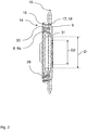
- Fig. 2 is the stamp cap 14 with the holding device 16 after Fig. 1 shown in detail. Particularly visible is the arrangement of the stamp cap 14 on the closure lid 15 of the caliper 2 ( Fig. 1 ).
- the holding device 16 is formed as a metal ring and is fixed to a common end 30 of the primary seal 8 and the secondary seal 9 in the stamp protection cap 14.
- the holding device 16 is used for shaping and stabilizing the stamp protection cap 14.
- the stamp cap 14 is pressed with the holding device 16, by means of the clamping force of the holding device 16, against an inner wall 29 of the closure lid 15 of the caliper 2.
- the connection of the stamp protection cap 14 with the closure lid 15 is achieved by a compression.
- the stamp cap 14 is thus non-positively connected to the closure lid 15 of the caliper 2.
- the formed as a knob 17 undercut 18 is arranged as an additional captive against a loosening of the stamp protection cap 14 of the closure lid 15 of the caliper 2 on the stamp protection cap 14.
- the annular bead 31 of the primary seal 8 is clearly visible.
- the primary seal 8 has a larger sealing diameter D in the disassembled state than the sealing diameter D2 of the secondary seal 9 in the disassembled state.
- FIG. 2a A detailed section of the nub 17 formed undercut 18 after Fig. 1 and Fig. 2 , shows Fig. 2a ,
- the nub 17 acts as a barb against slipping of the stamp protection cap 14.
- the nub 17 is supported on the closure lid 15 of the caliper 2 from.
- the common end 30 of the primary seal 8 and the secondary seal 9 has in the region of the inner wall 29 of the closure lid 15 has a corrugated structure, which minimizes slippage of the stamp protection cap 14 from the closure lid 15 of the caliper 2.
- Fig. 3 shows the punch cap 14 for a disc brake 1 after Fig. 1 without a holding device 16.
- the stamp protective cap 14 has a primary seal 8 designed as a bellows 8a and a secondary seal 9.
- the stamp protection cap 14 has an annular bead 33 at a common end 30 of the primary seal 8 and the secondary seal 9, and an annular bead 31 on the primary seal 8.
- the annular bead 31 of the primary seal 8 is fixed in a groove 32 of the adjusting spindle head 27.
- the secondary seal 9 is applied to a Stellspindelhals 28 of the adjusting spindle 12.
- the annular bead 33 of the common end 30 of the primary seal 8 and the secondary seal 9 is knotted in a circumferential groove 24 of the closure lid 15.
- the circumferential groove 24 of the closure lid 15 is formed as a V-shaped groove.
- Fig. 4 is the stamp cap 14 after Fig. 3 completely shown in cross-section.
- the orientation of the annular bead 33 of the common end 30 of the primary seal 8 and the secondary seal 9 can be seen.
- the sealing diameter D of the primary seal 8 is greater than the sealing diameter D2 of the secondary seal.
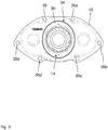
- Fig. 5 shows a closure cover 15 of the caliper 2 with an opening 34 for receiving a stamp protection cap 14 for a disc brake 1 after Fig. 1
- the opening 34 of the closure lid 15 of the caliper 2 has an oval profile.
- six boreholes 35, 35a, 35b, 35c, 35d, 35e are arranged on the caliper 2 along the closure lid 15 of the caliper 2.
- the closure cover 15 of the caliper 2 closes the passage opening 19 of the caliper 2 ( Fig. 1 ).
- the common end 30 of the stamp protection cap 14 is formed as an oval profile.
- the stamp protection cap 14 is arranged in the opening 34 of the closure lid 15 of the caliper 2.
- Fig. 6 shows a closure lid 15 of the caliper 2 after Fig. 5 for a disc brake after Fig. 1 ,
- the closure lid 15 of the caliper 2 has an opening 34 with a polygonal profile.
- the common end 30 of the stamp protection cap 14 is designed to fix the stamp protection cap 14 in the opening 34 of the closure lid 15 of the caliper 2 as a polygonal profile.
Landscapes
- Engineering & Computer Science (AREA)
- General Engineering & Computer Science (AREA)
- Mechanical Engineering (AREA)
- Braking Arrangements (AREA)
Abstract

Description
- Die Erfindung betrifft eine Scheibenbremse nach dem Oberbegriff von Anspruch 1. Scheibenbremsen mit einer Primärdichtung und einer Sekundärdichtung im Bereich einer Stellspindel sind hinlänglich bekannt. Die Primärdichtung und die Sekundärdichtung schützen den inneren Bereich eines Bremssattels vor Umwelteinflüssen wie Schnee, Regen, Staub oder Steinen. Insbesondere soll die Funktionalität der Bauteile der Scheibenbremse zum Zuspannen von Bremsbelägen aufrechterhalten bleiben. Beispielsweise ist für eine Nachstelleinrichtung ein Schutz vor Umwelteinflüssen erforderlich. Unter anderem umfasst die Nachstelleinrichtung eine axial in Richtung der Scheibenbremsenachse angeordnete Stellspindel zum Nachstellen der Bremsbeläge gegen die Bremsscheibe. Wenn die Funktionalität der Stellspindel eingeschränkt ist oder die Stellspindel bedingt durch Korrosion beschädigt ist, kann die Scheibenbremse nicht mehr den Verschleiß der Bremsbeläge kompensieren und das Lüftspiel konstant halten. Das Lüftspiel wird schleichend größer und es kommt folglich zu einem Bremskraft- und einem Bremsmomentverlust.
- Aus der
WO99/49242 A1 - Eine weitere Optimierung der Abdichtung des Innenraums vor Umwelteinflüssen geht aus der
DE102011011394 A1 hervor. Eine Dichtung ist ein als Primärdichtung ausgeführter Faltenbalg und eine zweite Dichtung ist eine zum Faltenbalg konzentrisch angeordnete Sekundärdichtung. Die Primärdichtung ist über ein Metallteil mit einem Kunststoffteil verbunden, welches eine als Dichtlippe ausgebildete Sekundärdichtung aufweist. Über das Kunststoffteil sind die Primärdichtung und die Sekundärdichtung mit dem Verschlussdeckel verbunden. - Die
DE102012006114 A1 beschreibt eine weitere Verbesserung der Abdichtung mittels einer Primärdichtung und einer Sekundärdichtung im Bereich der Stellspindel der Nachstellvorrichtung. Die Sekundärdichtung weist einen Gewindedichtring auf, der sich mit der Stellspindel der Nachstellvorrichtung dreht. Zudem weist die Sekundärdichtung eine nicht drehende Dichtmembran auf. Sowohl die Primärdichtung, als auch die Sekundärdichtung müssen einzeln an den Verschlussdeckel angebracht werden. - Eine weitere Möglichkeit der Abdichtung des Bremssattelinnenraums zeigt die
DE102007059777 A1 . Zur besseren Montage und Demontage ist eine Halteeinrichtung vorgesehen, die eine Sekundärdichtung hält und an der eine dritte Dichtung anliegt. Die Halteeinrichtung stützt sich an dem Druckbund ab. Eine Primärdichtung ist mit dem Stempel der Stellspindel und dem Verschlussdeckel verbunden. Im Falle einer undichten Primärdichtung schützen die Sekundärdichtung und die dritte Dichtung den Innenraum des Bremssattels vor Umwelteinflüssen. - Aufgabe der Erfindung ist es die
DE102007059777 A1 derart weiter zu entwickeln, dass der Innenraum des Bremssattels mit den sich innerhalb des Bremssattels angeordneten Bauteilen vor Umwelteinflüssen geschützt ist und die Montage oder Demontage der Primärdichtung und der Sekundärdichtung verbessert wird. Weiterhin ist es Aufgabe der Erfindung die Herstellung des Verschlussdeckels zu vereinfachen. - Die Aufgabe wird dadurch gelöst, dass eine Primärdichtung und eine Sekundärdichtung als Stempelschutzkappe ausgebildet sind. Das heißt, dass die Primärdichtung und die Sekundärdichtung keine eigenständigen Bauteile sind, die sich als Stempelschutzkappe zusammensetzen. Die Stempelschutzkappe ist vielmehr ein Bauteil das die Primärdichtung und der Sekundärdichtung umfasst. Bevorzugt bestehen die Primärdichtung und die Sekundärdichtung aus einem elastischen Material.
- In einer weiteren Ausgestaltung ist die Sekundärdichtung innerhalb eines Ringraums eines Bremssattels einer Scheibenbremse angeordnet und erfüllt somit die Dichtfunktion, falls die Primärdichtung beschädigt wird. Die Sekundärdichtung ist mit einem Ende mit der Stellspindel in Kontakt. Die Sekundärdichtung gleitet mit dem Ende, das mit der Stellspindel in Kontakt ist, während einer axialen Drehbewegung der Stellspindel in Richtung der Bremsscheibe oder entgegengesetzt der Bremsscheibe über die Stellspindel.
- Darüber hinaus ist in einer weiteren Ausgestaltung die Primärdichtung mit einem Dichtdurchmesser "D" an einem Stellspindelkopf der Stellspindel angeordnet und die Sekundärdichtung ist mit einem Dichtdurchmesser "D2" an einem Stellspindelhals der Stellspindel angeordnet. Der Dichtdurchmesser "D" der Primärdichtung kann größer oder kleiner sein als der Dichtdurchmesser "D2" der Sekundärdichtung. Es ist aber auch denkbar, dass der Dichtdurchmesser "D" der Primärdichtung und der Dichtdurchmesser "D2" der Sekundärdichtung gleich groß sind.
- Die Stempelschutzkappe ist in einer weiteren Ausgestaltung über eine Halteeinrichtung an einem Verschlussdeckel des Bremssattels angeordnet. Besonders vorteilhaft ist die Stempelschutzkappe über die Halteeinrichtung an dem Verschlussdeckel des Bremssattels kraftschlüssig angeordnet. Die Halteeinrichtung ist bevorzugt ein Metallprofil, welches im Querschnitt eine L-Form aufweist. Die Halteeinrichtung kann auch aus Kunststoff oder anderen Materialien bestehen.
- In einer weiteren Ausgestaltung weist die Stempelschutzkappe radial in Richtung des Verschlussdeckels des Bremssattels eine Hinterschneidung auf. Unter einer radialen Richtung ist eine quer zur Scheibenbremsenachse verlaufende Richtung zu verstehen. Die Hinterschneidung dient als zusätzliche Verliersicherung und zu einer Erhöhung der Auszugskräfte der Primärdichtung. Als Auszugskraft sind Demontagekräfte gemeint, die benötigt werden um die Stempelschutzkappe vom Deckel zu entfernen.
- Zumindest eine Noppe bildet die Hinterschneidung der Stempelschutzkappe in einer weiteren vorteilhaften Ausgestaltung Die zumindest eine Noppe ist bevorzugt aus dem gleichen Material wie die Primärdichtung und die Sekundärdichtung.
- Eine Öffnung des Verschlussdeckels des Bremssattels und/oder die Nut des Stellspindelkopfs und/oder der Stellspindelhals sind in einer weiteren Ausgestaltung als kreisförmiges Profil, als ovales Profil oder als Polygonprofil ausgebildet. Bevorzugt werden die Primärdichtung und die Sekundärdichtung auf einem kreisförmigen Profil aufgezogen.
- Darüber hinaus ist die Stempelschutzkappe in einer weiteren vorteilhaften Ausgestaltung direkt an dem Verschlussdeckel des Bremssattels angeordnet. Die Halteinrichtung wird nicht mehr benötigt, wodurch Montageschritte reduziert und Kosten eingespart werden.
- Ohne die Halteeinrichtung wird die Stempelschutzkappe in einer weiteren Ausgestaltung in einer umlaufenden Nut des Verschlussdeckels fixiert. Die umlaufende Nut des Verschlussdeckels weist eine V-Form oder eine U-Form auf. Die notwendige Vorspannung auf eine Ringwulst eines gemeinsamen Endes der Primärdichtung und der Sekundärdichtung der Stempelschutzkappe wird durch eine Änderung des Durchmessers der Ringwulst erzielt.
- In einer weiteren Ausführung ist die Stempelschutzkappe durch Aufvulkanisierung mit dem Verschlussdeckel fixiert. Unter einer Aufvulkanisierung ist eine thermoplastische Umformung zu verstehen. Durch die Aufvulkanisierung wird zwischen der Stempelschutzkappe und dem Verschlussdeckel eine stoffschlüssige Verbindung hergestellt.
- In einer weiteren Ausgestaltung ist die Stempelschutzkappe demontierbar. Die Stempelschutzkappe kann ausgetauscht werden. Beispielsweise kann eine beschädigte Stempelschutzkappe im Service gegen eine neue Stempelschutzkappe ersetzt werden.
- Außerdem ist die Primärdichtung in einer weiteren Ausgestaltung, bezogen auf die Scheibenbremsenachse, radial an dem Stellspindelkopf der Stellspindel angeordnet. Die Primärdichtung ist in Richtung der Scheibenbremsenachse beweglich.
- Darüber hinaus ist die Sekundärdichtung in einer weiteren Ausgestaltung im Querschnitt L-förmig ausgebildet.
- Die Primärdichtung ist in einer weiteren Ausgestaltung ein Faltenbalg. Während einer axialen Bewegung der Stellspindel in Richtung der Bremsscheibe entfaltet sich der Faltenbalg und faltet sich in einer der Bremsscheibe entgegengesetzten Richtung zusammen. Damit bleibt die Stellspindel vor Umwelteinflüssen vollständig geschützt.
- Vorteilhaft ist der Verschlussdeckel in einer weiteren Ausführung fertigungstechnisch aus einer Biegerichtung herstellbar. Als Biegerichtung ist die Richtung zu verstehen, aus der der Verschlussdeckel mit dem Bearbeitungswerkzeug bearbeitet wird. Der Verschlussdeckel muss während des Bearbeitungsvorgangs nicht mehr gewendet werden. Insbesondere wird die Form des Verschlussdeckels mit einem Stanzwerkzeug und einem Stempel hergestellt. Ein zweiter Montageschritt aus einer zweiten Biegerichtung ist nicht notwendig.
- Nachfolgend werden ausgewählte Ausführungsbeispiele der Erfindung anhand der beigefügten Figuren erläutert.
- Es zeigt:
-
Fig. 1 eine geschnittene Ansicht einer Scheibenbremse mit einer Stempelschutzkappe, -
Fig. 2 einen Querschnitt der Stempelschutzkappe mit einer Halteeinrichtung im Detail, -
Fig. 2a eine Detailansicht der Hinterschneidung einer Stempelschutzkappe gemäßFig. 1 undFig. 2 , -
Fig. 3 eine geschnittene Seitenansicht einer Stellspindel mit einer Stempelschutzkappe ohne eine Halteeinrichtung im eingebauten Zustand, -
Fig. 4 einen Querschnitt der Stempelschutzkappe ohne eine Halteeinrichtung, -
Fig. 5 einen Verschlussdeckel zur Aufnahme einer Stempelschutzkappe mit einem ovalen Profil, -
Fig. 6 einen Verschlussdeckel zur Aufnahme einer Stempelschutzkappe mit einem Polygonprofil. -
Fig. 1 zeigt eine geschnittene Seitenansicht einer Scheibenbremse 1 mit einem Bremssattel 2 und einer zwischen zwei Bremsbelägen 5, 5a angeordneten Bremsscheibe 37. Über einen Aktuator wird ein Betätigungshebel 4 axial in Richtung der Bremsscheibe 37 oder entgegengesetzt in Richtung der Bremsscheibe 37 bewegt. Aufgrund der Drehbewegung des Betätigungshebels 4 bewegt sich eine Stellspindel 12 axial in Richtung der Bremsscheibe 37 bis die Bremsbeläge 5, 5a an der Bremsscheibe 37 anliegen. Die Bremsbeläge 5, 5a lösen sich von der Bremsscheibe 37, wenn sich die Stellspindel 12 entgegengesetzt der Richtung der Bremsscheibe 37 bewegt. Die Stellspindel 12 ist innerhalb eines Innenraums 7 des Bremssattels 2, axial entlang einer Scheibenbremsenachse A, angeordnet und erstreckt sich, axial entlang der Scheibenbremsenachse A, durch einen Druckbund 13. Die Stellspindel 12, ein Stellspindelkopf 27 und der Druckbund 13 bilden eine Nachstelleinrichtung 36. Ein Ringraum 10 ist von einer Innenwand 6 einer Durchgangsöffnung 19 des Bremssattels 2 sowie der sich durch die Durchgangsöffnung 19 hindurchstreckenden Nachstelleinrichtung 36 begrenzt. An dem Bremssattel 2 ist in dem Bereich der Durchgangsöffnung 19 des Bremssattels 2 ein Verschlussdeckel 15 des Bremssattels 2 mit einer Stempelschutzkappe 14 angeordnet. Der Verschlussdeckel 15 des Bremssattels 2 weist eine Öffnung 34 (Fig. 5 ) auf, wobei die Stempelschutzkappe 14 in der Öffnung 34 angeordnet ist. Die Stempelschutzkappe 14 weist eine Primärdichtung 8, eine Sekundärdichtung 9 und eine Halteeinrichtung 16 auf. Die Primärdichtung 8 ist als Faltenbalg 8a ausgebildet und weist an einem Ende eine Ringwulst 31 auf, die in einer Nut 32 des Stellspindelkopfs 27 der Stellspindel 12 befestigt ist. Der Faltenbalg 8a bewegt sich mit der Stellspindel 12 in axialer Richtung der Scheibenbremsenachse A. Die Sekundärdichtung 9 liegt an einem Stellspindelhals 28 der Stellspindel 12 an. Zusätzlich weist die Stempelschutzkappe 14 eine als Noppe 17 ausgebildete Hinterschneidung 18 auf. - In
Fig. 2 ist die Stempelschutzkappe 14 mit der Halteeinrichtung 16 nachFig. 1 im Detail gezeigt. Besonders gut sichtbar ist die Anordnung der Stempelschutzkappe 14 an dem Verschlussdeckel 15 des Bremssattels 2 (Fig. 1 ). Die Halteeinrichtung 16 ist als Metallring ausgebildet und ist an einem gemeinsamen Ende 30 der Primärdichtung 8 und der Sekundärdichtung 9 in der Stempelschutzkappe 14 fixiert. Die Halteeinrichtung 16 dient zur Formgebung und Stabilisierung der Stempelschutzkappe 14. Die Stempelschutzkappe 14 wird mit der Halteeinrichtung 16, mittels der Spannkraft der Halteeinrichtung 16, gegen eine Innenwand 29 des Verschlussdeckels 15 des Bremssattels 2 gedrückt. Die Verbindung der Stempelschutzkappe 14 mit dem Verschlussdeckel 15 wird durch eine Verpressung erziehlt. Die Stempelschutzkappe 14 ist damit kraftschlüssig mit dem Verschlussdeckel 15 des Bremssattels 2 verbunden. Die als Noppe 17 ausgebildete Hinterschneidung 18 ist als zusätzliche Verliersicherung gegen ein Lösen der Stempelschutzkappe 14 von dem Verschlussdeckel 15 des Bremssattels 2 an der Stempelschutzkappe 14 angeordnet. Darüber hinaus ist die Ringwulst 31 der Primärdichtung 8 gut sichtbar. Die Primärdichtung 8 weist im ausgebauten Zustand einen größeren Dichtdurchmesser D auf, als der Dichtdurchmesser D2 der Sekundärdichtung 9 im ausgebauten Zustand. - Einen detaillierten Ausschnitt der als Noppe 17 ausgebildeten Hinterschneidung 18 nach
Fig. 1 undFig. 2 , zeigtFig. 2a .
Die Noppe 17 wirkt als Widerhaken gegen ein Verrutschen der Stempelschutzkappe 14. Die Noppe 17 stützt sich an dem Verschlussdeckel 15 des Bremssattels 2 ab. Das gemeinsames Ende 30 der Primärdichtung 8 und der Sekundärdichtung 9 weist im Bereich der Innenwand 29 des Verschlussdeckels 15 eine gewellte Struktur auf, die ein Verrutschen der Stempelschutzkappe 14 aus dem Verschlussdeckel 15 des Bremssattels 2 minimiert.
Fig. 3 zeigt die Stempelschutzkappe 14 für eine Scheibenbremse 1 nachFig. 1 ohne eine Halteeinrichtung 16. Die Stempelschutzkappe 14 weist eine als Faltenbalg 8a ausgestaltete Primärdichtung 8 und eine Sekundärdichtung 9 auf. Zusätzlich weist die Stempelschutzkappe 14 eine Ringwulst 33 an einem gemeinsamen Ende 30 der Primärdichtung 8 und der Sekundärdichtung 9, sowie eine Ringwulst 31 an der Primärdichtung 8 auf. Die Ringwulst 31 der Primärdichtung 8 ist in einer Nut 32 des Stellspindelkopfs 27 fixiert. Die Sekundärdichtung 9 liegt an einem Stellspindelhals 28 der Stellspindel 12 an. Die Ringwulst 33 des gemeinsamen Endes 30 der Primärdichtung 8 und der Sekundärdichtung 9 ist in einer umlaufenden Nut 24 des Verschlussdeckels 15 eingeknüpft. Die umlaufende Nut 24 des Verschlussdeckels 15 ist als V-förmige Nut ausgebildet. - In
Fig. 4 ist die Stempelschutzkappe 14 nachFig. 3 vollständig im Querschnitt gezeigt. Insbesondere ist die Ausrichtung der Ringwulst 33 des gemeinsamen Endes 30 der Primärdichtung 8 und der Sekundärdichtung 9 erkennbar. Zudem veranschaulichtFig. 4 , dass der Dichtdurchmesser D der Primärdichtung 8 größer ist, als der Dichtdurchmesser D2 der Sekundärdichtung. -
Fig. 5 zeigt einen Verschlussdeckel 15 des Bremssattels 2 mit einer Öffnung 34 zur Aufnahme einer Stempelschutzkappe 14 für eine Scheibenbremse 1 nachFig. 1 . Die Öffnung 34 des Verschlussdeckels 15 des Bremssattels 2 weist ein ovales Profil auf. Zur Fixierung des Verschlussdeckels 15 des Bremssattels 2 sind an dem Bremssattel 2 entlang des Verschlussdeckels 15 des Bremssattels 2 sechs Bohrlöcher 35, 35a, 35b, 35c, 35d, 35e angeordnet. Der Verschlussdeckel 15 des Bremssattels 2 schließt die Durchgangsöffnung 19 des Bremssattels 2 (Fig. 1 ). Das gemeinsame Ende 30 der Stempelschutzkappe 14 ist als ovales Profil ausgebildet. Die Stempelschutzkappe 14 ist in der Öffnung 34 des Verschlussdeckels 15 des Bremssattels 2 angeordnet. -
Fig. 6 zeigt einen Verschlussdeckel 15 des Bremssattels 2 nachFig. 5 für eine Scheibenbremse nachFig. 1 . InFig. 6 weist der Verschlussdeckel 15 des Bremssattels 2 eine Öffnung 34 mit einem Polygonprofil auf. Das gemeinsame Ende 30 der Stempelschutzkappe 14 ist zur Fixierung der Stempelschutzkappe 14 in der Öffnung 34 des Verschlussdeckels 15 des Bremssattels 2 auch als Polygonprofil ausgebildet. -
- 1
- Scheibenbremse
- 2
- Bremssattel
- 4
- Betätigungshebel
- 5, 5a
- Bremsbelag
- 6
- Innenwand einer Durchgangsöffnung 19
- 7
- Innenraum des Bremssattels 2
- 8
- Primärdichtung
- 8a
- Faltenbalg
- 9
- Sekundärdichtung
- 10
- Ringraum
- 12
- Stellspindel
- 13
- Druckbund
- 14
- Stempelschutzkappe
- 15
- Verschlussdeckel des Bremssattels 2
- 16
- Halteeinrichtung
- 17
- Noppe
- 18
- Hinterschneidung
- 19
- Durchgangsöffnung des Bremssattels 2
- 24
- umlaufende Nut des Verschlussdeckels 15
- 27
- Stellspindelkopf
- 28
- Stellspindelhals
- 29
- Innenwand des Verschlussdeckels 15 des Bremssattels 2
- 30
- gemeinsames Ende der Primärdichtung 8 und der Sekundärdichtung 9
- 31
- Ringwulst der Primärdichtung 8
- 32
- Nut des Stellspindelkopfs 27
- 33
- Ringwulst des gemeinsamen Ende 30 der Primärdichtung 8 und der Sekundärdichtung 9
- 34
- Öffnung des Verschlussdeckels 15 des Bremssattels 2
- 35 - 35e
- Bohrlöcher des Verschlussdeckels des Bremssattels 2
- 36
- Nachstelleinrichtung
- 37
- Bremsscheibe
- A
- Scheibenbremsenachse
- D
- Dichtdurchmesser der Primärdichtung 8
- D2
- Dichtdurchmesser der Sekundärdichtung 9
Claims (15)
- Scheibenbremse (1) für Nutzfahrzeuge mit einem Bremssattel (2), einer Bremsscheibe (37), einem axial zu einer Scheibenbremsenachse (A) der Bremsscheibe (37) angeordneten Betätigungshebel (4), einer Nachstelleinrichtung (36) umfassend eine Stellspindel (12), einen Druckbund (13) und einen Stellspindelkopf (27), wobei die Nachstelleinrichtung (36) zumindest teilweise innerhalb eines Innenraums (7) des Bremssattels (2) angeordnet ist, einer Primärdichtung (8) zum Abdichten des Innenraums 7 des Bremssattels 2, einem Ringraum (10), der von einer Innenwand (6) einer Durchgangsöffnung (19) des Bremssattels (2) und der Nachstelleinrichtung begrenzt ist und einer Sekundärdichtung (9) zum zumindest teilweise Abdichten des Innenraums (7) des Bremssattels (2), dadurch gekennzeichnet, dass die Primärdichtung (8) und die Sekundärdichtung (9) als Stempelschutzkappe (14) ausgebildet sind.
- Scheibenbremse (1) für Nutzfahrzeuge nach Anspruch 1, dadurch gekennzeichnet, dass die Sekundärdichtung (9) innerhalb des Ringraums (10) angeordnet ist.
- Scheibenbremse (1) für Nutzfahrzeuge nach Anspruch 1 oder 2, dadurch gekennzeichnet, dass die Primärdichtung (8) mit einem Dichtdurchmesser (D) an dem Stellspindelkopf (27) angeordnet ist und die Sekundärdichtung (9) mit einem Dichtdurchmesser (D2) an einem Stellspindelhals (28) der Stellspindel (12) angeordnet ist.
- Scheibenbremse (1) für Nutzfahrzeuge nach einem der vorangegangenen Ansprüche, dadurch gekennzeichnet, dass die Stempelschutzkappe (14) über eine Halteeinrichtung (16) an einem Verschlussdeckel (15) des Bremssattels (2) angeordnet ist.
- Scheibenbremse (1) für Nutzfahrzeuge nach einem der vorangegangenen Ansprüche, dadurch gekennzeichnet, dass die Stempelschutzkappe (14) radial in Richtung des Verschlussdeckels (15) des Bremssattels (2) eine Hinterschneidung (18) aufweist.
- Scheibenbremse (1) für Nutzfahrzeuge nach Anspruch 5, dadurch gekennzeichnet, dass zumindest eine Noppe (17) die Hinterschneidung (18) der Stempelschutzkappe (14) bildet.
- Scheibenbremse (1) für Nutzfahrzeuge nach einem der Ansprüche 4 bis 6, dadurch gekennzeichnet, dass eine Öffnung (34) des Verschlussdeckels (15) des Bremssattels (2) und/oder die Nut (32) des Stellspindelkopfs (27) und/oder der Stellspindelhals (28) als kreisförmiges Profil, als ovales Profil oder als Polygonprofil ausgebildet sind.
- Scheibenbremse (1) für Nutzfahrzeuge nach einem der Ansprüche 4 bis 7, dadurch gekennzeichnet, dass die Stempelschutzkappe (14) direkt an dem Verschlussdeckel (15) des Bremssattels (2) angeordnet ist.
- Scheibenbremse für Nutzfahrzeuge nach einem der Ansprüche 4 bis 8, dadurch gekennzeichnet, dass die Stempelschutzkappe (14) in einer umlaufenden Nut (24) des Verschlussdeckels (15) fixiert ist.
- Scheibenbremse für Nutzfahrzeuge nach einem der Ansprüche 4 bis 9, dadurch gekennzeichnet, dass die Stempelschutzkappe (14) durch Aufvulkanisierung an dem Verschlussdeckel (15) fixiert ist.
- Scheibenbremse (1) für Nutzfahrzeuge nach einem der vorangegangenen Ansprüche, dadurch gekennzeichnet, dass die Stempelschutzkappe (14) demontierbar ist.
- Scheibenbremse (1) für Nutzfahrzeuge nach einem der vorangegangenen Ansprüche, dadurch gekennzeichnet, dass die Primärdichtung (8), bezogen auf die Scheibenbremsenachse (A), radial an dem Stellspindelkopf (27) der Stellspindel (12) angeordnet ist und die Primärdichtung (8) in Richtung der Scheibenbremsenachse (A) beweglich ist.
- Scheibenbremse (1) für Nutzfahrzeuge nach einem der vorangegangenen Ansprüche, dadurch gekennzeichnet, dass die Sekundärdichtung (9) im Querschnitt L-förmig ausgebildet ist.
- Scheibenbremse (1) für Nutzfahrzeuge nach einem der vorangegangenen Ansprüche, dadurch gekennzeichnet, dass die Primärdichtung (8) ein Faltenbalg (8a) ist.
- Scheibenbremse (1) für Nutzfahrzeuge nach einem der Ansprüche 4 bis 14, dadurch gekennzeichnet, dass der Verschlussdeckel (15) fertigungstechnisch aus einer Biegerichtung herstellbar ist.
Priority Applications (4)
| Application Number | Priority Date | Filing Date | Title |
|---|---|---|---|
| EP18151103.1A EP3511589B1 (de) | 2018-01-10 | 2018-01-10 | Scheibenbremse für nutzfahrzeuge |
| PCT/EP2018/085764 WO2019137768A1 (de) | 2018-01-10 | 2018-12-19 | Scheibenbremse für nutzfahrzeuge |
| CN201880083371.7A CN111512061B (zh) | 2018-01-10 | 2018-12-19 | 用于商用车辆的盘式制动器 |
| US16/961,372 US11320012B2 (en) | 2018-01-10 | 2018-12-19 | Disc brake for utility vehicles |
Applications Claiming Priority (1)
| Application Number | Priority Date | Filing Date | Title |
|---|---|---|---|
| EP18151103.1A EP3511589B1 (de) | 2018-01-10 | 2018-01-10 | Scheibenbremse für nutzfahrzeuge |
Publications (2)
| Publication Number | Publication Date |
|---|---|
| EP3511589A1 true EP3511589A1 (de) | 2019-07-17 |
| EP3511589B1 EP3511589B1 (de) | 2020-08-19 |
Family
ID=60954914
Family Applications (1)
| Application Number | Title | Priority Date | Filing Date |
|---|---|---|---|
| EP18151103.1A Active EP3511589B1 (de) | 2018-01-10 | 2018-01-10 | Scheibenbremse für nutzfahrzeuge |
Country Status (4)
| Country | Link |
|---|---|
| US (1) | US11320012B2 (de) |
| EP (1) | EP3511589B1 (de) |
| CN (1) | CN111512061B (de) |
| WO (1) | WO2019137768A1 (de) |
Families Citing this family (3)
| Publication number | Priority date | Publication date | Assignee | Title |
|---|---|---|---|---|
| DE102017104442A1 (de) * | 2017-03-03 | 2018-09-06 | Knorr-Bremse Systeme für Nutzfahrzeuge GmbH | Faltenbalg sowie mindestens einen Faltenbalg aufweisende Scheibenbremse |
| DE102023105632A1 (de) * | 2023-03-07 | 2024-09-12 | Knorr-Bremse Systeme für Nutzfahrzeuge GmbH | Scheibenbremse für Nutzfahrzeuge |
| DE102024128046A1 (de) * | 2024-09-27 | 2026-04-02 | Knorr-Bremse Systeme für Nutzfahrzeuge GmbH | Scheibenbremse für ein Nutzfahrzeug |
Citations (7)
| Publication number | Priority date | Publication date | Assignee | Title |
|---|---|---|---|---|
| WO1999049242A1 (en) | 1998-03-26 | 1999-09-30 | Meritor Heavy Vehicle Braking Systems (Uk) Limited | Disc brake seal assembly |
| DE102007059777A1 (de) | 2007-12-12 | 2009-06-25 | Wabco Radbremsen Gmbh | Pneumatisch und/oder elektromechanisch betätigbare Nutzfahrzeugscheibenbremse |
| EP2444698A1 (de) * | 2010-10-22 | 2012-04-25 | KNORR-BREMSE Systeme für Nutzfahrzeuge GmbH | Scheibenbremse |
| DE102011011394A1 (de) | 2011-02-17 | 2012-08-23 | Knorr-Bremse Systeme für Nutzfahrzeuge GmbH | Scheibenbremse |
| US20120325595A1 (en) * | 2011-06-22 | 2012-12-27 | Meritor Heavy Vehicle Braking Systems (Uk) Limited | Force transmission device |
| DE102012006114A1 (de) | 2012-03-26 | 2013-09-26 | Knorr-Bremse Systeme für Nutzfahrzeuge GmbH | Scheibenbremse |
| DE102013006859A1 (de) * | 2013-04-19 | 2014-10-23 | Knorr-Bremse Systeme für Nutzfahrzeuge GmbH | Scheibenbremse für ein Nutzfahrzeug |
Family Cites Families (7)
| Publication number | Priority date | Publication date | Assignee | Title |
|---|---|---|---|---|
| BR8000881A (pt) * | 1979-02-14 | 1980-10-21 | Kelsey Hayes Co | Ajustador de folga,mecanismo de freio e acionador de freio de calibre |
| JPS58142449U (ja) * | 1982-03-19 | 1983-09-26 | トヨタ自動車株式会社 | ブ−ツ |
| JPS58142450U (ja) * | 1982-03-19 | 1983-09-26 | アイシン精機株式会社 | ブ−ツ |
| SE516495C2 (sv) * | 2000-05-31 | 2002-01-22 | Haldex Brake Prod Ab | Bromsmekanism och bromsok för en skivbroms |
| SE516513C2 (sv) * | 2000-05-31 | 2002-01-22 | Haldex Brake Prod Ab | Skivbroms innefattande en bromsmekanism |
| DE102006040754B3 (de) * | 2006-08-31 | 2008-03-27 | Knorr-Bremse Systeme für Nutzfahrzeuge GmbH | Scheibenbremse, insbesondere für ein Nutzfahrzeug |
| DE102013015002A1 (de) * | 2013-09-10 | 2015-03-12 | Wabco Europe Bvba | Scheibenbremse, insbesondere für Nutzfahrzeuge |
-
2018
- 2018-01-10 EP EP18151103.1A patent/EP3511589B1/de active Active
- 2018-12-19 US US16/961,372 patent/US11320012B2/en active Active
- 2018-12-19 CN CN201880083371.7A patent/CN111512061B/zh active Active
- 2018-12-19 WO PCT/EP2018/085764 patent/WO2019137768A1/de not_active Ceased
Patent Citations (7)
| Publication number | Priority date | Publication date | Assignee | Title |
|---|---|---|---|---|
| WO1999049242A1 (en) | 1998-03-26 | 1999-09-30 | Meritor Heavy Vehicle Braking Systems (Uk) Limited | Disc brake seal assembly |
| DE102007059777A1 (de) | 2007-12-12 | 2009-06-25 | Wabco Radbremsen Gmbh | Pneumatisch und/oder elektromechanisch betätigbare Nutzfahrzeugscheibenbremse |
| EP2444698A1 (de) * | 2010-10-22 | 2012-04-25 | KNORR-BREMSE Systeme für Nutzfahrzeuge GmbH | Scheibenbremse |
| DE102011011394A1 (de) | 2011-02-17 | 2012-08-23 | Knorr-Bremse Systeme für Nutzfahrzeuge GmbH | Scheibenbremse |
| US20120325595A1 (en) * | 2011-06-22 | 2012-12-27 | Meritor Heavy Vehicle Braking Systems (Uk) Limited | Force transmission device |
| DE102012006114A1 (de) | 2012-03-26 | 2013-09-26 | Knorr-Bremse Systeme für Nutzfahrzeuge GmbH | Scheibenbremse |
| DE102013006859A1 (de) * | 2013-04-19 | 2014-10-23 | Knorr-Bremse Systeme für Nutzfahrzeuge GmbH | Scheibenbremse für ein Nutzfahrzeug |
Also Published As
| Publication number | Publication date |
|---|---|
| WO2019137768A1 (de) | 2019-07-18 |
| US11320012B2 (en) | 2022-05-03 |
| EP3511589B1 (de) | 2020-08-19 |
| CN111512061A (zh) | 2020-08-07 |
| CN111512061B (zh) | 2022-05-24 |
| US20200347898A1 (en) | 2020-11-05 |
Similar Documents
| Publication | Publication Date | Title |
|---|---|---|
| DE19915022B4 (de) | Elastomerdichtung zwischen einem Kolben und einem Zylinder und/oder einem Schaft eines automatischen Kraftfahrzeuggetriebes | |
| EP0133928B1 (de) | Radialwellendichtring | |
| DE102011011394B4 (de) | Scheibenbremse | |
| DE202010000254U1 (de) | Reifenventil | |
| EP2059691A1 (de) | Scheibenbremse, insbesondere für ein nutzfahrzeug | |
| EP3511589B1 (de) | Scheibenbremse für nutzfahrzeuge | |
| EP3682974B1 (de) | Vorrichtung zum ausgeben eines fliessfähigen mediums | |
| EP3662174A1 (de) | Bremsscheibe und verfahren zur herstellung einer bremsscheibe | |
| EP3026286A2 (de) | Scheibenbremse für ein nutzfahrzeug | |
| DE102010030277A1 (de) | Kolben zur verdrehgesicherten Anordnung in einem Bremssattel | |
| WO2013143980A1 (de) | Scheibenbremse, insbesondere für ein nutzfahrzeug | |
| DE102012006114A1 (de) | Scheibenbremse | |
| EP3128198A2 (de) | Hydraulikzylinder, insbesondere nehmerzylinder für eine hydraulische kupplungsbetätigung für kraftfahrzeuge | |
| DE102016002947B4 (de) | Dehnspanneinrichtung | |
| DE102008024163B4 (de) | Verbundkolben für ein Kraftfahrzeuggetriebe | |
| EP3853493B1 (de) | Scheibenbremse mit einer blechanordnung für ein fahrzeug sowie blechanordnung für eine scheibenbremse | |
| EP2469118B1 (de) | Scheibenbremse | |
| DE102011006029A1 (de) | Dichtungsanordnung für nasslaufende Doppelkupplung | |
| EP2306040B1 (de) | Scheibenbremse und Führungsholm einer Scheibenbremse | |
| DE102016112265A1 (de) | Scheibenbremse für ein Nutzfahrzeug | |
| DE69710176T2 (de) | Nehmerzylinder für die hydraulische betätigung einer kraftfahrzeugkupplung | |
| DE3203374C2 (de) | Sitzring für ein Klappenventil | |
| EP4038291B1 (de) | Bremsstempel einer scheibenbremse eines nutzfahrzeugs und scheibenbremse | |
| EP1841981B1 (de) | Scheibenbremse | |
| EP3247918B1 (de) | Kupplungssystem |
Legal Events
| Date | Code | Title | Description |
|---|---|---|---|
| PUAI | Public reference made under article 153(3) epc to a published international application that has entered the european phase |
Free format text: ORIGINAL CODE: 0009012 |
|
| STAA | Information on the status of an ep patent application or granted ep patent |
Free format text: STATUS: THE APPLICATION HAS BEEN PUBLISHED |
|
| AK | Designated contracting states |
Kind code of ref document: A1 Designated state(s): AL AT BE BG CH CY CZ DE DK EE ES FI FR GB GR HR HU IE IS IT LI LT LU LV MC MK MT NL NO PL PT RO RS SE SI SK SM TR |
|
| AX | Request for extension of the european patent |
Extension state: BA ME |
|
| STAA | Information on the status of an ep patent application or granted ep patent |
Free format text: STATUS: REQUEST FOR EXAMINATION WAS MADE |
|
| 17P | Request for examination filed |
Effective date: 20200117 |
|
| RBV | Designated contracting states (corrected) |
Designated state(s): AL AT BE BG CH CY CZ DE DK EE ES FI FR GB GR HR HU IE IS IT LI LT LU LV MC MK MT NL NO PL PT RO RS SE SI SK SM TR |
|
| GRAP | Despatch of communication of intention to grant a patent |
Free format text: ORIGINAL CODE: EPIDOSNIGR1 |
|
| STAA | Information on the status of an ep patent application or granted ep patent |
Free format text: STATUS: GRANT OF PATENT IS INTENDED |
|
| INTG | Intention to grant announced |
Effective date: 20200608 |
|
| GRAS | Grant fee paid |
Free format text: ORIGINAL CODE: EPIDOSNIGR3 |
|
| GRAA | (expected) grant |
Free format text: ORIGINAL CODE: 0009210 |
|
| STAA | Information on the status of an ep patent application or granted ep patent |
Free format text: STATUS: THE PATENT HAS BEEN GRANTED |
|
| AK | Designated contracting states |
Kind code of ref document: B1 Designated state(s): AL AT BE BG CH CY CZ DE DK EE ES FI FR GB GR HR HU IE IS IT LI LT LU LV MC MK MT NL NO PL PT RO RS SE SI SK SM TR |
|
| REG | Reference to a national code |
Ref country code: CH Ref legal event code: EP |
|
| REG | Reference to a national code |
Ref country code: DE Ref legal event code: R096 Ref document number: 502018002195 Country of ref document: DE |
|
| REG | Reference to a national code |
Ref country code: AT Ref legal event code: REF Ref document number: 1304271 Country of ref document: AT Kind code of ref document: T Effective date: 20200915 |
|
| REG | Reference to a national code |
Ref country code: IE Ref legal event code: FG4D Free format text: LANGUAGE OF EP DOCUMENT: GERMAN |
|
| REG | Reference to a national code |
Ref country code: LT Ref legal event code: MG4D |
|
| REG | Reference to a national code |
Ref country code: NL Ref legal event code: MP Effective date: 20200819 |
|
| PG25 | Lapsed in a contracting state [announced via postgrant information from national office to epo] |
Ref country code: PT Free format text: LAPSE BECAUSE OF FAILURE TO SUBMIT A TRANSLATION OF THE DESCRIPTION OR TO PAY THE FEE WITHIN THE PRESCRIBED TIME-LIMIT Effective date: 20201221 Ref country code: NO Free format text: LAPSE BECAUSE OF FAILURE TO SUBMIT A TRANSLATION OF THE DESCRIPTION OR TO PAY THE FEE WITHIN THE PRESCRIBED TIME-LIMIT Effective date: 20201119 Ref country code: FI Free format text: LAPSE BECAUSE OF FAILURE TO SUBMIT A TRANSLATION OF THE DESCRIPTION OR TO PAY THE FEE WITHIN THE PRESCRIBED TIME-LIMIT Effective date: 20200819 Ref country code: LT Free format text: LAPSE BECAUSE OF FAILURE TO SUBMIT A TRANSLATION OF THE DESCRIPTION OR TO PAY THE FEE WITHIN THE PRESCRIBED TIME-LIMIT Effective date: 20200819 Ref country code: GR Free format text: LAPSE BECAUSE OF FAILURE TO SUBMIT A TRANSLATION OF THE DESCRIPTION OR TO PAY THE FEE WITHIN THE PRESCRIBED TIME-LIMIT Effective date: 20201120 Ref country code: HR Free format text: LAPSE BECAUSE OF FAILURE TO SUBMIT A TRANSLATION OF THE DESCRIPTION OR TO PAY THE FEE WITHIN THE PRESCRIBED TIME-LIMIT Effective date: 20200819 Ref country code: SE Free format text: LAPSE BECAUSE OF FAILURE TO SUBMIT A TRANSLATION OF THE DESCRIPTION OR TO PAY THE FEE WITHIN THE PRESCRIBED TIME-LIMIT Effective date: 20200819 Ref country code: BG Free format text: LAPSE BECAUSE OF FAILURE TO SUBMIT A TRANSLATION OF THE DESCRIPTION OR TO PAY THE FEE WITHIN THE PRESCRIBED TIME-LIMIT Effective date: 20201119 |
|
| PG25 | Lapsed in a contracting state [announced via postgrant information from national office to epo] |
Ref country code: IS Free format text: LAPSE BECAUSE OF FAILURE TO SUBMIT A TRANSLATION OF THE DESCRIPTION OR TO PAY THE FEE WITHIN THE PRESCRIBED TIME-LIMIT Effective date: 20201219 Ref country code: NL Free format text: LAPSE BECAUSE OF FAILURE TO SUBMIT A TRANSLATION OF THE DESCRIPTION OR TO PAY THE FEE WITHIN THE PRESCRIBED TIME-LIMIT Effective date: 20200819 Ref country code: LV Free format text: LAPSE BECAUSE OF FAILURE TO SUBMIT A TRANSLATION OF THE DESCRIPTION OR TO PAY THE FEE WITHIN THE PRESCRIBED TIME-LIMIT Effective date: 20200819 Ref country code: RS Free format text: LAPSE BECAUSE OF FAILURE TO SUBMIT A TRANSLATION OF THE DESCRIPTION OR TO PAY THE FEE WITHIN THE PRESCRIBED TIME-LIMIT Effective date: 20200819 Ref country code: PL Free format text: LAPSE BECAUSE OF FAILURE TO SUBMIT A TRANSLATION OF THE DESCRIPTION OR TO PAY THE FEE WITHIN THE PRESCRIBED TIME-LIMIT Effective date: 20200819 |
|
| PG25 | Lapsed in a contracting state [announced via postgrant information from national office to epo] |
Ref country code: EE Free format text: LAPSE BECAUSE OF FAILURE TO SUBMIT A TRANSLATION OF THE DESCRIPTION OR TO PAY THE FEE WITHIN THE PRESCRIBED TIME-LIMIT Effective date: 20200819 Ref country code: RO Free format text: LAPSE BECAUSE OF FAILURE TO SUBMIT A TRANSLATION OF THE DESCRIPTION OR TO PAY THE FEE WITHIN THE PRESCRIBED TIME-LIMIT Effective date: 20200819 Ref country code: DK Free format text: LAPSE BECAUSE OF FAILURE TO SUBMIT A TRANSLATION OF THE DESCRIPTION OR TO PAY THE FEE WITHIN THE PRESCRIBED TIME-LIMIT Effective date: 20200819 Ref country code: CZ Free format text: LAPSE BECAUSE OF FAILURE TO SUBMIT A TRANSLATION OF THE DESCRIPTION OR TO PAY THE FEE WITHIN THE PRESCRIBED TIME-LIMIT Effective date: 20200819 Ref country code: SM Free format text: LAPSE BECAUSE OF FAILURE TO SUBMIT A TRANSLATION OF THE DESCRIPTION OR TO PAY THE FEE WITHIN THE PRESCRIBED TIME-LIMIT Effective date: 20200819 |
|
| REG | Reference to a national code |
Ref country code: DE Ref legal event code: R097 Ref document number: 502018002195 Country of ref document: DE |
|
| RAP4 | Party data changed (patent owner data changed or rights of a patent transferred) |
Owner name: ZF CV SYSTEMS EUROPE BV |
|
| PG25 | Lapsed in a contracting state [announced via postgrant information from national office to epo] |
Ref country code: ES Free format text: LAPSE BECAUSE OF FAILURE TO SUBMIT A TRANSLATION OF THE DESCRIPTION OR TO PAY THE FEE WITHIN THE PRESCRIBED TIME-LIMIT Effective date: 20200819 Ref country code: AL Free format text: LAPSE BECAUSE OF FAILURE TO SUBMIT A TRANSLATION OF THE DESCRIPTION OR TO PAY THE FEE WITHIN THE PRESCRIBED TIME-LIMIT Effective date: 20200819 |
|
| PLBE | No opposition filed within time limit |
Free format text: ORIGINAL CODE: 0009261 |
|
| STAA | Information on the status of an ep patent application or granted ep patent |
Free format text: STATUS: NO OPPOSITION FILED WITHIN TIME LIMIT |
|
| PG25 | Lapsed in a contracting state [announced via postgrant information from national office to epo] |
Ref country code: SK Free format text: LAPSE BECAUSE OF FAILURE TO SUBMIT A TRANSLATION OF THE DESCRIPTION OR TO PAY THE FEE WITHIN THE PRESCRIBED TIME-LIMIT Effective date: 20200819 |
|
| 26N | No opposition filed |
Effective date: 20210520 |
|
| PG25 | Lapsed in a contracting state [announced via postgrant information from national office to epo] |
Ref country code: IT Free format text: LAPSE BECAUSE OF FAILURE TO SUBMIT A TRANSLATION OF THE DESCRIPTION OR TO PAY THE FEE WITHIN THE PRESCRIBED TIME-LIMIT Effective date: 20200819 |
|
| PG25 | Lapsed in a contracting state [announced via postgrant information from national office to epo] |
Ref country code: SI Free format text: LAPSE BECAUSE OF FAILURE TO SUBMIT A TRANSLATION OF THE DESCRIPTION OR TO PAY THE FEE WITHIN THE PRESCRIBED TIME-LIMIT Effective date: 20200819 Ref country code: MC Free format text: LAPSE BECAUSE OF FAILURE TO SUBMIT A TRANSLATION OF THE DESCRIPTION OR TO PAY THE FEE WITHIN THE PRESCRIBED TIME-LIMIT Effective date: 20200819 |
|
| REG | Reference to a national code |
Ref country code: CH Ref legal event code: PL |
|
| REG | Reference to a national code |
Ref country code: DE Ref legal event code: R081 Ref document number: 502018002195 Country of ref document: DE Owner name: ZF CV SYSTEMS EUROPE BV, BE Free format text: FORMER OWNER: WABCO EUROPE BVBA, BRUESSEL, BE |
|
| PG25 | Lapsed in a contracting state [announced via postgrant information from national office to epo] |
Ref country code: LU Free format text: LAPSE BECAUSE OF NON-PAYMENT OF DUE FEES Effective date: 20210110 |
|
| REG | Reference to a national code |
Ref country code: BE Ref legal event code: MM Effective date: 20210131 |
|
| PG25 | Lapsed in a contracting state [announced via postgrant information from national office to epo] |
Ref country code: LI Free format text: LAPSE BECAUSE OF NON-PAYMENT OF DUE FEES Effective date: 20210131 Ref country code: CH Free format text: LAPSE BECAUSE OF NON-PAYMENT OF DUE FEES Effective date: 20210131 |
|
| PG25 | Lapsed in a contracting state [announced via postgrant information from national office to epo] |
Ref country code: IE Free format text: LAPSE BECAUSE OF NON-PAYMENT OF DUE FEES Effective date: 20210110 |
|
| PG25 | Lapsed in a contracting state [announced via postgrant information from national office to epo] |
Ref country code: BE Free format text: LAPSE BECAUSE OF NON-PAYMENT OF DUE FEES Effective date: 20210131 |
|
| PG25 | Lapsed in a contracting state [announced via postgrant information from national office to epo] |
Ref country code: CY Free format text: LAPSE BECAUSE OF FAILURE TO SUBMIT A TRANSLATION OF THE DESCRIPTION OR TO PAY THE FEE WITHIN THE PRESCRIBED TIME-LIMIT Effective date: 20200819 |
|
| P01 | Opt-out of the competence of the unified patent court (upc) registered |
Effective date: 20230528 |
|
| PG25 | Lapsed in a contracting state [announced via postgrant information from national office to epo] |
Ref country code: HU Free format text: LAPSE BECAUSE OF FAILURE TO SUBMIT A TRANSLATION OF THE DESCRIPTION OR TO PAY THE FEE WITHIN THE PRESCRIBED TIME-LIMIT; INVALID AB INITIO Effective date: 20180110 |
|
| REG | Reference to a national code |
Ref country code: AT Ref legal event code: MM01 Ref document number: 1304271 Country of ref document: AT Kind code of ref document: T Effective date: 20230110 |
|
| PG25 | Lapsed in a contracting state [announced via postgrant information from national office to epo] |
Ref country code: AT Free format text: LAPSE BECAUSE OF NON-PAYMENT OF DUE FEES Effective date: 20230110 |
|
| PG25 | Lapsed in a contracting state [announced via postgrant information from national office to epo] |
Ref country code: MK Free format text: LAPSE BECAUSE OF FAILURE TO SUBMIT A TRANSLATION OF THE DESCRIPTION OR TO PAY THE FEE WITHIN THE PRESCRIBED TIME-LIMIT Effective date: 20200819 Ref country code: AT Free format text: LAPSE BECAUSE OF NON-PAYMENT OF DUE FEES Effective date: 20230110 |
|
| PG25 | Lapsed in a contracting state [announced via postgrant information from national office to epo] |
Ref country code: TR Free format text: LAPSE BECAUSE OF FAILURE TO SUBMIT A TRANSLATION OF THE DESCRIPTION OR TO PAY THE FEE WITHIN THE PRESCRIBED TIME-LIMIT Effective date: 20200819 |
|
| PG25 | Lapsed in a contracting state [announced via postgrant information from national office to epo] |
Ref country code: MT Free format text: LAPSE BECAUSE OF FAILURE TO SUBMIT A TRANSLATION OF THE DESCRIPTION OR TO PAY THE FEE WITHIN THE PRESCRIBED TIME-LIMIT Effective date: 20200819 |
|
| PGFP | Annual fee paid to national office [announced via postgrant information from national office to epo] |
Ref country code: FR Payment date: 20241209 Year of fee payment: 8 |
|
| PGFP | Annual fee paid to national office [announced via postgrant information from national office to epo] |
Ref country code: GB Payment date: 20251204 Year of fee payment: 9 |
|
| PGFP | Annual fee paid to national office [announced via postgrant information from national office to epo] |
Ref country code: DE Payment date: 20251203 Year of fee payment: 9 |
|
| PGFP | Annual fee paid to national office [announced via postgrant information from national office to epo] |
Ref country code: AT Payment date: 20260410 Year of fee payment: 5 |