EP3510207B1 - Vorrichtung für drainagevorrichtung umfassend eine französische drainageleitung - Google Patents
Vorrichtung für drainagevorrichtung umfassend eine französische drainageleitung Download PDFInfo
- Publication number
- EP3510207B1 EP3510207B1 EP17761851.9A EP17761851A EP3510207B1 EP 3510207 B1 EP3510207 B1 EP 3510207B1 EP 17761851 A EP17761851 A EP 17761851A EP 3510207 B1 EP3510207 B1 EP 3510207B1
- Authority
- EP
- European Patent Office
- Prior art keywords
- inspection well
- drain
- french
- rainwater
- arrangement
- Prior art date
- Legal status (The legal status is an assumption and is not a legal conclusion. Google has not performed a legal analysis and makes no representation as to the accuracy of the status listed.)
- Active
Links
Images

Classifications
-
- E—FIXED CONSTRUCTIONS
- E03—WATER SUPPLY; SEWERAGE
- E03F—SEWERS; CESSPOOLS
- E03F5/00—Sewerage structures
- E03F5/14—Devices for separating liquid or solid substances from sewage, e.g. sand or sludge traps, rakes or grates
-
- E—FIXED CONSTRUCTIONS
- E02—HYDRAULIC ENGINEERING; FOUNDATIONS; SOIL SHIFTING
- E02B—HYDRAULIC ENGINEERING
- E02B11/00—Drainage of soil, e.g. for agricultural purposes
-
- E—FIXED CONSTRUCTIONS
- E02—HYDRAULIC ENGINEERING; FOUNDATIONS; SOIL SHIFTING
- E02D—FOUNDATIONS; EXCAVATIONS; EMBANKMENTS; UNDERGROUND OR UNDERWATER STRUCTURES
- E02D29/00—Independent underground or underwater structures; Retaining walls
- E02D29/12—Manhole shafts; Other inspection or access chambers; Accessories therefor
-
- E—FIXED CONSTRUCTIONS
- E03—WATER SUPPLY; SEWERAGE
- E03F—SEWERS; CESSPOOLS
- E03F1/00—Methods, systems, or installations for draining-off sewage or storm water
- E03F1/002—Methods, systems, or installations for draining-off sewage or storm water with disposal into the ground, e.g. via dry wells
-
- E—FIXED CONSTRUCTIONS
- E03—WATER SUPPLY; SEWERAGE
- E03F—SEWERS; CESSPOOLS
- E03F3/00—Sewer pipe-line systems
- E03F3/02—Arrangement of sewer pipe-lines or pipe-line systems
-
- E—FIXED CONSTRUCTIONS
- E03—WATER SUPPLY; SEWERAGE
- E03F—SEWERS; CESSPOOLS
- E03F3/00—Sewer pipe-line systems
- E03F3/04—Pipes or fittings specially adapted to sewers
- E03F3/043—Partitioned to allow more than one medium to flow through
-
- E—FIXED CONSTRUCTIONS
- E03—WATER SUPPLY; SEWERAGE
- E03F—SEWERS; CESSPOOLS
- E03F3/00—Sewer pipe-line systems
- E03F3/04—Pipes or fittings specially adapted to sewers
- E03F3/046—Open sewage channels
-
- E—FIXED CONSTRUCTIONS
- E03—WATER SUPPLY; SEWERAGE
- E03F—SEWERS; CESSPOOLS
- E03F5/00—Sewerage structures
- E03F5/02—Manhole shafts or other inspection chambers; Snow-filling openings; accessories
- E03F5/022—Partitioned to allow more than one medium to flow through
-
- F—MECHANICAL ENGINEERING; LIGHTING; HEATING; WEAPONS; BLASTING
- F16—ENGINEERING ELEMENTS AND UNITS; GENERAL MEASURES FOR PRODUCING AND MAINTAINING EFFECTIVE FUNCTIONING OF MACHINES OR INSTALLATIONS; THERMAL INSULATION IN GENERAL
- F16L—PIPES; JOINTS OR FITTINGS FOR PIPES; SUPPORTS FOR PIPES, CABLES OR PROTECTIVE TUBING; MEANS FOR THERMAL INSULATION IN GENERAL
- F16L41/00—Branching pipes; Joining pipes to walls
- F16L41/02—Branch units, e.g. made in one piece, welded, riveted
- F16L41/03—Branch units, e.g. made in one piece, welded, riveted comprising junction pieces for four or more pipe members
-
- F—MECHANICAL ENGINEERING; LIGHTING; HEATING; WEAPONS; BLASTING
- F16—ENGINEERING ELEMENTS AND UNITS; GENERAL MEASURES FOR PRODUCING AND MAINTAINING EFFECTIVE FUNCTIONING OF MACHINES OR INSTALLATIONS; THERMAL INSULATION IN GENERAL
- F16L—PIPES; JOINTS OR FITTINGS FOR PIPES; SUPPORTS FOR PIPES, CABLES OR PROTECTIVE TUBING; MEANS FOR THERMAL INSULATION IN GENERAL
- F16L55/00—Devices or appurtenances for use in, or in connection with, pipes or pipe systems
- F16L55/07—Arrangement or mounting of devices, e.g. valves, for venting or aerating or draining
Definitions
- the invention relates to an arrangement for connecting a first drain system, such as a rainwater drain system, and a French drain system.
- French drains are commonly used to channel water away from a house and a garden in order to prevent ground water from penetrating or damaging building foundations. Digging an excavation and installing French drains has to be performed carefully, because malfunctions of the drains and repairing them might be laborious and can become expensive. Inspections wells are assembled in connection to the French drain system for inspecting the condition of the drains and purifying them.
- rainwater and meltwater (hereafter also referred as “rainwater”), for example, have to be guided away from roofs and yards.
- rainwater as such, cannot be channeled to a French drain, but it needs its own drainage system, which is typically dug into the ground.
- German utility model publication DE202010001051U1 relates to a sewer well, which is a combination well with an open sewer pipe and a closed sewer pipe, from which a riser pipe which can be water-tightly closed by means of a cover branches off.
- the dirty water is guided through the shaft in an open gutter, while the rainwater is discharged through a closed pipe, for example a plastic pipe.
- a closed pipe for example a plastic pipe.
- said well enables access to two separate drainage systems, the lower drainage system is not sealed off from the drainage system above for preventing unwanted water from entering into the lower drainage system (for example French drain).
- the lower drainage system inside the well is basically an open gutter having a drawback that it is not protect from possible spills from the drainage system above.
- the arrangement comprises an inspection well device suitable to be connected between a first drain system and a French drain system for enabling installation of said French drain at least partly under of said first drain.
- a French drain may be installed completely or partly under another drain.
- the other drain system can be e.g. a rainwater drain system or a wastewater drain system, for example.
- the invention is described by using a rainwater drain system as an example, but the person skilled in the art will understand that the invention in question is not limited to the rainwater drain system.
- the present invention may enable that pipelines can be installed to the ground so that in suitable parts of the pipelines can be set one upon the other. Also, inspection wells of the rainwater drain and French drain systems may be able to combine with the inspection well device. However, the inspection well device may ensure that the rainwater drain and French drain systems remain as separate systems.
- the inspection well device comprises closing means, such as an openable cap, for preventing unwanted water from entering into the French drain.
- closing means such as an openable cap
- the openable cap for example, enables inspecting and purifying of the French drain.
- the arrangement comprises an inspection well, so that said inspection well device is arranged at least a partly inside to said inspection well.
- This may enable the inspection well device to be connected with some commercially available rainwater drain system comprising an inspection well, for example.
- the inspection well device is set at least partially inside the rainwater drain inspection well in question, so that inspection and purification of the French drain can be performed through the rainwater drain inspection well, for example.
- the inspection well inside which said inspection well device is at least partially arranged, enables manufacturing of a system, which can be ready to be installed with French and rainwater drain systems, for example. Yet, the arrangement further comprises a French drain inspection well connectible to a French drain system. These together provide an arrangement that is ready to be installed to French drain pipelines and another drain pipelines, such as rainwater drain pipelines.
- the arrangement further comprises a number of outlets in connection of said drain inspection well of said first drain system for pipelines, and the outlets in connection of said inspection well of said first drain system are arranged in different heights. This enables more outlets to be arranged in the rainwater drain inspection well.
- a height of said inspection well device inside of said inspection well is selected in relation to said outlet(s) to be at least in the middle of a highest outlet. This may prevent unwanted water, such as rainwater, to flow into the French drain, when opening a possible cap at the top of the inspection well device or when arrange the inspection well device in connection with the rainwater drain without a closing means.
- the arrangement according to the present invention can save money and time, because assembling both French drain and rainwater drain may be possible to perform at least partially to the same trench one upon the other, which may diminish work phases and reduce used materials.
- the invention in question might also enable faster assembling in action comparing to digging and filling trenches both to a French drain and a rainwater drain. Time and money savings may be gained by preparing only one trench with freezing preventing system both drainage systems in the same trench.
- the arrangement of the present invention may still enable inspection and cleaning of the French drain through the rainwater drain inspection well, which can make it easy to perform and save space in a yard by combining two inspection wells into a one.
- the term "sewerage” has been used widely comprising rainwater drains, French drains and several kinds of wastewater drains, with commonly used inspection wells and manholes, for example.
- the invention is described to be used to connect a rainwater drain system and a French drain system, it can be applied to other drain systems connecting a wastewater drain system and a French drain system, for example.
- inspection well is used widely referring to inspection wells, manholes, septic tanks and other wells enabling maintenance, for example.
- a number of refers herein to any positive integer starting from one (1), e.g. to one, two, or three.
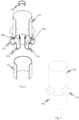
- FIG. 1 it is shown a perspective view with a cut away portion of the side of an embodiment of the invention.
- An arrangement 100 for a sewerage system comprising a French drain according to the present invention comprises an inspection well device 102 suitable to be connected between a French drainage system and another drain system, such as a rainwater drain system, for enabling installation of said French drain at least partly under the another drain.
- the inspection well device 102 comprises a bottom part 104, which is closed preventing unwanted water and dirties, such as rainwater from entering into the French drain, and a tube part 106 protruding from the bottom part 104.
- the top of the tube part 106 is open enabling inspection and purification of the French drain via the tube part 106.
- the size and material of the inspection well device 102 can vary widely.
- the diameter of the inspection well device is preferably e.g. about 100 mm - 600 mm, more preferably e.g. about 250 mm - 280 mm to be compatible for commonly used pipelines.
- the height of the inspection well device is preferably e.g. about 10 mm - 250 mm, more preferably e.g. about 15 mm - 200 mm, but if required, the tube part can be in the same level with the bottom part having no height at all, or the tube part can be as high as required.
- the height as well as the diameter of inspection well device can easily be selected to be what is needed.
- the tube part is selected to protruding so high in a rainwater drain inspection well 112 that rainwater is not able to flow into the French drain.
- the tube part 106 in the embodiment in question, reaches higher level than any outlets 114 for pipelines in the rainwater drain inspection well 112.
- the inspection well device 102 comprises closing means, such as an openable cap 108, for preventing unwanted water, such as rainwater, from entering into the French drain.
- closing means such as an openable cap 108
- the cap 108 as well as the corresponding top of the tube part can be threaded enabling easy opening and closing of the cap 108.
- connection of the cap 108 can also be arranged suitable insulation.
- the height of the tube part 106 is selected so, that when cap 108 is opened, rainwater from the rainwater drain does not flow in, being higher than the middle part of the highest outlet, for example.
- the inspection well device 102 can be connected to a rainwater drain, a rainwater drain inspection well and French drain inspection well.
- the bottom part 104 comprises sleeves 110, which enables the connections of the inspection well device 102.
- the arrangement according to the present invention further comprises a rainwater drain inspection well 112.
- the inspection well device 102 is arranged inside of the rainwater drain inspection well 112, so that the bottom part 104 and the tube part 106 are inside of the rainwater drain inspection well 112.
- the rainwater drain inspection well 112 is arranged to be formed to be continuing from the sleeves 110, or to be connected to the sleeves 110.
- the inspection well device 102 When the inspection well device 102 according to the present invention is connected to a rainwater drain inspection well, the inspection well device 102 is arranged to be at least a partly inside to the rainwater drain inspection well. However, the sleeves 106 can also be arrange outside of the rainwater drain inspection well.
- the rainwater drain inspection well 112 comprises a number of outlets 114 for rainwater pipelines.
- the number of outlets can vary, but preferably the number of the outlets is 1-4. However, more outlets can be formed to the rainwater drain inspection well 112 or the rainwater drain inspection well 112 can be formed without outlets.
- the outlets 114 in the rainwater drain inspection well 112 are arranged in different heights. Preferably, the number of outlets can easily be higher than 4.
- the height of the inspection well device 102 inside of a rainwater drain inspection well 112 is selected so that the inspection well device 102, i.e. the tube part 106, inside the rainwater drain inspection well 112 is higher than the middle point of the a highest outlet.
- the arrangement according to the present invention further comprises a French drain inspection well 116 connectible to a French drain system.
- the French drain inspection well 116 can be connected to the sleeves 110, for example, or arranged to be in connection with the inspection well device 102 by some other means.
Landscapes
- Engineering & Computer Science (AREA)
- Life Sciences & Earth Sciences (AREA)
- General Engineering & Computer Science (AREA)
- Health & Medical Sciences (AREA)
- Hydrology & Water Resources (AREA)
- Public Health (AREA)
- Water Supply & Treatment (AREA)
- Mechanical Engineering (AREA)
- Civil Engineering (AREA)
- Structural Engineering (AREA)
- General Life Sciences & Earth Sciences (AREA)
- Mining & Mineral Resources (AREA)
- Paleontology (AREA)
- Environmental & Geological Engineering (AREA)
- Agronomy & Crop Science (AREA)
- Sewage (AREA)
- Sink And Installation For Waste Water (AREA)
- Medicines Containing Material From Animals Or Micro-Organisms (AREA)
Claims (2)
- Anordnung (100) zum Verbinden eines ersten Abflusssystems, wie etwa eines Regenwasserabflusssystems, und eines Sickerleitungssystems, wobei die Anordnung (100) Folgendes umfasst:eine Inspektionsschachtvorrichtung (102), die geeignet ist, zwischen dem ersten Abflusssystem und dem Sickerleitungssystem angeschlossen zu werden, um in einem installierten Zustand der Anordnung die Installation des Sickerleitungssystems zumindest teilweise unter dem ersten Abflusssystem zu ermöglichen, so dass das erste Abflusssystem und das Sickerleitungssystem getrennte Systeme bleiben,wobei die Anordnung (100) weiter einen an das Sickerleitungssystem anschließbaren Sickerleitungsinspektionsschacht (116) umfasst, wobei die Inspektionsschachtvorrichtung (102) umfasst:ein Bodenteil (104), das Eindringen von unerwünschtem Wasser und Schmutz in die Sickerleitung verhindert,wobei die Anordnung (100) weiter einen Inspektionsschacht (112) und eine Anzahl von Auslässen (114) umfasst, die an dem Inspektionsschacht (112) zum Anschluss an Rohrleitungen des ersten Abflusssystems ausgebildet sind,wobei die Inspektionsschachtvorrichtung (102) weiter ein Rohrteil (106) umfasst, das aus dem Bodenteil (104) herausragt, um in einem installierten Zustand der Anordnung (100) die Sickerleitung zu inspizieren und zu reinigen, wobei die Höhe des Rohrteils (106) so gewählt ist, dass sie höher ist als jeder der Auslässe (114), wobei die Auslässe (114) in unterschiedlichen Höhen angeordnet sind,wobei die Inspektionsschachtvorrichtung (102) in einem Inspektionsschacht (112) angeordnet ist, wobei zumindest das Bodenteil (104) und zumindest das Rohrteil (106) zumindest teilweise in dem Inspektionsschacht (112) angeordnet sind.
- Anordnung (100) nach Anspruch 1, wobei die Inspektionsschachtvorrichtung (102) Verschlussmittel, wie etwa eine zu öffnende Kappe (108), an der Oberseite des Rohrteils (106) umfasst, um zu verhindern, dass unerwünschtes Wasser in die Sickerleitung eindringt.
Priority Applications (1)
| Application Number | Priority Date | Filing Date | Title |
|---|---|---|---|
| HRP20241277TT HRP20241277T1 (hr) | 2016-09-06 | 2017-08-29 | Uređaj za kanalizacijski sustav s francuskim odvodom |
Applications Claiming Priority (2)
| Application Number | Priority Date | Filing Date | Title |
|---|---|---|---|
| FI20165660A FI20165660A7 (fi) | 2016-09-06 | 2016-09-06 | Järjestely salaojan käsittävälle viemärijärjestelmälle |
| PCT/EP2017/071623 WO2018046348A1 (en) | 2016-09-06 | 2017-08-29 | An arrangement for a sewerage system comprising a french drain |
Publications (3)
| Publication Number | Publication Date |
|---|---|
| EP3510207A1 EP3510207A1 (de) | 2019-07-17 |
| EP3510207C0 EP3510207C0 (de) | 2024-08-07 |
| EP3510207B1 true EP3510207B1 (de) | 2024-08-07 |
Family
ID=59791058
Family Applications (1)
| Application Number | Title | Priority Date | Filing Date |
|---|---|---|---|
| EP17761851.9A Active EP3510207B1 (de) | 2016-09-06 | 2017-08-29 | Vorrichtung für drainagevorrichtung umfassend eine französische drainageleitung |
Country Status (13)
| Country | Link |
|---|---|
| US (1) | US20190186118A1 (de) |
| EP (1) | EP3510207B1 (de) |
| JP (1) | JP2019529758A (de) |
| KR (1) | KR20190076949A (de) |
| CN (1) | CN109689986A (de) |
| CA (1) | CA3035851A1 (de) |
| ES (1) | ES2990110T3 (de) |
| FI (1) | FI20165660A7 (de) |
| HR (1) | HRP20241277T1 (de) |
| PL (1) | PL3510207T3 (de) |
| RU (1) | RU2019108415A (de) |
| SG (1) | SG11201901428PA (de) |
| WO (1) | WO2018046348A1 (de) |
Families Citing this family (2)
| Publication number | Priority date | Publication date | Assignee | Title |
|---|---|---|---|---|
| CN114991208B (zh) * | 2022-04-15 | 2023-11-17 | 重庆昂然建筑工程有限公司 | 一种检查井井具安装结构及其施工方法 |
| CN116084533B (zh) * | 2023-04-12 | 2023-06-02 | 河北颛一建筑工程有限公司 | 一种具有泥沙过滤功能的建筑施工用降雨排水结构 |
Family Cites Families (8)
| Publication number | Priority date | Publication date | Assignee | Title |
|---|---|---|---|---|
| GB965831A (en) * | 1962-03-14 | 1964-08-06 | Marley Tile Co Ltd | Improvements in or relating to the venting of drainage systems of buildings |
| FR2480401A1 (fr) * | 1980-04-15 | 1981-10-16 | Syndicat Nal Prof Entre Trav D | Boite de jonction pour installation de drainage agricole ou d'assainissement |
| CN200982030Y (zh) * | 2006-06-12 | 2007-11-28 | 张艳 | 带有管状孔洞的混凝土排水检查井 |
| DE202010001051U1 (de) * | 2010-01-18 | 2010-04-08 | Berding Beton Gmbh | Abwasserschacht, insbesondere Hauskontrollschacht |
| CN202577559U (zh) * | 2012-05-18 | 2012-12-05 | 北京泰宁科创雨水利用技术股份有限公司 | 一种多功能分流井 |
| CN103712020A (zh) * | 2013-11-28 | 2014-04-09 | 江阴海陆高压管件有限公司 | 一种分流管接头 |
| DE202014000333U1 (de) * | 2014-01-20 | 2014-07-11 | Hans Würmseher | Abwasserschacht |
| CN204510449U (zh) * | 2015-03-03 | 2015-07-29 | 常州市科创建筑安装工程有限公司 | 分流截污井 |
-
2016
- 2016-09-06 FI FI20165660A patent/FI20165660A7/fi not_active Application Discontinuation
-
2017
- 2017-08-29 ES ES17761851T patent/ES2990110T3/es active Active
- 2017-08-29 SG SG11201901428PA patent/SG11201901428PA/en unknown
- 2017-08-29 KR KR1020197007418A patent/KR20190076949A/ko not_active Withdrawn
- 2017-08-29 JP JP2019533290A patent/JP2019529758A/ja active Pending
- 2017-08-29 WO PCT/EP2017/071623 patent/WO2018046348A1/en not_active Ceased
- 2017-08-29 HR HRP20241277TT patent/HRP20241277T1/hr unknown
- 2017-08-29 CN CN201780054616.9A patent/CN109689986A/zh active Pending
- 2017-08-29 EP EP17761851.9A patent/EP3510207B1/de active Active
- 2017-08-29 US US16/330,266 patent/US20190186118A1/en not_active Abandoned
- 2017-08-29 RU RU2019108415A patent/RU2019108415A/ru unknown
- 2017-08-29 PL PL17761851.9T patent/PL3510207T3/pl unknown
- 2017-08-29 CA CA3035851A patent/CA3035851A1/en not_active Abandoned
Also Published As
| Publication number | Publication date |
|---|---|
| HRP20241277T1 (hr) | 2024-12-06 |
| SG11201901428PA (en) | 2019-03-28 |
| EP3510207C0 (de) | 2024-08-07 |
| FI20165660A (fi) | 2018-03-07 |
| CA3035851A1 (en) | 2018-03-15 |
| WO2018046348A1 (en) | 2018-03-15 |
| ES2990110T3 (es) | 2024-11-28 |
| EP3510207A1 (de) | 2019-07-17 |
| KR20190076949A (ko) | 2019-07-02 |
| RU2019108415A3 (de) | 2021-04-12 |
| FI20165660A7 (fi) | 2018-03-07 |
| JP2019529758A (ja) | 2019-10-17 |
| RU2019108415A (ru) | 2020-10-08 |
| PL3510207T3 (pl) | 2025-01-13 |
| CN109689986A (zh) | 2019-04-26 |
| US20190186118A1 (en) | 2019-06-20 |
Similar Documents
| Publication | Publication Date | Title |
|---|---|---|
| AU2010273166B2 (en) | Liquid run-off disposal system | |
| EP3510207B1 (de) | Vorrichtung für drainagevorrichtung umfassend eine französische drainageleitung | |
| JP2013253444A (ja) | 多層式下水道管 | |
| KR100982819B1 (ko) | 조립식 배수로 | |
| JP2011074563A (ja) | 雨水浸透システム | |
| CN107386320B (zh) | 穿越地下混凝土水管道的地下管廊的施工方法 | |
| KR20120007819U (ko) | 이물질 배출 기능이 구비된 배수 홈통 | |
| JP2011080332A (ja) | 排水構造 | |
| KR100711607B1 (ko) | 건축지붕 누수방지 시설구조 | |
| JP2014190098A (ja) | 雨水貯溜配管構造とそれに用いる堰部材 | |
| HK40007314A (en) | An arrangement for a sewerage system comprising a french drain | |
| KR101653722B1 (ko) | 조립식 원심력 배수로관 및 이를 이용한 시공방법 | |
| KR100706161B1 (ko) | 합류식 하수관거 설치구조 | |
| JP2011219996A (ja) | 地盤沈下対策配管構造及び地盤沈下対策配管方法 | |
| JP2010138642A (ja) | 井戸及び井戸の構築方法 | |
| JP6391008B2 (ja) | 雨水貯溜管路構造とそれに用いる雨水桝 | |
| JP6832754B2 (ja) | 地下灌漑システム | |
| KR100667583B1 (ko) | 분류식 하수관거 설치구조 | |
| KR200430582Y1 (ko) | 관을 이용한 빗물 저류조 구조 | |
| KR101569048B1 (ko) | 자동 배수 기능을 갖는 제수변 보호통 | |
| KR20110139901A (ko) | 밸브실 구조물의 집수정 설치구조 | |
| CN201574435U (zh) | 使用了管状的贮留槽的雨水贮留装置 | |
| AU2009101039A4 (en) | Installation of a tank in the ground | |
| CN210658607U (zh) | 一种地下排水管道预埋防护结构 | |
| KR100951457B1 (ko) | 지중 저압 접속함의 자동배수장치 |
Legal Events
| Date | Code | Title | Description |
|---|---|---|---|
| REG | Reference to a national code |
Ref country code: HR Ref legal event code: TUEP Ref document number: P20241277T Country of ref document: HR |
|
| STAA | Information on the status of an ep patent application or granted ep patent |
Free format text: STATUS: UNKNOWN |
|
| STAA | Information on the status of an ep patent application or granted ep patent |
Free format text: STATUS: THE INTERNATIONAL PUBLICATION HAS BEEN MADE |
|
| PUAI | Public reference made under article 153(3) epc to a published international application that has entered the european phase |
Free format text: ORIGINAL CODE: 0009012 |
|
| STAA | Information on the status of an ep patent application or granted ep patent |
Free format text: STATUS: REQUEST FOR EXAMINATION WAS MADE |
|
| 17P | Request for examination filed |
Effective date: 20190404 |
|
| AK | Designated contracting states |
Kind code of ref document: A1 Designated state(s): AL AT BE BG CH CY CZ DE DK EE ES FI FR GB GR HR HU IE IS IT LI LT LU LV MC MK MT NL NO PL PT RO RS SE SI SK SM TR |
|
| AX | Request for extension of the european patent |
Extension state: BA ME |
|
| DAV | Request for validation of the european patent (deleted) | ||
| DAX | Request for extension of the european patent (deleted) | ||
| STAA | Information on the status of an ep patent application or granted ep patent |
Free format text: STATUS: EXAMINATION IS IN PROGRESS |
|
| 17Q | First examination report despatched |
Effective date: 20220325 |
|
| RAP3 | Party data changed (applicant data changed or rights of an application transferred) |
Owner name: HYBRID SYSTEM OUE |
|
| GRAP | Despatch of communication of intention to grant a patent |
Free format text: ORIGINAL CODE: EPIDOSNIGR1 |
|
| STAA | Information on the status of an ep patent application or granted ep patent |
Free format text: STATUS: GRANT OF PATENT IS INTENDED |
|
| INTG | Intention to grant announced |
Effective date: 20240307 |
|
| GRAS | Grant fee paid |
Free format text: ORIGINAL CODE: EPIDOSNIGR3 |
|
| GRAA | (expected) grant |
Free format text: ORIGINAL CODE: 0009210 |
|
| STAA | Information on the status of an ep patent application or granted ep patent |
Free format text: STATUS: THE PATENT HAS BEEN GRANTED |
|
| AK | Designated contracting states |
Kind code of ref document: B1 Designated state(s): AL AT BE BG CH CY CZ DE DK EE ES FI FR GB GR HR HU IE IS IT LI LT LU LV MC MK MT NL NO PL PT RO RS SE SI SK SM TR |
|
| REG | Reference to a national code |
Ref country code: GB Ref legal event code: FG4D |
|
| REG | Reference to a national code |
Ref country code: CH Ref legal event code: EP |
|
| REG | Reference to a national code |
Ref country code: DE Ref legal event code: R096 Ref document number: 602017083903 Country of ref document: DE |
|
| REG | Reference to a national code |
Ref country code: IE Ref legal event code: FG4D |
|
| U01 | Request for unitary effect filed |
Effective date: 20240829 |
|
| U07 | Unitary effect registered |
Designated state(s): AT BE BG DE DK EE FI FR IT LT LU LV MT NL PT RO SE SI Effective date: 20240910 |
|
| U20 | Renewal fee for the european patent with unitary effect paid |
Year of fee payment: 8 Effective date: 20240910 |
|
| REG | Reference to a national code |
Ref country code: HR Ref legal event code: ODRP Ref document number: P20241277T Country of ref document: HR Payment date: 20240924 Year of fee payment: 8 |
|
| REG | Reference to a national code |
Ref country code: ES Ref legal event code: FG2A Ref document number: 2990110 Country of ref document: ES Kind code of ref document: T3 Effective date: 20241128 |
|
| REG | Reference to a national code |
Ref country code: HR Ref legal event code: T1PR Ref document number: P20241277 Country of ref document: HR |
|
| PG25 | Lapsed in a contracting state [announced via postgrant information from national office to epo] |
Ref country code: GR Free format text: LAPSE BECAUSE OF FAILURE TO SUBMIT A TRANSLATION OF THE DESCRIPTION OR TO PAY THE FEE WITHIN THE PRESCRIBED TIME-LIMIT Effective date: 20241108 |
|
| PG25 | Lapsed in a contracting state [announced via postgrant information from national office to epo] |
Ref country code: IS Free format text: LAPSE BECAUSE OF FAILURE TO SUBMIT A TRANSLATION OF THE DESCRIPTION OR TO PAY THE FEE WITHIN THE PRESCRIBED TIME-LIMIT Effective date: 20241207 |
|
| PG25 | Lapsed in a contracting state [announced via postgrant information from national office to epo] |
Ref country code: RS Free format text: LAPSE BECAUSE OF FAILURE TO SUBMIT A TRANSLATION OF THE DESCRIPTION OR TO PAY THE FEE WITHIN THE PRESCRIBED TIME-LIMIT Effective date: 20241107 |
|
| PG25 | Lapsed in a contracting state [announced via postgrant information from national office to epo] |
Ref country code: RS Free format text: LAPSE BECAUSE OF FAILURE TO SUBMIT A TRANSLATION OF THE DESCRIPTION OR TO PAY THE FEE WITHIN THE PRESCRIBED TIME-LIMIT Effective date: 20241107 Ref country code: IS Free format text: LAPSE BECAUSE OF FAILURE TO SUBMIT A TRANSLATION OF THE DESCRIPTION OR TO PAY THE FEE WITHIN THE PRESCRIBED TIME-LIMIT Effective date: 20241207 Ref country code: GR Free format text: LAPSE BECAUSE OF FAILURE TO SUBMIT A TRANSLATION OF THE DESCRIPTION OR TO PAY THE FEE WITHIN THE PRESCRIBED TIME-LIMIT Effective date: 20241108 |
|
| REG | Reference to a national code |
Ref country code: CH Ref legal event code: PL |
|
| PG25 | Lapsed in a contracting state [announced via postgrant information from national office to epo] |
Ref country code: SM Free format text: LAPSE BECAUSE OF FAILURE TO SUBMIT A TRANSLATION OF THE DESCRIPTION OR TO PAY THE FEE WITHIN THE PRESCRIBED TIME-LIMIT Effective date: 20240807 |
|
| PG25 | Lapsed in a contracting state [announced via postgrant information from national office to epo] |
Ref country code: CH Free format text: LAPSE BECAUSE OF NON-PAYMENT OF DUE FEES Effective date: 20240831 |
|
| PG25 | Lapsed in a contracting state [announced via postgrant information from national office to epo] |
Ref country code: CZ Free format text: LAPSE BECAUSE OF FAILURE TO SUBMIT A TRANSLATION OF THE DESCRIPTION OR TO PAY THE FEE WITHIN THE PRESCRIBED TIME-LIMIT Effective date: 20240807 |
|
| PG25 | Lapsed in a contracting state [announced via postgrant information from national office to epo] |
Ref country code: SK Free format text: LAPSE BECAUSE OF FAILURE TO SUBMIT A TRANSLATION OF THE DESCRIPTION OR TO PAY THE FEE WITHIN THE PRESCRIBED TIME-LIMIT Effective date: 20240807 |
|
| PLBE | No opposition filed within time limit |
Free format text: ORIGINAL CODE: 0009261 |
|
| STAA | Information on the status of an ep patent application or granted ep patent |
Free format text: STATUS: NO OPPOSITION FILED WITHIN TIME LIMIT |
|
| PG25 | Lapsed in a contracting state [announced via postgrant information from national office to epo] |
Ref country code: MC Free format text: LAPSE BECAUSE OF FAILURE TO SUBMIT A TRANSLATION OF THE DESCRIPTION OR TO PAY THE FEE WITHIN THE PRESCRIBED TIME-LIMIT Effective date: 20240807 |
|
| 26N | No opposition filed |
Effective date: 20250508 |
|
| PG25 | Lapsed in a contracting state [announced via postgrant information from national office to epo] |
Ref country code: IE Free format text: LAPSE BECAUSE OF NON-PAYMENT OF DUE FEES Effective date: 20240829 |
|
| REG | Reference to a national code |
Ref country code: HR Ref legal event code: ODRP Ref document number: P20241277 Country of ref document: HR Payment date: 20250902 Year of fee payment: 9 |
|
| U20 | Renewal fee for the european patent with unitary effect paid |
Year of fee payment: 9 Effective date: 20250829 |
|
| PGFP | Annual fee paid to national office [announced via postgrant information from national office to epo] |
Ref country code: ES Payment date: 20250916 Year of fee payment: 9 |
|
| PGFP | Annual fee paid to national office [announced via postgrant information from national office to epo] |
Ref country code: NO Payment date: 20250902 Year of fee payment: 9 |
|
| PGFP | Annual fee paid to national office [announced via postgrant information from national office to epo] |
Ref country code: PL Payment date: 20250903 Year of fee payment: 9 |
|
| PGFP | Annual fee paid to national office [announced via postgrant information from national office to epo] |
Ref country code: GB Payment date: 20250901 Year of fee payment: 9 |
|
| PGFP | Annual fee paid to national office [announced via postgrant information from national office to epo] |
Ref country code: HR Payment date: 20250902 Year of fee payment: 9 |
|
| PG25 | Lapsed in a contracting state [announced via postgrant information from national office to epo] |
Ref country code: CY Free format text: LAPSE BECAUSE OF FAILURE TO SUBMIT A TRANSLATION OF THE DESCRIPTION OR TO PAY THE FEE WITHIN THE PRESCRIBED TIME-LIMIT; INVALID AB INITIO Effective date: 20170829 |
|
| PG25 | Lapsed in a contracting state [announced via postgrant information from national office to epo] |
Ref country code: HU Free format text: LAPSE BECAUSE OF FAILURE TO SUBMIT A TRANSLATION OF THE DESCRIPTION OR TO PAY THE FEE WITHIN THE PRESCRIBED TIME-LIMIT; INVALID AB INITIO Effective date: 20170829 |