EP3509783B1 - Cutting tool having a coolant chamber with an integrally formed coolant deflection portion and tool body - Google Patents
Cutting tool having a coolant chamber with an integrally formed coolant deflection portion and tool body Download PDFInfo
- Publication number
- EP3509783B1 EP3509783B1 EP17765264.1A EP17765264A EP3509783B1 EP 3509783 B1 EP3509783 B1 EP 3509783B1 EP 17765264 A EP17765264 A EP 17765264A EP 3509783 B1 EP3509783 B1 EP 3509783B1
- Authority
- EP
- European Patent Office
- Prior art keywords
- chamber
- coolant
- tool
- cutting
- cutting tool
- Prior art date
- Legal status (The legal status is an assumption and is not a legal conclusion. Google has not performed a legal analysis and makes no representation as to the accuracy of the status listed.)
- Active
Links
Images


Classifications
-
- B—PERFORMING OPERATIONS; TRANSPORTING
- B23—MACHINE TOOLS; METAL-WORKING NOT OTHERWISE PROVIDED FOR
- B23B—TURNING; BORING
- B23B27/00—Tools for turning or boring machines; Tools of a similar kind in general; Accessories therefor
- B23B27/10—Cutting tools with special provision for cooling
-
- B—PERFORMING OPERATIONS; TRANSPORTING
- B23—MACHINE TOOLS; METAL-WORKING NOT OTHERWISE PROVIDED FOR
- B23C—MILLING
- B23C5/00—Milling-cutters
- B23C5/02—Milling-cutters characterised by the shape of the cutter
- B23C5/10—Shank-type cutters, i.e. with an integral shaft
- B23C5/109—Shank-type cutters, i.e. with an integral shaft with removable cutting inserts
-
- B—PERFORMING OPERATIONS; TRANSPORTING
- B23—MACHINE TOOLS; METAL-WORKING NOT OTHERWISE PROVIDED FOR
- B23C—MILLING
- B23C5/00—Milling-cutters
- B23C5/28—Features relating to lubricating or cooling
- B23C5/283—Cutting inserts with internal coolant channels
-
- B—PERFORMING OPERATIONS; TRANSPORTING
- B23—MACHINE TOOLS; METAL-WORKING NOT OTHERWISE PROVIDED FOR
- B23C—MILLING
- B23C5/00—Milling-cutters
- B23C5/28—Features relating to lubricating or cooling
- B23C5/286—Deflectors
-
- B—PERFORMING OPERATIONS; TRANSPORTING
- B23—MACHINE TOOLS; METAL-WORKING NOT OTHERWISE PROVIDED FOR
- B23B—TURNING; BORING
- B23B2205/00—Fixation of cutting inserts in holders
- B23B2205/04—Fixation screws, bolts or pins of particular form
-
- B—PERFORMING OPERATIONS; TRANSPORTING
- B23—MACHINE TOOLS; METAL-WORKING NOT OTHERWISE PROVIDED FOR
- B23B—TURNING; BORING
- B23B2250/00—Compensating adverse effects during turning, boring or drilling
- B23B2250/12—Cooling and lubrication
- B23B2250/121—Insert with coolant channels
-
- B—PERFORMING OPERATIONS; TRANSPORTING
- B23—MACHINE TOOLS; METAL-WORKING NOT OTHERWISE PROVIDED FOR
- B23B—TURNING; BORING
- B23B2250/00—Compensating adverse effects during turning, boring or drilling
- B23B2250/12—Cooling and lubrication
- B23B2250/122—Internal coolant reservoir
-
- B—PERFORMING OPERATIONS; TRANSPORTING
- B23—MACHINE TOOLS; METAL-WORKING NOT OTHERWISE PROVIDED FOR
- B23C—MILLING
- B23C2210/00—Details of milling cutters
- B23C2210/16—Fixation of inserts or cutting bits in the tool
- B23C2210/165—Fixation bolts
-
- B—PERFORMING OPERATIONS; TRANSPORTING
- B23—MACHINE TOOLS; METAL-WORKING NOT OTHERWISE PROVIDED FOR
- B23C—MILLING
- B23C2250/00—Compensating adverse effects during milling
- B23C2250/12—Cooling and lubrication
Definitions
- the present invention relates to tool bodies and to cutting tools of the type in which a cutting insert is releasably retained in an insert pocket of a tool body. More particularly, this application relates to such cutting tools having a cooling mechanism.
- Cutting tools having a cutting insert releasably retained in an insert pocket of a tool body can be provided with a cooling mechanism.
- the cooling mechanism can be provided by one or more coolant ducts, having coolant outlets, for conveying coolant fluid to a cutting portion of cutting insert.
- An example of such a cutting tool is disclosed in, for example, US 9,289,836 B2 , where the coolant outlet is located rotationally forward of the cutting insert.
- Another example is CH 708 238 A2 , which discloses a tool body according to the preamble of claim 1, where the coolant outlet is formed with a separate distributing element.
- the tool bodies of such cutting tools are made from steel and are manufactured by traditional methods such as, for example, turning, milling and drilling.
- the coolant ducts are created during a post manufacturing process by drilling a hole from the outside of the tool body.
- the tool body can be manufactured by newer techniques, such as Additive Manufacturing.
- Additive Manufacturing refers to a class of manufacturing processes, in which a part is built by adding layers of material upon one another. This allows, in the case of tool bodies, the coolant ducts to be created at the same time the tool body is manufactured. This permits the coolant ducts to have an unusual structure (e.g. a non-circular cross-section) that is not limited as in the older techniques mentioned above. It also allows the coolant ducts to be curved.
- An example of such a cutting tool is disclosed in, for example, US 8,946,585 B2 .
- the coolant deflection portion can completely overhang the outlet orifice.
- the coolant chamber can be recessed in the tool body surface so that the coolant deflection portion does not protrude from the tool body surface.
- the outlet orifice can be generally circular.
- the chamber deflection surface and the chamber orifice surface can be planar.
- the two chamber minor surfaces can be are concavely curved.
- the outlet orifice can define an outlet orifice plane.
- the outlet orifice can have an outlet orifice axis which is perpendicular to the outlet orifice plane.
- the chamber deflection surface can form a chamber deflection angle with the outlet orifice axis.
- the chamber deflection angle can be in the range 90° ⁇ ⁇ ⁇ 130°.
- the chamber orifice surface can be parallel to the outlet orifice plane.
- the coolant chamber can extend along a chamber central axis that passes between the chamber deflection surface, the chamber orifice surface and the chamber minor surfaces. As measured in a cross-sectional plane perpendicular to the chamber central axis, the coolant chamber can have an increasing cross-section, in a direction towards the coolant chamber opening.
- the coolant chamber can extend along a chamber central axis.
- the chamber deflection surface and the chamber orifice surface can be longer than the two chamber minor surfaces.
- the cutting insert can comprise a cutting edge.
- the coolant chamber opening has an elongated shape that can extend longitudinally generally in the same direction as the cutting edge.
- the length of coolant chamber opening can be at least 50% the length of the cutting edge.
- the tool body can comprise exactly two coolant ducts.
- the insert pocket can comprise a pocket base surface and a threaded bore opening out thereto.
- the two coolant ducts can extend on either side of the threaded bore.
- the cutting tool can be configured to rotate in a direction of rotation around the central tool axis.
- the tool body can comprise a forward facing body face surface and a body periphery surface, the body periphery surface extending circumferentially along the central tool axis and forming a boundary of the body face surface at a forward end of the cutting tool.
- the coolant chamber opening can be located rotationally behind the insert pocket.
- the coolant chamber opening and the insert pocket can be aligned in the circumferential direction of the cutting tool.
- the cutting tool can be configured to rotate in a direction of rotation around the central tool axis.
- the tool body can comprise a forward facing body face surface and a body periphery surface, the body periphery surface extending circumferentially along the central tool axis and forming a boundary of the body face surface at a forward end of the cutting tool.
- the insert pocket can open out to the body face surface.
- the coolant chamber opening can be angularly aligned with the insert pocket about the central tool axis.
- the cutting tool can be a rotary milling cutter.
- the tool body can comprise a forward facing body face surface and a body periphery surface, the body periphery surface extending circumferentially along the central tool axis and forming a boundary of the body face surface at a forward end of the cutting tool.
- the insert pocket can open out to the body face surface.
- the coolant chamber opening can be located underneath the insert pocket.
- the cutting tool can be a turning tool not configured to rotate around the central tool axis.
- the cutting insert can have a cutting edge which extends along the tool central axis in the forward-to-rearward direction.
- the coolant chamber opening can extend longitudinally generally in the same direction as the cutting edge.
- the coolant chamber opening can be positioned, relative to the insert pocket, so as to direct a coolant over and along a relief surface associated with the cutting edge such that the coolant impacts a juncture between the cutting edge and a workpiece being cut by the cutting tool.
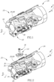
- Figs. 1 and 2 showing a cutting tool 20, for chip removal, in accordance with embodiments of the subject matter of the present application.
- the cutting tool 20 has a cutting insert 22 which can be typically made from cemented carbide.
- the cutting tool 20 also has a tool body 24 which can be typically made from steel and is manufactured by an Additive Manufacturing process.
- the Additive Manufacturing process used is Direct Metal Laser Sintering. However, other Additive Manufacturing techniques can be used.
- the cutting tool 20 is a rotary milling cutter. It is noted, however, that the subject matter of the present application also applies to other types of cutting tools, for example, but not limited to, turning tools.
- the cutting tool 20 is adjustable between a released and fastened position. In the fastened position of the cutting tool 20 , the cutting insert 22 is releasably attached to the tool body 24.
- the tool body 24 includes a tool body surface 26.
- the tool body 24 includes an insert pocket 28, for retaining (i.e. seating) a cutting insert 22 therein.
- the insert pocket 28 is recessed in the tool body surface 26. It is understood that the term "recessed" when used in respect to an element related to the tool body 24 refers to a structure that is created during the additive manufacturing of the tool body 24, and not in a post manufacturing machining process.
- the insert pocket 28 can include a pocket base surface 30 and a pocket side surface 32 oriented transversely thereto.
- the insert pocket 28 can include a threaded bore 34 that opens out to the pocket base surface 30 .
- the threaded bore 34 is for threadingly engaging a retaining screw 36 as described in the description hereinafter.
- the cutting insert 22 has a cutting edge 38 formed at the intersection of a rake surface 40 and a relief surface 42.
- Fig. 3 showing a detail of Fig. 1 , where the cutting insert 22 is releasably retained in an insert pocket 28 of the tool body 24.
- the retaining screw 36 is used to clamp the cutting insert 22 in the insert pocket 28 of the tool body 24 through a through bore.
- other clamping methods may be used. It is noted that the cutting insert 22 and the seating thereof in the insert pocket 28 is known in the field of metal cutting and is not part of the invention.
- the tool body 24 includes a coolant chamber 44 that opens out to the tool body surface 26 at a coolant chamber opening 46.
- the coolant chamber 44 can be closed at the end opposite the coolant chamber opening 46 by a chamber end surface 48.
- the coolant chamber is designed to direct coolant fluid towards the cutting edge 38 of the cutting insert 22 with which it is associated.
- the coolant fluid can be, for example a liquid, such as oilbased or chemical coolants or a gas, such as air.
- the coolant chamber 44 can extend along a chamber central axis C.
- the chamber central axis C can pass between the chamber deflection surface 50 , the chamber orifice surface 52 and the chamber minor surfaces 54.
- the chamber central axis C can pass through the coolant chamber opening 46 and intersect the chamber end surface 48.
- the coolant chamber opening 46 can have an edge that extends smoothly, i.e. with no jagged portions, around its periphery.
- the coolant chamber opening 46 can have a generally rectangular shape.
- the coolant chamber opening 46 is spaced apart from the insert pocket 28 by an opening distance D.
- the value of the opening distance D can vary along the length coolant chamber opening 46.
- the optimal value of the opening distance D is determined by several factors. One such factor is the desire for the coolant fluid to avoid the base of the cutting insert 22 (which may protrude from the insert pocket 28) when it exits from the coolant chamber opening 46.
- the opening distance D is ideally less than 5mm.
- the coolant chamber opening 46 has an elongated shape.
- the coolant chamber opening 46 can extend longitudinally generally in the same direction as the cutting edge 38.
- the coolant chamber opening 46 is oriented approximately at a 5° angle with respect to the cutting edge 38, so that the opening distance D decreases uniformly.
- the length of coolant chamber opening 46 can be at least 50% the length of the cutting edge 38.
- this allows at least a majority of the length of the cutting edge 38 to receive coolant fluid.
- the coolant chamber opening 46 Due to its elongated, non-circular shape, the coolant chamber opening 46 is configured to supply a stream of coolant having a non-circular cross-section.
- the coolant chamber 44 can be formed peripherally by a chamber deflection surface 50 and a chamber orifice surface 52 that oppose each other and two opposing chamber minor surfaces 54.
- the two opposing chamber minor surfaces 54 can each connect the chamber deflection surface 50 and the chamber orifice surface 52.
- the chamber deflection surface 50 and the chamber orifice surface 52 can be planar.
- the chamber minor surfaces 54 can be concavely curved. In a cross sectional plane perpendicular to the chamber central axis C, the chamber deflection surface 50 and the chamber orifice surface 52 can be longer than the two chamber minor surfaces 54.
- the chamber orifice surface 52 includes an outlet orifice 56 whose purpose is described in detail later in the description.
- the chamber deflection surface 50 is located on a coolant deflection portion 58, which is integrally formed with the tool body 24. That is to say, the coolant deflection portion 58 is connected to the tool body surface 26 and has unitary one-piece construction therewith.
- the coolant chamber 44 is bounded on a side opposite the outlet orifice 56 by the coolant deflection portion 58.
- the coolant chamber 44 can be recessed in the tool body surface 26 so that the coolant deflection portion 58 does not protrude from the tool body surface 26.
- the coolant deflection portion 58, or more specifically, the chamber deflection surface 50 serves to deflect the coolant fluid, after exiting the outlet orifice 56 under pressure, towards the cutting edge 38 of the cutting insert 22.
- the coolant chamber opening 46 is configured to eject a jet of coolant having a non-circular cross-section. Furthermore, the elongated, non-circular shape of the coolant chamber opening 46 and the chamber deflection surface 50 , together are configured to direct a coolant over and along a relief surface associated with the cutting edge 38 such that the coolant impacts a juncture between the cutting edge 38 and a workpiece being cut by the cutting tool 20 . This results in emitting an elongated sheet of coolant through the coolant chamber opening 46, such that the coolant travels over and along a relief surface of the cutting insert 22 and impacts at a juncture between a cutting edge 38 of the insert and a workpiece.
- the tool body 24 includes at least one coolant duct 60a , 60b .
- the at least one coolant duct 60a , 60b acts for conveying coolant fluid to the cutting insert 22 via the coolant chamber 44.
- the tool body 24 can include exactly two coolant ducts, a first and second coolant duct 60a , 60b .
- this increases the amount of coolant fluid entering the coolant chamber 44.
- the two coolant ducts 60a , 60b can extend on either side of the threaded bore 34. It is understood that the coolant deflection portion 58 is located completely outside of the at least one coolant duct 60a, 60b.
- the coolant duct 60a extends between an inlet orifice 62a and the outlet orifice 56.
- the inlet orifice 62a is in fluid communication with a coolant source that supplies coolant fluid (not shown).
- the cooling fluid enters the coolant duct 60a at the inlet orifice 62a, flows along the coolant duct 60a and exits at the outlet orifice 56.
- the coolant duct 60a is in fluid communication with a central coolant duct 64 and the inlet orifice 62a is located at the central coolant duct 64.
- the second coolant duct 60b is in fluid communication with the central coolant duct 64 at a second inlet orifice 62b located at the central coolant duct 64.
- the coolant duct 60a opens out (terminates) in the coolant chamber 44, forming the outlet orifice 56. Stated differently, the coolant duct 60a intersects the coolant chamber 44 to form the outlet orifice 56.
- the coolant duct 60a has a cross-section that can increase in size as it approaches the coolant chamber 44.
- the outlet orifice 56 can be generally circular.
- the outlet orifice 56 can be located on the chamber orifice surface 52.
- the outlet orifice 56 defines an outlet orifice plane P. All points on the outlet orifice 56 can be contained in the outlet orifice plane P.
- the outlet orifice 56 has an outlet orifice axis O which is perpendicular to the outlet orifice plane P.
- the coolant deflection portion 58 at least partially overhangs the outlet orifice 56 in a direction towards the insert pocket 28. Specifically, in a front view of the coolant chamber 44, the outlet orifice 56 is at least partially hidden by the coolant deflection portion 58.
- a front view of the coolant chamber 44 is defined as one taken in front of the coolant chamber 44 in a direction along the outlet orifice axis O.
- the coolant deflection portion 58 can completely overhang the outlet orifice 56.
- the outlet orifice axis O can intersect the coolant deflection portion 58.
- the chamber deflection surface 50 can form an external chamber deflection angle ⁇ with the outlet orifice axis O.
- the chamber deflection angle ⁇ can be in the range 90° ⁇ ⁇ ⁇ 130°.
- the chamber orifice surface 52 can be parallel to the outlet orifice plane P (i.e. form a 90° angle with the outlet orifice axis O).
- the chamber deflection surface 50 and the chamber orifice surface 52 can taper away each other in a direction towards the coolant chamber opening 46.
- the two chamber minor surfaces 54 can also taper away from each other in a direction towards the coolant chamber opening 46.
- the coolant chamber 44 can have an increasing cross-section, in a direction towards the coolant chamber opening 46.
- the said tapering is intended so that the coolant fluid also has an increasing cross-section as it exits and increases in distance away from the coolant chamber opening 46.
- the chamber central axis C can form a chamber axis angle ⁇ with the outlet orifice axis O.
- the chamber axis angle ⁇ can be in the range 90° ⁇ ⁇ ⁇ 110°.
- the chamber orifice surface 52 can form an obtuse internal angle with the tool body surface 26.
- the chamber deflection surface 50 can form an acute internal angle with the tool body surface 26.
- the cutting tool 20 has a central tool axis A around which the cutting tool 20 rotates in a direction of rotation R.
- the central tool axis A extends in a forward D F to rearward direction D R .
- the tool body 24 includes a forward facing body face surface 66 and a body periphery surface 68.
- the body periphery surface 68 extends circumferentially along the central tool axis A and forms a boundary of the body face surface 66 at a forward end of the cutting tool 20 .
- the central tool axis A can intersect the body face surface 66.
- the cutting tool 20 can include one or more axial rows of insert pockets 28, seating cutting inserts 22, where each cutting insert 22 has an associated at least one coolant chamber 44.
- the body periphery surface 68 constitutes the tool body surface 26.
- the cutting edge 38 is the cutting edge furthest from the central tool axis A.
- the coolant chamber opening 46 can be located rotationally behind the insert pocket 28. Moreover, the coolant chamber opening 46 and the insert pocket 28 can be aligned in the circumferential direction of the cutting tool 20 .
- the body face surface 66 constitutes the tool body surface 26.
- the insert pocket 28 can open out to body face surface 66 at a forward end of the cutting tool 20 .
- the cutting edge 38 is the axially forwardmost cutting edge.
- the coolant chamber opening 46 is angularly aligned with the insert pocket 28 about the central tool axis A.
- the coolant fluid reaches the cutting edge 38 in a direction from the relief surface 42 as opposed to traditionally the rake surface 40 (as shown in US 9,289,836 ).
- this means the coolant fluid is not obstructed by metal chips produced by the metal cutting operation.
- the cutting inserts 22 seated in insert pockets 28 in an axial forwardmost row of insert pockets 28 can be associated with coolant chambers 44 in accordance with both embodiments.
- the cutting tool 20 has a central tool axis A, about which the cutting tool 20 is not configured to rotate.
- the central tool axis A extends in a forward D F to rearward direction D R .
- the tool body 24 includes a forward facing body face surface 66 and a body periphery surface 68.
- the body periphery surface 68 extends circumferentially along the central tool axis A and forms a boundary of the body face surface 66 at a forward end of the cutting tool 20.
- the central tool axis A can intersect the body face surface 66.
- the body face surface 66 constitutes the tool body surface 26.
- the insert pocket 28 can open out to body face surface 66 at a forward end of the cutting tool 20 .
- the cutting edge 38 is the axially forwardmost cutting edge.
- the coolant chamber opening 46 is located underneath the insert pocket 28.
- coolant deflection portion 58 is integrally formed with the too body 24 in a unitary one-piece construction there is no need to assemble the tool body 24 after manufacture.
- the coolant fluid as it leaves the coolant chamber 44, takes the form of the coolant chamber opening 46.
- a large volume of coolant fluid can be conveyed towards the cutting insert 22.
Landscapes
- Engineering & Computer Science (AREA)
- Mechanical Engineering (AREA)
- Cutting Tools, Boring Holders, And Turrets (AREA)
- Milling Processes (AREA)
Applications Claiming Priority (2)
| Application Number | Priority Date | Filing Date | Title |
|---|---|---|---|
| US201662384350P | 2016-09-07 | 2016-09-07 | |
| PCT/IL2017/050955 WO2018047158A1 (en) | 2016-09-07 | 2017-08-28 | Cutting tool having a coolant chamber with an integrally formed coolant deflection portion and tool body |
Publications (2)
| Publication Number | Publication Date |
|---|---|
| EP3509783A1 EP3509783A1 (en) | 2019-07-17 |
| EP3509783B1 true EP3509783B1 (en) | 2024-09-11 |
Family
ID=59856564
Family Applications (1)
| Application Number | Title | Priority Date | Filing Date |
|---|---|---|---|
| EP17765264.1A Active EP3509783B1 (en) | 2016-09-07 | 2017-08-28 | Cutting tool having a coolant chamber with an integrally formed coolant deflection portion and tool body |
Country Status (7)
| Country | Link |
|---|---|
| US (1) | US10201862B2 (https=) |
| EP (1) | EP3509783B1 (https=) |
| JP (1) | JP7053568B2 (https=) |
| KR (1) | KR102307031B1 (https=) |
| CN (1) | CN109661288B (https=) |
| TW (1) | TW201811471A (https=) |
| WO (1) | WO2018047158A1 (https=) |
Families Citing this family (14)
| Publication number | Priority date | Publication date | Assignee | Title |
|---|---|---|---|---|
| DE112017004162B4 (de) * | 2016-08-22 | 2024-11-14 | Kyocera Corporation | Schneidwerkzeughalter, Schneidwerkzeug und Verfahren des Herstellens eines maschinell-bearbeiteten Produkts unter Verwendung derselben |
| DE102017122054A1 (de) | 2017-09-22 | 2019-03-28 | Kennametal Inc. | Schneidwerkzeug sowie Verfahren zur Herstellung eines Schneidwerkzeugs |
| CN112703076B (zh) * | 2018-09-12 | 2023-06-06 | 住友电工硬质合金株式会社 | 切削工具 |
| US10814406B1 (en) | 2019-04-24 | 2020-10-27 | Raytheon Technologies Corporation | Internal cooling passages for rotating cutting tools |
| DE102019127027A1 (de) | 2019-10-08 | 2021-04-08 | Kennametal Inc. | Schneidwerkzeug |
| DE112020006749T5 (de) * | 2020-02-18 | 2022-12-15 | Sumitomo Electric Industries, Ltd. | Werkzeughauptkörper und Verfahren zur Herstellung eines Werkzeughauptkörpers |
| US11318541B2 (en) * | 2020-06-30 | 2022-05-03 | Iscar, Ltd. | Light-weight tool holder with coolant cavity having varying cross-sectional area and cutting tool |
| USD1009108S1 (en) | 2020-09-21 | 2023-12-26 | Kyocera Unimerco Tooling A/S | Drill |
| EP4094868A1 (en) | 2021-05-26 | 2022-11-30 | AB Sandvik Coromant | Flank cooling for a milling tool |
| US12533737B2 (en) * | 2021-09-03 | 2026-01-27 | Makino Inc. | Method for manufacturing a rotatable tool body to minimize cutting insert runout, a tool body produced therefrom, and a method of using such a tool body |
| DE102022101647A1 (de) * | 2022-01-25 | 2023-07-27 | KSB SE & Co. KGaA | Rotierendes Trägerwerkzeug |
| DE102022101646A1 (de) * | 2022-01-25 | 2023-07-27 | KSB SE & Co. KGaA | Kühlkanäle Hybridwerkzeug |
| DE102022126883A1 (de) * | 2022-10-14 | 2024-04-25 | Gühring KG | Zerspanungswerkzeug |
| CN118180468B (zh) * | 2024-04-30 | 2024-12-06 | 宁波旭升集团股份有限公司 | 一种旋转刀具 |
Citations (1)
| Publication number | Priority date | Publication date | Assignee | Title |
|---|---|---|---|---|
| WO2014207747A2 (en) * | 2013-06-27 | 2014-12-31 | No Screw Ltd. | Cutting insert with internal cooling |
Family Cites Families (26)
| Publication number | Priority date | Publication date | Assignee | Title |
|---|---|---|---|---|
| FR1115922A (fr) | 1954-06-29 | 1956-05-02 | Outils de coupe | |
| JPH0451306U (https=) * | 1990-08-31 | 1992-04-30 | ||
| US5775854A (en) | 1991-09-27 | 1998-07-07 | Iscar Ltd. | Metal cutting tool |
| AT397626B (de) * | 1992-11-20 | 1994-05-25 | Plansee Tizit Gmbh | Schneidwerkzeug mit integrierter kühlmittelzufuhr |
| JPH1076404A (ja) * | 1996-02-28 | 1998-03-24 | Sumitomo Electric Ind Ltd | 旋削用バイト |
| ITMI20011365A1 (it) * | 2001-06-28 | 2002-12-28 | Camozzi Holding S P A | Utensile rotativo ad alta velocita' con inserto di materiale duro refrigerato a fluido |
| JP2006136953A (ja) * | 2004-11-10 | 2006-06-01 | Tokyo Institute Of Technology | 最少量潤滑切削工具、最少量潤滑切削装置および最少量潤滑切削方法 |
| DE102006026967A1 (de) | 2006-06-09 | 2007-12-13 | Rolls-Royce Deutschland Ltd & Co Kg | Verfahren zur Herstellung eines Zerspanwerkzeugs |
| SE530581C2 (sv) * | 2006-11-28 | 2008-07-08 | Sandvik Intellectual Property | Verktyg och grundkropp för spånavskiljande innefattande två kanaler för en fluid |
| US9101985B2 (en) * | 2007-01-18 | 2015-08-11 | Kennametal Inc. | Cutting insert assembly and components thereof |
| US8858125B2 (en) * | 2008-03-04 | 2014-10-14 | Rolls-Royce Corporation | Tool assembly for removing material from a work-piece |
| DE102010018254B4 (de) | 2010-04-23 | 2022-11-10 | Kennametal Inc. | Kühlmittelverteiler |
| US8573098B2 (en) * | 2011-03-07 | 2013-11-05 | Kennametal Inc. | Cutting tool including a locking screw and adapter with coolant delivery |
| SE537368C2 (sv) * | 2011-04-29 | 2015-04-14 | Sandvik Intellectual Property | Fräsverktyg med ett tätande lock |
| JP6006588B2 (ja) * | 2012-09-04 | 2016-10-12 | 日本特殊陶業株式会社 | 切削工具用ホルダ及び切削工具 |
| DE102012111576B4 (de) * | 2012-11-29 | 2022-05-25 | Kennametal Inc. | Schneideinsatz mit Kühlmittelkanal und Schneidwerkzeug mit einem Werkzeughalter und einem solchen Schneideinsatz |
| DE102013105015A1 (de) | 2013-05-15 | 2014-11-20 | Gühring KG | Systemwerkzeug und Werkzeug zur spanabhebenden Bearbeitung |
| CH708238B1 (de) * | 2013-06-26 | 2017-01-31 | Alesa Ag | Spanendes Rotationswerkzeug. |
| US20150063931A1 (en) * | 2013-08-30 | 2015-03-05 | Kennametal Inc. | Indexable drill assembly and drill body having coolant supply |
| KR101500152B1 (ko) | 2013-09-25 | 2015-03-18 | 한국야금 주식회사 | 밀링 절삭 공구 |
| US9289836B2 (en) | 2014-01-09 | 2016-03-22 | Iscar, Ltd. | Double-sided indexable cutting insert and cutting tool therefor |
| EP2898967B9 (de) * | 2014-01-27 | 2021-08-11 | Rosswag GmbH | Abstechhalter und Herstellverfahren des Abstechhalters |
| EP2946857B1 (en) * | 2014-05-19 | 2019-10-16 | Sandvik Intellectual Property AB | Turning tool holder and cutting tool insert |
| DE102014119295B4 (de) | 2014-12-19 | 2023-08-10 | Kennametal Inc. | Werkzeughalter für einen Schneideinsatz sowie Verfahren zur Herstellung des Werkzeughalters |
| JP6550759B2 (ja) * | 2015-01-23 | 2019-07-31 | 三菱マテリアル株式会社 | バイト |
| JP6398767B2 (ja) * | 2015-02-10 | 2018-10-03 | 株式会社デンソー | 工具ホルダ |
-
2017
- 2017-07-17 US US15/651,494 patent/US10201862B2/en active Active
- 2017-08-28 EP EP17765264.1A patent/EP3509783B1/en active Active
- 2017-08-28 KR KR1020197006206A patent/KR102307031B1/ko not_active Expired - Fee Related
- 2017-08-28 WO PCT/IL2017/050955 patent/WO2018047158A1/en not_active Ceased
- 2017-08-28 JP JP2019505038A patent/JP7053568B2/ja not_active Expired - Fee Related
- 2017-08-28 CN CN201780054796.0A patent/CN109661288B/zh not_active Expired - Fee Related
- 2017-09-06 TW TW106130470A patent/TW201811471A/zh unknown
Patent Citations (1)
| Publication number | Priority date | Publication date | Assignee | Title |
|---|---|---|---|---|
| WO2014207747A2 (en) * | 2013-06-27 | 2014-12-31 | No Screw Ltd. | Cutting insert with internal cooling |
Also Published As
| Publication number | Publication date |
|---|---|
| WO2018047158A1 (en) | 2018-03-15 |
| JP2019526458A (ja) | 2019-09-19 |
| CN109661288A (zh) | 2019-04-19 |
| KR20190045194A (ko) | 2019-05-02 |
| US10201862B2 (en) | 2019-02-12 |
| EP3509783A1 (en) | 2019-07-17 |
| JP7053568B2 (ja) | 2022-04-12 |
| CN109661288B (zh) | 2021-08-17 |
| KR102307031B1 (ko) | 2021-10-05 |
| TW201811471A (zh) | 2018-04-01 |
| US20180065196A1 (en) | 2018-03-08 |
Similar Documents
| Publication | Publication Date | Title |
|---|---|---|
| EP3509783B1 (en) | Cutting tool having a coolant chamber with an integrally formed coolant deflection portion and tool body | |
| US9925596B2 (en) | Turning tool holder and cutting tool insert | |
| US8573098B2 (en) | Cutting tool including a locking screw and adapter with coolant delivery | |
| US8430606B2 (en) | Cutting insert and rotary cutting tool | |
| JP7015832B2 (ja) | 加工工具 | |
| US10661352B2 (en) | Parting lathe tool | |
| KR20170103795A (ko) | 툴 홀더 | |
| CN101888912B (zh) | 用于切削加工工件的刀具 | |
| CN108025378A (zh) | 狭槽铣削刀盘、包括狭槽铣削刀盘的狭槽铣削刀具和用于狭槽铣削刀盘的刀盘 | |
| RU2009146144A (ru) | Оснащаемый приводом вращения режущий инструмент | |
| JP7589319B2 (ja) | クーラントチャネルを含む、金属切削用の旋削ツール | |
| US20160023288A1 (en) | Cutting tool with shower cap | |
| CN107206515A (zh) | 切削工具以及切削加工物的制造方法 | |
| JP7057550B1 (ja) | 切削工具 | |
| US12459148B2 (en) | Cutting tool | |
| CN115722708B (zh) | 切削工具 | |
| JP2021160023A (ja) | 刃先交換式切削工具および工具本体 | |
| JP2021098242A (ja) | クーラント穴付きカッターおよびそのカッター本体 | |
| US20230330759A1 (en) | Wiper insert and replaceable blade-type milling cutter | |
| WO2021182458A1 (ja) | クーラント孔付き切削工具およびクーラント孔付き切削工具の工具本体 | |
| JP2021160021A (ja) | 刃先交換式切削工具および工具本体 |
Legal Events
| Date | Code | Title | Description |
|---|---|---|---|
| STAA | Information on the status of an ep patent application or granted ep patent |
Free format text: STATUS: UNKNOWN |
|
| STAA | Information on the status of an ep patent application or granted ep patent |
Free format text: STATUS: THE INTERNATIONAL PUBLICATION HAS BEEN MADE |
|
| PUAI | Public reference made under article 153(3) epc to a published international application that has entered the european phase |
Free format text: ORIGINAL CODE: 0009012 |
|
| STAA | Information on the status of an ep patent application or granted ep patent |
Free format text: STATUS: REQUEST FOR EXAMINATION WAS MADE |
|
| 17P | Request for examination filed |
Effective date: 20190301 |
|
| AK | Designated contracting states |
Kind code of ref document: A1 Designated state(s): AL AT BE BG CH CY CZ DE DK EE ES FI FR GB GR HR HU IE IS IT LI LT LU LV MC MK MT NL NO PL PT RO RS SE SI SK SM TR |
|
| AX | Request for extension of the european patent |
Extension state: BA ME |
|
| DAV | Request for validation of the european patent (deleted) | ||
| DAX | Request for extension of the european patent (deleted) | ||
| STAA | Information on the status of an ep patent application or granted ep patent |
Free format text: STATUS: EXAMINATION IS IN PROGRESS |
|
| 17Q | First examination report despatched |
Effective date: 20210930 |
|
| GRAP | Despatch of communication of intention to grant a patent |
Free format text: ORIGINAL CODE: EPIDOSNIGR1 |
|
| STAA | Information on the status of an ep patent application or granted ep patent |
Free format text: STATUS: GRANT OF PATENT IS INTENDED |
|
| INTG | Intention to grant announced |
Effective date: 20240506 |
|
| GRAS | Grant fee paid |
Free format text: ORIGINAL CODE: EPIDOSNIGR3 |
|
| GRAA | (expected) grant |
Free format text: ORIGINAL CODE: 0009210 |
|
| STAA | Information on the status of an ep patent application or granted ep patent |
Free format text: STATUS: THE PATENT HAS BEEN GRANTED |
|
| AK | Designated contracting states |
Kind code of ref document: B1 Designated state(s): AL AT BE BG CH CY CZ DE DK EE ES FI FR GB GR HR HU IE IS IT LI LT LU LV MC MK MT NL NO PL PT RO RS SE SI SK SM TR |
|
| P01 | Opt-out of the competence of the unified patent court (upc) registered |
Free format text: CASE NUMBER: APP_44985/2024 Effective date: 20240802 |
|
| REG | Reference to a national code |
Ref country code: GB Ref legal event code: FG4D |
|
| REG | Reference to a national code |
Ref country code: CH Ref legal event code: EP |
|
| REG | Reference to a national code |
Ref country code: DE Ref legal event code: R096 Ref document number: 602017084802 Country of ref document: DE |
|
| REG | Reference to a national code |
Ref country code: IE Ref legal event code: FG4D |
|
| REG | Reference to a national code |
Ref country code: LT Ref legal event code: MG9D |
|
| PG25 | Lapsed in a contracting state [announced via postgrant information from national office to epo] |
Ref country code: NO Free format text: LAPSE BECAUSE OF FAILURE TO SUBMIT A TRANSLATION OF THE DESCRIPTION OR TO PAY THE FEE WITHIN THE PRESCRIBED TIME-LIMIT Effective date: 20241211 |
|
| REG | Reference to a national code |
Ref country code: NL Ref legal event code: MP Effective date: 20240911 |
|
| PG25 | Lapsed in a contracting state [announced via postgrant information from national office to epo] |
Ref country code: GR Free format text: LAPSE BECAUSE OF FAILURE TO SUBMIT A TRANSLATION OF THE DESCRIPTION OR TO PAY THE FEE WITHIN THE PRESCRIBED TIME-LIMIT Effective date: 20241212 Ref country code: FI Free format text: LAPSE BECAUSE OF FAILURE TO SUBMIT A TRANSLATION OF THE DESCRIPTION OR TO PAY THE FEE WITHIN THE PRESCRIBED TIME-LIMIT Effective date: 20240911 |
|
| PG25 | Lapsed in a contracting state [announced via postgrant information from national office to epo] |
Ref country code: BG Free format text: LAPSE BECAUSE OF FAILURE TO SUBMIT A TRANSLATION OF THE DESCRIPTION OR TO PAY THE FEE WITHIN THE PRESCRIBED TIME-LIMIT Effective date: 20240911 |
|
| PG25 | Lapsed in a contracting state [announced via postgrant information from national office to epo] |
Ref country code: LV Free format text: LAPSE BECAUSE OF FAILURE TO SUBMIT A TRANSLATION OF THE DESCRIPTION OR TO PAY THE FEE WITHIN THE PRESCRIBED TIME-LIMIT Effective date: 20240911 |
|
| PG25 | Lapsed in a contracting state [announced via postgrant information from national office to epo] |
Ref country code: HR Free format text: LAPSE BECAUSE OF FAILURE TO SUBMIT A TRANSLATION OF THE DESCRIPTION OR TO PAY THE FEE WITHIN THE PRESCRIBED TIME-LIMIT Effective date: 20240911 |
|
| PG25 | Lapsed in a contracting state [announced via postgrant information from national office to epo] |
Ref country code: RS Free format text: LAPSE BECAUSE OF FAILURE TO SUBMIT A TRANSLATION OF THE DESCRIPTION OR TO PAY THE FEE WITHIN THE PRESCRIBED TIME-LIMIT Effective date: 20241211 Ref country code: ES Free format text: LAPSE BECAUSE OF FAILURE TO SUBMIT A TRANSLATION OF THE DESCRIPTION OR TO PAY THE FEE WITHIN THE PRESCRIBED TIME-LIMIT Effective date: 20240911 |
|
| PG25 | Lapsed in a contracting state [announced via postgrant information from national office to epo] |
Ref country code: RS Free format text: LAPSE BECAUSE OF FAILURE TO SUBMIT A TRANSLATION OF THE DESCRIPTION OR TO PAY THE FEE WITHIN THE PRESCRIBED TIME-LIMIT Effective date: 20241211 Ref country code: NO Free format text: LAPSE BECAUSE OF FAILURE TO SUBMIT A TRANSLATION OF THE DESCRIPTION OR TO PAY THE FEE WITHIN THE PRESCRIBED TIME-LIMIT Effective date: 20241211 Ref country code: LV Free format text: LAPSE BECAUSE OF FAILURE TO SUBMIT A TRANSLATION OF THE DESCRIPTION OR TO PAY THE FEE WITHIN THE PRESCRIBED TIME-LIMIT Effective date: 20240911 Ref country code: HR Free format text: LAPSE BECAUSE OF FAILURE TO SUBMIT A TRANSLATION OF THE DESCRIPTION OR TO PAY THE FEE WITHIN THE PRESCRIBED TIME-LIMIT Effective date: 20240911 Ref country code: GR Free format text: LAPSE BECAUSE OF FAILURE TO SUBMIT A TRANSLATION OF THE DESCRIPTION OR TO PAY THE FEE WITHIN THE PRESCRIBED TIME-LIMIT Effective date: 20241212 Ref country code: FI Free format text: LAPSE BECAUSE OF FAILURE TO SUBMIT A TRANSLATION OF THE DESCRIPTION OR TO PAY THE FEE WITHIN THE PRESCRIBED TIME-LIMIT Effective date: 20240911 Ref country code: ES Free format text: LAPSE BECAUSE OF FAILURE TO SUBMIT A TRANSLATION OF THE DESCRIPTION OR TO PAY THE FEE WITHIN THE PRESCRIBED TIME-LIMIT Effective date: 20240911 Ref country code: BG Free format text: LAPSE BECAUSE OF FAILURE TO SUBMIT A TRANSLATION OF THE DESCRIPTION OR TO PAY THE FEE WITHIN THE PRESCRIBED TIME-LIMIT Effective date: 20240911 |
|
| REG | Reference to a national code |
Ref country code: AT Ref legal event code: MK05 Ref document number: 1722266 Country of ref document: AT Kind code of ref document: T Effective date: 20240911 |
|
| PG25 | Lapsed in a contracting state [announced via postgrant information from national office to epo] |
Ref country code: NL Free format text: LAPSE BECAUSE OF FAILURE TO SUBMIT A TRANSLATION OF THE DESCRIPTION OR TO PAY THE FEE WITHIN THE PRESCRIBED TIME-LIMIT Effective date: 20240911 |
|
| PG25 | Lapsed in a contracting state [announced via postgrant information from national office to epo] |
Ref country code: PT Free format text: LAPSE BECAUSE OF FAILURE TO SUBMIT A TRANSLATION OF THE DESCRIPTION OR TO PAY THE FEE WITHIN THE PRESCRIBED TIME-LIMIT Effective date: 20250113 Ref country code: IS Free format text: LAPSE BECAUSE OF FAILURE TO SUBMIT A TRANSLATION OF THE DESCRIPTION OR TO PAY THE FEE WITHIN THE PRESCRIBED TIME-LIMIT Effective date: 20250111 |
|
| PG25 | Lapsed in a contracting state [announced via postgrant information from national office to epo] |
Ref country code: RO Free format text: LAPSE BECAUSE OF FAILURE TO SUBMIT A TRANSLATION OF THE DESCRIPTION OR TO PAY THE FEE WITHIN THE PRESCRIBED TIME-LIMIT Effective date: 20240911 Ref country code: SM Free format text: LAPSE BECAUSE OF FAILURE TO SUBMIT A TRANSLATION OF THE DESCRIPTION OR TO PAY THE FEE WITHIN THE PRESCRIBED TIME-LIMIT Effective date: 20240911 |
|
| PG25 | Lapsed in a contracting state [announced via postgrant information from national office to epo] |
Ref country code: EE Free format text: LAPSE BECAUSE OF FAILURE TO SUBMIT A TRANSLATION OF THE DESCRIPTION OR TO PAY THE FEE WITHIN THE PRESCRIBED TIME-LIMIT Effective date: 20240911 Ref country code: AT Free format text: LAPSE BECAUSE OF FAILURE TO SUBMIT A TRANSLATION OF THE DESCRIPTION OR TO PAY THE FEE WITHIN THE PRESCRIBED TIME-LIMIT Effective date: 20240911 |
|
| PG25 | Lapsed in a contracting state [announced via postgrant information from national office to epo] |
Ref country code: PL Free format text: LAPSE BECAUSE OF FAILURE TO SUBMIT A TRANSLATION OF THE DESCRIPTION OR TO PAY THE FEE WITHIN THE PRESCRIBED TIME-LIMIT Effective date: 20240911 Ref country code: CZ Free format text: LAPSE BECAUSE OF FAILURE TO SUBMIT A TRANSLATION OF THE DESCRIPTION OR TO PAY THE FEE WITHIN THE PRESCRIBED TIME-LIMIT Effective date: 20240911 |
|
| PG25 | Lapsed in a contracting state [announced via postgrant information from national office to epo] |
Ref country code: IT Free format text: LAPSE BECAUSE OF FAILURE TO SUBMIT A TRANSLATION OF THE DESCRIPTION OR TO PAY THE FEE WITHIN THE PRESCRIBED TIME-LIMIT Effective date: 20240911 Ref country code: SK Free format text: LAPSE BECAUSE OF FAILURE TO SUBMIT A TRANSLATION OF THE DESCRIPTION OR TO PAY THE FEE WITHIN THE PRESCRIBED TIME-LIMIT Effective date: 20240911 |
|
| REG | Reference to a national code |
Ref country code: DE Ref legal event code: R097 Ref document number: 602017084802 Country of ref document: DE |
|
| PG25 | Lapsed in a contracting state [announced via postgrant information from national office to epo] |
Ref country code: DK Free format text: LAPSE BECAUSE OF FAILURE TO SUBMIT A TRANSLATION OF THE DESCRIPTION OR TO PAY THE FEE WITHIN THE PRESCRIBED TIME-LIMIT Effective date: 20240911 |
|
| PLBE | No opposition filed within time limit |
Free format text: ORIGINAL CODE: 0009261 |
|
| STAA | Information on the status of an ep patent application or granted ep patent |
Free format text: STATUS: NO OPPOSITION FILED WITHIN TIME LIMIT |
|
| 26N | No opposition filed |
Effective date: 20250612 |
|
| PG25 | Lapsed in a contracting state [announced via postgrant information from national office to epo] |
Ref country code: SE Free format text: LAPSE BECAUSE OF FAILURE TO SUBMIT A TRANSLATION OF THE DESCRIPTION OR TO PAY THE FEE WITHIN THE PRESCRIBED TIME-LIMIT Effective date: 20240911 |
|
| PGFP | Annual fee paid to national office [announced via postgrant information from national office to epo] |
Ref country code: DE Payment date: 20250708 Year of fee payment: 9 |
|
| REG | Reference to a national code |
Ref country code: CH Ref legal event code: H13 Free format text: ST27 STATUS EVENT CODE: U-0-0-H10-H13 (AS PROVIDED BY THE NATIONAL OFFICE) Effective date: 20260324 |
|
| PG25 | Lapsed in a contracting state [announced via postgrant information from national office to epo] |
Ref country code: MC Free format text: LAPSE BECAUSE OF FAILURE TO SUBMIT A TRANSLATION OF THE DESCRIPTION OR TO PAY THE FEE WITHIN THE PRESCRIBED TIME-LIMIT Effective date: 20240911 |
|
| PG25 | Lapsed in a contracting state [announced via postgrant information from national office to epo] |
Ref country code: LU Free format text: LAPSE BECAUSE OF NON-PAYMENT OF DUE FEES Effective date: 20250828 |
|
| PG25 | Lapsed in a contracting state [announced via postgrant information from national office to epo] |
Ref country code: CH Free format text: LAPSE BECAUSE OF NON-PAYMENT OF DUE FEES Effective date: 20250831 |