EP3509387B1 - Verfahren zur steuerung von diensten in einem drahtloskommunikationssystem - Google Patents
Verfahren zur steuerung von diensten in einem drahtloskommunikationssystem Download PDFInfo
- Publication number
- EP3509387B1 EP3509387B1 EP19158736.9A EP19158736A EP3509387B1 EP 3509387 B1 EP3509387 B1 EP 3509387B1 EP 19158736 A EP19158736 A EP 19158736A EP 3509387 B1 EP3509387 B1 EP 3509387B1
- Authority
- EP
- European Patent Office
- Prior art keywords
- bearer
- terminal
- message
- deactivated
- emergency
- Prior art date
- Legal status (The legal status is an assumption and is not a legal conclusion. Google has not performed a legal analysis and makes no representation as to the accuracy of the status listed.)
- Active
Links
- 238000000034 method Methods 0.000 title claims description 62
- 238000004891 communication Methods 0.000 title claims description 15
- 230000009849 deactivation Effects 0.000 claims description 11
- 230000004048 modification Effects 0.000 claims description 9
- 238000012986 modification Methods 0.000 claims description 9
- 230000004044 response Effects 0.000 description 15
- 230000008859 change Effects 0.000 description 8
- 238000007726 management method Methods 0.000 description 7
- 230000001960 triggered effect Effects 0.000 description 4
- CSRZQMIRAZTJOY-UHFFFAOYSA-N trimethylsilyl iodide Substances C[Si](C)(C)I CSRZQMIRAZTJOY-UHFFFAOYSA-N 0.000 description 4
- 238000010295 mobile communication Methods 0.000 description 3
- 230000008569 process Effects 0.000 description 3
- 230000011664 signaling Effects 0.000 description 3
- 241000276398 Opsanus tau Species 0.000 description 2
- 230000000694 effects Effects 0.000 description 2
- 239000012729 immediate-release (IR) formulation Substances 0.000 description 2
- 238000013507 mapping Methods 0.000 description 2
- 238000013475 authorization Methods 0.000 description 1
- 230000005713 exacerbation Effects 0.000 description 1
- 230000000977 initiatory effect Effects 0.000 description 1
- 238000012545 processing Methods 0.000 description 1
- 238000010187 selection method Methods 0.000 description 1
- 230000000007 visual effect Effects 0.000 description 1
Images


Classifications
-
- H—ELECTRICITY
- H04—ELECTRIC COMMUNICATION TECHNIQUE
- H04W—WIRELESS COMMUNICATION NETWORKS
- H04W76/00—Connection management
- H04W76/20—Manipulation of established connections
- H04W76/27—Transitions between radio resource control [RRC] states
-
- H—ELECTRICITY
- H04—ELECTRIC COMMUNICATION TECHNIQUE
- H04W—WIRELESS COMMUNICATION NETWORKS
- H04W36/00—Hand-off or reselection arrangements
- H04W36/12—Reselecting a serving backbone network switching or routing node
-
- H—ELECTRICITY
- H04—ELECTRIC COMMUNICATION TECHNIQUE
- H04W—WIRELESS COMMUNICATION NETWORKS
- H04W28/00—Network traffic management; Network resource management
- H04W28/02—Traffic management, e.g. flow control or congestion control
- H04W28/0289—Congestion control
-
- H—ELECTRICITY
- H04—ELECTRIC COMMUNICATION TECHNIQUE
- H04W—WIRELESS COMMUNICATION NETWORKS
- H04W36/00—Hand-off or reselection arrangements
- H04W36/0005—Control or signalling for completing the hand-off
- H04W36/0055—Transmission or use of information for re-establishing the radio link
- H04W36/0079—Transmission or use of information for re-establishing the radio link in case of hand-off failure or rejection
-
- H—ELECTRICITY
- H04—ELECTRIC COMMUNICATION TECHNIQUE
- H04W—WIRELESS COMMUNICATION NETWORKS
- H04W60/00—Affiliation to network, e.g. registration; Terminating affiliation with the network, e.g. de-registration
-
- H—ELECTRICITY
- H04—ELECTRIC COMMUNICATION TECHNIQUE
- H04W—WIRELESS COMMUNICATION NETWORKS
- H04W68/00—User notification, e.g. alerting and paging, for incoming communication, change of service or the like
- H04W68/02—Arrangements for increasing efficiency of notification or paging channel
-
- H—ELECTRICITY
- H04—ELECTRIC COMMUNICATION TECHNIQUE
- H04W—WIRELESS COMMUNICATION NETWORKS
- H04W76/00—Connection management
- H04W76/10—Connection setup
- H04W76/11—Allocation or use of connection identifiers
-
- H—ELECTRICITY
- H04—ELECTRIC COMMUNICATION TECHNIQUE
- H04W—WIRELESS COMMUNICATION NETWORKS
- H04W76/00—Connection management
- H04W76/10—Connection setup
- H04W76/18—Management of setup rejection or failure
-
- H—ELECTRICITY
- H04—ELECTRIC COMMUNICATION TECHNIQUE
- H04W—WIRELESS COMMUNICATION NETWORKS
- H04W76/00—Connection management
- H04W76/30—Connection release
- H04W76/34—Selective release of ongoing connections
-
- H—ELECTRICITY
- H04—ELECTRIC COMMUNICATION TECHNIQUE
- H04W—WIRELESS COMMUNICATION NETWORKS
- H04W76/00—Connection management
- H04W76/50—Connection management for emergency connections
-
- H—ELECTRICITY
- H04—ELECTRIC COMMUNICATION TECHNIQUE
- H04W—WIRELESS COMMUNICATION NETWORKS
- H04W80/00—Wireless network protocols or protocol adaptations to wireless operation
- H04W80/04—Network layer protocols, e.g. mobile IP [Internet Protocol]
-
- H—ELECTRICITY
- H04—ELECTRIC COMMUNICATION TECHNIQUE
- H04W—WIRELESS COMMUNICATION NETWORKS
- H04W36/00—Hand-off or reselection arrangements
- H04W36/0005—Control or signalling for completing the hand-off
- H04W36/0055—Transmission or use of information for re-establishing the radio link
-
- H—ELECTRICITY
- H04—ELECTRIC COMMUNICATION TECHNIQUE
- H04W—WIRELESS COMMUNICATION NETWORKS
- H04W8/00—Network data management
- H04W8/02—Processing of mobility data, e.g. registration information at HLR [Home Location Register] or VLR [Visitor Location Register]; Transfer of mobility data, e.g. between HLR, VLR or external networks
- H04W8/06—Registration at serving network Location Register, VLR or user mobility server
- H04W8/065—Registration at serving network Location Register, VLR or user mobility server involving selection of the user mobility server
-
- H—ELECTRICITY
- H04—ELECTRIC COMMUNICATION TECHNIQUE
- H04W—WIRELESS COMMUNICATION NETWORKS
- H04W8/00—Network data management
- H04W8/02—Processing of mobility data, e.g. registration information at HLR [Home Location Register] or VLR [Visitor Location Register]; Transfer of mobility data, e.g. between HLR, VLR or external networks
- H04W8/08—Mobility data transfer
- H04W8/082—Mobility data transfer for traffic bypassing of mobility servers, e.g. location registers, home PLMNs or home agents
Definitions
- the present disclosure relates to a method and apparatus that control communication services in a wireless communication system without increasing network load.
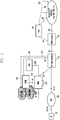
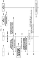
- FIG. 1 illustrates an architecture of the LTE mobile communication system.
- the radio access network (EUTRAN) of the LTE mobile communication system is composed of an evolved base station (Evolved Node B, ENB or Node B) 105, Mobility Management Entity (MME) 110, and Serving Gateway (S-GW) 115.
- Evolved Node B Evolved Node B
- MME Mobility Management Entity
- S-GW Serving Gateway
- a user equipment (UE or terminal) 100 may connect to an external network through the ENB 110, S-GW 115 and PDN Gateway (P-GW) 120.
- P-GW PDN Gateway
- Application Function (AF) 130 is an entity that provides session related information to user applications.
- the PCRF 125 is an entity for controlling policies related to user QoS. Policy and charging control (PCC) rules corresponding to a specific policy are sent to the P-GW 120 for enforcement.
- the ENB 105 is a radio access network (RAN) node, which corresponds to the RNC of the UTRAN system or the BSC of the GERAN system.
- the ENB 105 is connected with the UE 100 through a wireless channel and functions similarly to the existing RNC or BSC.
- the S-GW 115 provides data bearers, and creates and removes a data bearer under control of the MME 110.
- the MME 110 performs various control functions, and may be connected to multiple base stations.
- PCRF Policy Charging and Rules Function
- Another aspect of the present disclosure is to provide a method and apparatus that enable, when a need for an emergency call is generated in a user equipment handling a normal call, the user equipment to place an emergency call under required conditions without increasing network load.
- a method performed by a terminal in a communication system comprising: identifying a bearer associated with the terminal; determining whether the bearer associated with the terminal is needed to be deactivated in order to request an emergency bearer;deactivating the bearer locally, in case that the bearer is needed to be deactivated;and transmitting, to a mobility management entity, a first message comprising information on a status of the bearer, in case that the bearer is deactivated locally; or transmitting, to the mobility management entity, a second message including an identity of the bearer for requesting a deactivation of the bearer, in case that the bearer is needed to be deactivated and the bearer is not deactivated locally, wherein the information on the status of the bearer is set to inactive based on a result of the determination, and wherein the first message further includes information on a status of at least one other bearer set to not inactive.
- a method performed by a mobility management entity, MME, in a communication system comprising: identifying a bearer associated with a terminal; receiving, from the terminal, a first message comprising information on a status of the bearer, in case that the bearer is deactivated locally at the terminal in order to activate an emergency bearer; identifying that the bearer associated with the terminal is needed to be deactivated in order to activate the emergency bearer based on the information; and deactivating the bearer, in case that the bearer is needed to be deactivated in order to activate the emergency bearer; or receiving, from the terminal, a second message including an identity of the bearer for requesting a deactivation of the bearer, in case that the bearer is needed to be deactivated and the bearer is not deactivated locally at the terminal,wherein the information on the status of the bearer is set to inactive in case that the bearer is needed to be deactivated, and wherein the first message further includes information on
- a terminal in a communication system comprising: a transceiver; and a controller configured to: identify a bearer associated with the terminal,determine whether the bearer associated with the terminal is needed to be deactivated in order to request an emergency bearer,deactivate the bearer locally, in case that the bearer is needed to be deactivated, and transmit, to a mobility management entity via the transceiver, a first message comprising information on a status of the bearer, in case that the bearer is deactivated locally, or transmit, to the mobility management entity via the transceiver, a second message including an identity of the bearer for requesting a deactivation of the bearer, in case that the bearer is needed to be deactivated and the bearer is not deactivated locally, wherein the information on the status of the bearer is set to inactive based on a result of the determination, and wherein the first message further includes information on a status of at least one other bearer set to not
- a mobility management entity in a communication system, the MME comprising:a transceiver; and a controller configured to: identify a bearer associated with a terminal,receive, from the terminal via the transceiver, a first message comprising information on a status of the bearer, in case that the bearer is deactivated locally at the terminal in order to activate an emergency bearer, identify that the bearer associated with the terminal is needed to be deactivated in order to activate the emergency bearer based on the information, and deactivate the bearer, in case that the bearer is needed to be deactivated in order to activate the emergency bearer, or receive, from the terminal via the transceiver, a second message including an identity of the bearer for requesting a deactivation of the bearer, in case that the bearer is needed to be deactivated and the bearer is not deactivated locally at the terminal, wherein the information on the status of the bearer is set to inactive in case that the
- the description related to the LTE system may be applied to the UTRAN/GERAN system having similar system architecture.
- the ENB RAN node
- the MME may be replaced with the SGSN
- the S-GW may be omitted or be included in the SGSN
- the P-GW may correspond to the GGSN.
- Bearers in the LTE system may correspond to PDP context in the UTRAN/GERAN system.
- each communication entity may include a transceiver unit to exchange signals with another entity, and a control unit to control the transceiver unit and perform operations on the basis of signals exchanged through the transceiver unit.
- a user equipment may include a display unit to present a visual signal to a user.
- CS circuit switched voice network
- PS packet switched data network
- a particular user may have a subscription to only a PS service.
- a user having only a PS service subscription may receive an SMS service but may be not allowed to receive a CS service without a separate measure. That is, it may be assumed that a particular user is allowed to receive a PS data service and SMS service but is not allowed to receive a CS service such as a voice call (such a user is referred to as a PS-only-with-SMS user).
- a mobile terminating CS service request (e.g. a voice call) may be issued to the PS-only-with-SMS user.
- a random call for advertisement or promotion may be placed without consideration of a recipient phone number.
- a voice call may be wrongly placed to a phone number that had been previously assigned to a voice call subscriber and has been reassigned to a PS-only-with-SMS subscriber.
- a mobile terminating CS service request (voice call) is issued to a PS-only-with-SMS user
- the network may have to perform signaling such as subscriber location identification and paging.
- signaling such as subscriber location identification and paging.
- the PS-only-with-SMS user cannot receive a CS service like a voice call, such a signaling procedure is useless but merely increases network load.
- a procedure is proposed as follows.
- the operator network may determine that the user equipment is detached from a CS service (i.e. reject voice call or disallow CS service). More specifically, the following schemes may be used.
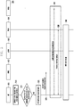
- FIG. 2 illustrates a procedure for signal exchange according to the first embodiment, wherein Home Location Register (HLR) is responsible for determination.
- HLR Home Location Register
- a first user equipment (UE1) 201 is registered as a PS-only-with-SMS terminal in at least one of the MME 202, MSC 203 and HLR 204.
- the UE1 201 registered as a PS-only-with-SMS terminal may receive only a PS data service or a SMS service.
- PS-only-with-SMS may be given to a user equipment not allowed to receive a CS service.
- a second user equipment (UE2) 206 being unaware that the UE1 201 is a PS-only-with-SMS terminal, makes a voice call to the UE1 201.
- a request for any CS service may be issued.
- the UE2 206 sends a request for placing a voice call destined for the UE1 201 to Gateway Mobile Switching Center (GMSC) 205.
- GMSC Gateway Mobile Switching Center
- the GMSC 205 Upon reception of the voice call request, at operation 225, to find an MSC/VLR at which the corresponding subscriber is located, the GMSC 205 transmits a SendRouting Information (SRI) Request message to the HLR 204.
- This message may include a service indicator indicating the requested service (voice call or SMS, or CS service other than SMS).
- the HLR 204 checks whether the request destined for the UE1 201 is SMS according to UE registration information and examines subscription information of the UE1 201. If the request destined for the UE1 201 is SMS, the HLR 204 may forward the request to the MSC 203 in which the UE1 201 is registered.
- the HLR 204 may regard the UE1 201 as being detached from the requested service.
- the HLR 204 sends a message indicating call rejection as a response to SRI to the GMSC 205.
- the call reject message may include information notifying PS-only-with-SMS subscription.
- a Send Routing Information Response message may be used. Another type message may also be used.
- the GMSC 205 Upon reception of a negative response, at operation 240, not to retry paging, the GMSC 205 stops the paging retry timer.
- the GMSC 205 sends a notification indicating failure of a voice call (CS service other than SMS) attempt to the sender network, which then notifies the sender (UE2 206) that the request for a CS service other than SMS (voice call) is denied because of recipient's PS-only-with-SMS subscription and an SMS service is available.
- the GMSC 205 may directly send such notification to the sender terminal 206, or may send such notification to a corresponding to MSC of the sender network and the MSC may forward the notification to the sender terminal 206 via RNC (BSC).
- the sender terminal 206 may store the received information or notify the user of the same.
- the sender terminal 206 may notify the user of the received information by means of sound output or screen output.
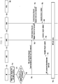
- FIG. 3 illustrates another procedure for signal exchange according to the first embodiment.
- a first user equipment (UE1) 301 is registered as a PS-only-with-SMS terminal in at least one of the MME 302, MSC 303 and HLR 304.
- the UE1 301 registered as a PS-only-with-SMS terminal may receive only a PS data service or a SMS service.
- a second user equipment (UE2) 306 being unaware that the UE1 301 is a PS-only-with-SMS terminal, makes a voice call to the UE1 301.
- the UE2 306 sends a voice call request to the GMSC 305.
- the GMSC 305 transmits an IAM message to the MSC 303 at which the UE1 301 is located.
- the IAM message may include a service indicator indicating the requested service (voice call or SMS, or CS service other than SMS).
- the MSC 303 checks whether the request destined for the UE1 301 is SMS. If the request destined for the UE1 301 is SMS, the MSC 303 sends a paging request to the MME 302 in which the UE1 301 is registered. If the request destined for the UE1 301 is a CS service (e.g. voice call), at operation 335, the MSC 303 sends a message indicating that the UE1 301 is registered as a PS-only-with-SMS terminal to the GMSC 305. Here, this message may be a call reject message, which may include a cause of rejection. At operation 335, the MSC 303 may use an RCH message or another type message to notify that the UE1 301 is registered as PS-only-with-SMS.
- CS service e.g. voice call
- the GMSC 305 After reception of a negative response, the GMSC 305 performs operation 340 and operation 345, which are identical respectively to operation 240 and operation 245 in FIG. 2 .
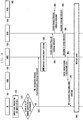
- FIG. 4 illustrates another procedure for signal exchange according to the first embodiment.
- a first user equipment (UE1) 401 is registered as a PS-only-with-SMS terminal in at least one of the MME 402, MSC 403 and HLR 404.
- the UE1 401 may receive only a PS data service or a SMS service.
- a second user equipment (UE2) 406 being unaware that the UE1 401 has a PS-only-with-SMS subscription, makes a voice call to the UE1 401.
- the UE2 406 sends a voice call request to the GMSC 405.
- the GMSC 405 transmits an IAM message to the MSC 403 at which the UE1 401 is located.
- the IAM message may include a service indicator indicating the requested service (voice call or SMS, or CS service other than SMS).
- the MSC 403 sends a paging request message to the MME 402.
- the paging request message may be a SGs_Paging_Req message, which may include an indicator to a service to be provided by paging.
- the MME 402 checks whether the request destined for the UE1 401 is SMS. If the request destined for the UE1 401 is SMS, the MME 402 may perform further processing.
- the MME 402 sends a message indicating that the UE1 401 is registered as a PS-only-with-SMS terminal to the MSC 403.
- this message may be a paging reject message, which may include a cause of rejection.
- the MME 402 may also use a SGs paging reject message or another type message.
- the MSC 403 Upon reception of a negative response such as paging reject, at operation 445, not to retry paging, the MSC 403 stops the paging retry timer.
- the MSC 403 notifies the GMSC 405 of voice call rejection.
- a call reject message including a cause of rejection may be sent to the GMSC 405 to notify the sender network of failure of a voice call attempt.
- operation 455 and operation 460 in the sender network are performed in a manner identical respectively to operation 240 and operation 245 in FIG. 2 .
- the maximum number of simultaneously activatable bearers in a user equipment may be limited according to implementation. Typical user equipments may simultaneously activate up to one, three or five bearers.
- the number of simultaneously active bearers may exceed the maximum number of bearers supportable by the user equipment when an emergency call is placed in a state wherein the number of normal bearers currently active for system attachment has reached the maximum number of supportable bearers, or when multiple bearers needed to provide an emergency service are simultaneously created (for example, while the maximum number of supportable bearers is three, the number of active normal bearers is two and the number of emergency bearers needed is two). In this case, for emergency service provisioning, it is necessary to release normal bearers and create emergency bearers.
- the user equipment may perform normal bearer cleanup first and then perform emergency bearer setup, or may simultaneously issue an emergency bearer setup request and a normal bearer cleanup request.
- the user equipment may send a normal bearer deactivation request to the network, or may locally deactivate normal bearers and notify the core network of a bearer context state through TAU.
- the core network e.g. MME
- the core network may automatically perform normal bearer cleanup for the user equipment. More specifically, the following schemes may be used.
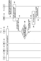
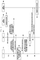
- FIG. 5 illustrates a procedure for signal exchange according to the second embodiment.
- FIG. 5 depicts emergency service provisioning through the attach procedure.
- a UE 501 may exchange signals with a network composed of the MME 502, S-GW 503, P-GW 504 and HSS 505.
- the UE 501 may exchange signals with the network via a base station (ENB).
- ENB base station
- the UE 501 detects a user request for an emergency service.
- the UE 501 identifies the number of currently active bearers.
- the number of currently active bearers may be the number of normal bearers.
- the UE 501 may determine whether some or all of the currently active bearers are to be deactivated on the basis of the number of currently active bearers, the number of bearers to be used for the emergency service, and the number of simultaneously supportable bearers.
- the UE 501 may determine that the number of simultaneously active bearers fails to accommodate the number of bearers to be used for the emergency service.
- the UE 501 may exchange signals with the MME 502 to establish a call for the emergency service .
- the UE 501 performs local detach.
- the UE 501 may autonomously conduct the local detach procedure.
- the UE 501 performs a re-attach procedure for the emergency service in cooperation with the MME 502.
- This procedure maybe initiated by sending an attach request, and the attach request may include an indication to the service or call type.
- the core network Upon reception of the attach request from the UE 501, at operation 530 and at operation 535, the core network identifies emergency attach from the attach request, and performs cleanup of existing normal bearers and generation of emergency bearers by means of authentication and authorization, and bearer context setup.
- an IMS call is set up between the UE 501 and the core network.
- FIG. 6 illustrates another procedure for signal exchange according to the second embodiment.
- FIG. 6 depicts a scheme in which the user equipment explicitly makes a normal bearer cleanup request.
- a UE 601 may exchange signals with a network composed of the MME 602, S-GW 603 and P-GW 604.
- the UE 601 may exchange signals with the network via a base station (ENB).
- ENB base station
- the UE 601 detects a user request for an emergency service.
- the UE 601 identifies the number of currently active bearers.
- the number of currently active bearers may be the number of normal bearers.
- the UE 601 may determine whether some or all of the currently active bearers are to be deactivated on the basis of the number of currently active bearers, the number of bearers to be used for the emergency service, and the number of simultaneously supportable bearers.
- the UE 601 may determine that the number of simultaneously active bearers fails to accommodate the number of bearers to be used for the emergency service.
- the UE 601 may exchange signals with the MME 602 to establish a call for the emergency service.
- the UE 601 sends a request for releasing a normal bearer or normal PDN connection to the core network.
- this request may be sent to the MME 602 through a bearer resource modification request or PDN disconnection request.
- the MME 602 Upon reception of the request, at operation 625, the MME 602 forwards the received request to the S-GW 603 through a bearer resource command or a delete session request.
- the S-GW 603 Upon reception of the request, at operation 630, the S-GW 603 forwards the received request to the P-GW 605 through a bearer resource command or a delete session request.
- a response to the request is sent by the P-GW 604 via the S-GW 603 and the MME 602 to the UE 601.
- the UE 601 may be detached.
- the UE 601 sends an Attach request or PDN connectivity request to the MME 602.
- This request may include type information indicating "emergency”.
- an emergency PDN connectivity request may be sent. In the event that all bearers have been released, as the UE 601 is detached, an emergency attach request may be sent.
- At operation 660 at least one of the emergency attach procedure and the emergency PDN connection procedure may be performed.
- an IMS call is set up.
- the UE 601 may locally deactivate existing bearers and notify the core network of this deactivation through a TAU procedure. More specifically, in response to a user request for an emergency service, when some or all of existing bearers are to be deactivated, the UE 601 selects bearers to be deactivated and sends a TAU request message containing information on the remaining active EPS bearers (except for the selected bearers) to the core network (active bits of the EPS bearer context status are set in the TAU request message). The UE 601 may also send a TAU request message containing bearer information (bearers to be deactivated are marked as inactive and bearers to be kept are marked as active) to the core network.
- the UE 601 may notify the core network of the emergency service request by setting the EPS update type of the TAU request.
- the UE 601 may notify the core network of the emergency service request by using an additional update type of the TAU request.
- the UE 601 may also notify the core network of the emergency service request by using a separate emergency indicator of the TAU request.
- the UE 601 may notify the core network of S1/S5 setup for the following emergency service by setting the active flag of the TAU request.
- the MME 602 may be aware that the UE 601 has changed the bearer context for the emergency service.
- the MME 602 compares the pre-stored EPS bearer context status with the EPS bearer context status in the TAU request received from the UE 601 and may perform bearer cleanup if an EPS bearer to be deactivated is present.
- the MME 602 may send a TAU accept response to the UE 601 before completion of bearer cleanup.
- the UE 601 Upon reception of a TAU accept response, the UE 601 maybe aware of completion of requested bearer context status update, and may perform a subsequent procedure for the emergency service.
- the UE 601 selects bearers to be deactivated and sends a TAU request containing information on the remaining active EPS bearers (except for the selected bearers) to the core network (active bits of the EPS bearer context status are set in the TAU request message).
- the UE 601 may also send a TAU request message containing bearer information (bearers to be deactivated are marked as inactive and bearers to be kept are marked as active) to the core network.
- the UE 601 has to establish an RRC connection with the ENB.
- the UE 601 may send an RRC connection setup request whose establishment cause is set to "emergency".
- the ENB forwards the TAU request message contained in an RRC message received from the UE 601 through S1-AP Initial UE message.
- the ENB may forward this together with the TAU request message.
- the MME 602 may be aware that the UE 601 has sent the TAU request for an emergency service. Thereafter, subsequent operations may be processed as described before.
- the UE 601 is depicted as notifying the network of information on locally deactivated bearers using a TAU message.
- the same procedure may be applied to 2G/3G networks using a Routing Area Update (RAU) message.
- the UE 601 may send an Extended Service Request (ESR) message having bearer status information instead of a TAU message having bearer status information.
- ESR Extended Service Request
- FIG. 7 illustrates another procedure for signal exchange according to the second embodiment.
- FIG. 7 depicts a signal exchange scheme in which cleanup of existing bearers and creation of new emergency bearers are simultaneously performed.
- a UE 701 may exchange signals with a network composed of the ENB 702, MME 703, S-GW 704 and P-GW 705.
- the UE 701 detects a user request for an emergency service.
- the UE 701 identifies the number of currently active bearers.
- the number of currently active bearers may be the number of normal bearers.
- the UE 701 may determine whether some or all of the currently active bearers are to be deactivated on the basis of the number of currently active bearers, the number of bearers to be used for the emergency service, and the number of simultaneously supportable bearers.
- the UE 701 may determine that the number of simultaneously active bearers fails to accommodate the number of bearers to be used for the emergency service.
- the UE 701 may exchange signals with the MME 703 to establish a call for the emergency service .
- the UE 701 selects bearers to be deactivated and sends a PDN connectivity request message containing information on the remaining active EPS bearers (except for the selected bearers) to the MME 703 (active bits of the EPS bearer context status are set in the PDN connectivity request message) .
- the UE 701 may also send a PDN connectivity request message containing bearer information (bearers to be deactivated are marked as inactive and bearers to be kept are marked as active) to the MME 703.
- the UE 701 may select bearers to be removed according to a criteria based on ARP, QCI, default/dedicated bearer (a dedicated bearer is removed), or inactivity duration.
- the MME 703 may be aware that the UE 701 has changed the bearer context for the emergency service.
- the MME 703 compares the pre-stored EPS bearer context status with the EPS bearer context status in the PDN connectivity request received from the UE 701 and may perform bearer cleanup if an EPS bearer to be deactivated is present.
- the MME 602 may also perform bearer cleanup on the basis of information received at operation 715.
- the MME 703 may perform a PDN connection creation procedure for the emergency service.
- the MME 703 sends a Create Session Request to the S-GW 704.
- This Create Session Request may contain IDs of bearers to be removed.
- the S-GW 704 forwards the Create Session Request received at operation 725 to the P-GW 705.
- each node sends or forwards a response message.
- the ENB 702 may send an RRC connection Reconfiguration to the UE 701. This RRC connection Reconfiguration may contain a DBR list.
- an IMS call is set up between the UE 701 and core network.
- FIG. 8 illustrates another procedure for signal exchange according to the second embodiment.
- a UE 801 requests the network to clean up existing normal bearers and to create bearers for an emergency service.
- the UE 601 may exchange signals with a network composed of the ENB 802, MME 803, S-GW 804 and P-GW 805.
- Operation 810 and operation 815 are identical respectively to operation 710 and operation 715 in FIG. 7 .
- the UE 801 sends an Emergency PDN connectivity request containing a cleanup indicator to existing bearers.
- This request may also include information on the number of bearers simultaneously supportable by the UE 801.
- the MME 803 may autonomously perform bearer cleanup. In the case wherein the number of supportable bearers in the UE 801 is not known to the core network when the UE 801 has issued a bearer cleanup request, the MME 803 may simply remove all normal bearers.
- the MME 803 may be aware of the maximum number of simultaneously supportable bearers in the UE 801 according to user subscription information.
- the context table in the UE 801 may have a mapping to the maximum number of supportable bearers based on ISMI, or the maximum number of active bearers may be known according to the model of the UE 801 based on IMEISV.
- the MME 803 may have to store mappings for UE models based on IMEISV and the maximum number of active bearers in each UE model.
- the operator may update UE information in the HSS or may set information on the IMEISV-based model of the UE 801 and the maximum number of bearers corresponding to the model in the MME 803 through O&M configuration or the like.
- the MME 803 may determine that some or all of normal bearers are to be removed on the basis of information on the UE 801 and the maximum number of supportable bearers. When only some of normal bearers are to be removed, selection of bearers to be removed may be performed according to a criteria based on ARP, QCI, default/dedicated bearer (a dedicated bearer is removed), or inactivity duration.
- the core network removes corresponding active normal bearers (bearer cleanup from the S-GW 804 to the P-GW 805) and creates emergency bearers/sessions.
- cleanup of existing bearers and creation of new emergency bearers may be simultaneously performed or separately performed in sequence.
- a list of bearers to be removed or a cleanup indicator indicating removal of all normal bearers maybe inserted in the Create session request message for emergency bearer creation.
- the MME 803 notifies the ENB 802 of information on removed bearers and newly created bearers (bearer ID, bearer QoS, S5 TEID or the like) .
- the ENB 802 updates data radio bearers related to the UE 801 accordingly.
- the core network may remove the indicated active normal bearers (bearer cleanup from the S-GW 804 to the P-GW 805) and perform emergency bearer/session creation.
- cleanup of existing bearers and creation of new emergency bearers may be simultaneously performed or separately performed in sequence.
- a list of bearers to be removed or a cleanup indicator indicating removal of all normal bearers may be inserted in the Create session request message for emergency bearer creation.
- the MME 803 notifies the ENB 802 of information on removed bearers and newly created bearers (bearer ID, bearer QoS, S5 TEID or the like) .
- the ENB 802 updates data radio bearers related to the UE 801 accordingly. Finally, this update is known to the UE 801.
- merging of the EMM process and the ESM process is proposed. That is, a TAU/RAU request message or ESR message containing an ESM message container is transmitted.
- an ESM request message (e.g. PDN connectivity request) created by the UE 801 may be contained in the ESM message container.
- the UE 801 upon emergency service initiation, sends information on locally deactivated bearers through a TAU/RAU request message or an ESR message, whose ESM message container includes a PDN connectivity request.
- the UE 801 inserts information on locally deactivated bearers or information on the remaining active bearers after deactivation in the EPS bearer context status IE of a TAU request, RAU request or ESR message, inserts a PDN connectivity request for the emergency service in the ESM message container thereof, and sends the TAU request, RAU request or ESR message to the MME 803.
- the MME 803 may not only perform bearer cleanup for the UE 801 according to the above embodiments but also handle a PDN connection creation request using the PDN connectivity request contained in the ESM message container.
- information elements contained in each signal may be used interchangeably.
- the core network node may redirect user equipments being served so that the user equipments can be served by another core network node.
- This process may be realized through a procedure performed by a base station node to newly select a core network node for a user equipment and through a procedure to register UE information in the core network node.
- congestion may be not resolved.
- the core network node serving a user equipment is changed after a new core network node is selected by the base station node, it is necessary to register UE information in the new core network node.
- making an information request to the previous core network node may exacerbate conditions of the previous core network node already in congestion.
- a core network node in congestion may notify a user equipment of difficulty of service provisioning owing to congestion through NAS layer information.
- the user equipment does not provide information enabling identification of the previous core network node (e.g. S-TMSI, GUTI, GUMMEI, or P-TMSI) to the lower layer (AS layer) during reconfiguration of core network registration.
- the AS layer of the user equipment cannot provide information thereon when an RRC connection is established with the base station, causing the base station to select a new core network node for the user equipment.
- a NAS request message (e.g. attach request) from the user equipment is delivered to the newly selected core network node via the base station.
- the user equipment may provide the new core network node with information (or indicator) that directs the new core network node to directly communicate with the HSS to thereby configure UE context information.
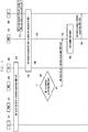
- FIG. 9 illustrates a procedure for signal exchange according to the third embodiment.
- a UE 901 may exchange signals with the MME/SGSN 903 or 904 via the RAN 902.
- the MME/SGSN 903 or 904 may be referred to as old MME/SGSN 903 (to which a connection has been made) or referred to as new MME/SGSN 904 (to which a connection will be made).
- change of the MME/SGSN may also be triggered by a cause other than congestion.
- congestion is generated in the old MME/SGSN 903. Congestion may be caused by an increase in traffic, operational failure of some devices or the like.
- the UE 901 sends a NAS request message (e.g. TAU request or attach request) to a core network node in congestion (referred to as old core network node) .
- a NAS request message e.g. TAU request or attach request
- old core network node a core network node in congestion
- the old core network node sends an NAS response or reject message (e.g. TAU reject or attach reject) together with information indicating rejection of the request owing to congestion or indicating necessity of UE re-registration as loaded state to the UE 901.
- the S1-AP message (Downlink NAS Transport), which encapsulates the NAS message and is sent to the RAN 902 (base station), may further include information indicating necessity of releasing an RRC connection between the UE 901 and RAN 902 after delivery of the NAS message (e.g. immediate release required indicator).
- the RAN 902 sends an RRC message (DLInformationTransfer), which contains the message received from the core network node, to the UE 901.
- the RRC message may contain a congestion notification and timer information.
- the RRC connection Upon reception of a request for immediate release of the RRC connection, at operation 930, the RRC connection is immediately released after message delivery.
- the RRC connection is released because, as the RAN 902 reselects a core network node for the UE 901 during RRC connection setup, if an existing RRC connection is reused when the UE 901 makes a NAS request, the old core network node may be reused.
- a timer value may be inserted in a NAS response/reject message sent by the core network node to the UE 901 or in an RRC message (DLInformationTransfer) sent by the RAN 902 to the UE 901.
- This timer value acts as a protection interval needed by the RAN 902 to release an existing RRC connection. That is, when a timer value is received through a core network node or an RRC message, the UE 901 may make a NAS request after expiration of the corresponding timer.
- the NAS layer of the UE 901 prevents delivery of information enabling identification of the old core network node (e.g. S-TMSI, GUTI, GUMMEI or P-TMSI) to the lower layer.
- the old core network node e.g. S-TMSI, GUTI, GUMMEI or P-TMSI
- RRC connection request/setup are performed.
- the AS layer of the UE 901 does not send information enabling identification of the old core network node (e.g. MME routing information) to the RAN 902.
- the RAN 902 receives an RRC connection setup complete message.
- the RAN 902 selects a new core network node.
- the RAN 902 forwards the contained NAS request message to the new core network node.
- the new core network node Upon reception of the NAS request message for the UE 901, the new core network node has to perform a procedure for obtaining context information of the UE 901.
- the new core network node may send a request for context information of the UE 901 to the old core network node if necessary by use of an identifier (GUTI, or oldGUTI) inserted by the UE 901 in the NAS request message.
- GUI identifier
- the old core network node may notify the new core network node of the congestion state through message exchange between core network nodes such as overload indication, or 2) when the new core network node sends an identification request for context information, the old core network node may notify the new core network node of the congestion state through a response/rejection to the request.
- the new core network node may be aware that the old core network node is overloaded and may store the notification for later use.
- the core network performs a procedure of identity request/response to obtain the IMSI of the UE 901.
- the core network receives the IMSI from the UE 901 and performs UE context setup and necessary registration using the received IMSI.
- FIG. 10 illustrates another procedure for signal exchange according to the third embodiment.
- a UE 1001 may exchange signals with the MME/SGSN 1003 or 1004 via the RAN 1002.
- the MME/SGSN 1003 or 1004 maybe referred to as old MME/SGSN 1003 (to which a connection has been made) or referred to as new MME/SGSN 1004 (to which a connection will be made).
- change of the MME/SGSN may also be triggered by a cause other than congestion.
- Operations 1010 to 1040 correspond respectively to operations 910 to 940 in FIG. 9 .
- the UE 1001 generates a NAS request (attach request) containing an indication to overload of the old core network node or to preference for core network change at the NAS layer and sends the NAS request to the RAN 1002 (base station).
- the RAN 1002 selects a new core network node (MME/SGSN 1004) and sends an Initial UE message to the MME/SGSN 1004.
- the Initial UE message may contain an indication notifying re-attachment due to core network overload.
- the new core network node Upon reception of the NAS request message for the UE 1001, at operation 1060, the new core network node has to perform a procedure for obtaining context information of the UE 1001.
- the new core network node may be aware that the old core network node is overloaded and may store the notification for later use. If necessary, the new core network node may perform a procedure of identity request/response to obtain the IMSI of the UE 1001. At operation 1065, the core network receives the IMSI from the UE 1001 and performs UE context setup and necessary registration using the received IMSI.
- FIG. 11 illustrates another procedure for signal exchange according to the third embodiment.
- a UE 1101 may exchange signals with the MME/SGSN 1103 or 1104 via the RAN 1102.
- the MME/SGSN 1103 or 1104 maybe referred to as old MME/SGSN 1103 (to which a connection has been made) or referred to as new MME/SGSN 1104 (to which a connection will be made).
- change of the MME/SGSN may also be triggered by a cause other than congestion.
- Operations 1110 to 1150 correspond respectively to operations 910 to 950 in FIG. 9 .
- the UE 1101 generates a NAS request (attach request) containing IMSI as UE ID instead of GUTI or old GUTI at the NAS layer when the present NAS request is to be generated owing to overload of the old core network node or preference for core network change, and sends the NAS request.
- the new core network node does not send a request for UE context information to the old core network node and may perform UE context setup for the UE 1101 and necessary registration on the basis of the IMSI.
- the RAN 1102 sends an Initial UE message containing the NAS request and IMSI of the UE 1101.
- necessary registration is performed.
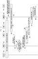
- FIG. 12 illustrates another procedure for signal exchange according to the third embodiment.
- a UE 1201 may exchange signals with the MME/SGSN 1203 or 1204 via the RAN 1202.
- the MME/SGSN 1203 or 1204 maybe referred to as old MME/SGSN 1203 (to which a connection has been made) or referred to as new MME/SGSN 1204 (to which a connection will be made).
- change of the MME/SGSN may also be triggered by a cause other than congestion.
- FIGS. 9 to 11 are related to a case wherein the UE 1201 explicitly sends a NAS request to a core network node
- the embodiment described in FIG. 12 may also be applied to a case wherein the UE 1201 does not explicitly send a NAS request.
- the UE 1201 upon determining that a core network node is overloaded, the UE 1201 is notified of necessity of core network node reconfiguration via the RAN 1202 and is registered through a new core network node using a procedure similar to those depicted in FIGS. 9 to 11 .
- the UE 1201, RAN 1202 and old MME/SGSN 1203 operate in connected mode.
- a core network node (old MME/SGSN 1203) detects overload.
- the core network node sends a command message to the RAN 1202.
- the command message contains information indicating necessity of connection release as to the UE 1201 for load balancing.
- the RAN 1202 Upon reception of the command message, at operation 1225, the RAN 1202 sends an RRC connection release command indicating necessity of core network change for load balancing to the UE 1201. Operations after RRC connection release are similar to those after RRC connection release described in FIGS. 9 to 11 , and a detailed description thereof is omitted.
Claims (15)
- Ein Verfahren, das von einem Endgerät (100) in einem Kommunikationssystem durchgeführt wird, wobei das Verfahren umfasst:Identifizieren eines mit dem Endgerät verbundenen Trägers;Bestimmen, ob der mit dem Endgerät verbundene Träger deaktiviert werden muss, um einen Notfallträger anzufordern;Deaktivieren des Trägers lokal, für den Fall, dass der Träger deaktiviert werden muss; und Senden einer ersten Nachricht an eine Mobilitätsmanagement-Einheit (110), die Informationen über einen Status des Trägers enthält, für den Fall, dass der Träger lokal deaktiviert wird; oderSenden einer zweiten Nachricht, die eine Identität des Trägers enthält, an die Mobilitätsmanagement-Einheit, um eine Deaktivierung des Trägers anzufordern, falls der Träger deaktiviert werden muss und der Träger nicht lokal deaktiviert wird,wobei die Informationen über den Status des Trägers basierend auf einem Ergebnis der Bestimmung auf inaktiv gesetzt wird, undwobei die erste Nachricht weiterhin Informationen über einen Status von mindestens einem anderen auf nicht-inaktiv gesetzten Träger enthält.
- Das Verfahren nach Patentanspruch 1, wobei die erste Nachricht eine Tracking-Area-Update-Anforderungsnachricht enthält.
- Das Verfahren nach Patentanspruch 1, ferner umfassend:Senden einer Attach-Anforderungsnachricht an die Mobilitätsmanagement-Einheit, die ein Anforderungstypelement enthält, das anzeigt, dass das Endgerät eine Konnektivität zu einem Paketdatennetz für einen Notfallträgerdienst anfordert; undEinrichten des Notfallträgers für den Notfallträgerdienst mit der Mobilitätsmanagement-Einheit.
- Das Verfahren nach Patentanspruch 1, wobei die zweite Nachricht eine Trägerressourcenänderungsanforderungsnachricht oder eine Paketdatennetz-, PDN-, Trennungsanforderungsnachricht enthält.
- Ein Verfahren, das von einer Mobilitätsmanagement-Einheit, MME (110), in einem Kommunikationssystem durchgeführt wird, wobei das Verfahren umfasst:Identifizieren eines einem Endgerät (100) zugeordneten Trägers;Empfangen einer ersten Nachricht, die Informationen über einen Status des Trägers enthält, vom Endgerät für den Fall, dass der Träger lokal am Endgerät deaktiviert wird, um einen Notfallträger zu aktivieren;Identifizieren, dass der dem Endgerät zugeordnete Träger deaktiviert werden muss, um den Notfallträger basierend auf den Informationen zu aktivieren; undDeaktivieren des Trägers, für den Fall, dass der Träger deaktiviert werden muss, um den Notfallträger zu aktivieren; oderEmpfangen einer zweiten Nachricht vom Endgerät, die eine Identität des Trägers enthält, um eine Deaktivierung des Trägers anzufordern, für den Fall, dass der Träger deaktiviert werden muss und der Träger nicht lokal am Endgerät deaktiviert wird,wobei die Informationen über den Status des Trägers auf inaktiv gesetzt werden für den Fall, dass der Träger deaktiviert werden muss, undwobei die erste Nachricht weiterhin Informationen über einen Status von mindestens einem anderen auf nicht-inaktiv gesetzten Träger enthält.
- Das Verfahren nach Patentanspruch 5, wobei die erste Nachricht eine Tracking-Area-Update-Anforderungsnachricht enthält.
- Das Verfahren nach Patentanspruch 5, ferner umfassend:Empfangen einer Attach-Anforderungsnachricht vom Endgerät, die ein Anforderungstypelement enthält, das anzeigt, dass das Endgerät eine Konnektivität zu einem Paketdatennetz für einen Notfallträgerdienst anfordert; undEinrichten des Notfallträgers für den Notfallträgerdienst mit dem Endgerät.
- Das Verfahren nach Patentanspruch 5, wobei die zweite Nachricht eine Trägerressourcenänderungsanforderungsnachricht oder eine Paketdatennetz-, PDN-, Trennungsanforderungsnachricht enthält.
- Ein Endgerät (100) in einem Kommunikationssystem, wobei das Endgerät umfasst:einen Transceiver; undeine Steuerung, die konfiguriert ist, zum:Identifizieren eines dem Endgerät zugeordneten Trägers,Bestimmen, ob der dem Endgerät zugeordnete Träger deaktiviert werden muss, um einen Notfallträger anzufordern,Deaktivieren des Trägers lokal, für den Fall, dass der Träger deaktiviert werden muss, undSenden einer ersten Nachricht, die Informationen über einen Status des Trägers enthält, über den Transceiver an eine Mobilitätsmanagement-Einheit (110) für den Fall, dass der Träger lokal deaktiviert wird, oderSenden einer zweiten Nachricht, die eine Identität des Trägers enthält, über den Transceiver an die Mobilitätsmanagement-Einheit, um eine Deaktivierung des Trägers anzufordern, für den Fall, dass der Träger deaktiviert werden muss und der Träger nicht lokal deaktiviert wird,wobei die Informationen über den Status des Trägers basierend auf einem Ergebnis der Bestimmung auf inaktiv gesetzt werden, undwobei die erste Nachricht weiterhin Informationen über einen Status von mindestens einem anderen auf nicht-inaktiv gesetzten Träger enthält.
- Das Endgerät nach Patentanspruch 9, wobei die erste Nachricht eine Tracking-Area-Update-Anforderungsnachricht enthält.
- Das Endgerät nach Patentanspruch 9, wobei die Steuerung ferner so konfiguriert ist, dass sie an die Mobilitätsmanagement-Einheit über den Transceiver eine Attach-Anforderungsnachricht sendet, die ein Anforderungstypelement enthält, das anzeigt, dass das Endgerät eine Konnektivität zu einem Paketdatennetz für einen Notfallträgerdienst anfordert, und den Notfallträger für den Notfallträgerdienst mit der Mobilitätsmanagement-Einheit einrichtet.
- Das Endgerät nach Patentanspruch 9, wobei die zweite Nachricht eine Trägerressourcenänderungsanforderungsnachricht oder eine Paketdatennetz-, PDN-, Trennungsanforderungsnachricht enthält.
- Eine Mobilitätsmanagement-Einheit, MME (110), in einem Kommunikationssystem, wobei die MME umfasst:einen Transceiver; undeine Steuerung, die konfiguriert ist, zum:Identifizieren eines einem Endgerät (100) zugeordneten Trägers,Empfangen einer ersten Nachricht, die Informationen über einen Status des Trägers enthält, über den Transceiver vom Endgerät, für den Fall, dass der Träger lokal am Endgerät deaktiviert wird, um einen Notfallträger zu aktivieren,Identifizieren, dass der dem Endgerät zugeordnete Träger deaktiviert werden muss, um den Notfallträger basierend auf den Informationen zu aktivieren, undDeaktivieren des Trägers, für den Fall, dass der Träger deaktiviert werden muss, um den Notfallträger zu aktivieren, oderEmpfangen einer zweiten Nachricht, die eine Identität des Trägers enthält, über den Transceiver von dem Endgerät, um eine Deaktivierung des Trägers anzufordern, für den Fall, dass der Träger deaktiviert werden muss und der Träger nicht lokal am Endgerät deaktiviert wird,wobei die Informationen über den Status des Trägers auf inaktiv gesetzt werden, für den Fall, dass der Träger deaktiviert werden muss, undwobei die erste Nachricht weiterhin Informationen über einen Status von mindestens einem anderen auf nicht-inaktiv gesetzten Träger enthält.
- Die MME nach Patentanspruch 13, wobei die erste Nachricht eine Tracking-Area-Update-Anforderungsnachricht enthält.
- Die MME nach Patentanspruch 13, wobei die zweite Nachricht eine Trägerressourcenänderungsanforderungsnachricht oder eine Paketdatennetz-, PDN-, Trennungsanforderungsnachricht enthält.
Priority Applications (1)
| Application Number | Priority Date | Filing Date | Title |
|---|---|---|---|
| EP21179267.6A EP3897032A1 (de) | 2012-03-08 | 2013-03-08 | Verfahren zur steuerung von diensten in einem drahtloskommunikationssystem |
Applications Claiming Priority (5)
| Application Number | Priority Date | Filing Date | Title |
|---|---|---|---|
| US201261608580P | 2012-03-08 | 2012-03-08 | |
| US201261612484P | 2012-03-19 | 2012-03-19 | |
| US201261614470P | 2012-03-22 | 2012-03-22 | |
| EP13758097.3A EP2824981B1 (de) | 2012-03-08 | 2013-03-08 | Verfahren zum steuern eines dienstes in einem funkkommunikationssystem |
| PCT/KR2013/001892 WO2013133663A1 (ko) | 2012-03-08 | 2013-03-08 | 무선 통신 시스템에서 서비스를 제어하기 위한 방법 |
Related Parent Applications (1)
| Application Number | Title | Priority Date | Filing Date |
|---|---|---|---|
| EP13758097.3A Division EP2824981B1 (de) | 2012-03-08 | 2013-03-08 | Verfahren zum steuern eines dienstes in einem funkkommunikationssystem |
Related Child Applications (2)
| Application Number | Title | Priority Date | Filing Date |
|---|---|---|---|
| EP21179267.6A Division-Into EP3897032A1 (de) | 2012-03-08 | 2013-03-08 | Verfahren zur steuerung von diensten in einem drahtloskommunikationssystem |
| EP21179267.6A Division EP3897032A1 (de) | 2012-03-08 | 2013-03-08 | Verfahren zur steuerung von diensten in einem drahtloskommunikationssystem |
Publications (2)
| Publication Number | Publication Date |
|---|---|
| EP3509387A1 EP3509387A1 (de) | 2019-07-10 |
| EP3509387B1 true EP3509387B1 (de) | 2021-07-28 |
Family
ID=49117069
Family Applications (3)
| Application Number | Title | Priority Date | Filing Date |
|---|---|---|---|
| EP19158736.9A Active EP3509387B1 (de) | 2012-03-08 | 2013-03-08 | Verfahren zur steuerung von diensten in einem drahtloskommunikationssystem |
| EP21179267.6A Pending EP3897032A1 (de) | 2012-03-08 | 2013-03-08 | Verfahren zur steuerung von diensten in einem drahtloskommunikationssystem |
| EP13758097.3A Active EP2824981B1 (de) | 2012-03-08 | 2013-03-08 | Verfahren zum steuern eines dienstes in einem funkkommunikationssystem |
Family Applications After (2)
| Application Number | Title | Priority Date | Filing Date |
|---|---|---|---|
| EP21179267.6A Pending EP3897032A1 (de) | 2012-03-08 | 2013-03-08 | Verfahren zur steuerung von diensten in einem drahtloskommunikationssystem |
| EP13758097.3A Active EP2824981B1 (de) | 2012-03-08 | 2013-03-08 | Verfahren zum steuern eines dienstes in einem funkkommunikationssystem |
Country Status (7)
| Country | Link |
|---|---|
| US (5) | US9629021B2 (de) |
| EP (3) | EP3509387B1 (de) |
| JP (3) | JP2015513864A (de) |
| KR (2) | KR102130629B1 (de) |
| CN (2) | CN104160762B (de) |
| AU (1) | AU2013228148B2 (de) |
| WO (1) | WO2013133663A1 (de) |
Families Citing this family (31)
| Publication number | Priority date | Publication date | Assignee | Title |
|---|---|---|---|---|
| GB2509072B (en) * | 2012-12-19 | 2015-08-05 | Samsung Electronics Co Ltd | Bearer management |
| KR101703789B1 (ko) | 2013-01-24 | 2017-02-07 | 후아웨이 테크놀러지 컴퍼니 리미티드 | 서비스 처리 방법, 시스템 및 관련 장치 |
| CN106465080B (zh) | 2014-04-15 | 2020-02-07 | 诺基亚通信公司 | 用于基于承载的系统和无承载系统之间的互通的方法和装置 |
| KR102412234B1 (ko) | 2014-05-08 | 2022-06-23 | 인터디지탈 패튼 홀딩스, 인크 | Ue를 전용 코어 네트워크 노드에 리디렉트하기 위한 방법들 및 이동성 관리 엔티티(mme) |
| CN106537879B (zh) * | 2014-06-11 | 2020-01-17 | 康维达无线有限责任公司 | 用于本地内容重定向的映射服务 |
| WO2016032304A1 (en) | 2014-08-29 | 2016-03-03 | Samsung Electronics Co., Ltd. | Method and apparatus for communicating using unlicensed bands in mobile communication system |
| KR101905941B1 (ko) | 2014-11-13 | 2018-10-11 | 주식회사 케이티 | Wlan 캐리어를 이용한 데이터 송수신 방법 및 그 장치 |
| US9967915B2 (en) * | 2015-05-07 | 2018-05-08 | Samsung Electronics Co., Ltd | Method of handling multiple PDN/PDP disconnection requests on the same APN |
| CN104883706A (zh) * | 2015-05-08 | 2015-09-02 | 大唐移动通信设备有限公司 | 一种寻呼失败处理方法及装置 |
| US10524171B2 (en) * | 2015-06-16 | 2019-12-31 | Qualcomm Incorporated | Reselection between regular and dedicated core networks |
| JP6515247B2 (ja) * | 2015-10-14 | 2019-05-15 | テレフオンアクチーボラゲット エルエム エリクソン(パブル) | ネットワーク接続をハンドリングするための方法及びノード |
| CN108370604B (zh) * | 2015-11-17 | 2021-08-17 | Lg 电子株式会社 | 无线通信系统中支持扩展空闲模式不连续接收激活的方法及其装置 |
| WO2017086647A1 (ko) * | 2015-11-19 | 2017-05-26 | 에스케이텔레콤 주식회사 | 이동통신 시스템에서 코어 네트워크를 선택하는 방법 및 장치 |
| KR102373871B1 (ko) * | 2015-12-09 | 2022-03-14 | 삼성전자주식회사 | 무선 통신 시스템에서 멀티 서비스를 위한 장치 및 방법 |
| KR102168676B1 (ko) | 2016-03-23 | 2020-10-21 | 엘지전자 주식회사 | 무선 통신 시스템에서 트래킹 영역 업데이트 방법 및 이를 위한 장치 |
| WO2018008977A1 (en) | 2016-07-05 | 2018-01-11 | Samsung Electronics Co., Ltd. | A method of handling control plane data in a wireless network |
| CN108347735B (zh) * | 2017-01-24 | 2023-07-14 | 中兴通讯股份有限公司 | 过载控制方法及装置 |
| US10158524B2 (en) * | 2017-02-10 | 2018-12-18 | Verizon Patent And Licensing Inc. | System and method for enhanced network event monitoring and reporting |
| JP2018157506A (ja) * | 2017-03-21 | 2018-10-04 | 株式会社Nttドコモ | スライス割当方法及び移動通信システム |
| CN106792612A (zh) * | 2017-03-29 | 2017-05-31 | 努比亚技术有限公司 | 一种无卡紧急呼叫处理方法及终端 |
| CN108809565B (zh) * | 2017-05-04 | 2020-08-14 | 华为技术有限公司 | 消息的传输方法、及设备 |
| CN107567043B (zh) * | 2017-10-10 | 2021-07-30 | 成都欧珀通信科技有限公司 | 检测终端接入的方法及相关产品 |
| EP3711373B1 (de) * | 2017-11-17 | 2021-03-31 | Telefonaktiebolaget LM Ericsson (Publ) | Verfahren, vorrichtung und systeme im zusammenhang mit ue-inaktivität |
| CN111448843B (zh) * | 2017-11-17 | 2023-08-15 | Lg电子株式会社 | 发起服务请求过程的方法和用户设备 |
| CN110393022A (zh) * | 2018-02-22 | 2019-10-29 | 联发科技(新加坡)私人有限公司 | 移动通信中系统间切换的追踪区域更新进程改善 |
| KR102490382B1 (ko) | 2018-05-10 | 2023-01-19 | 삼성전자 주식회사 | 차세대 이동 통신 시스템에서 페이징을 지원하는 방법 및 장치 |
| US11122471B2 (en) * | 2019-10-04 | 2021-09-14 | T-Mobile Usa, Inc. | On-demand circuit-switched (CS) network registration |
| EP4133800A4 (de) * | 2020-04-07 | 2024-01-03 | Qualcomm Inc | Verfahren zum schnellen wiederherstellen von anruffällen in 5g-nsa |
| KR20220042796A (ko) | 2020-09-28 | 2022-04-05 | 삼성전자주식회사 | 망 연동 시 네트워크 슬라이스를 지원하는 방법 및 장치 |
| US11570737B1 (en) * | 2021-08-13 | 2023-01-31 | At&T Intellectual Property I, L.P. | Deviced based network steering |
| WO2023238743A1 (ja) * | 2022-06-09 | 2023-12-14 | 日本電気株式会社 | コアネットワークノード、アクセスネットワークノード、無線端末、通信方法、及びコンピュータ可読媒体 |
Family Cites Families (90)
| Publication number | Priority date | Publication date | Assignee | Title |
|---|---|---|---|---|
| FI103371B1 (fi) | 1996-06-13 | 1999-06-15 | Nokia Telecommunications Oy | Menetelmä ja järjestelmä hätäliikenteen varmistamiseksi |
| FI104678B (fi) * | 1996-12-04 | 2000-04-14 | Nokia Networks Oy | Puhelunmuodostus matkaviestinjärjestelmässä |
| US6148201A (en) * | 1997-08-06 | 2000-11-14 | Nortel Networks Corporation | Scalable wireless network architecture based on subscriber distribution |
| US6311055B1 (en) | 1997-10-02 | 2001-10-30 | Ericsson Inc | System and method for providing restrictions on mobile-originated calls |
| US7224800B1 (en) | 2000-11-28 | 2007-05-29 | Nokia Corporation | System and method for authentication of a roaming subscriber |
| US7177594B2 (en) | 2001-09-06 | 2007-02-13 | Intel Corporation | Controlling communications between devices within a mobile and ad hoc network |
| NO20013195D0 (no) * | 2001-06-25 | 2001-06-25 | Ericsson Telefon Ab L M | Arrangement i mobilt kommunikasjonsnett |
| US6917810B2 (en) | 2001-12-05 | 2005-07-12 | Telefonaktiebolaget Lm Ericsson (Publ) | Optimization or circuit call setup and delivery associated with inter-MSC packet data handoff |
| US7320070B2 (en) | 2002-01-08 | 2008-01-15 | Verizon Services Corp. | Methods and apparatus for protecting against IP address assignments based on a false MAC address |
| US20040203752A1 (en) | 2002-11-18 | 2004-10-14 | Toshiba America Information Systems, Inc. | Mobility communications system |
| US20040203736A1 (en) * | 2002-11-20 | 2004-10-14 | Pedro Serna | Method, network node and system for selecting network nodes |
| US7430602B2 (en) * | 2002-12-20 | 2008-09-30 | Qualcomm Incorporated | Dynamically provisioned mobile station and method therefor |
| US7633909B1 (en) | 2002-12-20 | 2009-12-15 | Sprint Spectrum L.P. | Method and system for providing multiple connections from a common wireless access point |
| US20040120286A1 (en) * | 2002-12-23 | 2004-06-24 | Uwe Schwarz | Transmission method, system and radio network controller |
| US7415274B2 (en) * | 2003-02-19 | 2008-08-19 | Nokia Corporation | Routing procedure for a communication system |
| US20040185845A1 (en) | 2003-02-28 | 2004-09-23 | Microsoft Corporation | Access point to access point range extension |
| US20060116151A1 (en) | 2004-01-16 | 2006-06-01 | Sullivan Joseph R | Method and apparatus for management of paging resources associated with a push-to-talk communication session |
| CN1934880B (zh) | 2004-03-12 | 2012-07-18 | 美商内数位科技公司 | 以多模式无线传输/接收单元切换无线通信系统间无线接入技术的方法及系统 |
| GB0410254D0 (en) | 2004-05-07 | 2004-06-09 | British Telecomm | Processing of data in networks |
| JP4594771B2 (ja) * | 2005-03-18 | 2010-12-08 | 富士通株式会社 | ネットワークQoS制御システムおよび制御方法 |
| CN100438513C (zh) * | 2005-06-07 | 2008-11-26 | 华为技术有限公司 | 实现路由控制的系统和方法 |
| EP1860837A4 (de) | 2005-03-30 | 2010-09-29 | Huawei Tech Co Ltd | Verfahren und system zur implementierung der routensteuerung |
| JP4961798B2 (ja) | 2005-05-20 | 2012-06-27 | 株式会社日立製作所 | 暗号化通信方法及びシステム |
| JP2009514348A (ja) | 2005-10-28 | 2009-04-02 | モトローラ・インコーポレイテッド | プッシュ・ツー・トーク通信セッションに関連するページングリソースの管理のための方法および装置 |
| EP1924037B1 (de) * | 2005-11-04 | 2010-04-07 | Research In Motion Limited | System und Verfahren zur Lösung eines Konflikts zwischen Anwendungen, die Datenverbindungen zwischen einem Mobilkommunikationsgerät und einem Funknetzwerk erfordern |
| US20070197212A1 (en) | 2005-12-23 | 2007-08-23 | Tekelec | System and method for mobile terminated call blocking |
| EP1912385B1 (de) * | 2006-10-13 | 2009-08-26 | Research In Motion Limited | System und Verfahren zum Beenden von IP-Verbindungen niedrigerer Priorität |
| CN101212483B (zh) * | 2006-12-31 | 2012-04-25 | 华为技术有限公司 | 一种控制用户会话个数的方法以及系统 |
| US20080248747A1 (en) | 2007-04-06 | 2008-10-09 | Research In Motion Limited | Apparatus, and associated method, for facilitating reconnection of a wireless device to a network |
| KR20080098313A (ko) | 2007-05-04 | 2008-11-07 | 삼성전자주식회사 | 종단 간 동적 서비스 품질 설정을 위한 통신 네트워크 구조 |
| US7961711B2 (en) | 2007-08-06 | 2011-06-14 | Microsoft Corporation | Fitness based routing |
| KR100989433B1 (ko) | 2008-01-09 | 2010-10-26 | 이노에이스(주) | 공유기 기능을 가지는 이동통신단말기 및 그 제어방법 |
| CN101489288B (zh) * | 2008-01-16 | 2011-04-20 | 华为技术有限公司 | 演进分组网络中电路域业务的处理方法、系统及相关设备 |
| EP2083599A3 (de) | 2008-01-24 | 2013-05-29 | Fujitsu Limited | Drahtloses Kommunikationsendgerät und Verfahren zur Steuerung eines drahtlosen Kommunikationsendgeräts |
| JP2009219076A (ja) * | 2008-03-13 | 2009-09-24 | Nec Corp | Ip電話システムにおけるゲートウェイルータおよび緊急呼の優先制御方法 |
| CN101540979B (zh) * | 2008-03-20 | 2011-07-27 | 大唐移动通信设备有限公司 | 用于紧急呼叫业务的紧急承载建立方法与通信系统 |
| WO2009151452A1 (en) | 2008-06-12 | 2009-12-17 | Hewlett-Packard Development Company, L.P. | Cell phone wlan access point |
| US9020505B2 (en) | 2008-09-17 | 2015-04-28 | Qualcomm Incorporated | Quick system selection and acquisition for multi-mode mobile devices |
| US9066354B2 (en) * | 2008-09-26 | 2015-06-23 | Haipeng Jin | Synchronizing bearer context |
| KR20100049320A (ko) | 2008-11-03 | 2010-05-12 | 주식회사 케이티 | 무선망 과부하 제어 방법 및 그 장치 |
| KR101651386B1 (ko) * | 2008-11-10 | 2016-08-25 | 인터디지탈 패튼 홀딩스, 인크 | 타이머의 동작 강화 |
| JP4708473B2 (ja) | 2008-12-24 | 2011-06-22 | 株式会社エヌ・ティ・ティ・ドコモ | 通信システム、移動機、着信制御方法 |
| US8787362B2 (en) * | 2009-04-01 | 2014-07-22 | Qualcomm Incorporated | Fall back using mobile device assisted terminating access domain selection |
| KR101528496B1 (ko) * | 2009-04-17 | 2015-06-15 | 삼성전자주식회사 | 이동 통신 시스템에서 비계층 프로토콜을 이용하여 응급 콜 서비스를 지원하는 방법 및 시스템 |
| CN101877842A (zh) * | 2009-04-30 | 2010-11-03 | 大唐移动通信设备有限公司 | 一种保持紧急业务连续性的方法和设备 |
| JP2010268249A (ja) | 2009-05-14 | 2010-11-25 | Ntt Docomo Inc | 移動端末及び方法 |
| CN102783217A (zh) * | 2009-06-03 | 2012-11-14 | 捷讯研究有限公司 | 演进分组系统中的语音服务 |
| US20100317315A1 (en) * | 2009-06-16 | 2010-12-16 | Richard Charles Burbidge | Method for accessing a service unavailable through a network cell |
| US8296710B2 (en) * | 2009-07-28 | 2012-10-23 | Xilinx, Inc. | Soft constraints in scheduling |
| US8879419B2 (en) * | 2009-07-28 | 2014-11-04 | Centurylink Intellectual Property Llc | System and method for registering an IP telephone |
| CN102860090B (zh) * | 2009-08-14 | 2016-02-03 | 黑莓有限公司 | 针对以数据为中心的终端支持语音解决方案的方法和设备 |
| CN101998357A (zh) * | 2009-08-28 | 2011-03-30 | 中兴通讯股份有限公司 | 一种网络管理电路交换语音回落的方法和系统 |
| WO2011047716A1 (en) | 2009-10-20 | 2011-04-28 | Telefonaktiebolaget Lm Ericsson (Publ) | Correlating signalling in an ip multimedia subsystem network |
| CN105764102A (zh) * | 2009-10-30 | 2016-07-13 | 交互数字专利控股公司 | 用于执行电路交换回退的wtru |
| KR101294404B1 (ko) | 2009-12-10 | 2013-08-23 | 한국전자통신연구원 | 백본 에지 스위칭 장치 및 그 장치의 패킷 처리 방법 |
| US8325679B2 (en) | 2010-03-05 | 2012-12-04 | Intel Corporation | Interworking of networks with single radio handover |
| US20110222523A1 (en) | 2010-03-12 | 2011-09-15 | Mediatek Inc | Method of multi-radio interworking in heterogeneous wireless communication networks |
| US20110235569A1 (en) | 2010-03-26 | 2011-09-29 | Qualcomm Incorporated | Radio bearer management at a donor base station in a wireless network with relays |
| JP2011217058A (ja) | 2010-03-31 | 2011-10-27 | Sony Corp | 通信制御装置、通信制御方法、プログラム、端末装置および無線通信システム |
| US9699718B2 (en) | 2010-04-12 | 2017-07-04 | Qualcomm Incorporated | System, apparatus, and method to enable domain selection in a multimode device |
| US20110261695A1 (en) | 2010-04-23 | 2011-10-27 | Xiaoming Zhao | System and method for network congestion control |
| US9042221B2 (en) | 2010-04-28 | 2015-05-26 | Lg Electronics Inc. | Method of controlling congestion of MTC data in a mobile communication system |
| EP2385721A1 (de) | 2010-05-03 | 2011-11-09 | Alcatel Lucent | Verfahren zur verbesserten Differenzierung der Dienstgüte für die drahtlose Kommunikation |
| UY33367A (es) * | 2010-05-05 | 2011-10-31 | Glaxo Wellcome Mfg Pte Ltd | Composiciones farmacéuticas y métodos para su elaboración |
| WO2011141154A1 (en) * | 2010-05-11 | 2011-11-17 | Nec Europe Ltd. | Method for handling failure of a mme in a lte/epc network |
| EP2690921A1 (de) * | 2010-05-25 | 2014-01-29 | HTC Corporation | Vorrichtungen, Systeme und Verfahren für Abtrennungsvorgänge bei Ablauf eines Closed-Subscriber-Group-Abonnements (CSG-Abonnements) |
| EP2536209B1 (de) * | 2010-06-02 | 2018-08-29 | HTC Corporation | Verfahren und Vorrichtung zur Handhabung von Packet Switched (PS) and Circuit Switched (CS) - Sprachdiensten |
| US8693396B2 (en) * | 2010-06-08 | 2014-04-08 | Telefonaktiebolaget L M Ericsson (Publ) | Method and apparatus for allowing a subscriber to view the calling party number for a circuit switched voice call page while attached to a packet data network |
| JP5043157B2 (ja) * | 2010-06-18 | 2012-10-10 | 株式会社エヌ・ティ・ティ・ドコモ | 移動通信システム、無線ネットワーク制御局及び方法 |
| KR101117182B1 (ko) | 2010-07-13 | 2012-03-08 | 콘텔라 주식회사 | 패킷 데이터 서비스 전용 펨토셀을 구비한 이동통신 시스템 및 그 서비스 방법 |
| WO2012011789A2 (ko) | 2010-07-22 | 2012-01-26 | 엘지전자 주식회사 | 다중 무선접속기술을 지원하는 무선 접속 시스템에서 데이터를 송수신하기 위한 방법 및 장치 |
| EP2416597B1 (de) * | 2010-08-05 | 2016-03-16 | HTC Corporation | Verfahren zur Abwicklung von Notrufsitzungen und zugehörige Kommunikationsvorrichtung |
| US8982694B2 (en) | 2010-09-01 | 2015-03-17 | Telefonaktiebolaget L M Ericsson (Publ) | Localized congestion exposure |
| CN102143436B (zh) * | 2010-09-17 | 2015-05-06 | 华为软件技术有限公司 | PoC业务中紧急呼叫的处理方法、服务器及系统 |
| CA2812944C (en) | 2010-09-28 | 2016-09-20 | Research In Motion Limited | Method and apparatus for releasing connection with local gw when ue moves out of the residential/enterprise network coverage |
| EP2437555B1 (de) * | 2010-10-04 | 2013-09-11 | HTC Corporation | Netzinitiierte Trennung mit Wiederverbindung |
| JP5728586B2 (ja) | 2010-11-05 | 2015-06-03 | インターデイジタル パテント ホールディングス インコーポレイテッド | 中継ノードのインタフェースに関連するレイヤ2測定およびネットワーク負荷平衡時の中継ノードの扱い |
| JP5639281B2 (ja) * | 2010-11-11 | 2014-12-10 | クゥアルコム・インコーポレイテッドQualcomm Incorporated | 回線交換フォールバック性能を改善するためのシステムおよび方法 |
| EP3544326B1 (de) * | 2011-01-21 | 2020-11-04 | BlackBerry Limited | Netzwerkvorrichtung und verfahren zur bestimmung des verbindungskontexts für verbindungen für (lokale) entladungen |
| KR101339044B1 (ko) * | 2011-03-14 | 2013-12-09 | 에이치티씨 코퍼레이션 | 서빙 코어 네트워크 노드가 변경될 때의 모바일 장치의 접근성의 처리 |
| WO2012162636A1 (en) * | 2011-05-26 | 2012-11-29 | Mavenir Systems, Inc. | Internetworking for circuit switched fallback |
| WO2013009892A1 (en) | 2011-07-11 | 2013-01-17 | Interdigital Patent Holdings, Inc. | Systems and methods for establishing and maintaining multiple cellular connections and/or interfaces |
| US8977227B2 (en) * | 2011-07-26 | 2015-03-10 | Htc Corporation | Method of handling signaling in congested core network |
| US9572096B2 (en) | 2011-09-07 | 2017-02-14 | Lg Electronics Inc. | Method and apparatus for remote-accessing in wireless communication system |
| WO2013053404A1 (en) | 2011-10-14 | 2013-04-18 | Telefonaktiebolaget L M Ericsson (Publ) | Service-aware profiling for transport networks |
| GB2489545B (en) * | 2011-11-29 | 2013-05-29 | Renesas Mobile Corp | Method, apparatus and computer program for establishing an emergency service |
| WO2013085310A1 (en) * | 2011-12-06 | 2013-06-13 | Samsung Electronics Co., Ltd. | Apparatus and method for delivering short message service efficiently in wireless communication system |
| EP3253083B1 (de) | 2012-01-18 | 2021-03-24 | LG Electronics Inc. | Steuerungsverfahren und -vorrichtung basierend auf mehreren prioritäten in einem drahtloskommunikationssystem |
| CN104115422B (zh) * | 2012-02-06 | 2018-09-25 | 英特尔公司 | 用于配置下行链路协作多点通信的信令 |
| EP2731373A1 (de) | 2012-11-13 | 2014-05-14 | NTT DoCoMo, Inc. | Verfahren und Vorrichtung zur Überlastungsbenachrichtigung |
-
2013
- 2013-03-08 KR KR1020130024980A patent/KR102130629B1/ko active IP Right Grant
- 2013-03-08 AU AU2013228148A patent/AU2013228148B2/en active Active
- 2013-03-08 CN CN201380012408.4A patent/CN104160762B/zh active Active
- 2013-03-08 WO PCT/KR2013/001892 patent/WO2013133663A1/ko active Application Filing
- 2013-03-08 US US14/383,889 patent/US9629021B2/en active Active
- 2013-03-08 CN CN201910122894.4A patent/CN110062479A/zh active Pending
- 2013-03-08 JP JP2014560858A patent/JP2015513864A/ja active Pending
- 2013-03-08 EP EP19158736.9A patent/EP3509387B1/de active Active
- 2013-03-08 EP EP21179267.6A patent/EP3897032A1/de active Pending
- 2013-03-08 EP EP13758097.3A patent/EP2824981B1/de active Active
-
2017
- 2017-04-17 US US15/489,610 patent/US10405227B2/en active Active
- 2017-12-28 JP JP2017254115A patent/JP6657169B2/ja active Active
-
2019
- 2019-08-30 US US16/557,741 patent/US11051361B2/en active Active
-
2020
- 2020-02-04 JP JP2020017016A patent/JP7154544B2/ja active Active
- 2020-06-30 KR KR1020200080047A patent/KR102238013B1/ko active IP Right Grant
-
2021
- 2021-06-28 US US17/360,904 patent/US11653259B2/en active Active
-
2023
- 2023-05-15 US US18/317,559 patent/US20230284087A1/en active Pending
Non-Patent Citations (1)
| Title |
|---|
| HTC: "Handling of an emergency EPS context when user plane radio bearer can not be established", 3GPP DRAFT; C1-102961 CR-HANDLING OF AN EMERGENCY EPS CONTEXT WHEN USER PLANE RADIO BEARER CAN NOT BE ESTABLISHED 24.301 REL9, 3RD GENERATION PARTNERSHIP PROJECT (3GPP), MOBILE COMPETENCE CENTRE ; 650, ROUTE DES LUCIOLES ; F-06921 SOPHIA-ANTIPOLIS CE, vol. CT WG1, no. Xi'an; 20100823 - 20100827, 16 August 2010 (2010-08-16), XP050648258 * |
Also Published As
| Publication number | Publication date |
|---|---|
| AU2013228148B2 (en) | 2016-07-14 |
| US9629021B2 (en) | 2017-04-18 |
| US10405227B2 (en) | 2019-09-03 |
| JP6657169B2 (ja) | 2020-03-04 |
| KR20130103428A (ko) | 2013-09-23 |
| CN104160762A (zh) | 2014-11-19 |
| US20170223521A1 (en) | 2017-08-03 |
| US20190387431A1 (en) | 2019-12-19 |
| JP2020074628A (ja) | 2020-05-14 |
| KR102238013B1 (ko) | 2021-04-08 |
| AU2013228148A1 (en) | 2014-07-24 |
| JP7154544B2 (ja) | 2022-10-18 |
| KR102130629B1 (ko) | 2020-07-06 |
| US20210329736A1 (en) | 2021-10-21 |
| EP2824981B1 (de) | 2019-02-27 |
| US11051361B2 (en) | 2021-06-29 |
| EP2824981A4 (de) | 2016-03-23 |
| US20230284087A1 (en) | 2023-09-07 |
| JP2018050349A (ja) | 2018-03-29 |
| EP2824981A1 (de) | 2015-01-14 |
| JP2015513864A (ja) | 2015-05-14 |
| CN104160762B (zh) | 2019-03-15 |
| EP3509387A1 (de) | 2019-07-10 |
| WO2013133663A1 (ko) | 2013-09-12 |
| CN110062479A (zh) | 2019-07-26 |
| US20150098321A1 (en) | 2015-04-09 |
| EP3897032A1 (de) | 2021-10-20 |
| US11653259B2 (en) | 2023-05-16 |
| KR20200083423A (ko) | 2020-07-08 |
Similar Documents
| Publication | Publication Date | Title |
|---|---|---|
| US11653259B2 (en) | Method for controlling service in radio communication system | |
| US11770736B2 (en) | Method and device for controlling congestion in mobile communication system | |
| US9088986B2 (en) | Method for processing data associated with idle mode signaling reduction in a wireless communication system | |
| US9148882B2 (en) | Method for processing data associated with session management and mobility management | |
| US10091761B2 (en) | Apparatus and method for paging in wireless communication system | |
| US20240015584A1 (en) | Method and device for controlling congestion in mobile communication system |
Legal Events
| Date | Code | Title | Description |
|---|---|---|---|
| PUAI | Public reference made under article 153(3) epc to a published international application that has entered the european phase |
Free format text: ORIGINAL CODE: 0009012 |
|
| STAA | Information on the status of an ep patent application or granted ep patent |
Free format text: STATUS: THE APPLICATION HAS BEEN PUBLISHED |
|
| AC | Divisional application: reference to earlier application |
Ref document number: 2824981 Country of ref document: EP Kind code of ref document: P |
|
| AK | Designated contracting states |
Kind code of ref document: A1 Designated state(s): AL AT BE BG CH CY CZ DE DK EE ES FI FR GB GR HR HU IE IS IT LI LT LU LV MC MK MT NL NO PL PT RO RS SE SI SK SM TR |
|
| STAA | Information on the status of an ep patent application or granted ep patent |
Free format text: STATUS: REQUEST FOR EXAMINATION WAS MADE |
|
| 17P | Request for examination filed |
Effective date: 20191114 |
|
| RBV | Designated contracting states (corrected) |
Designated state(s): AL AT BE BG CH CY CZ DE DK EE ES FI FR GB GR HR HU IE IS IT LI LT LU LV MC MK MT NL NO PL PT RO RS SE SI SK SM TR |
|
| STAA | Information on the status of an ep patent application or granted ep patent |
Free format text: STATUS: EXAMINATION IS IN PROGRESS |
|
| 17Q | First examination report despatched |
Effective date: 20200320 |
|
| STAA | Information on the status of an ep patent application or granted ep patent |
Free format text: STATUS: EXAMINATION IS IN PROGRESS |
|
| GRAP | Despatch of communication of intention to grant a patent |
Free format text: ORIGINAL CODE: EPIDOSNIGR1 |
|
| STAA | Information on the status of an ep patent application or granted ep patent |
Free format text: STATUS: GRANT OF PATENT IS INTENDED |
|
| INTG | Intention to grant announced |
Effective date: 20210212 |
|
| GRAS | Grant fee paid |
Free format text: ORIGINAL CODE: EPIDOSNIGR3 |
|
| GRAA | (expected) grant |
Free format text: ORIGINAL CODE: 0009210 |
|
| STAA | Information on the status of an ep patent application or granted ep patent |
Free format text: STATUS: THE PATENT HAS BEEN GRANTED |
|
| AC | Divisional application: reference to earlier application |
Ref document number: 2824981 Country of ref document: EP Kind code of ref document: P |
|
| AK | Designated contracting states |
Kind code of ref document: B1 Designated state(s): AL AT BE BG CH CY CZ DE DK EE ES FI FR GB GR HR HU IE IS IT LI LT LU LV MC MK MT NL NO PL PT RO RS SE SI SK SM TR |
|
| REG | Reference to a national code |
Ref country code: GB Ref legal event code: FG4D |
|
| REG | Reference to a national code |
Ref country code: CH Ref legal event code: EP |
|
| REG | Reference to a national code |
Ref country code: AT Ref legal event code: REF Ref document number: 1415959 Country of ref document: AT Kind code of ref document: T Effective date: 20210815 |
|
| REG | Reference to a national code |
Ref country code: IE Ref legal event code: FG4D |
|
| REG | Reference to a national code |
Ref country code: DE Ref legal event code: R096 Ref document number: 602013078594 Country of ref document: DE |
|
| REG | Reference to a national code |
Ref country code: NL Ref legal event code: FP |
|
| REG | Reference to a national code |
Ref country code: LT Ref legal event code: MG9D |
|
| REG | Reference to a national code |
Ref country code: AT Ref legal event code: MK05 Ref document number: 1415959 Country of ref document: AT Kind code of ref document: T Effective date: 20210728 |
|
| PG25 | Lapsed in a contracting state [announced via postgrant information from national office to epo] |
Ref country code: AT Free format text: LAPSE BECAUSE OF FAILURE TO SUBMIT A TRANSLATION OF THE DESCRIPTION OR TO PAY THE FEE WITHIN THE PRESCRIBED TIME-LIMIT Effective date: 20210728 Ref country code: BG Free format text: LAPSE BECAUSE OF FAILURE TO SUBMIT A TRANSLATION OF THE DESCRIPTION OR TO PAY THE FEE WITHIN THE PRESCRIBED TIME-LIMIT Effective date: 20211028 Ref country code: LT Free format text: LAPSE BECAUSE OF FAILURE TO SUBMIT A TRANSLATION OF THE DESCRIPTION OR TO PAY THE FEE WITHIN THE PRESCRIBED TIME-LIMIT Effective date: 20210728 Ref country code: PT Free format text: LAPSE BECAUSE OF FAILURE TO SUBMIT A TRANSLATION OF THE DESCRIPTION OR TO PAY THE FEE WITHIN THE PRESCRIBED TIME-LIMIT Effective date: 20211129 Ref country code: NO Free format text: LAPSE BECAUSE OF FAILURE TO SUBMIT A TRANSLATION OF THE DESCRIPTION OR TO PAY THE FEE WITHIN THE PRESCRIBED TIME-LIMIT Effective date: 20211028 Ref country code: HR Free format text: LAPSE BECAUSE OF FAILURE TO SUBMIT A TRANSLATION OF THE DESCRIPTION OR TO PAY THE FEE WITHIN THE PRESCRIBED TIME-LIMIT Effective date: 20210728 Ref country code: RS Free format text: LAPSE BECAUSE OF FAILURE TO SUBMIT A TRANSLATION OF THE DESCRIPTION OR TO PAY THE FEE WITHIN THE PRESCRIBED TIME-LIMIT Effective date: 20210728 Ref country code: SE Free format text: LAPSE BECAUSE OF FAILURE TO SUBMIT A TRANSLATION OF THE DESCRIPTION OR TO PAY THE FEE WITHIN THE PRESCRIBED TIME-LIMIT Effective date: 20210728 Ref country code: FI Free format text: LAPSE BECAUSE OF FAILURE TO SUBMIT A TRANSLATION OF THE DESCRIPTION OR TO PAY THE FEE WITHIN THE PRESCRIBED TIME-LIMIT Effective date: 20210728 Ref country code: ES Free format text: LAPSE BECAUSE OF FAILURE TO SUBMIT A TRANSLATION OF THE DESCRIPTION OR TO PAY THE FEE WITHIN THE PRESCRIBED TIME-LIMIT Effective date: 20210728 |
|
| PG25 | Lapsed in a contracting state [announced via postgrant information from national office to epo] |
Ref country code: PL Free format text: LAPSE BECAUSE OF FAILURE TO SUBMIT A TRANSLATION OF THE DESCRIPTION OR TO PAY THE FEE WITHIN THE PRESCRIBED TIME-LIMIT Effective date: 20210728 Ref country code: LV Free format text: LAPSE BECAUSE OF FAILURE TO SUBMIT A TRANSLATION OF THE DESCRIPTION OR TO PAY THE FEE WITHIN THE PRESCRIBED TIME-LIMIT Effective date: 20210728 Ref country code: GR Free format text: LAPSE BECAUSE OF FAILURE TO SUBMIT A TRANSLATION OF THE DESCRIPTION OR TO PAY THE FEE WITHIN THE PRESCRIBED TIME-LIMIT Effective date: 20211029 |
|
| PG25 | Lapsed in a contracting state [announced via postgrant information from national office to epo] |
Ref country code: DK Free format text: LAPSE BECAUSE OF FAILURE TO SUBMIT A TRANSLATION OF THE DESCRIPTION OR TO PAY THE FEE WITHIN THE PRESCRIBED TIME-LIMIT Effective date: 20210728 |
|
| REG | Reference to a national code |
Ref country code: DE Ref legal event code: R097 Ref document number: 602013078594 Country of ref document: DE |
|
| PG25 | Lapsed in a contracting state [announced via postgrant information from national office to epo] |
Ref country code: SM Free format text: LAPSE BECAUSE OF FAILURE TO SUBMIT A TRANSLATION OF THE DESCRIPTION OR TO PAY THE FEE WITHIN THE PRESCRIBED TIME-LIMIT Effective date: 20210728 Ref country code: SK Free format text: LAPSE BECAUSE OF FAILURE TO SUBMIT A TRANSLATION OF THE DESCRIPTION OR TO PAY THE FEE WITHIN THE PRESCRIBED TIME-LIMIT Effective date: 20210728 Ref country code: RO Free format text: LAPSE BECAUSE OF FAILURE TO SUBMIT A TRANSLATION OF THE DESCRIPTION OR TO PAY THE FEE WITHIN THE PRESCRIBED TIME-LIMIT Effective date: 20210728 Ref country code: EE Free format text: LAPSE BECAUSE OF FAILURE TO SUBMIT A TRANSLATION OF THE DESCRIPTION OR TO PAY THE FEE WITHIN THE PRESCRIBED TIME-LIMIT Effective date: 20210728 Ref country code: CZ Free format text: LAPSE BECAUSE OF FAILURE TO SUBMIT A TRANSLATION OF THE DESCRIPTION OR TO PAY THE FEE WITHIN THE PRESCRIBED TIME-LIMIT Effective date: 20210728 Ref country code: AL Free format text: LAPSE BECAUSE OF FAILURE TO SUBMIT A TRANSLATION OF THE DESCRIPTION OR TO PAY THE FEE WITHIN THE PRESCRIBED TIME-LIMIT Effective date: 20210728 |
|
| PLBE | No opposition filed within time limit |
Free format text: ORIGINAL CODE: 0009261 |
|
| STAA | Information on the status of an ep patent application or granted ep patent |
Free format text: STATUS: NO OPPOSITION FILED WITHIN TIME LIMIT |
|
| 26N | No opposition filed |
Effective date: 20220429 |
|
| PG25 | Lapsed in a contracting state [announced via postgrant information from national office to epo] |
Ref country code: MC Free format text: LAPSE BECAUSE OF FAILURE TO SUBMIT A TRANSLATION OF THE DESCRIPTION OR TO PAY THE FEE WITHIN THE PRESCRIBED TIME-LIMIT Effective date: 20210728 |
|
| REG | Reference to a national code |
Ref country code: CH Ref legal event code: PL |
|
| REG | Reference to a national code |
Ref country code: BE Ref legal event code: MM Effective date: 20220331 |
|
| PG25 | Lapsed in a contracting state [announced via postgrant information from national office to epo] |
Ref country code: LU Free format text: LAPSE BECAUSE OF NON-PAYMENT OF DUE FEES Effective date: 20220308 Ref country code: LI Free format text: LAPSE BECAUSE OF NON-PAYMENT OF DUE FEES Effective date: 20220331 Ref country code: IE Free format text: LAPSE BECAUSE OF NON-PAYMENT OF DUE FEES Effective date: 20220308 Ref country code: CH Free format text: LAPSE BECAUSE OF NON-PAYMENT OF DUE FEES Effective date: 20220331 |
|
| PG25 | Lapsed in a contracting state [announced via postgrant information from national office to epo] |
Ref country code: BE Free format text: LAPSE BECAUSE OF NON-PAYMENT OF DUE FEES Effective date: 20220331 |
|
| PGFP | Annual fee paid to national office [announced via postgrant information from national office to epo] |
Ref country code: NL Payment date: 20230221 Year of fee payment: 11 |
|
| PGFP | Annual fee paid to national office [announced via postgrant information from national office to epo] |
Ref country code: FR Payment date: 20230221 Year of fee payment: 11 |
|
| PGFP | Annual fee paid to national office [announced via postgrant information from national office to epo] |
Ref country code: IT Payment date: 20230222 Year of fee payment: 11 Ref country code: GB Payment date: 20230220 Year of fee payment: 11 Ref country code: DE Payment date: 20230220 Year of fee payment: 11 |
|
| PG25 | Lapsed in a contracting state [announced via postgrant information from national office to epo] |
Ref country code: HU Free format text: LAPSE BECAUSE OF FAILURE TO SUBMIT A TRANSLATION OF THE DESCRIPTION OR TO PAY THE FEE WITHIN THE PRESCRIBED TIME-LIMIT; INVALID AB INITIO Effective date: 20130308 |
|
| PGFP | Annual fee paid to national office [announced via postgrant information from national office to epo] |
Ref country code: NL Payment date: 20240221 Year of fee payment: 12 |
|
| PG25 | Lapsed in a contracting state [announced via postgrant information from national office to epo] |
Ref country code: MK Free format text: LAPSE BECAUSE OF FAILURE TO SUBMIT A TRANSLATION OF THE DESCRIPTION OR TO PAY THE FEE WITHIN THE PRESCRIBED TIME-LIMIT Effective date: 20210728 Ref country code: CY Free format text: LAPSE BECAUSE OF FAILURE TO SUBMIT A TRANSLATION OF THE DESCRIPTION OR TO PAY THE FEE WITHIN THE PRESCRIBED TIME-LIMIT Effective date: 20210728 |
|
| PGFP | Annual fee paid to national office [announced via postgrant information from national office to epo] |
Ref country code: DE Payment date: 20240220 Year of fee payment: 12 Ref country code: GB Payment date: 20240220 Year of fee payment: 12 |