EP3508890A1 - Method for manufacturing wavelength conversion member - Google Patents
Method for manufacturing wavelength conversion member Download PDFInfo
- Publication number
- EP3508890A1 EP3508890A1 EP17843342.1A EP17843342A EP3508890A1 EP 3508890 A1 EP3508890 A1 EP 3508890A1 EP 17843342 A EP17843342 A EP 17843342A EP 3508890 A1 EP3508890 A1 EP 3508890A1
- Authority
- EP
- European Patent Office
- Prior art keywords
- wavelength conversion
- conversion member
- green sheets
- green sheet
- another
- Prior art date
- Legal status (The legal status is an assumption and is not a legal conclusion. Google has not performed a legal analysis and makes no representation as to the accuracy of the status listed.)
- Granted
Links
Images

Classifications
-
- C—CHEMISTRY; METALLURGY
- C03—GLASS; MINERAL OR SLAG WOOL
- C03B—MANUFACTURE, SHAPING, OR SUPPLEMENTARY PROCESSES
- C03B19/00—Other methods of shaping glass
- C03B19/06—Other methods of shaping glass by sintering, e.g. by cold isostatic pressing of powders and subsequent sintering, by hot pressing of powders, by sintering slurries or dispersions not undergoing a liquid phase reaction
-
- G—PHYSICS
- G02—OPTICS
- G02B—OPTICAL ELEMENTS, SYSTEMS OR APPARATUS
- G02B5/00—Optical elements other than lenses
- G02B5/20—Filters
-
- C—CHEMISTRY; METALLURGY
- C03—GLASS; MINERAL OR SLAG WOOL
- C03B—MANUFACTURE, SHAPING, OR SUPPLEMENTARY PROCESSES
- C03B19/00—Other methods of shaping glass
- C03B19/06—Other methods of shaping glass by sintering, e.g. by cold isostatic pressing of powders and subsequent sintering, by hot pressing of powders, by sintering slurries or dispersions not undergoing a liquid phase reaction
- C03B19/063—Other methods of shaping glass by sintering, e.g. by cold isostatic pressing of powders and subsequent sintering, by hot pressing of powders, by sintering slurries or dispersions not undergoing a liquid phase reaction by hot-pressing powders
-
- B—PERFORMING OPERATIONS; TRANSPORTING
- B29—WORKING OF PLASTICS; WORKING OF SUBSTANCES IN A PLASTIC STATE IN GENERAL
- B29C—SHAPING OR JOINING OF PLASTICS; SHAPING OF MATERIAL IN A PLASTIC STATE, NOT OTHERWISE PROVIDED FOR; AFTER-TREATMENT OF THE SHAPED PRODUCTS, e.g. REPAIRING
- B29C43/00—Compression moulding, i.e. applying external pressure to flow the moulding material; Apparatus therefor
- B29C43/006—Pressing and sintering powders, granules or fibres
-
- B—PERFORMING OPERATIONS; TRANSPORTING
- B32—LAYERED PRODUCTS
- B32B—LAYERED PRODUCTS, i.e. PRODUCTS BUILT-UP OF STRATA OF FLAT OR NON-FLAT, e.g. CELLULAR OR HONEYCOMB, FORM
- B32B17/00—Layered products essentially comprising sheet glass, or glass, slag, or like fibres
-
- C—CHEMISTRY; METALLURGY
- C03—GLASS; MINERAL OR SLAG WOOL
- C03C—CHEMICAL COMPOSITION OF GLASSES, GLAZES OR VITREOUS ENAMELS; SURFACE TREATMENT OF GLASS; SURFACE TREATMENT OF FIBRES OR FILAMENTS MADE FROM GLASS, MINERALS OR SLAGS; JOINING GLASS TO GLASS OR OTHER MATERIALS
- C03C14/00—Glass compositions containing a non-glass component, e.g. compositions containing fibres, filaments, whiskers, platelets, or the like, dispersed in a glass matrix
- C03C14/006—Glass compositions containing a non-glass component, e.g. compositions containing fibres, filaments, whiskers, platelets, or the like, dispersed in a glass matrix the non-glass component being in the form of microcrystallites, e.g. of optically or electrically active material
-
- C—CHEMISTRY; METALLURGY
- C03—GLASS; MINERAL OR SLAG WOOL
- C03C—CHEMICAL COMPOSITION OF GLASSES, GLAZES OR VITREOUS ENAMELS; SURFACE TREATMENT OF GLASS; SURFACE TREATMENT OF FIBRES OR FILAMENTS MADE FROM GLASS, MINERALS OR SLAGS; JOINING GLASS TO GLASS OR OTHER MATERIALS
- C03C3/00—Glass compositions
- C03C3/12—Silica-free oxide glass compositions
- C03C3/16—Silica-free oxide glass compositions containing phosphorus
-
- C—CHEMISTRY; METALLURGY
- C03—GLASS; MINERAL OR SLAG WOOL
- C03C—CHEMICAL COMPOSITION OF GLASSES, GLAZES OR VITREOUS ENAMELS; SURFACE TREATMENT OF GLASS; SURFACE TREATMENT OF FIBRES OR FILAMENTS MADE FROM GLASS, MINERALS OR SLAGS; JOINING GLASS TO GLASS OR OTHER MATERIALS
- C03C8/00—Enamels; Glazes; Fusion seal compositions being frit compositions having non-frit additions
- C03C8/14—Glass frit mixtures having non-frit additions, e.g. opacifiers, colorants, mill-additions
-
- C—CHEMISTRY; METALLURGY
- C04—CEMENTS; CONCRETE; ARTIFICIAL STONE; CERAMICS; REFRACTORIES
- C04B—LIME, MAGNESIA; SLAG; CEMENTS; COMPOSITIONS THEREOF, e.g. MORTARS, CONCRETE OR LIKE BUILDING MATERIALS; ARTIFICIAL STONE; CERAMICS; REFRACTORIES; TREATMENT OF NATURAL STONE
- C04B35/00—Shaped ceramic products characterised by their composition; Ceramics compositions; Processing powders of inorganic compounds preparatory to the manufacturing of ceramic products
- C04B35/622—Forming processes; Processing powders of inorganic compounds preparatory to the manufacturing of ceramic products
- C04B35/64—Burning or sintering processes
-
- C—CHEMISTRY; METALLURGY
- C04—CEMENTS; CONCRETE; ARTIFICIAL STONE; CERAMICS; REFRACTORIES
- C04B—LIME, MAGNESIA; SLAG; CEMENTS; COMPOSITIONS THEREOF, e.g. MORTARS, CONCRETE OR LIKE BUILDING MATERIALS; ARTIFICIAL STONE; CERAMICS; REFRACTORIES; TREATMENT OF NATURAL STONE
- C04B35/00—Shaped ceramic products characterised by their composition; Ceramics compositions; Processing powders of inorganic compounds preparatory to the manufacturing of ceramic products
- C04B35/622—Forming processes; Processing powders of inorganic compounds preparatory to the manufacturing of ceramic products
- C04B35/64—Burning or sintering processes
- C04B35/645—Pressure sintering
-
- C—CHEMISTRY; METALLURGY
- C09—DYES; PAINTS; POLISHES; NATURAL RESINS; ADHESIVES; COMPOSITIONS NOT OTHERWISE PROVIDED FOR; APPLICATIONS OF MATERIALS NOT OTHERWISE PROVIDED FOR
- C09K—MATERIALS FOR MISCELLANEOUS APPLICATIONS, NOT PROVIDED FOR ELSEWHERE
- C09K11/00—Luminescent materials, e.g. electroluminescent or chemiluminescent
- C09K11/02—Use of particular materials as binders, particle coatings or suspension media therefor
-
- C—CHEMISTRY; METALLURGY
- C09—DYES; PAINTS; POLISHES; NATURAL RESINS; ADHESIVES; COMPOSITIONS NOT OTHERWISE PROVIDED FOR; APPLICATIONS OF MATERIALS NOT OTHERWISE PROVIDED FOR
- C09K—MATERIALS FOR MISCELLANEOUS APPLICATIONS, NOT PROVIDED FOR ELSEWHERE
- C09K11/00—Luminescent materials, e.g. electroluminescent or chemiluminescent
- C09K11/08—Luminescent materials, e.g. electroluminescent or chemiluminescent containing inorganic luminescent materials
-
- H—ELECTRICITY
- H10—SEMICONDUCTOR DEVICES; ELECTRIC SOLID-STATE DEVICES NOT OTHERWISE PROVIDED FOR
- H10H—INORGANIC LIGHT-EMITTING SEMICONDUCTOR DEVICES HAVING POTENTIAL BARRIERS
- H10H20/00—Individual inorganic light-emitting semiconductor devices having potential barriers, e.g. light-emitting diodes [LED]
- H10H20/80—Constructional details
- H10H20/85—Packages
- H10H20/851—Wavelength conversion means
-
- F—MECHANICAL ENGINEERING; LIGHTING; HEATING; WEAPONS; BLASTING
- F21—LIGHTING
- F21V—FUNCTIONAL FEATURES OR DETAILS OF LIGHTING DEVICES OR SYSTEMS THEREOF; STRUCTURAL COMBINATIONS OF LIGHTING DEVICES WITH OTHER ARTICLES, NOT OTHERWISE PROVIDED FOR
- F21V9/00—Elements for modifying spectral properties, polarisation or intensity of the light emitted, e.g. filters
- F21V9/30—Elements containing photoluminescent material distinct from or spaced from the light source
-
- H—ELECTRICITY
- H10—SEMICONDUCTOR DEVICES; ELECTRIC SOLID-STATE DEVICES NOT OTHERWISE PROVIDED FOR
- H10H—INORGANIC LIGHT-EMITTING SEMICONDUCTOR DEVICES HAVING POTENTIAL BARRIERS
- H10H20/00—Individual inorganic light-emitting semiconductor devices having potential barriers, e.g. light-emitting diodes [LED]
- H10H20/01—Manufacture or treatment
- H10H20/036—Manufacture or treatment of packages
- H10H20/0361—Manufacture or treatment of packages of wavelength conversion means
-
- H—ELECTRICITY
- H10—SEMICONDUCTOR DEVICES; ELECTRIC SOLID-STATE DEVICES NOT OTHERWISE PROVIDED FOR
- H10H—INORGANIC LIGHT-EMITTING SEMICONDUCTOR DEVICES HAVING POTENTIAL BARRIERS
- H10H20/00—Individual inorganic light-emitting semiconductor devices having potential barriers, e.g. light-emitting diodes [LED]
- H10H20/80—Constructional details
- H10H20/85—Packages
- H10H20/851—Wavelength conversion means
- H10H20/8514—Wavelength conversion means characterised by their shape, e.g. plate or foil
-
- H—ELECTRICITY
- H10—SEMICONDUCTOR DEVICES; ELECTRIC SOLID-STATE DEVICES NOT OTHERWISE PROVIDED FOR
- H10H—INORGANIC LIGHT-EMITTING SEMICONDUCTOR DEVICES HAVING POTENTIAL BARRIERS
- H10H20/00—Individual inorganic light-emitting semiconductor devices having potential barriers, e.g. light-emitting diodes [LED]
- H10H20/80—Constructional details
- H10H20/85—Packages
- H10H20/851—Wavelength conversion means
- H10H20/8515—Wavelength conversion means not being in contact with the bodies
Definitions
- the present invention relates to methods for manufacturing wavelength conversion members that convert the wavelength of light emitted from a light emitting diode (LED), a laser diode (LD) or the like to another wavelength.
- LED light emitting diode
- LD laser diode
- next-generation light sources to replace fluorescence lamps and incandescent lamps.
- a next-generation light source there is a disclosure of a light emitting device in which an LED for emitting a blue light is combined with a wavelength conversion member capable of absorbing part of the light from the LED to convert it to a yellow light.
- This light emitting device emits a white light which is a synthesized light of the blue light emitted from the LED and the yellow light emitted from the wavelength conversion member.
- Patent Literature 1 proposes, as an example of a wavelength conversion member, a wavelength conversion member in which phosphor particles are dispersed in a glass matrix.
- Patent Literature 2 discloses, as a method for manufacturing a wavelength conversion member having a large size and a small and uniform thickness, a manufacturing method based on the green sheet method.
- obtained wavelength conversion members often have unevenness in luminescent color.
- An object of the present invention is to provide a method for manufacturing a wavelength conversion member by which unevenness in luminescent color are less likely to occur.
- a method for manufacturing a wavelength conversion member according to the present invention is a method for manufacturing a wavelength conversion member including phosphor particles disposed in a glass matrix and includes the steps of: preparing a slurry containing glass particles to be the glass matrix and the phosphor particles; forming a green sheet by applying the slurry onto a support substrate and moving a doctor blade relative to the slurry, the doctor blade being spaced a predetermined distance away from the support substrate; forming a green sheet laminate by applying heat and pressure to a plurality of the green sheets overlaid one upon another; and sintering the green sheet laminate to obtain a wavelength conversion member, wherein in the step of forming a green sheet laminate, the plurality of green sheets are overlaid one upon another so that, as for at least two of the plurality of green sheets, respective directions of movement of the doctor blade in the step of forming a green sheet intersect each other.
- the step of forming a green sheet laminate is the step of repeatedly and alternately overlaying first and second green sheets one upon another to form the green sheet laminate, and in overlaying the first and second green sheets one upon another, the first and second green sheets are overlaid one upon another so that the respective directions of movement of the doctor blade in the step of forming each of the first and second green sheets intersect each other.
- the first and second green sheets are overlaid one upon another so that the respective directions of movement of the doctor blade in the step of forming each of the first and second green sheets are substantially perpendicular to each other.
- the present invention enables provision of a method for manufacturing a wavelength conversion member by which unevenness in luminescent color are less likely to occur.
- Fig. 1 is a schematic cross-sectional view showing a wavelength conversion member manufactured by a method for manufacturing a wavelength conversion member according to one embodiment of the present invention.
- a wavelength conversion member 1 is made of a phosphor glass that contains a glass matrix 2 and phosphor particles 3.
- the phosphor particles 3 are disposed in the glass matrix 2. More specifically, the phosphor particles 3 are dispersed in the glass matrix 2.
- the wavelength conversion member 1 has, for example, a rectangular plate shape.
- excitation light enters the wavelength conversion member 1 through one principal surface thereof, and a synthesized light of the excitation light and fluorescence emitted from the phosphor particles 3 exits the wavelength conversion member 1 through the other principal surface thereof.
- the type of glass forming the glass matrix 2 so long as it can be used as a dispersion medium for the phosphor particles 3, such as inorganic phosphor.
- borosilicate glass, phosphate glass, tin-phosphate glass or bismuthate glass can be used.
- the borosilicate glass include those containing, in % by mass, 30 to 85% SiO 2 , 0 to 30% Al 2 O 3 , 0 to 50% B 2 O 3 , 0 to 10% Li 2 O+Na 2 O+K 2 O, and 0 to 50% MgO+CaO+SrO+BaO.
- the tin-phosphate glass include those containing, in % by mole, 30 to 90% SnO and 1 to 70% P 2 O 5 .
- the softening point of the glass matrix 2 is preferably 250°C to 1000°C, more preferably 300°C to 950°C, and still more preferably in a range of 500°C to 900°C. If the softening point of the glass matrix 2 is too low, the mechanical strength and chemical durability of the wavelength conversion member 1 may decrease. Furthermore, because the thermal resistance of the glass matrix 2 itself is low, the wavelength conversion member 1 may be softened and deformed by heat generated by the phosphor particles 3. On the other hand, if the softening point of the glass matrix 2 is too high, the phosphor particles 3 may be deteriorated in the step of sintering a green sheet laminate, so that the luminescence intensity of the wavelength conversion member 1 may decrease.
- the softening point of the glass matrix 2 is preferably not less than 500°C, more preferably not less than 600°C, still more preferably not less than 700°C, yet still more preferably not less than 800°C, and particularly preferably not less than 850°C.
- An example of such a glass is borosilicate glass.
- the softening point of the glass matrix 2 rises, the firing temperature also rises and, as a result, the production cost tends to rise.
- the softening point of the glass matrix 2 is preferably not more than 550°C, more preferably not more than 530°C, still more preferably not more than 500°C, yet still more preferably not more than 480°C, and particularly preferably not more than 460°C.
- a glass include tin-phosphate glass and bismuthate glass.
- the type of the phosphor particles 3 so long as they emit fluorescence upon entry of excitation light.
- a specific example of the type of the phosphor particles 3 is one or more selected from the group consisting of oxide phosphor, nitride phosphor, oxynitride phosphor, chloride phosphor, oxychloride phosphor, sulfide phosphor, oxysulfide phosphor, halide phosphor, chalcogenide phosphor, aluminate phosphor, halophosphoric acid chloride phosphor, and garnet-based compound phosphor.
- a blue light for example, a phosphor emitting a green light, a yellow light or a red light as fluorescence can be used.
- the average particle diameter of the phosphor particles 3 is preferably 1 ⁇ m to 50 ⁇ m and more preferably 5 ⁇ m to 25 ⁇ m. If the average particle diameter of the phosphor particles 3 is too small, the luminescence intensity may decrease. On the other hand, if the average particle diameter of the phosphor particles 3 is too large, the luminescent color may be uneven.
- the content of phosphor particles 3 in the wavelength conversion member 1 is preferably not less than 1% by volume, more preferably not less than 1.5% by volume, particularly preferably not less than 2% by volume, preferably not more than 70% by volume, more preferably not more than 50% by volume, and particularly preferably not more than 30% by volume. If the content of phosphor particles 3 is too small, the luminescence intensity may decrease. On the other hand, if the content of phosphor particles 3 is too large, the luminescent color may be uneven.
- the thickness of the wavelength conversion member 1 is preferably not less than 0.01 mm, more preferably not less than 0.03 mm, still more preferably not less than 0.05 mm, yet still more preferably not less than 0.075 mm, and particularly preferably not less than 0.1 mm, preferably not more than 1 mm, more preferably not more than 0.5 mm, still more preferably not more than 0.35 mm, yet still more preferably not more than 0.3 mm, and particularly preferably not more than 0.25 mm. If the thickness of the wavelength conversion member 1 is too large, scattering and absorption of light in the wavelength conversion member 1 may become too much, so that the efficiency of emission of fluorescence may become low. If the thickness of the wavelength conversion member 1 is too small, sufficient luminescence intensity may be less likely to be obtained. In addition, the mechanical strength of the wavelength conversion member 1 may be insufficient.
- a slurry which contains glass particles to be a glass matrix 2 and phosphor particles 3.
- the slurry normally contains a binder resin and a solvent.
- the prepared slurry is applied onto a support substrate and a doctor blade spaced a predetermined distance away from the support substrate is moved relative to the slurry to form a green sheet.
- the formed green sheet is cut into a plurality of green sheets.
- a resin film made of polyethylene terephthalate or other resins can be used as the support substrate.
- the plurality of green sheets are overlaid one upon another so that, as for at least two of the plurality of green sheets, the respective directions of movement of the doctor blade (the directions of formation of the green sheets) in the step of forming the green sheet intersect each other.
- the temperature during the application of heat and pressure is preferably not less than 30°C, more preferably not less than 60°C, preferably not more than 170°C, and more preferably not more than 140°C. If the temperature during the application of heat and pressure is too low, glass transition of the binder resin may not occur sufficiently, so that an adhesion failure may occur between the green sheets. If the temperature during the application of heat and pressure is too high, the fluidity of the green sheets may become too high, so that the green sheets may be deformed.
- the pressure during the application of heat and pressure is preferably not less than 0.1 MPa, more preferably not less than 1 MPa, preferably not more than 60 MPa, and more preferably not more than 30 MPa. If the pressure during the application of heat and pressure is too low, the adhesion between the green sheets may become weak, so that a delamination may occur after sintering. If the pressure during the application of heat and pressure is too high, the green sheet may be deformed.
- the obtained wavelength conversion member 1 is even less likely to have unevenness in luminescent color.
- the mechanical strength of the obtained wavelength conversion member 1 can be further increased. No particular limitation is placed on the upper limit of the number of green sheets overlaid, but it is generally not more than ten and preferably not more than six.
- the sintering temperature for the green sheet laminate is, for example, preferably in a range of the softening point of the glass particles to the softening point of the glass particles plus about 100°C. If the sintering temperature for the green sheet laminate is too low, a dense sintered body becomes less likely to be obtained, so that the wavelength conversion member 1 tends to have poor mechanical strength. On the other hand, if the sintering temperature for the green sheet laminate is too high, the phosphor particles 3, if having low thermal resistance, may be thermally deteriorated, so that the luminescence intensity may decrease.
- the plurality of green sheets are overlaid one upon another so that, as for at least two of the plurality of green sheets, the respective directions of movement of the doctor blade in the step of forming the green sheet intersect each other. Therefore, the obtained wavelength conversion member 1 can be made less likely to have unevenness in luminescent color. This will be described below in more detail with reference to Figs. 2 and 3 .
- Fig. 2 is a schematic perspective view for illustrating how to overlay green sheets one upon another in the method for manufacturing a wavelength conversion member according to the one embodiment of the present invention.
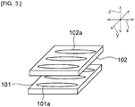
- Fig. 3 is a schematic perspective view for illustrating how to overlay green sheets one upon another in a method for manufacturing a wavelength conversion member according to a comparative example.
- first and second green sheets 101, 102 are overlaid one upon another so that the respective directions of movement of the doctor blade in the step of forming the green sheet are the same direction x.
- stripes 101a, 102a as shown in Fig. 3 tend to form along the direction of movement of the doctor blade (the direction of formation of a green sheet) .
- the stripes 101a, 102a are portions formed linearly in the direction of movement of the doctor blade and having a relatively high (or low) phosphor concentration.
- the stripes 101a on the first green sheet 101 and the stripes 102a on the second green sheet 102 are oriented substantially in the same direction in plan view.
- the phosphor concentration in the portions provided with the stripes 101a, 102a becomes even higher (or smaller) as compared to that in the surrounding portions. Therefore, a wavelength conversion member obtained by the manufacturing method according to the comparative example is likely to have unevenness in luminescent color.
- the first and second green sheets 4, 5 are overlaid one upon another so that the direction of movement of the doctor blade for the first green sheet 4 and the direction of movement of the doctor blade for the second green sheet 5 intersect each other. More specifically, as shown in Fig. 2 , the overlaying is performed so that the direction of movement of the doctor blade for the first green sheet 4 is the direction x. At the same time, the overlaying is performed so that the direction of movement of the doctor blade for the second green sheet 5 is the direction y. Thus, stripes 4a on the first green sheet 4 and stripes 5a on the second green sheet 5 are overlapped to intersect one another in plan view. Therefore, a wavelength conversion member 1 obtained by the manufacturing method according to this embodiment is less likely to have unevenness in luminescent color.
- a green sheet laminate is formed in such a manner that, as described above, in overlaying a plurality of green sheets one upon another, as for at least two of the plurality of green sheets, these green sheets are overlaid so that the respective directions of movement of the doctor blade in the step of forming the green sheet intersect each other.
- a green sheet laminate may be formed by repeatedly and alternately overlaying two types of green sheets having different directions of movement of the doctor blade in the step of forming the green sheet. By doing so, the unevenness in luminescent color can be further prevented.
- these green sheets are preferably overlaid so that the direction y of movement of the doctor blade for the second green sheet 5 is substantially perpendicular to the direction x of movement of the doctor blade for the first green sheet 4.
Landscapes
- Chemical & Material Sciences (AREA)
- Engineering & Computer Science (AREA)
- Materials Engineering (AREA)
- Organic Chemistry (AREA)
- Manufacturing & Machinery (AREA)
- Ceramic Engineering (AREA)
- Physics & Mathematics (AREA)
- Dispersion Chemistry (AREA)
- Inorganic Chemistry (AREA)
- Geochemistry & Mineralogy (AREA)
- General Chemical & Material Sciences (AREA)
- Chemical Kinetics & Catalysis (AREA)
- Life Sciences & Earth Sciences (AREA)
- General Physics & Mathematics (AREA)
- Optics & Photonics (AREA)
- Structural Engineering (AREA)
- Crystallography & Structural Chemistry (AREA)
- Mechanical Engineering (AREA)
- Led Device Packages (AREA)
- Optical Filters (AREA)
- Luminescent Compositions (AREA)
Abstract
Description
- The present invention relates to methods for manufacturing wavelength conversion members that convert the wavelength of light emitted from a light emitting diode (LED), a laser diode (LD) or the like to another wavelength.
- Recently, attention has been increasingly focused on light emitting devices and the like using LEDs or LDs, as next-generation light sources to replace fluorescence lamps and incandescent lamps. As an example of such a next-generation light source, there is a disclosure of a light emitting device in which an LED for emitting a blue light is combined with a wavelength conversion member capable of absorbing part of the light from the LED to convert it to a yellow light. This light emitting device emits a white light which is a synthesized light of the blue light emitted from the LED and the yellow light emitted from the wavelength conversion member. Patent Literature 1 proposes, as an example of a wavelength conversion member, a wavelength conversion member in which phosphor particles are dispersed in a glass matrix.
-
Patent Literature 2 discloses, as a method for manufacturing a wavelength conversion member having a large size and a small and uniform thickness, a manufacturing method based on the green sheet method. -
- [PTL 1]
JP-A-2003-258308 - [PTL 2]
JP-A-2007-182529 - In such a manufacturing method based on the green sheet method as described above, obtained wavelength conversion members often have unevenness in luminescent color.
- An object of the present invention is to provide a method for manufacturing a wavelength conversion member by which unevenness in luminescent color are less likely to occur.
- A method for manufacturing a wavelength conversion member according to the present invention is a method for manufacturing a wavelength conversion member including phosphor particles disposed in a glass matrix and includes the steps of: preparing a slurry containing glass particles to be the glass matrix and the phosphor particles; forming a green sheet by applying the slurry onto a support substrate and moving a doctor blade relative to the slurry, the doctor blade being spaced a predetermined distance away from the support substrate; forming a green sheet laminate by applying heat and pressure to a plurality of the green sheets overlaid one upon another; and sintering the green sheet laminate to obtain a wavelength conversion member, wherein in the step of forming a green sheet laminate, the plurality of green sheets are overlaid one upon another so that, as for at least two of the plurality of green sheets, respective directions of movement of the doctor blade in the step of forming a green sheet intersect each other.
- In the method for manufacturing a wavelength conversion member according to the present invention, preferably, the step of forming a green sheet laminate is the step of repeatedly and alternately overlaying first and second green sheets one upon another to form the green sheet laminate, and in overlaying the first and second green sheets one upon another, the first and second green sheets are overlaid one upon another so that the respective directions of movement of the doctor blade in the step of forming each of the first and second green sheets intersect each other.
- In the method for manufacturing a wavelength conversion member according to the present invention, preferably, in overlaying the first and second green sheets one upon another, the first and second green sheets are overlaid one upon another so that the respective directions of movement of the doctor blade in the step of forming each of the first and second green sheets are substantially perpendicular to each other.
- In the method for manufacturing a wavelength conversion member according to the present invention, preferably, in overlaying the green sheets one upon another, three or more green sheets are overlaid one upon another.
- The present invention enables provision of a method for manufacturing a wavelength conversion member by which unevenness in luminescent color are less likely to occur.
-
-
Fig. 1 is a schematic cross-sectional view showing a wavelength conversion member manufactured by a method for manufacturing a wavelength conversion member according to one embodiment of the present invention. -
Fig. 2 is a schematic perspective view for illustrating how to overlay green sheets one upon another in the method for manufacturing a wavelength conversion member according to the one embodiment of the present invention. -
Fig. 3 is a schematic perspective view for illustrating how to overlay green sheets one upon another in a method for manufacturing a wavelength conversion member according to a comparative example. - Hereinafter, a description will be given of a preferred embodiment. However, the following embodiment is merely illustrative and the present invention is not limited to the following embodiment. Throughout the drawings, members having substantially the same functions may be referred to by the same reference characters.
-
Fig. 1 is a schematic cross-sectional view showing a wavelength conversion member manufactured by a method for manufacturing a wavelength conversion member according to one embodiment of the present invention. As shown inFig. 1 , a wavelength conversion member 1 is made of a phosphor glass that contains aglass matrix 2 andphosphor particles 3. Thephosphor particles 3 are disposed in theglass matrix 2. More specifically, thephosphor particles 3 are dispersed in theglass matrix 2. The wavelength conversion member 1 has, for example, a rectangular plate shape. - In the wavelength conversion member 1 according to this embodiment, for example, excitation light enters the wavelength conversion member 1 through one principal surface thereof, and a synthesized light of the excitation light and fluorescence emitted from the
phosphor particles 3 exits the wavelength conversion member 1 through the other principal surface thereof. - No particular limitation is placed on the type of glass forming the
glass matrix 2 so long as it can be used as a dispersion medium for thephosphor particles 3, such as inorganic phosphor. For example, borosilicate glass, phosphate glass, tin-phosphate glass or bismuthate glass can be used. Examples of the borosilicate glass include those containing, in % by mass, 30 to 85% SiO2, 0 to 30% Al2O3, 0 to 50% B2O3, 0 to 10% Li2O+Na2O+K2O, and 0 to 50% MgO+CaO+SrO+BaO. Examples of the tin-phosphate glass include those containing, in % by mole, 30 to 90% SnO and 1 to 70% P2O5. - The softening point of the
glass matrix 2 is preferably 250°C to 1000°C, more preferably 300°C to 950°C, and still more preferably in a range of 500°C to 900°C. If the softening point of theglass matrix 2 is too low, the mechanical strength and chemical durability of the wavelength conversion member 1 may decrease. Furthermore, because the thermal resistance of theglass matrix 2 itself is low, the wavelength conversion member 1 may be softened and deformed by heat generated by thephosphor particles 3. On the other hand, if the softening point of theglass matrix 2 is too high, thephosphor particles 3 may be deteriorated in the step of sintering a green sheet laminate, so that the luminescence intensity of the wavelength conversion member 1 may decrease. From the viewpoint of further increasing the chemical stability and mechanical strength of the wavelength conversion member 1, the softening point of theglass matrix 2 is preferably not less than 500°C, more preferably not less than 600°C, still more preferably not less than 700°C, yet still more preferably not less than 800°C, and particularly preferably not less than 850°C. An example of such a glass is borosilicate glass. However, if the softening point of theglass matrix 2 rises, the firing temperature also rises and, as a result, the production cost tends to rise. Therefore, from the viewpoint of more inexpensively manufacturing the wavelength conversion member 1, the softening point of theglass matrix 2 is preferably not more than 550°C, more preferably not more than 530°C, still more preferably not more than 500°C, yet still more preferably not more than 480°C, and particularly preferably not more than 460°C. Examples of such a glass include tin-phosphate glass and bismuthate glass. - No particular limitation is placed on the type of the
phosphor particles 3 so long as they emit fluorescence upon entry of excitation light. A specific example of the type of thephosphor particles 3 is one or more selected from the group consisting of oxide phosphor, nitride phosphor, oxynitride phosphor, chloride phosphor, oxychloride phosphor, sulfide phosphor, oxysulfide phosphor, halide phosphor, chalcogenide phosphor, aluminate phosphor, halophosphoric acid chloride phosphor, and garnet-based compound phosphor. When using a blue light as the excitation light, for example, a phosphor emitting a green light, a yellow light or a red light as fluorescence can be used. - The average particle diameter of the
phosphor particles 3 is preferably 1 µm to 50 µm and more preferably 5 µm to 25 µm. If the average particle diameter of thephosphor particles 3 is too small, the luminescence intensity may decrease. On the other hand, if the average particle diameter of thephosphor particles 3 is too large, the luminescent color may be uneven. - The content of
phosphor particles 3 in the wavelength conversion member 1 is preferably not less than 1% by volume, more preferably not less than 1.5% by volume, particularly preferably not less than 2% by volume, preferably not more than 70% by volume, more preferably not more than 50% by volume, and particularly preferably not more than 30% by volume. If the content ofphosphor particles 3 is too small, the luminescence intensity may decrease. On the other hand, if the content ofphosphor particles 3 is too large, the luminescent color may be uneven. - The thickness of the wavelength conversion member 1 is preferably not less than 0.01 mm, more preferably not less than 0.03 mm, still more preferably not less than 0.05 mm, yet still more preferably not less than 0.075 mm, and particularly preferably not less than 0.1 mm, preferably not more than 1 mm, more preferably not more than 0.5 mm, still more preferably not more than 0.35 mm, yet still more preferably not more than 0.3 mm, and particularly preferably not more than 0.25 mm. If the thickness of the wavelength conversion member 1 is too large, scattering and absorption of light in the wavelength conversion member 1 may become too much, so that the efficiency of emission of fluorescence may become low. If the thickness of the wavelength conversion member 1 is too small, sufficient luminescence intensity may be less likely to be obtained. In addition, the mechanical strength of the wavelength conversion member 1 may be insufficient.
- A description will be given below of an example of a method for manufacturing a wavelength conversion member 1.
- In the method for manufacturing the wavelength conversion member 1, first, a slurry is prepared which contains glass particles to be a
glass matrix 2 andphosphor particles 3. The slurry normally contains a binder resin and a solvent. - Subsequently, the prepared slurry is applied onto a support substrate and a doctor blade spaced a predetermined distance away from the support substrate is moved relative to the slurry to form a green sheet. The formed green sheet is cut into a plurality of green sheets. For example, a resin film made of polyethylene terephthalate or other resins can be used as the support substrate.
- Next, heat and pressure are applied to the plurality of prepared green sheets overlaid one upon another to form a green sheet laminate. In the manufacturing method according to this embodiment, the plurality of green sheets are overlaid one upon another so that, as for at least two of the plurality of green sheets, the respective directions of movement of the doctor blade (the directions of formation of the green sheets) in the step of forming the green sheet intersect each other.
- No particular limitation is placed on the temperature during the application of heat and pressure, but it is preferably not less than 30°C, more preferably not less than 60°C, preferably not more than 170°C, and more preferably not more than 140°C. If the temperature during the application of heat and pressure is too low, glass transition of the binder resin may not occur sufficiently, so that an adhesion failure may occur between the green sheets. If the temperature during the application of heat and pressure is too high, the fluidity of the green sheets may become too high, so that the green sheets may be deformed.
- No particular limitation is placed on the pressure during the application of heat and pressure, but it is preferably not less than 0.1 MPa, more preferably not less than 1 MPa, preferably not more than 60 MPa, and more preferably not more than 30 MPa. If the pressure during the application of heat and pressure is too low, the adhesion between the green sheets may become weak, so that a delamination may occur after sintering. If the pressure during the application of heat and pressure is too high, the green sheet may be deformed.
- Furthermore, in overlaying the plurality of green sheets one upon another, three or more green sheets are preferably overlaid one upon another. In this case, the obtained wavelength conversion member 1 is even less likely to have unevenness in luminescent color. In addition, the mechanical strength of the obtained wavelength conversion member 1 can be further increased. No particular limitation is placed on the upper limit of the number of green sheets overlaid, but it is generally not more than ten and preferably not more than six.
- Next, the green sheet laminate is sintered. Thus, a wavelength conversion member 1 can be obtained. The sintering temperature for the green sheet laminate is, for example, preferably in a range of the softening point of the glass particles to the softening point of the glass particles plus about 100°C. If the sintering temperature for the green sheet laminate is too low, a dense sintered body becomes less likely to be obtained, so that the wavelength conversion member 1 tends to have poor mechanical strength. On the other hand, if the sintering temperature for the green sheet laminate is too high, the
phosphor particles 3, if having low thermal resistance, may be thermally deteriorated, so that the luminescence intensity may decrease. - As described previously, in the manufacturing method according to this embodiment, in overlaying a plurality of green sheets one upon another, the plurality of green sheets are overlaid one upon another so that, as for at least two of the plurality of green sheets, the respective directions of movement of the doctor blade in the step of forming the green sheet intersect each other. Therefore, the obtained wavelength conversion member 1 can be made less likely to have unevenness in luminescent color. This will be described below in more detail with reference to
Figs. 2 and3 . -
Fig. 2 is a schematic perspective view for illustrating how to overlay green sheets one upon another in the method for manufacturing a wavelength conversion member according to the one embodiment of the present invention. Furthermore,Fig. 3 is a schematic perspective view for illustrating how to overlay green sheets one upon another in a method for manufacturing a wavelength conversion member according to a comparative example. - As shown in
Fig. 3 , in a manufacturing method according to a comparative example, first and secondgreen sheets - In a method for forming a green sheet based on the doctor blade method,
such stripes Fig. 3 tend to form along the direction of movement of the doctor blade (the direction of formation of a green sheet) . Thestripes Fig. 3 , in the manufacturing method according to the comparative example, thestripes 101a on the firstgreen sheet 101 and thestripes 102a on the secondgreen sheet 102 are oriented substantially in the same direction in plan view. Thus, the phosphor concentration in the portions provided with thestripes - Unlike the above, in the manufacturing method according to this embodiment, the first and second
green sheets green sheet 4 and the direction of movement of the doctor blade for the secondgreen sheet 5 intersect each other. More specifically, as shown inFig. 2 , the overlaying is performed so that the direction of movement of the doctor blade for the firstgreen sheet 4 is the direction x. At the same time, the overlaying is performed so that the direction of movement of the doctor blade for the secondgreen sheet 5 is the direction y. Thus,stripes 4a on the firstgreen sheet 4 andstripes 5a on the secondgreen sheet 5 are overlapped to intersect one another in plan view. Therefore, a wavelength conversion member 1 obtained by the manufacturing method according to this embodiment is less likely to have unevenness in luminescent color. - In the manufacturing method according to this embodiment, a green sheet laminate is formed in such a manner that, as described above, in overlaying a plurality of green sheets one upon another, as for at least two of the plurality of green sheets, these green sheets are overlaid so that the respective directions of movement of the doctor blade in the step of forming the green sheet intersect each other.
- However, in the present invention, like the first and second
green sheets Fig. 2 , a green sheet laminate may be formed by repeatedly and alternately overlaying two types of green sheets having different directions of movement of the doctor blade in the step of forming the green sheet. By doing so, the unevenness in luminescent color can be further prevented. - Furthermore, in overlaying the first and second
green sheets green sheet 5 is substantially perpendicular to the direction x of movement of the doctor blade for the firstgreen sheet 4. By overlaying them one upon another in this manner, the unevenness in luminescent color can be still further prevented. -
- 1
- wavelength conversion member
- 2
- glass matrix
- 3
- phosphor particle
- 4, 5
- first and second green sheets
- 4a, 5a
- stripe
Claims (4)
- A method for manufacturing a wavelength conversion member including phosphor particles disposed in a glass matrix, the method comprising the steps of:preparing a slurry containing glass particles to be the glass matrix and the phosphor particles;forming a green sheet by applying the slurry onto a support substrate and moving a doctor blade relative to the slurry, the doctor blade being spaced a predetermined distance away from the support substrate;forming a green sheet laminate by applying heat and pressure to a plurality of the green sheets overlaid one upon another; andsintering the green sheet laminate to obtain a wavelength conversion member,wherein in the step of forming a green sheet laminate, the plurality of green sheets are overlaid one upon another so that, as for at least two of the plurality of green sheets, respective directions of movement of the doctor blade in the step of forming a green sheet intersect each other.
- The method for manufacturing a wavelength conversion member according to claim 1, wherein
the step of forming a green sheet laminate is the step of repeatedly and alternately overlaying first and second green sheets one upon another to form the green sheet laminate, and
in overlaying the first and second green sheets one upon another, the first and second green sheets are overlaid one upon another so that the respective directions of movement of the doctor blade in the step of forming each of the first and second green sheets intersect each other. - The method for manufacturing a wavelength conversion member according to claim 2, wherein in overlaying the first and second green sheets one upon another, the first and second green sheets are overlaid one upon another so that the respective directions of movement of the doctor blade in the step of forming each of the first and second green sheets are substantially perpendicular to each other.
- The method for manufacturing a wavelength conversion member according to any one of claims 1 to 3, wherein in overlaying the green sheets one upon another, three or more green sheets are overlaid one upon another.
Applications Claiming Priority (2)
| Application Number | Priority Date | Filing Date | Title |
|---|---|---|---|
| JP2016162413A JP6885689B2 (en) | 2016-08-23 | 2016-08-23 | Manufacturing method of wavelength conversion member |
| PCT/JP2017/027966 WO2018037856A1 (en) | 2016-08-23 | 2017-08-02 | Method for manufacturing wavelength conversion member |
Publications (3)
| Publication Number | Publication Date |
|---|---|
| EP3508890A1 true EP3508890A1 (en) | 2019-07-10 |
| EP3508890A4 EP3508890A4 (en) | 2020-04-22 |
| EP3508890B1 EP3508890B1 (en) | 2023-04-19 |
Family
ID=61245776
Family Applications (1)
| Application Number | Title | Priority Date | Filing Date |
|---|---|---|---|
| EP17843342.1A Active EP3508890B1 (en) | 2016-08-23 | 2017-08-02 | Method for manufacturing wavelength conversion member |
Country Status (6)
| Country | Link |
|---|---|
| US (1) | US20190241456A1 (en) |
| EP (1) | EP3508890B1 (en) |
| JP (1) | JP6885689B2 (en) |
| KR (1) | KR102362017B1 (en) |
| CN (1) | CN109642969A (en) |
| WO (1) | WO2018037856A1 (en) |
Families Citing this family (5)
| Publication number | Priority date | Publication date | Assignee | Title |
|---|---|---|---|---|
| WO2016138005A1 (en) | 2015-02-27 | 2016-09-01 | Schlumberger Technology Corporation | Vertical drilling and fracturing methodology |
| DE102019202785B4 (en) * | 2018-03-02 | 2024-01-18 | Coorstek Kk | Glass element |
| KR102149988B1 (en) * | 2018-09-07 | 2020-08-31 | 대주전자재료 주식회사 | Laminated body for preparing wavelength conversion member and preparation method of wavelength conversion member |
| KR102512806B1 (en) | 2020-09-09 | 2023-03-23 | 대주전자재료 주식회사 | Light emitting device and preparation method thereof |
| KR102576253B1 (en) * | 2021-05-11 | 2023-09-11 | 대주전자재료 주식회사 | Wavelength conversion member and light emitting device comprising same |
Family Cites Families (20)
| Publication number | Priority date | Publication date | Assignee | Title |
|---|---|---|---|---|
| JPS57136396A (en) * | 1981-02-18 | 1982-08-23 | Hitachi Ltd | Method of producing multilayer ceramic substrate |
| JP2943129B2 (en) * | 1992-12-29 | 1999-08-30 | インターナショナル・ビジネス・マシーンズ・コーポレーション | Ceramic composition, ceramic green sheet and manufacturing method |
| JP4158012B2 (en) | 2002-03-06 | 2008-10-01 | 日本電気硝子株式会社 | Luminescent color conversion member |
| JP2007182529A (en) * | 2005-05-11 | 2007-07-19 | Nippon Electric Glass Co Ltd | Fluorescent composite glass, fluorescent composite glass green sheet and process for production of fluorescent composite glass |
| CN101171205A (en) * | 2005-05-11 | 2008-04-30 | 日本电气硝子株式会社 | Phosphor composite glass, phosphor composite glass green sheet, and method for manufacturing phosphor composite glass |
| JP4788410B2 (en) * | 2006-03-09 | 2011-10-05 | 株式会社デンソー | Manufacturing method of ceramic laminated substrate |
| JP4978886B2 (en) * | 2006-06-14 | 2012-07-18 | 日本電気硝子株式会社 | Phosphor composite material and phosphor composite member |
| JP2008016587A (en) * | 2006-07-05 | 2008-01-24 | Denso Corp | Manufacturing method of ceramic laminated substrate |
| JP2011175102A (en) * | 2010-02-24 | 2011-09-08 | Sony Corp | Optical sheet stack body, illuminating device and display device |
| CN102782082A (en) * | 2010-07-14 | 2012-11-14 | 日本电气硝子株式会社 | Phosphor composite part, LED device, and method for manufacturing phosphor composite part |
| WO2013058065A1 (en) * | 2011-10-18 | 2013-04-25 | 株式会社村田製作所 | Light-emitting element, method for producing same, and light-emitting device |
| JP6063126B2 (en) | 2012-01-10 | 2017-01-18 | 日本電気硝子株式会社 | Wavelength conversion member, light emitting device, and method of manufacturing wavelength conversion member |
| JP6069890B2 (en) * | 2012-05-29 | 2017-02-01 | 日亜化学工業株式会社 | Inorganic molded body for wavelength conversion and light emitting device |
| JP6065567B2 (en) | 2012-12-13 | 2017-01-25 | 日本電気硝子株式会社 | Color wheel for projector and light emitting device for projector |
| JP2013138216A (en) * | 2013-01-30 | 2013-07-11 | Nitto Denko Corp | Light-emitting device |
| JP6503710B2 (en) * | 2013-12-27 | 2019-04-24 | 日本電気硝子株式会社 | Fluorescent wheel for projector, method of manufacturing the same, and light emitting device for projector |
| JP2015142046A (en) * | 2014-01-29 | 2015-08-03 | シャープ株式会社 | Wavelength conversion member, light emitting device, and method of manufacturing wavelength conversion member |
| JP6252982B2 (en) * | 2014-02-06 | 2017-12-27 | 日本電気硝子株式会社 | Glass member and manufacturing method thereof |
| WO2016063930A1 (en) * | 2014-10-24 | 2016-04-28 | デンカ株式会社 | Wavelength converter, light-emitting device using same, and production method for wavelength converter |
| JP6471488B2 (en) * | 2014-12-17 | 2019-02-20 | 日本電気硝子株式会社 | Wavelength conversion member and light emitting device |
-
2016
- 2016-08-23 JP JP2016162413A patent/JP6885689B2/en active Active
-
2017
- 2017-08-02 WO PCT/JP2017/027966 patent/WO2018037856A1/en not_active Ceased
- 2017-08-02 EP EP17843342.1A patent/EP3508890B1/en active Active
- 2017-08-02 KR KR1020187034375A patent/KR102362017B1/en active Active
- 2017-08-02 CN CN201780050654.7A patent/CN109642969A/en active Pending
- 2017-08-02 US US16/315,701 patent/US20190241456A1/en not_active Abandoned
Also Published As
| Publication number | Publication date |
|---|---|
| US20190241456A1 (en) | 2019-08-08 |
| CN109642969A (en) | 2019-04-16 |
| EP3508890B1 (en) | 2023-04-19 |
| JP2018031829A (en) | 2018-03-01 |
| JP6885689B2 (en) | 2021-06-16 |
| KR102362017B1 (en) | 2022-02-10 |
| EP3508890A4 (en) | 2020-04-22 |
| KR20190039882A (en) | 2019-04-16 |
| WO2018037856A1 (en) | 2018-03-01 |
Similar Documents
| Publication | Publication Date | Title |
|---|---|---|
| EP3508890B1 (en) | Method for manufacturing wavelength conversion member | |
| US11322659B2 (en) | Method for manufacturing wavelength conversion member, wavelength conversion member, and light-emitting device | |
| EP3495722B1 (en) | Wavelength conversion member and production method therefor | |
| JP2018077324A (en) | Wavelength conversion member and light emitting device | |
| US8993367B2 (en) | Method for producing cell for light-emitting device and method for producing light-emitting device | |
| EP3495857B1 (en) | Wavelength conversion member and production method therefor | |
| EP3495721B1 (en) | Wavelength conversion member and production method therefor | |
| US11975519B2 (en) | Method of manufacturing plate-like member and laminate | |
| JP2021067797A (en) | Method for manufacturing tabular member, tabular member intermediate and tabular member | |
| JP2018049185A (en) | Wavelength conversion member and light-emitting device | |
| JP2019028096A (en) | Wavelength conversion member | |
| JP2018013681A (en) | Wavelength conversion member and light emitting device |
Legal Events
| Date | Code | Title | Description |
|---|---|---|---|
| STAA | Information on the status of an ep patent application or granted ep patent |
Free format text: STATUS: THE INTERNATIONAL PUBLICATION HAS BEEN MADE |
|
| PUAI | Public reference made under article 153(3) epc to a published international application that has entered the european phase |
Free format text: ORIGINAL CODE: 0009012 |
|
| STAA | Information on the status of an ep patent application or granted ep patent |
Free format text: STATUS: REQUEST FOR EXAMINATION WAS MADE |
|
| 17P | Request for examination filed |
Effective date: 20190109 |
|
| AK | Designated contracting states |
Kind code of ref document: A1 Designated state(s): AL AT BE BG CH CY CZ DE DK EE ES FI FR GB GR HR HU IE IS IT LI LT LU LV MC MK MT NL NO PL PT RO RS SE SI SK SM TR |
|
| AX | Request for extension of the european patent |
Extension state: BA ME |
|
| DAV | Request for validation of the european patent (deleted) | ||
| DAX | Request for extension of the european patent (deleted) | ||
| A4 | Supplementary search report drawn up and despatched |
Effective date: 20200324 |
|
| RIC1 | Information provided on ipc code assigned before grant |
Ipc: G02B 5/20 20060101ALI20200318BHEP Ipc: H01L 33/50 20100101ALI20200318BHEP Ipc: B32B 17/10 20060101ALI20200318BHEP Ipc: B32B 17/00 20060101ALI20200318BHEP Ipc: C03C 3/16 20060101ALI20200318BHEP Ipc: C03B 19/06 20060101ALI20200318BHEP Ipc: C03C 14/00 20060101AFI20200318BHEP Ipc: C03C 8/14 20060101ALI20200318BHEP Ipc: C09K 11/08 20060101ALI20200318BHEP |
|
| REG | Reference to a national code |
Ref country code: DE Ref legal event code: R079 Ref document number: 602017067908 Country of ref document: DE Free format text: PREVIOUS MAIN CLASS: G02B0005200000 Ipc: C03C0014000000 Ref country code: DE Ref legal event code: R079 Free format text: PREVIOUS MAIN CLASS: G02B0005200000 Ipc: C03C0014000000 |
|
| RIC1 | Information provided on ipc code assigned before grant |
Ipc: C09K 11/02 20060101ALI20220714BHEP Ipc: C09K 11/08 20060101ALI20220714BHEP Ipc: C03C 3/16 20060101ALI20220714BHEP Ipc: H01L 33/50 20100101ALI20220714BHEP Ipc: G02B 5/20 20060101ALI20220714BHEP Ipc: C03B 19/06 20060101ALI20220714BHEP Ipc: C03C 8/14 20060101ALI20220714BHEP Ipc: C03C 14/00 20060101AFI20220714BHEP |
|
| GRAP | Despatch of communication of intention to grant a patent |
Free format text: ORIGINAL CODE: EPIDOSNIGR1 |
|
| STAA | Information on the status of an ep patent application or granted ep patent |
Free format text: STATUS: GRANT OF PATENT IS INTENDED |
|
| INTG | Intention to grant announced |
Effective date: 20220913 |
|
| GRAJ | Information related to disapproval of communication of intention to grant by the applicant or resumption of examination proceedings by the epo deleted |
Free format text: ORIGINAL CODE: EPIDOSDIGR1 |
|
| STAA | Information on the status of an ep patent application or granted ep patent |
Free format text: STATUS: REQUEST FOR EXAMINATION WAS MADE |
|
| INTC | Intention to grant announced (deleted) | ||
| GRAP | Despatch of communication of intention to grant a patent |
Free format text: ORIGINAL CODE: EPIDOSNIGR1 |
|
| STAA | Information on the status of an ep patent application or granted ep patent |
Free format text: STATUS: GRANT OF PATENT IS INTENDED |
|
| GRAS | Grant fee paid |
Free format text: ORIGINAL CODE: EPIDOSNIGR3 |
|
| GRAA | (expected) grant |
Free format text: ORIGINAL CODE: 0009210 |
|
| STAA | Information on the status of an ep patent application or granted ep patent |
Free format text: STATUS: THE PATENT HAS BEEN GRANTED |
|
| INTG | Intention to grant announced |
Effective date: 20230309 |
|
| AK | Designated contracting states |
Kind code of ref document: B1 Designated state(s): AL AT BE BG CH CY CZ DE DK EE ES FI FR GB GR HR HU IE IS IT LI LT LU LV MC MK MT NL NO PL PT RO RS SE SI SK SM TR |
|
| REG | Reference to a national code |
Ref country code: GB Ref legal event code: FG4D |
|
| REG | Reference to a national code |
Ref country code: DE Ref legal event code: R096 Ref document number: 602017067908 Country of ref document: DE |
|
| REG | Reference to a national code |
Ref country code: CH Ref legal event code: EP |
|
| REG | Reference to a national code |
Ref country code: IE Ref legal event code: FG4D |
|
| REG | Reference to a national code |
Ref country code: AT Ref legal event code: REF Ref document number: 1561077 Country of ref document: AT Kind code of ref document: T Effective date: 20230515 |
|
| REG | Reference to a national code |
Ref country code: LT Ref legal event code: MG9D |
|
| REG | Reference to a national code |
Ref country code: NL Ref legal event code: MP Effective date: 20230419 |
|
| REG | Reference to a national code |
Ref country code: AT Ref legal event code: MK05 Ref document number: 1561077 Country of ref document: AT Kind code of ref document: T Effective date: 20230419 |
|
| PG25 | Lapsed in a contracting state [announced via postgrant information from national office to epo] |
Ref country code: NL Free format text: LAPSE BECAUSE OF FAILURE TO SUBMIT A TRANSLATION OF THE DESCRIPTION OR TO PAY THE FEE WITHIN THE PRESCRIBED TIME-LIMIT Effective date: 20230419 |
|
| PG25 | Lapsed in a contracting state [announced via postgrant information from national office to epo] |
Ref country code: SE Free format text: LAPSE BECAUSE OF FAILURE TO SUBMIT A TRANSLATION OF THE DESCRIPTION OR TO PAY THE FEE WITHIN THE PRESCRIBED TIME-LIMIT Effective date: 20230419 Ref country code: PT Free format text: LAPSE BECAUSE OF FAILURE TO SUBMIT A TRANSLATION OF THE DESCRIPTION OR TO PAY THE FEE WITHIN THE PRESCRIBED TIME-LIMIT Effective date: 20230821 Ref country code: NO Free format text: LAPSE BECAUSE OF FAILURE TO SUBMIT A TRANSLATION OF THE DESCRIPTION OR TO PAY THE FEE WITHIN THE PRESCRIBED TIME-LIMIT Effective date: 20230719 Ref country code: ES Free format text: LAPSE BECAUSE OF FAILURE TO SUBMIT A TRANSLATION OF THE DESCRIPTION OR TO PAY THE FEE WITHIN THE PRESCRIBED TIME-LIMIT Effective date: 20230419 Ref country code: AT Free format text: LAPSE BECAUSE OF FAILURE TO SUBMIT A TRANSLATION OF THE DESCRIPTION OR TO PAY THE FEE WITHIN THE PRESCRIBED TIME-LIMIT Effective date: 20230419 |
|
| PG25 | Lapsed in a contracting state [announced via postgrant information from national office to epo] |
Ref country code: RS Free format text: LAPSE BECAUSE OF FAILURE TO SUBMIT A TRANSLATION OF THE DESCRIPTION OR TO PAY THE FEE WITHIN THE PRESCRIBED TIME-LIMIT Effective date: 20230419 Ref country code: PL Free format text: LAPSE BECAUSE OF FAILURE TO SUBMIT A TRANSLATION OF THE DESCRIPTION OR TO PAY THE FEE WITHIN THE PRESCRIBED TIME-LIMIT Effective date: 20230419 Ref country code: LV Free format text: LAPSE BECAUSE OF FAILURE TO SUBMIT A TRANSLATION OF THE DESCRIPTION OR TO PAY THE FEE WITHIN THE PRESCRIBED TIME-LIMIT Effective date: 20230419 Ref country code: LT Free format text: LAPSE BECAUSE OF FAILURE TO SUBMIT A TRANSLATION OF THE DESCRIPTION OR TO PAY THE FEE WITHIN THE PRESCRIBED TIME-LIMIT Effective date: 20230419 Ref country code: IS Free format text: LAPSE BECAUSE OF FAILURE TO SUBMIT A TRANSLATION OF THE DESCRIPTION OR TO PAY THE FEE WITHIN THE PRESCRIBED TIME-LIMIT Effective date: 20230819 Ref country code: HR Free format text: LAPSE BECAUSE OF FAILURE TO SUBMIT A TRANSLATION OF THE DESCRIPTION OR TO PAY THE FEE WITHIN THE PRESCRIBED TIME-LIMIT Effective date: 20230419 Ref country code: GR Free format text: LAPSE BECAUSE OF FAILURE TO SUBMIT A TRANSLATION OF THE DESCRIPTION OR TO PAY THE FEE WITHIN THE PRESCRIBED TIME-LIMIT Effective date: 20230720 Ref country code: AL Free format text: LAPSE BECAUSE OF FAILURE TO SUBMIT A TRANSLATION OF THE DESCRIPTION OR TO PAY THE FEE WITHIN THE PRESCRIBED TIME-LIMIT Effective date: 20230419 |
|
| PG25 | Lapsed in a contracting state [announced via postgrant information from national office to epo] |
Ref country code: FI Free format text: LAPSE BECAUSE OF FAILURE TO SUBMIT A TRANSLATION OF THE DESCRIPTION OR TO PAY THE FEE WITHIN THE PRESCRIBED TIME-LIMIT Effective date: 20230419 |
|
| PG25 | Lapsed in a contracting state [announced via postgrant information from national office to epo] |
Ref country code: SK Free format text: LAPSE BECAUSE OF FAILURE TO SUBMIT A TRANSLATION OF THE DESCRIPTION OR TO PAY THE FEE WITHIN THE PRESCRIBED TIME-LIMIT Effective date: 20230419 |
|
| REG | Reference to a national code |
Ref country code: DE Ref legal event code: R097 Ref document number: 602017067908 Country of ref document: DE |
|
| PG25 | Lapsed in a contracting state [announced via postgrant information from national office to epo] |
Ref country code: SM Free format text: LAPSE BECAUSE OF FAILURE TO SUBMIT A TRANSLATION OF THE DESCRIPTION OR TO PAY THE FEE WITHIN THE PRESCRIBED TIME-LIMIT Effective date: 20230419 Ref country code: SK Free format text: LAPSE BECAUSE OF FAILURE TO SUBMIT A TRANSLATION OF THE DESCRIPTION OR TO PAY THE FEE WITHIN THE PRESCRIBED TIME-LIMIT Effective date: 20230419 Ref country code: RO Free format text: LAPSE BECAUSE OF FAILURE TO SUBMIT A TRANSLATION OF THE DESCRIPTION OR TO PAY THE FEE WITHIN THE PRESCRIBED TIME-LIMIT Effective date: 20230419 Ref country code: EE Free format text: LAPSE BECAUSE OF FAILURE TO SUBMIT A TRANSLATION OF THE DESCRIPTION OR TO PAY THE FEE WITHIN THE PRESCRIBED TIME-LIMIT Effective date: 20230419 Ref country code: DK Free format text: LAPSE BECAUSE OF FAILURE TO SUBMIT A TRANSLATION OF THE DESCRIPTION OR TO PAY THE FEE WITHIN THE PRESCRIBED TIME-LIMIT Effective date: 20230419 Ref country code: CZ Free format text: LAPSE BECAUSE OF FAILURE TO SUBMIT A TRANSLATION OF THE DESCRIPTION OR TO PAY THE FEE WITHIN THE PRESCRIBED TIME-LIMIT Effective date: 20230419 |
|
| PLBE | No opposition filed within time limit |
Free format text: ORIGINAL CODE: 0009261 |
|
| STAA | Information on the status of an ep patent application or granted ep patent |
Free format text: STATUS: NO OPPOSITION FILED WITHIN TIME LIMIT |
|
| PG25 | Lapsed in a contracting state [announced via postgrant information from national office to epo] |
Ref country code: MC Free format text: LAPSE BECAUSE OF FAILURE TO SUBMIT A TRANSLATION OF THE DESCRIPTION OR TO PAY THE FEE WITHIN THE PRESCRIBED TIME-LIMIT Effective date: 20230419 |
|
| 26N | No opposition filed |
Effective date: 20240122 |
|
| REG | Reference to a national code |
Ref country code: CH Ref legal event code: PL |
|
| PG25 | Lapsed in a contracting state [announced via postgrant information from national office to epo] |
Ref country code: MC Free format text: LAPSE BECAUSE OF FAILURE TO SUBMIT A TRANSLATION OF THE DESCRIPTION OR TO PAY THE FEE WITHIN THE PRESCRIBED TIME-LIMIT Effective date: 20230419 |
|
| PG25 | Lapsed in a contracting state [announced via postgrant information from national office to epo] |
Ref country code: LU Free format text: LAPSE BECAUSE OF NON-PAYMENT OF DUE FEES Effective date: 20230802 |
|
| GBPC | Gb: european patent ceased through non-payment of renewal fee |
Effective date: 20230802 |
|
| PG25 | Lapsed in a contracting state [announced via postgrant information from national office to epo] |
Ref country code: LU Free format text: LAPSE BECAUSE OF NON-PAYMENT OF DUE FEES Effective date: 20230802 Ref country code: CH Free format text: LAPSE BECAUSE OF NON-PAYMENT OF DUE FEES Effective date: 20230831 |
|
| PG25 | Lapsed in a contracting state [announced via postgrant information from national office to epo] |
Ref country code: SI Free format text: LAPSE BECAUSE OF FAILURE TO SUBMIT A TRANSLATION OF THE DESCRIPTION OR TO PAY THE FEE WITHIN THE PRESCRIBED TIME-LIMIT Effective date: 20230419 |
|
| REG | Reference to a national code |
Ref country code: BE Ref legal event code: MM Effective date: 20230831 |
|
| REG | Reference to a national code |
Ref country code: IE Ref legal event code: MM4A |
|
| PG25 | Lapsed in a contracting state [announced via postgrant information from national office to epo] |
Ref country code: SI Free format text: LAPSE BECAUSE OF FAILURE TO SUBMIT A TRANSLATION OF THE DESCRIPTION OR TO PAY THE FEE WITHIN THE PRESCRIBED TIME-LIMIT Effective date: 20230419 Ref country code: IT Free format text: LAPSE BECAUSE OF FAILURE TO SUBMIT A TRANSLATION OF THE DESCRIPTION OR TO PAY THE FEE WITHIN THE PRESCRIBED TIME-LIMIT Effective date: 20230419 |
|
| PG25 | Lapsed in a contracting state [announced via postgrant information from national office to epo] |
Ref country code: IE Free format text: LAPSE BECAUSE OF NON-PAYMENT OF DUE FEES Effective date: 20230802 |
|
| PG25 | Lapsed in a contracting state [announced via postgrant information from national office to epo] |
Ref country code: GB Free format text: LAPSE BECAUSE OF NON-PAYMENT OF DUE FEES Effective date: 20230802 |
|
| PG25 | Lapsed in a contracting state [announced via postgrant information from national office to epo] |
Ref country code: IE Free format text: LAPSE BECAUSE OF NON-PAYMENT OF DUE FEES Effective date: 20230802 Ref country code: GB Free format text: LAPSE BECAUSE OF NON-PAYMENT OF DUE FEES Effective date: 20230802 Ref country code: FR Free format text: LAPSE BECAUSE OF NON-PAYMENT OF DUE FEES Effective date: 20230831 |
|
| PG25 | Lapsed in a contracting state [announced via postgrant information from national office to epo] |
Ref country code: BE Free format text: LAPSE BECAUSE OF NON-PAYMENT OF DUE FEES Effective date: 20230831 |
|
| PG25 | Lapsed in a contracting state [announced via postgrant information from national office to epo] |
Ref country code: BG Free format text: LAPSE BECAUSE OF FAILURE TO SUBMIT A TRANSLATION OF THE DESCRIPTION OR TO PAY THE FEE WITHIN THE PRESCRIBED TIME-LIMIT Effective date: 20230419 |
|
| PG25 | Lapsed in a contracting state [announced via postgrant information from national office to epo] |
Ref country code: BG Free format text: LAPSE BECAUSE OF FAILURE TO SUBMIT A TRANSLATION OF THE DESCRIPTION OR TO PAY THE FEE WITHIN THE PRESCRIBED TIME-LIMIT Effective date: 20230419 |
|
| PG25 | Lapsed in a contracting state [announced via postgrant information from national office to epo] |
Ref country code: CY Free format text: LAPSE BECAUSE OF FAILURE TO SUBMIT A TRANSLATION OF THE DESCRIPTION OR TO PAY THE FEE WITHIN THE PRESCRIBED TIME-LIMIT; INVALID AB INITIO Effective date: 20170802 |
|
| PG25 | Lapsed in a contracting state [announced via postgrant information from national office to epo] |
Ref country code: HU Free format text: LAPSE BECAUSE OF FAILURE TO SUBMIT A TRANSLATION OF THE DESCRIPTION OR TO PAY THE FEE WITHIN THE PRESCRIBED TIME-LIMIT; INVALID AB INITIO Effective date: 20170802 |
|
| PGFP | Annual fee paid to national office [announced via postgrant information from national office to epo] |
Ref country code: DE Payment date: 20250702 Year of fee payment: 9 |
|
| PG25 | Lapsed in a contracting state [announced via postgrant information from national office to epo] |
Ref country code: TR Free format text: LAPSE BECAUSE OF FAILURE TO SUBMIT A TRANSLATION OF THE DESCRIPTION OR TO PAY THE FEE WITHIN THE PRESCRIBED TIME-LIMIT Effective date: 20230419 |