EP3508787B1 - Brennkammerbaugruppe - Google Patents
Brennkammerbaugruppe Download PDFInfo
- Publication number
- EP3508787B1 EP3508787B1 EP18212830.6A EP18212830A EP3508787B1 EP 3508787 B1 EP3508787 B1 EP 3508787B1 EP 18212830 A EP18212830 A EP 18212830A EP 3508787 B1 EP3508787 B1 EP 3508787B1
- Authority
- EP
- European Patent Office
- Prior art keywords
- combustion chamber
- catalytic converter
- housing
- waste gas
- converter arrangement
- Prior art date
- Legal status (The legal status is an assumption and is not a legal conclusion. Google has not performed a legal analysis and makes no representation as to the accuracy of the status listed.)
- Active
Links
Images


Classifications
-
- F—MECHANICAL ENGINEERING; LIGHTING; HEATING; WEAPONS; BLASTING
- F23—COMBUSTION APPARATUS; COMBUSTION PROCESSES
- F23D—BURNERS
- F23D3/00—Burners using capillary action
- F23D3/40—Burners using capillary action the capillary action taking place in one or more rigid porous bodies
-
- B—PERFORMING OPERATIONS; TRANSPORTING
- B60—VEHICLES IN GENERAL
- B60H—ARRANGEMENTS OF HEATING, COOLING, VENTILATING OR OTHER AIR-TREATING DEVICES SPECIALLY ADAPTED FOR PASSENGER OR GOODS SPACES OF VEHICLES
- B60H1/00—Heating, cooling or ventilating devices
- B60H1/22—Heating, cooling or ventilating devices the heat source being other than the propulsion plant
-
- B—PERFORMING OPERATIONS; TRANSPORTING
- B60—VEHICLES IN GENERAL
- B60H—ARRANGEMENTS OF HEATING, COOLING, VENTILATING OR OTHER AIR-TREATING DEVICES SPECIALLY ADAPTED FOR PASSENGER OR GOODS SPACES OF VEHICLES
- B60H1/00—Heating, cooling or ventilating devices
- B60H1/22—Heating, cooling or ventilating devices the heat source being other than the propulsion plant
- B60H1/2203—Heating, cooling or ventilating devices the heat source being other than the propulsion plant the heat being derived from burners
-
- B—PERFORMING OPERATIONS; TRANSPORTING
- B60—VEHICLES IN GENERAL
- B60H—ARRANGEMENTS OF HEATING, COOLING, VENTILATING OR OTHER AIR-TREATING DEVICES SPECIALLY ADAPTED FOR PASSENGER OR GOODS SPACES OF VEHICLES
- B60H1/00—Heating, cooling or ventilating devices
- B60H1/22—Heating, cooling or ventilating devices the heat source being other than the propulsion plant
- B60H1/2203—Heating, cooling or ventilating devices the heat source being other than the propulsion plant the heat being derived from burners
- B60H1/2212—Heating, cooling or ventilating devices the heat source being other than the propulsion plant the heat being derived from burners arrangements of burners for heating air
-
- F—MECHANICAL ENGINEERING; LIGHTING; HEATING; WEAPONS; BLASTING
- F23—COMBUSTION APPARATUS; COMBUSTION PROCESSES
- F23J—REMOVAL OR TREATMENT OF COMBUSTION PRODUCTS OR COMBUSTION RESIDUES; FLUES
- F23J15/00—Arrangements of devices for treating smoke or fumes
- F23J15/02—Arrangements of devices for treating smoke or fumes of purifiers, e.g. for removing noxious material
-
- B—PERFORMING OPERATIONS; TRANSPORTING
- B60—VEHICLES IN GENERAL
- B60H—ARRANGEMENTS OF HEATING, COOLING, VENTILATING OR OTHER AIR-TREATING DEVICES SPECIALLY ADAPTED FOR PASSENGER OR GOODS SPACES OF VEHICLES
- B60H1/00—Heating, cooling or ventilating devices
- B60H1/22—Heating, cooling or ventilating devices the heat source being other than the propulsion plant
- B60H2001/2268—Constructional features
- B60H2001/2271—Heat exchangers, burners, ignition devices
-
- F—MECHANICAL ENGINEERING; LIGHTING; HEATING; WEAPONS; BLASTING
- F23—COMBUSTION APPARATUS; COMBUSTION PROCESSES
- F23J—REMOVAL OR TREATMENT OF COMBUSTION PRODUCTS OR COMBUSTION RESIDUES; FLUES
- F23J2219/00—Treatment devices
- F23J2219/10—Catalytic reduction devices
Definitions
- the present invention relates to a combustion chamber assembly according to the preamble of claim 1, which is used in a fuel-operated vehicle heater to provide heat-transporting combustion exhaust gases by burning a fuel/air mixture, in order to apply this heat to a medium to be heated, for example the air to be introduced into a vehicle interior or a liquid heat transfer medium circulating in a heat transfer medium circuit.
- a combustion chamber assembly for a fuel-operated vehicle heater according to claim 1.
- This comprises a combustion chamber housing with a combustion chamber delimited by a peripheral wall and a flame tube following the peripheral wall in the direction of a longitudinal axis of the housing and surrounding an exhaust gas flow chamber open in the direction of the longitudinal axis of the housing, with between the flame tube and a housing surrounding it, an exhaust gas return flow space is formed, wherein in a first axial end region of the exhaust gas return flow space The exhaust gas flow space is open to the exhaust gas return flow space and in the exhaust gas return flow space there is provided a catalytic converter arrangement which can be flowed through by combustion exhaust gases flowing in the exhaust gas return flow space.
- a compact configuration that nevertheless ensures efficient operation of the catalytic converter arrangement is achieved in that heat transfer ribs are provided on the housing that protrude into the exhaust gas return flow space, and that the catalytic converter arrangement is arranged in the exhaust gas return flow space following the heat transfer ribs.
- This combustion chamber assembly is characterized in that a heating device is provided for heating the catalyst arrangement.
- a heating device assigned to the catalytic converter arrangement makes it possible to efficiently operate the catalytic converter arrangement not only in stationary operation, i.e. a state in which essentially all system components of the combustion chamber assembly are brought to operating temperature or are kept by the combustion exhaust gases flowing through them and thus reducing the CO and HC content in the combustion exhaust gases to almost the detection limit and also significantly reducing the switch-off peaks in CO and HC emissions that otherwise occur when a vehicle heater equipped with such a combustion chamber assembly is switched off.
- the structure according to the invention creates the possibility of heating the catalytic converter arrangement, especially at low ambient temperatures, before or at the start of operation and bringing it to a temperature in the range of or above the light-off temperature of, for example, around 200° C.
- this is in heat transfer contact with the catalyst arrangement at least in certain areas. In this way, a direct transfer of heat by thermal conduction to the catalyst arrangement is ensured, so that heat losses can also be largely ruled out.
- the catalytic converter arrangement is designed to surround the longitudinal axis of the housing in a ring-like manner, and the heating device has a heating region that surrounds the longitudinal axis of the housing in a ring-like manner.
- a compact configuration that nevertheless ensures efficient operation of the catalytic converter arrangement can also be achieved in that the catalytic converter arrangement is arranged in a second axial end area of the exhaust gas return flow space.
- the heating area is arranged between the catalytic converter arrangement and the heat transfer ribs and is in heat transfer contact with the catalytic converter arrangement and the heat transfer ribs.
- the catalytic converter arrangement can be supported axially in the direction of the first axial end region of the exhaust gas return flow space with respect to the heat transfer ribs.
- a defined positioning of the catalytic converter arrangement can also be ensured in that the catalytic converter arrangement is supported axially in the direction away from the first axial end region with respect to a combustion chamber housing support.
- a sealing arrangement that seals off the exhaust gas recirculation space in a gas-tight manner is provided and that the sealing arrangement has a feedthrough recess for the heating device.
- This sealing arrangement can be arranged, for example, between the combustion chamber housing support and the housing.
- the heating device preferably comprises an electrically excitable heating conductor.
- an electrically excitable heating conductor forms on the one hand a compact and efficiently operable assembly, which on the other hand is also available in a more diverse and easily structural form Conditions adaptable configuration can be integrated into a combustor assembly.
- the heating conductor can be a sheathed heating conductor, for example.
- the jacket surrounding an internal heating element can be electrically coupled to the heating element and thus form a conductor area of the heating conductor.
- the present invention also relates to a vehicle heater equipped with a combustion chamber assembly constructed according to the invention.
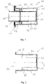
- In 1 Generally designated 10 is a combustor assembly for a fuel-powered vehicle heater.
- the 1 Combustion chamber assembly 10 shown in a longitudinal sectional view along a central longitudinal axis L of the combustion chamber assembly includes, as essential components, an in 2 Housing 12, also shown in longitudinal section, and an in 3 Combustion chamber housing 14 shown in longitudinal section.
- the housing 12 shown in FIG. 12 has a basically pot-like structure with a peripheral wall 16 and a bottom wall 18 adjoining it.
- a ring-like fastening flange 20 is provided on the peripheral wall 16 , which grips radially outward with respect to the longitudinal central axis L.
- heat transfer ribs 24 extending, for example, essentially in the direction of the central longitudinal axis L protrude from the peripheral wall 16 . These extend, starting from the bottom wall 18, close to that axial end region of the peripheral wall 16 at which the fastening flange 20 protrudes radially outward.
- Heat transfer ribs 26 that continue the heat transfer ribs 24 can also be provided in the area of the bottom wall 18 , for example.
- the housing 12 which is made of a metal material such as aluminum, in particular for reasons of thermal stability, can form part of a heat exchanger arrangement which can have, for example, another pot-like housing surrounding the housing 12, so that there is a flow space between the housing 12 and this additional housing a liquid heat transfer medium to be heated is formed.
- a heat exchanger arrangement which can have, for example, another pot-like housing surrounding the housing 12, so that there is a flow space between the housing 12 and this additional housing a liquid heat transfer medium to be heated is formed.
- the air to be heated and introduced into a vehicle interior can flow around the outside of the housing 12 , for example.
- Combustion chamber housing 14 shown provides, on the one hand, a peripheral wall 30 surrounding a combustion chamber 28 radially on the outside and a flame tube 32 adjoining peripheral wall 30 and, in the example shown, integrally formed therewith.
- a flame screen 34 is provided in the transition from the combustion chamber 28 or peripheral wall 30 to the flame tube 32 .
- a combustion chamber housing support 36 is provided on the outside, which provides a fastening flange area 38 reaching radially outward.
- a base assembly to be provided on the axial end region of the peripheral wall 30 remote from the flame tube 32, which base assembly closes off the combustion chamber 28 axially.
- a porous evaporator medium can be provided on such a base assembly, for example, into which liquid fuel is fed and from which the liquid fuel can exit in the form of vapor into the combustion chamber 28 .
- An electrically excitable heater can be associated with such a porous evaporator medium in order to support the evaporation of the fuel, particularly in the starting phase of the combustion operation.
- the combustion air to be mixed with the fuel vapor for combustion can also be introduced via the base assembly or base wall (not shown) or an air inlet connection provided thereon. Alternatively or additionally, this combustion air can flow into the combustion chamber 28 via air inlet openings provided in the peripheral wall 30 .
- the peripheral wall 30 or the flame tube 32 formed integrally therewith, for example, the flame screen 34 and the combustion chamber housing support 36 can be constructed, for example, from sheet metal material.
- the 1 shows that in the assembled state, the combustion chamber housing 14 is inserted into the housing 12, so that the two fastening flange regions 20, 38 extending radially outwards are located axially next to one another.
- the combustion chamber assembly 10 can be connected to a housing that also delimits the air flow space leading to the combustion chamber 28 , for example.
- the sealing disks 40, 42 are preferably made of flexible, i.e. deformable and heat-resistant material, so that the sealing disks 40, 42 can be clamped between the two fastening flange regions 20, 38 by applying appropriate force via the screw bolts already mentioned above, creating a tight seal.
- the 1 1 shows that inside the flame tube 32 an exhaust gas flow space 46 is formed which is open towards the bottom wall 18 of the housing 12 .
- the combustion exhaust gases produced during combustion in the combustion chamber 28 flow along the exhaust gas flow space 46 towards the bottom wall 18 and are deflected there radially outwards when exiting the flame tube 32 .
- the combustion exhaust gases then enter a first axial end region 48 of an exhaust gas return flow space, designated generally by 50 and formed between the outside of the flame tube 32 and the peripheral wall 16 of the housing 12 .
- the exhaust gases flow along the heat transfer fins 24 through the exhaust gas return flow chamber 50 and transfer heat to the housing 10 through contact with the heat transfer fins 24 and the inner surface of the peripheral wall 16.
- the combustion exhaust gases flowing in the exhaust gas return flow space 50 along the heat transfer fins 24 flow in the direction of a second axial end region 52 of the exhaust gas return flow space 50 .
- the heat transfer ribs 24 end and is in Exhaust gas recirculation space 50 is provided a generally designated 54 catalyst assembly.
- the z. B. Catalyst arrangement 54 embodied, for example, generally as an oxidation catalyst, can be constructed with a ring-like carrier, through which exhaust gas can basically flow, on the surface of which a catalytically active coating can be provided.
- this support can be porous or designed with a honeycomb structure in order to be able to provide a large catalytically active surface.
- Catalyst arrangement 54 which can also be seen, has a ring-like structure that is adapted to the ring-like cross-sectional geometry of exhaust gas recirculation chamber 50, so that it can be positioned between flame tube 32 or peripheral wall 30 of combustion chamber housing 14 and peripheral wall 16 of housing 10 essentially without radial movement play.
- the catalytic converter arrangement 54 In the direction away from the first axial end region 48 of the exhaust gas recirculation space 50, the catalytic converter arrangement 54 can be supported axially on a radial widened region 56 of the combustion chamber housing support 36 and thus held in a defined position.
- the catalytic converter arrangement 54 In the direction of the first axial end region 48, the catalytic converter arrangement 54 can be supported axially by the heat transfer ribs 24 protruding inwards from the peripheral wall 16 and can thus be held in a defined position.
- a heating area 58 also shaped like a ring, of an electrically excitable heating device, generally designated 60 , can be arranged between the ring-like catalyst arrangement 54 and the heat transfer fins 24 .
- the heating device 60 can be constructed, for example, with a heating conductor 62, in which case the heating conductor 62 can preferably be in the form of a sheathed heating conductor.
- a thermally effective heating element running inside the same is surrounded by a sheath that is also electrically conductive, so that the sheath forms a conducting region of the heating conductor.
- this jacket can be coated with electrically insulating material on its outside and, of course, also on the inside with respect to the heating element.
- the heating conductor 36 can be bent into a circular configuration to match the ring-like structure of the catalytic converter arrangement 54 or the exhaust gas return flow space 50, so that an end region 64 of the heating conductor 62 closes the ring-like structure. In this area, the heating conductor can be led out of the area of the exhaust gas return flow chamber 50 with a connecting section that first extends radially outwards, then axially and then further radially outwards.
- positioning recesses 66 which are open axially and do not completely accommodate the heating area 58 are provided in the axial end areas of the heat transfer ribs 24 .
- the heating area 58 When the heating area 58 is accommodated in the positioning indentations 66 , it protrudes axially beyond the heat transfer ribs 24 so that there is direct heat transfer contact between the heating area 58 and the catalyst arrangement 54 supported on the heat transfer ribs 24 .
- the positioning recess 66 is extended radially outwards as far as the peripheral wall 16 in order to accommodate the radially outwardly extending section 68 of the heating conductor 62 in this area.
- the catalytic converter arrangement 54 can have a corresponding recess in this peripheral area that passes through it axially.
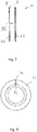
- the Figures 7 and 8 show in conjunction with the 1 that the sealing arrangement 44 is such that the heating conductor 62 can be passed through it to the outside.
- the sealing disk 42 directly adjoining the fastening flange region 20 and thus axially directly closing off the exhaust gas return flow chamber 50 has a passage opening 72 for the essentially axially extending section 70 of the heat conductor 62 .
- an axially open recess 74 extends radially outwards, which extends a corresponding axially and radially outwardly open recess 76 of the other sealing disk 40 axially opposite.
- the heating conductor 62 is held or accommodated with its radially extending section 78 adjoining the axially extending section 70 between the two sealing disks 40, 42 in the respective recesses 74, 76 of the same. Due to the flexibility of the sealing disks 40, 42 and the fastening of the housing 12 together with the combustion chamber housing support 36 by the already mentioned screw bolts, the two sealing disks 40, 42 are deformed in such a way that they also enclose the area of the heating conductor 62 passing through them in a gas-tight manner.
- the force exerted on the housing 12, in particular also axially, causes the latter to be moved towards the combustion chamber housing support 36, with deformation of the sealing arrangement 44, which makes it possible to position the catalytic converter arrangement 54 between the radial widened region 56 of the combustion chamber housing support 36 and the heat transfer ribs 24 of the housing 12 or to clamp the heating area 58 of the heating device 60 that is axially supported on it in a defined position.
- the provision of the heating device in association with the catalytic converter arrangement 54 creates the possibility of preheating the catalytic converter arrangement 54 in or before the starting phase of the combustion operation by energizing the heating device 60, so that it already has a temperature above a light-off temperature at the beginning of the combustion and also in the starting phase of the combustion operation, it is ensured that a lower level of pollutant emissions can be achieved, in particular by reducing the CO content and the HC content in the exhaust gases.
- the heating area 58 of the heating device 60 can have a structure that deviates from an exactly circular geometry.
- the heating region 62 may be constructed with a plurality of spirally extending turns, or may extend around the central longitudinal axis in a wavy or zigzag pattern. A meandering course in the circumferential direction and/or in the radial direction is also conceivable.
- the catalytic converter arrangement 54 could move closer to the first axial end region 58 of the exhaust gas recirculation space 50, so that, for example, the catalytic converter arrangement 54 could be positioned approximately in a central longitudinal region of the exhaust gas recirculation space 50.
- several such catalytically active arrangements could also be provided one after the other in the direction of flow, in which case, for example, such a heating device could be assigned to one or more of these catalytic converter arrangements.
- Other components, such as a hydrocarbon reservoir, for example, can also be provided upstream of the catalytic converter arrangement in the exhaust gas recirculation space.
Landscapes
- Engineering & Computer Science (AREA)
- Mechanical Engineering (AREA)
- Physics & Mathematics (AREA)
- Thermal Sciences (AREA)
- General Engineering & Computer Science (AREA)
- Chemical & Material Sciences (AREA)
- Combustion & Propulsion (AREA)
- Air-Conditioning For Vehicles (AREA)
- Exhaust Gas After Treatment (AREA)
Description
- Die vorliegende Erfindung betrifft eine Brennkammerbaugruppe gemäß dem Oberbegriff des Anspruchs 1, die in einem brennstoffbetriebenen Fahrzeugheizgerät dazu dient, durch Verbrennung eines Brennstoff/Luft-Gemisches Wärme transportierende Verbrennungsabgase bereitzustellen, um diese Wärme auf ein zu erwärmendes Medium, beispielsweise die in einen Fahrzeuginnenraum einzuleitende Luft oder ein in einem Wärmeträgermediumkreislauf zirkulierenden flüssiges Wärmeträgermedium, zu übertragen.
- Aus der nachveröffentlichten deutschen Patentanmeldung
DE 10 2016 117 408 ist eine Brennkammerbaugruppe bekannt, bei der durch das Vorsehen der Katalysatoranordnung im Abgasrückströmungsraum durch die an der Katalysatoranordnung ablaufende katalytische Reaktion insbesondere der CO-Anteil und der HC-Anteil in den Verbrennungsabgasen wesentlich verringert werden. - Aus der
EP 0 287 923 A2 ist eine Brennkammerbaugruppe gemäß dem Oberbegriff des Anspruchs 1 bekannt. - Es ist die Aufgabe der vorliegenden Erfindung, eine derartige Brennkammerbaugruppe so weiterzubilden, dass eine im Abgasrückströmungsraum angeordnete Katalysatoranordnung eine erhöhte Effizienz in der Schadstoffverringerung bereitstellen kann.
- Erfindungsgemäß wird diese Aufgabe gelöst durch eine Brennkammerbaugruppe für ein brennstoffbetriebenes Fahrzeugheizgerät gemäß Anspruch 1. Diese umfasst ein Brennkammergehäuse mit einer durch eine Umfangswandung begrenzten Brennkammer und einem in Richtung einer Gehäuselängsachse auf die Umfangswandung folgenden und einen in Richtung der Gehäuselängsachse offenen Abgasströmungsraum umgebenden Flammrohr, wobei zwischen dem Flammrohr und einem dieses umgebenden Gehäuse ein Abgasrückströmungsraum gebildet ist, wobei in einem ersten axialen Endbereich des Abgasrückströmungsraums der Abgasströmungsraum zum Abgasrückströmungsraum offen ist und im Abgasrückströmungsraum eine von im Abgasrückströmungsraum strömenden Verbrennungsabgasen durchströmbare Katalysatoranordnung vorgesehen ist.
- Eine kompakte, gleichwohl einen effizienten Betrieb der Katalysatoranordnung gewährleistende Ausgestaltung wird dadurch erreicht, dass an dem Gehäuse in den Abgasrückströmungsraum vorstehende Wärmeübertragungsrippen vorgesehen sind, und dass die Katalysatoranordnung im Abgasrückströmungsraum auf die Wärmeübertragungsrippen folgend angeordnet ist.
- Diese Brennkammerbaugruppe zeichnet sich dadurch aus, dass eine Heizeinrichtung zum Erwärmen der Katalysatoranordnung vorgesehen ist.
- Durch das Vorsehen einer der Katalysatoranordnung zugeordneten Heizeinrichtung wird es möglich, die Katalysatoranordnung nicht nur im stationären Betrieb, also einem Zustand, in welchem im Wesentlichen alle Systemkomponenten der Brennkammerbaugruppe durch die diese durchströmenden Verbrennungsabgase auf Betriebstemperatur gebracht sind bzw. gehalten werden, effizient zu betreiben und damit den CO- bzw. den HC-Gehalt in den Verbrennungsabgasen bis nahe an die Nachweisgrenze zu reduzieren und auch die ansonsten beim Abschalten eines mit einer derartigen Brennkammerbaugruppe aufgebauten Fahrzeugheizgeräts auftretenden Abschalt-Spitzen im CO- und HC-Ausstoß wesentlich zu verringern. Vielmehr wird mit dem erfindungsgemäßen Aufbau die Möglichkeit geschaffen, die Katalysatoranordnung insbesondere auch bei niedrigen Umgebungstemperaturen bereits vor bzw. bei Betriebsbeginn zu erwärmen und auf eine Temperatur im Bereich oder über der Anspringtemperatur von beispielsweise etwa 200 °C zu bringen bzw. auf dieser Temperatur zu halten, bis mit einsetzender Verbrennung und dabei die Brennkammerbaugruppe und auch die Katalysatoranordnung durchströmenden Verbrennungsabgasen auch ohne fortgesetzte Erregung der Heizeinrichtung im Bereich der Katalysatoranordnung die für eine effiziente katalytische Reaktion erforderliche Temperatur gewährleistet ist.
- Für einen sehr effizienten Betrieb der Heizeinrichtung wird vorgeschlagen, dass diese wenigstens bereichsweise in Wärmeübertragungskontakt mit der Katalysatoranordnung steht. Auf diese Art und Weise ist ein direkter Wärmeübertrag durch Wärmeleitung auf die Katalysatoranordnung gewährleistet, so dass Wärmeverluste auch weitestgehend ausgeschlossen werden können.
- Um den in einem Heizgerät bzw. einer Brennkammerbaugruppe dafür verfügbaren Bauraum möglichst effizient zu nutzen, ist die Katalysatoranordnung die Gehäuselängsachse ringartig umgebend ausgebildet, und die Heizeinrichtung weist einen die Gehäuselängsachse ringartig umgebenden Heizbereich auf.
- Eine kompakte, gleichwohl einen effizienten Betrieb der Katalysatoranordnung gewährleistende Ausgestaltung kann weiter dadurch erreicht werden, dass die Katalysatoranordnung in einem zweiten axialen Endbereich des Abgasrückströmungsraums angeordnet ist.
- Um mit der Heizeinrichtung nicht nur die Katalysatoranordnung, sondern auch an diese unmittelbar anschließende Bereiche der Brennkammerbaugruppe vorwärmen zu können, ist der Heizbereich zwischen der Katalysatoranordnung und den Wärmeübertragungsrippen angeordnet und steht in Wärmeübertragungskontakt mit der Katalysatoranordnung und den Wärmeübertragungsrippen. Dabei kann die die Katalysatoranordnung in Richtung auf den ersten axialen Endbereich des Abgasrückströmungsraums zu bezüglich der Wärmeübertragungsrippen axial abgestützt sein.
- Für eine definierte Positionierung der Katalysatoranordnung kann ferner dadurch gesorgt werden, dass die Katalysatoranordnung in Richtung von dem ersten axialen Endbereich weg bezüglich eines Brennkammergehäuseträgers axial abgestützt ist.
- Um in einfacher Art und Weise einen thermischen Kontakt zwischen der Heizeinrichtung und der im Abgasrückströmungsraum positionierten Katalysatoranordnung erreichen zu können, wird vorgeschlagen, dass eine den Abgasrückströmungsraum gasdicht abschließende Dichtanordnung vorgesehen ist, und dass die Dichtanordnung eine Durchführungsaussparung für die Heizeinrichtung aufweist. Diese Dichtanordnung kann beispielsweise zwischen dem Brennkammergehäuseträger und dem Gehäuse angeordnet sein.
- Die Heizeinrichtung umfasst vorzugsweise einen elektrisch erregbaren Heizleiter. Ein derartiger elektrisch erregbar Heizleiter bildet einerseits eine kompakte und effizient betreibbare Baugruppe, die andererseits auch in vielfältiger und leicht an bauliche Gegebenheiten anpassbarer Konfiguration in eine Brennkammerbaugruppe integriert werden kann.
- Der Heizleiter kann beispielsweise ein Mantel-Heizleiter sein. In einem derartigen Mantel-Heizleiter kann der ein innen liegendes Heizelement umschließenden Mantel an das Heizelement elektrisch angekoppelt sein und somit einen Leiterbereich des Heizleiters bilden.
- Die vorliegende Erfindung betrifft ferner ein mit einer erfindungsgemäß aufgebauten Brennkammerbaugruppe ausgestattetes Fahrzeugheizgerät.
- Die Erfindung wird nachfolgend mit Bezug auf die beiliegenden Figuren detailliert beschrieben. Es zeigt:
- Fig. 1
- in Längsschnitt eine Brennkammerbaugruppe für ein Fahrzeugheizgerät;
- Fig. 2
- in Alleinstellung ein einen Teil einer Wärmetauscheranordnung bereitstellendes Gehäuse der Brennkammerbaugruppe der
Fig. 1 ; - Fig. 3
- ein Brennkammergehäuse mit einem Flammrohr und einem Brennkammergehäuseträger;
- Fig. 4
- eine Schnittdarstellung einer Katalysatoranordnung der Brennkammerbaugruppe der
Fig. 1 ; - Fig. 5
- eine Heizeinrichtung der Brennkammerbaugruppe der
Fig. 1 , betrachtet in Blickrichtung V inFig. 6 ; - Fig. 6
- die Heizeinrichtung der
Fig. 5 , betrachtet in Blickrichtung VI inFig. 5 ; - Fig. 7
- eine mit zwei Dichtscheiben aufgebaute Dichtanordnung der Brennkammerbaugruppe der
Fig. 1 ; - Fig. 8
- eine Dichtscheibe der in
Fig. 7 dargestellten Dichtanordnung in Blickrichtung VIII. - In
Fig. 1 ist eine Brennkammerbaugruppe für ein brennstoffbetriebenes Fahrzeugheizgerät allgemein mit 10 bezeichnet. Die inFig. 1 in Längsschnittansicht, geschnitten längs einer Längsmittenachse L der Brennkammerbaugruppe dargestellte Brennkammerbaugruppe 10 umfasst als wesentliche Bestandteile ein inFig. 2 ebenfalls in Längsschnitt dargestelltes Gehäuse 12 sowie ein inFig. 3 im Längsschnitt dargestelltes Brennkammergehäuse 14. - Das in Fig. 12 dargestellte Gehäuse 12 weist eine grundsätzlich topfartige Struktur mit einer Umfangswandung 16 und einer daran anschließenden Bodenwandung 18 auf. An dem von der Bodenwandung 18 entfernten axialen Endbereich der Umfangswandung 16 ist ein nach radial außen bezüglich der Längsmittenachse L greifender, ringartiger Befestigungsflansch 20 an der Umfangswandung 16 vorgesehen. An der einem Innenraum 22 des Gehäuses 12 zugewandten Seite stehen von der Umfangswandung 16 sich beispielsweise im Wesentlichen in Richtung der Längsmittenachse L erstreckende Wärmeübertragungsrippen 24 vor. Diese erstrecken sich ausgehend von der Bodenwandung 18 bis nahe an denjenigen axialen Endbereich der Umfangswandung 16, an welchem der Befestigungsflansch 20 nach radial außen hervorsteht. Hiervon können auch im Bereich der Bodenwandung 18 beispielsweise die Wärmeübertragungsrippen 24 fortsetzende Wärmeübertragungsrippen 26 vorgesehen sein.
- Das insbesondere auch aus Gründen der thermischen Stabilität aus Metallmaterial, beispielsweise Aluminium, aufgebaute Gehäuse 12 kann einen Teil einer Wärmetauscheranordnung bilden, die beispielsweise ein weiteres das Gehäuse 12 umgebendes topfartiges Gehäuse aufweisen kann, so dass zwischen dem Gehäuse 12 und diesem weiteren Gehäuse ein Strömungsraum für ein zu erwärmendes, flüssiges Wärmeträgermedium gebildet ist. Alternativ kann das Gehäuse 12 an seiner Außenseite beispielsweise von der zu erwärmenden und in einen Fahrzeuginnenraum einzuleitenden Luft umströmt werden.
- Das in
Fig. 3 dargestellte Brennkammergehäuse 14 stellt einerseits eine eine Brennkammer 28 radial außen umgrenzende Umfangswandung 30 sowie ein an die Umfangswandung 30 anschließendes, im dargestellten Beispiel mit dieser integral ausgebildetes Flammrohr 32 bereit. Im Übergang von der Brennkammer 28 bzw. Umfangswandung 30 zum Flammrohr 32 ist eine Flammblende 34 vorgesehen. Näherungsweise im Bereich der Anbindung der Flammblende 34 an die Umfangswandung 30 bzw. das Flammrohr 32 ist an der Außenseite ein Brennkammergehäuseträger 36 vorgesehen, welcher einen nach radial außen greifenden Befestigungsflanschbereich 38 bereitstellt. - Nicht dargestellt ist in
Fig. 3 eine an dem vom Flammrohr 32 entfernten axialen Endbereich der Umfangswandung 30 vorzusehende Bodenbaugruppe, welche die Brennkammer 28 axial abschließt. An einer derartigen Bodenbaugruppe kann beispielsweise ein poröses Verdampfermedium vorgesehen sein, in welches flüssiger Brennstoff eingespeist wird und aus welchem der flüssige Brennstoff in Dampfform in die Brennkammer 28 austreten kann. Einem derartigen porösen Verdampfermedium kann eine elektrisch erregbare Heizung zugeordnet sein, um insbesondere in der Startphase des Verbrennungsbetriebs die Brennstoffabdampfung zu unterstützen. Ferner kann beispielsweise ebenfalls die über nicht dargestellte Bodenbaugruppe bzw. Bodenwandung bzw. einen daran vorgesehenen Lufteinleitstutzen die zur Verbrennung mit dem Brennstoffdampf zu mischende Verbrennungsluft eingeleitet werden. Alternativ oder zusätzlich kann diese Verbrennungsluft über in der Umfangswandung 30 vorgesehene Lufteintrittsöffnungen in die Brennkammer 28 einströmen. - Die Umfangswandung 30 bzw. das damit beispielsweise integral ausgebildete Flammrohr 32, die Flammblende 34 und der Brennkammergehäuseträger 36 können beispielsweise aus Blechmaterial aufgebaut sein.
- Die
Fig. 1 zeigt, dass im Zusammenbauzustand das Brennkammergehäuse 14 in das Gehäuse 12 eingesetzt ist, so dass die beiden nach radial außen greifenden Befestigungsflanschbereiche 20, 38 axial nebeneinander liegen. Mit nicht dargestellten und die Befestigungsflanschbereiche 20, 38 durchsetzenden Schraubbolzen oder dergleichen, kann die Brennkammerbaugruppe 10 an ein beispielsweise auch den zur Brennkammer 28 führenden Luftströmungsraum begrenzendes Gehäuse angebunden werden. Um im Angrenzungsbereich des Brennkammergehäuseträgers 36 an das Gehäuse 12, also im Bereich der nebeneinander liegenden Befestigungsflanschbereiche 20, 38, einen gegen den Austritt von Abgas dichten Abschluss zu erreichen, ist eine in denFig. 7 und 8 detaillierter dargestellte und mit zwei ringartig ausgebildeten Dichtscheiben 40, 42 aufgebaute Dichtanordnung 44 zwischen den beiden Befestigungsflanschbereichen 20, 38 angeordnet. - Die Dichtscheiben 40, 42 sind vorzugsweise aus flexiblem, also verformbarem und wärmebeständigem Material aufgebaut, so dass durch entsprechende Krafteinleitung über die vorangehend bereits angesprochenen Schraubbolzen die Dichtscheiben 40, 42, einen dichten Abschluss herstellend, zwischen den beiden Befestigungsflanschbereichen 20, 38 eingespannt werden können.
- Die
Fig. 1 veranschaulicht, dass im Inneren des Flammrohrs 32 ein in Richtung zur Bodenwandung 18 des Gehäuses 12 offener Abgasströmungsraum 46 gebildet ist. Die bei der Verbrennung in der Brennkammer 28 entstehenden Verbrennungsabgase strömen entlang des Abgasströmungsraums 46 auf die Bodenwandung 18 zu und werden dort beim Austritt aus dem Flammrohr 32 nach radial außen umgelenkt. Die Verbrennungsabgase treten dann in einen ersten axialen Endbereich 48 eines allgemein mit 50 bezeichneten und zwischen der Außenseite des Flammrohrs 32 und der Umfangswandung 16 des Gehäuses 12 gebildeten Abgasrückströmungsraum ein. Die Abgase strömen dabei entlang der Wärmeübertragungsrippen 24 durch den Abgasrückströmungsraum 50 und übertragen durch den Kontakt mit den Wärmeübertragungsrippen 24 und der Innenoberfläche der Umfangswandung 16 Wärme auf das Gehäuse 10. - Die im Abgasrückströmungsraum 50 entlang der Wärmeübertragungsrippen 24 strömenden Verbrennungsabgase strömen in Richtung auf einen zweiten axialen Endbereich 52 des Abgasrückströmungsraums 50 zu. In diesem zweiten axialen Endbereich 52 enden die Wärmeübertragungsrippen 24 und ist im Abgasrückströmungsraum 50 eine allgemein mit 54 bezeichnete Katalysatoranordnung vorgesehen. Die z. B. allgemein als Oxidationskatalysator ausgebildete Katalysatoranordnung 54 kann mit einem ringartigen, grundsätzlich von Abgas durchströmbaren Träger aufgebaut sein, an dessen Oberfläche eine katalytisch wirksame Beschichtung vorgesehen sein. Beispielsweise kann dieser Träger porös oder mit wabenartiger Struktur ausgebildet sein, um eine große katalytisch wirksame Oberfläche bereitstellen zu können. Die in
Fig. 4 auch erkennbare Katalysatoranordnung 54 weist eine an die ringartige Querschnittsgeometrie des Abgasrückströmungsraums 50 angepasste ringartige Struktur auf, so dass sie im Wesentlichen ohne radiales Bewegungsspiel zwischen dem Flammrohr 32 bzw. der Umfangswandung 30 des Brennkammergehäuses 14 und der Umfangswandung 16 des Gehäuses 10 positioniert werden kann. In Richtung von dem ersten axialen Endbereich 48 des Abgasrückströmungsraums 50 weg kann die Katalysatoranordnung 54 an einem radialen Erweiterungsbereich 56 des Brennkammergehäuseträgers 36 axial abgestützt und somit in definierter Positionierung gehalten sein. In Richtung auf den ersten axialen Endbereich 48 zu kann die Katalysatoranordnung 54 durch die von der Umfangswandung 16 nach innen vorstehenden Wärmeübertragungsrippen 24 axial gestützt und somit in definierter Positionierung gehalten werden. - Zur Erlangung dieser Abstützwechselwirkung kann zwischen der ringartigen Katalysatoranordnung 54 und den Wärmeübertragungsrippen 24 ein ebenfalls ringartig geformter Heizbereich 58 einer allgemein mit 60 bezeichneten elektrisch erregbaren Heizeinrichtung angeordnet sein. Die Heizeinrichtung 60 kann beispielsweise mit einem Heizleiter 62 aufgebaut sein, wobei der Heizleiter 62 vorzugsweise als Mantel-Heizleiter ausgebildet sein kann. Bei einem derartigen Mantel-Heizleiter ist ein im Inneren desselben verlaufendes, thermisch wirksames Heizelement von einem ebenfalls elektrisch leitenden Mantel umgeben, so dass der Mantel einen Leitungsbereich des Heizleiters bildet. Um nach außen hin einen elektrischen Kurzschluss zu vermeiden, kann dieser Mantel an seiner Außenseite und selbstverständlich auch bezüglich des Heizelements nach innen mit elektrisch isolierendem Material überzogen sein.
- Der Heizleiter 36 kann in Anpassung an die ringartige Struktur der Katalysatoranordnung 54 bzw. des Abgasrückströmungsraums 50 in eine kreisartige Konfiguration gebogen sein, so dass ein Endbereich 64 des Heizleiters 62 die ringartige Struktur schließt. In diesem Bereich kann der Heizleiter mit einem zunächst radial nach außen, dann axial und dann weiter nach radial außen sich erstreckenden Anschlussabschnitt aus dem Bereich des Abgasrückströmungsraums 50 herausgeführt sein.
- Um eine definierte Positionierung insbesondere des ringartigen Heizbereichs 58 vorzusehen, sind in den axialen Endbereichen der Wärmeübertragungsrippen 24 axial offene und den Heizbereich 58 nicht vollständig aufnehmende Positioniereinsenkungen 66 vorgesehen. Bei in den Positioniereinsenkungen 66 aufgenommenem Heizbereich 58 steht dieser axial über die Wärmeübertragungsrippen 24 hervor, so dass ein direkter Wärmeübertragungskontakt zwischen dem Heizbereich 58 und der über diesen an den Wärmeübertragungsrippen 24 abgestützten Katalysatoranordnung 54 besteht. Im Bereich der in
Fig. 2 oben dargestellten Wärmeübertragungsrippe 24 ist die Positionieraussparung 66 nach radial außen bis an die Umfangswandung 16 hinaus verlängert, um in diesem Bereich den nach radial außen sich erstreckenden Abschnitt 68 des Heizleiters 62 aufzunehmen. Für die Durchführung des dann anschließenden und im Wesentlichen axial sich erstreckenden Abschnitts 70 des Heizleiters 62 kann in diesem Umfangsbereich die Katalysatoranordnung 54 eine entsprechende, diese axial durchsetzende Aussparung aufweisen. - Die
Fig. 7 und 8 zeigen in Verbindung mit derFig. 1 , dass die Dichtanordnung 44 so beschaffen ist, dass der Heizleiter 62 durch diese hindurch nach außen geführt werden kann. Zu diesem Zwecke weist die unmittelbar an den Befestigungsflanschbereich 20 anschließende und somit den Abgasrückströmungsraum 50 axial direkt abschließende Dichtscheibe 42 eine Durchtrittsöffnung 72 für den im Wesentlichen axial sich erstreckenden Abschnitt 70 des Heizleiters 62 auf. Von der Durchtrittsöffnung 72 erstreckt eine axial offene Aussparung 74 sich nach radial außen, welcher eine entsprechende, axial und nach radial außen offene Aussparung 76 der anderen Dichtscheibe 40 axial gegenüberliegt. Somit ist der Heizleiter 62 mit seinem radial sich erstreckenden und an den axial sich erstreckenden Abschnitt 70 anschließenden Abschnitt 78 zwischen den beiden Dichtscheiben 40, 42 in den jeweiligen Aussparungen 74, 76 derselben gehalten bzw. aufgenommen. Aufgrund der Flexibilität der Dichtscheiben 40, 42 und der bei der Befestigung des Gehäuses 12 zusammen mit dem Brennkammergehäuseträger 36 durch die bereits angesprochenen Schraubbolzen werden die beiden Dichtscheiben 40, 42 so verformt, dass sie auch den diese durchsetzenden Bereich des Heizleiters 62 gasdicht umschließen. Durch die dabei insbesondere auch axial auf das Gehäuse 12 ausgeübte Kraft wird dieses unter Verformung der Dichtanordnung 44 auf den Brennkammergehäuseträger 36 zu bewegt, wodurch die Möglichkeit geschaffen ist, die Katalysatoranordnung 54 zwischen dem radialen Erweiterungsbereich 56 des Brennkammergehäuseträgers 36 und den Wärmeübertragungsrippen 24 des Gehäuses 12 bzw. dem daran sich axial abstützenden Heizbereich 58 der Heizeinrichtung 60 in definierter Positionierung zu klemmen. - Durch das Vorsehen der Heizeinrichtung in Zuordnung zur Katalysatoranordnung 54 wird die Möglichkeit geschaffen, in bzw. vor der Startphase des Verbrennungsbetriebs durch Erregung der Heizeinrichtung 60 die Katalysatoranordnung 54 vorzuwärmen, so dass diese bereits bei Beginn der Verbrennung eine über einer Anspringtemperatur liegende Temperatur aufweist und auch in der Startphase des Verbrennungsbetriebs gewährleistet ist, dass insbesondere durch Verringerung des CO-Gehalts und des HC-Gehalts in den Abgasen ein geringer Schadstoffausstoß erreicht werden kann. Da bei der erfindungsgemäßen Ausgestaltung durch den Heizbereich 58 der Heizeinrichtung nicht nur die Katalysatoranordnung 54, sondern auch die diese stützenden axialen Endbereiche der Wärmeübertragungsrippen 24 vorgewärmt werden können, wird am Beginn des Verbrennungsbetriebs durch das den Abgasrückströmungsraum 50 durchströmende Abgas in den Wärmeübertragungsrippen 24 gespeicherte Wärme auf die Katalysatoranordnung 24 zu getragen und somit weiter effizient zur Erwärmung der Katalysatoranordnung 54 genutzt.
- Es ist abschließend darauf hinzuweisen, dass, abweichend von der dargestellten Ausgestaltung, unter Beibehalt der Prinzipien der vorliegenden Erfindung konstruktive Änderungen vorgesehen werden können. So kann beispielsweise der Heizbereich 58 der Heizeinrichtung 60 eine von einer exakt kreisrunden Geometrie abweichende Struktur aufweisen. Beispielsweise kann der Heizbereich 62 mit mehreren, spiralartig sich erstreckenden Windungen aufgebaut sein oder kann mit einer wellenartigen oder einer zickzackartigen Struktur sich um die Längsmittenachse herum erstrecken. Auch ein mäanderartiger Verlauf in Umfangsrichtung oder/und in Radialrichtung ist denkbar.
- Ferner könnte die Katalysatoranordnung 54 bei entsprechend kürzerer Ausgestaltung der Wärmeübertragungsrippen 24 näher an den ersten axialen Endbereich 58 des Abgasrückströmungsraums 50 heranrücken, so dass beispielsweise die Katalysatoranordnung 54 näherungsweise in einem Längenmittenbereich des Abgasrückströmungsraums 50 positioniert sein könnte. Grundsätzlich könnten auch mehrere derartige katalytisch wirksame Anordnungen in Strömungsrichtung aufeinanderfolgend vorgesehen sein, wobei dann beispielsweise einer oder mehreren dieser Katalysatoranordnungen eine derartige Heizeinrichtung zugeordnet sein kann. Auch können andere Komponenten, wie beispielsweise ein Kohlenwasserstoffspeicher beispielsweise stromaufwärts bezüglich der Katalysatoranordnung im Abgasrückströmungsraum vorgesehen sein.
Claims (10)
- Brennkammerbaugruppe für ein brennstoffbetriebenes Fahrzeugheizgerät, umfassend ein Brennkammergehäuse (14) mit einer durch eine Umfangswandung (30) begrenzten Brennkammer (28) und einem in Richtung einer Gehäuselängsachse (L) auf die Umfangswandung (30) folgenden und einen in Richtung der Gehäuselängsachse (L) offenen Abgasströmungsraum (46) umgebenden Flammrohr (32), wobei zwischen dem Flammrohr (32) und einem dieses umgebenden Gehäuse (12) ein Abgasrückströmungsraum (50) gebildet ist, wobei an dem Gehäuse (12) in den Abgasrückströmungsraum (50) vorstehende Wärmeübertragungsrippen (24) vorgesehen sind und in einem ersten axialen Endbereich (48) des Abgasrückströmungsraums (50) der Abgasströmungsraum (46) zum Abgasrückströmungsraum (50) offen ist, dadurch gekennzeichnet,- dass im Abgasrückströmungsraum (50) eine von im Abgasrückströmungsraum (50) strömenden Verbrennungsabgasen durchströmbare Katalysatoranordnung (54) vorgesehen ist,- dass die Katalysatoranordnung (54) die Gehäuselängsachse (L) ringartig umgebend ausgebildet ist und im Abgasrückströmungsraum (50) auf die Wärmeübertragungsrippen (24) folgend angeordnet ist,- dass eine Heizeinrichtung (60) zum Erwärmen der Katalysatoranordnung (54) vorgesehen ist, wobei die Heizeinrichtung (60) einen die Gehäuselängsachse (L) ringartig umgebenden Heizbereich (58) aufweist, und- dass der Heizbereich (58) zwischen der Katalysatoranordnung (54) und den Wärmeübertragungsrippen (24) angeordnet ist und in Wärmeübertragungskontakt mit der Katalysatoranordnung (54) und den Wärmeübertragungsrippen (24) steht.
- Brennkammerbaugruppe nach Anspruch 1, dadurch gekennzeichnet, dass die Heizeinrichtung (60) wenigstens bereichsweise in Wärmeübertragungskontakt mit der Katalysatoranordnung (54) steht.
- Brennkammerbaugruppe nach einem der vorangehenden Ansprüche, dadurch gekennzeichnet, dass die Katalysatoranordnung (54) in einem zweiten axialen Endbereich (52) des Abgasrückströmungsraums (50) angeordnet ist.
- Brennkammerbaugruppe nach einem der vorangehenden Ansprüche, dadurch gekennzeichnet, dass die Katalysatoranordnung (54) in Richtung auf den ersten axialen Endbereich (48) des Abgasrückströmungsraums (50) zu bezüglich der Wärmeübertragungsrippen (24) axial abgestützt ist.
- Brennkammerbaugruppe nach einem der vorangehenden Ansprüche, dadurch gekennzeichnet, dass die Katalysatoranordnung (54) in Richtung von dem ersten axialen Endbereich (48) weg bezüglich eines Brennkammergehäuseträgers (36) axial abgestützt ist.
- Brennkammerbaugruppe nach einem der vorangehenden Ansprüche, dadurch gekennzeichnet, dass eine den Abgasrückströmungsraum (50) gasdicht abschließende Dichtanordnung (44) vorgesehen ist, und dass die Dichtanordnung (44) eine Durchführungsaussparung (72, 74, 76) für die Heizeinrichtung (60) aufweist.
- Brennkammerbaugruppe nach Anspruch 5 und Anspruch 6, dadurch gekennzeichnet, dass die Dichtanordnung (44) zwischen dem Brennkammergehäuseträger (36) und dem Gehäuse (12) angeordnet ist.
- Brennkammerbaugruppe nach einem der vorangehenden Ansprüche, dadurch gekennzeichnet, dass die Heizeinrichtung (60) einen elektrisch erregbaren Heizleiter (62) umfasst.
- Brennkammerbaugruppe nach Anspruch 8 dadurch gekennzeichnet, dass der Heizleiter (62) ein Mantel-Heizleiter ist.
- Fahrzeugheizgerät, umfassend einen Brennkammerbaugruppe (10) nach einem der vorangehenden Ansprüche.
Applications Claiming Priority (1)
| Application Number | Priority Date | Filing Date | Title |
|---|---|---|---|
| DE102018100216.5A DE102018100216B3 (de) | 2018-01-08 | 2018-01-08 | Brennkammerbaugruppe und Fahrzeugheizgerät |
Publications (2)
| Publication Number | Publication Date |
|---|---|
| EP3508787A1 EP3508787A1 (de) | 2019-07-10 |
| EP3508787B1 true EP3508787B1 (de) | 2022-08-03 |
Family
ID=64665749
Family Applications (1)
| Application Number | Title | Priority Date | Filing Date |
|---|---|---|---|
| EP18212830.6A Active EP3508787B1 (de) | 2018-01-08 | 2018-12-17 | Brennkammerbaugruppe |
Country Status (6)
| Country | Link |
|---|---|
| EP (1) | EP3508787B1 (de) |
| CN (1) | CN110014804B (de) |
| CA (1) | CA3029303C (de) |
| DE (1) | DE102018100216B3 (de) |
| PL (1) | PL3508787T3 (de) |
| RU (1) | RU2705876C1 (de) |
Families Citing this family (4)
| Publication number | Priority date | Publication date | Assignee | Title |
|---|---|---|---|---|
| DE102019109382A1 (de) * | 2019-04-10 | 2020-10-15 | Eberspächer Climate Control Systems GmbH | Wärmetauscherbaugruppe |
| DE102020100512A1 (de) * | 2020-01-13 | 2021-07-15 | Eberspächer Climate Control Systems GmbH | Fahrzeugheizgerät |
| DE102020102055B4 (de) | 2020-01-29 | 2025-08-14 | Eberspächer Climate Control Systems GmbH | Brennkammerbaugruppe |
| DE102021106678B4 (de) | 2021-03-18 | 2022-10-06 | Webasto SE | Heizvorrichtung, vorzugsweise brennstoffbetriebene Heizvorrichtung, für ein Fahrzeug, sowie Verfahren zur Montage einer Heizvorrichtung |
Family Cites Families (14)
| Publication number | Priority date | Publication date | Assignee | Title |
|---|---|---|---|---|
| US4345431A (en) * | 1980-03-25 | 1982-08-24 | Shimizu Construction Co. Ltd. | Exhaust gas cleaning system for diesel engines |
| EP0287923A3 (de) * | 1987-04-22 | 1990-03-21 | Webasto AG Fahrzeugtechnik | Heizgerät, insbesondere Fahrzeugzusatzheizgerät |
| JPH0823409B2 (ja) * | 1989-06-20 | 1996-03-06 | エミテツク ゲゼルシヤフト フユア エミツシオンス テクノロギー ミツト ベシユレンクテル ハフツング | ガス流中の燃料の無炎燃焼による熱発生方法と装置 |
| DE19617297A1 (de) * | 1996-04-30 | 1997-11-13 | Brand Gerhart Rosemarie | Simultane Detektion von oxidierbaren und reduzierbaren Gasen mit Metalloxidsensoren unter Einsatz von Impedanzspektroskopie |
| JP2991187B2 (ja) * | 1997-10-20 | 1999-12-20 | トヨタ自動車株式会社 | 燃焼式ヒータを有する内燃機関 |
| ITPD20050281A1 (it) * | 2005-09-28 | 2007-03-29 | Nonox Ltd | Metodo e dispositivo per abbattere le componenti inquinanti presenti nei fumi di scarico di un termo-generatore a combustione |
| JP4579282B2 (ja) * | 2007-10-26 | 2010-11-10 | カルソニックカンセイ株式会社 | 電気ヒータ装置 |
| FR2928846B1 (fr) * | 2008-03-20 | 2010-10-22 | Fondis Sa | Dispositif d'epuration a catalyseur des gaz et fumees de combustion d'un appareil de chauffage a combustible solide. |
| DE102008048796A1 (de) * | 2008-09-24 | 2010-03-25 | Emitec Gesellschaft Für Emissionstechnologie Mbh | Abgasreinigungssystem für Dieselmotoren |
| WO2012061795A2 (en) * | 2010-11-05 | 2012-05-10 | Clearstak Llc | Intelligently-controlled catalytic converter for biofuel-fired boiler |
| US9956848B2 (en) * | 2011-10-25 | 2018-05-01 | GM Global Technology Operations LLC | System and method for heating a vehicle cabin |
| DE102011087971B4 (de) * | 2011-12-08 | 2021-03-04 | Eberspächer Climate Control Systems GmbH | Verfahren zum Betreiben eines mit Kohlenwasserstoff-Brennstoff betreibbaren Heizgeräts |
| DE102013214387B4 (de) * | 2013-07-23 | 2020-10-22 | Eberspächer Climate Control Systems GmbH | Einströmelement, insbesondere für einen Verbrennungsluftströmungsweg im Fahrzeugheizgerät |
| DE102016117408B4 (de) | 2016-09-15 | 2020-11-26 | Eberspächer Climate Control Systems GmbH | Brennkammerbaugruppe für ein brennstoffbetriebenes Fahrzeugheizgerät |
-
2018
- 2018-01-08 DE DE102018100216.5A patent/DE102018100216B3/de active Active
- 2018-12-17 EP EP18212830.6A patent/EP3508787B1/de active Active
- 2018-12-17 PL PL18212830.6T patent/PL3508787T3/pl unknown
- 2018-12-26 RU RU2018146480A patent/RU2705876C1/ru active
-
2019
- 2019-01-07 CA CA3029303A patent/CA3029303C/en active Active
- 2019-01-07 CN CN201910010093.9A patent/CN110014804B/zh active Active
Also Published As
| Publication number | Publication date |
|---|---|
| PL3508787T3 (pl) | 2022-12-19 |
| EP3508787A1 (de) | 2019-07-10 |
| CN110014804B (zh) | 2022-08-30 |
| DE102018100216B3 (de) | 2019-03-21 |
| CN110014804A (zh) | 2019-07-16 |
| RU2705876C1 (ru) | 2019-11-12 |
| CA3029303A1 (en) | 2019-07-08 |
| CA3029303C (en) | 2021-06-15 |
Similar Documents
| Publication | Publication Date | Title |
|---|---|---|
| EP3508787B1 (de) | Brennkammerbaugruppe | |
| DE112018004729B4 (de) | Turbolader | |
| EP3296632B1 (de) | Brennkammerbaugruppe für ein brennstoffbetriebenes fahrzeugheizgerät | |
| EP3348905B1 (de) | Brennkammerbaugruppe | |
| DE4014214A1 (de) | Abgasreinigungsvorrichtung | |
| DE102016215290B4 (de) | Komponente eines Abgassystems und Verfahren zur Abgasnachbehandlung | |
| EP3611431A1 (de) | Brennkammerbaugruppe für ein fahrzeugheizgerät | |
| EP3848212B1 (de) | Fahrzeugheizgerät und verfahren zum betreiben des fahrzeugheizgerätes | |
| EP4155513B1 (de) | Abgasführungsgehäuse | |
| EP1464893B1 (de) | Brenneranordnung für ein Heizgerät und Heizgerät, insbesondere Fahrzeugheizgerät | |
| EP3954881B1 (de) | Abgasheizanordnung | |
| EP0693616B1 (de) | Vorrichtung zur katalytischen Reinigung bzw. Zerlegung von heissen Agbasen | |
| WO2020260337A1 (de) | Vorrichtung zur abgasnachbehandlung | |
| EP3510835A1 (de) | Ringförmiges heizelement | |
| EP3722694B1 (de) | Wärmetauscherbaugruppe | |
| EP1927489B1 (de) | Fahrzeugheizgerät | |
| EP2012058A2 (de) | Fahrzeugheizgerät | |
| DE102011051605A1 (de) | Heizeinrichtung | |
| DE102007051654A1 (de) | Heizelement für einen Verdampfer | |
| DE102021100570B4 (de) | Katalysator mit Heizscheibe | |
| EP1925477B1 (de) | Fahrzeugheizgerät | |
| EP1927488B2 (de) | Fahrzeugheizgerät | |
| WO2001092691A1 (de) | Mantelrohr mit thermisch isolierenden sicken | |
| DE102007038328B4 (de) | Kombiniertes Luft-/Flüssigkeits-Fahrzeugheizgerät | |
| DE102022113905A1 (de) | Anschlusseinheit |
Legal Events
| Date | Code | Title | Description |
|---|---|---|---|
| PUAI | Public reference made under article 153(3) epc to a published international application that has entered the european phase |
Free format text: ORIGINAL CODE: 0009012 |
|
| STAA | Information on the status of an ep patent application or granted ep patent |
Free format text: STATUS: THE APPLICATION HAS BEEN PUBLISHED |
|
| AK | Designated contracting states |
Kind code of ref document: A1 Designated state(s): AL AT BE BG CH CY CZ DE DK EE ES FI FR GB GR HR HU IE IS IT LI LT LU LV MC MK MT NL NO PL PT RO RS SE SI SK SM TR |
|
| AX | Request for extension of the european patent |
Extension state: BA ME |
|
| STAA | Information on the status of an ep patent application or granted ep patent |
Free format text: STATUS: REQUEST FOR EXAMINATION WAS MADE |
|
| 17P | Request for examination filed |
Effective date: 20200110 |
|
| RBV | Designated contracting states (corrected) |
Designated state(s): AL AT BE BG CH CY CZ DE DK EE ES FI FR GB GR HR HU IE IS IT LI LT LU LV MC MK MT NL NO PL PT RO RS SE SI SK SM TR |
|
| RAP1 | Party data changed (applicant data changed or rights of an application transferred) |
Owner name: EBERSPAECHER CLIMATE CONTROL SYSTEMS GMBH |
|
| STAA | Information on the status of an ep patent application or granted ep patent |
Free format text: STATUS: EXAMINATION IS IN PROGRESS |
|
| 17Q | First examination report despatched |
Effective date: 20210817 |
|
| GRAP | Despatch of communication of intention to grant a patent |
Free format text: ORIGINAL CODE: EPIDOSNIGR1 |
|
| STAA | Information on the status of an ep patent application or granted ep patent |
Free format text: STATUS: GRANT OF PATENT IS INTENDED |
|
| INTG | Intention to grant announced |
Effective date: 20220506 |
|
| GRAS | Grant fee paid |
Free format text: ORIGINAL CODE: EPIDOSNIGR3 |
|
| GRAA | (expected) grant |
Free format text: ORIGINAL CODE: 0009210 |
|
| STAA | Information on the status of an ep patent application or granted ep patent |
Free format text: STATUS: THE PATENT HAS BEEN GRANTED |
|
| AK | Designated contracting states |
Kind code of ref document: B1 Designated state(s): AL AT BE BG CH CY CZ DE DK EE ES FI FR GB GR HR HU IE IS IT LI LT LU LV MC MK MT NL NO PL PT RO RS SE SI SK SM TR |
|
| REG | Reference to a national code |
Ref country code: AT Ref legal event code: REF Ref document number: 1509024 Country of ref document: AT Kind code of ref document: T Effective date: 20220815 Ref country code: CH Ref legal event code: EP |
|
| REG | Reference to a national code |
Ref country code: DE Ref legal event code: R096 Ref document number: 502018010287 Country of ref document: DE |
|
| REG | Reference to a national code |
Ref country code: IE Ref legal event code: FG4D Free format text: LANGUAGE OF EP DOCUMENT: GERMAN |
|
| REG | Reference to a national code |
Ref country code: FI Ref legal event code: FGE |
|
| REG | Reference to a national code |
Ref country code: SE Ref legal event code: TRGR |
|
| REG | Reference to a national code |
Ref country code: LT Ref legal event code: MG9D |
|
| REG | Reference to a national code |
Ref country code: NL Ref legal event code: MP Effective date: 20220803 |
|
| PG25 | Lapsed in a contracting state [announced via postgrant information from national office to epo] |
Ref country code: RS Free format text: LAPSE BECAUSE OF FAILURE TO SUBMIT A TRANSLATION OF THE DESCRIPTION OR TO PAY THE FEE WITHIN THE PRESCRIBED TIME-LIMIT Effective date: 20220803 Ref country code: PT Free format text: LAPSE BECAUSE OF FAILURE TO SUBMIT A TRANSLATION OF THE DESCRIPTION OR TO PAY THE FEE WITHIN THE PRESCRIBED TIME-LIMIT Effective date: 20221205 Ref country code: NO Free format text: LAPSE BECAUSE OF FAILURE TO SUBMIT A TRANSLATION OF THE DESCRIPTION OR TO PAY THE FEE WITHIN THE PRESCRIBED TIME-LIMIT Effective date: 20221103 Ref country code: NL Free format text: LAPSE BECAUSE OF FAILURE TO SUBMIT A TRANSLATION OF THE DESCRIPTION OR TO PAY THE FEE WITHIN THE PRESCRIBED TIME-LIMIT Effective date: 20220803 Ref country code: LV Free format text: LAPSE BECAUSE OF FAILURE TO SUBMIT A TRANSLATION OF THE DESCRIPTION OR TO PAY THE FEE WITHIN THE PRESCRIBED TIME-LIMIT Effective date: 20220803 Ref country code: LT Free format text: LAPSE BECAUSE OF FAILURE TO SUBMIT A TRANSLATION OF THE DESCRIPTION OR TO PAY THE FEE WITHIN THE PRESCRIBED TIME-LIMIT Effective date: 20220803 Ref country code: ES Free format text: LAPSE BECAUSE OF FAILURE TO SUBMIT A TRANSLATION OF THE DESCRIPTION OR TO PAY THE FEE WITHIN THE PRESCRIBED TIME-LIMIT Effective date: 20220803 |
|
| PG25 | Lapsed in a contracting state [announced via postgrant information from national office to epo] |
Ref country code: IS Free format text: LAPSE BECAUSE OF FAILURE TO SUBMIT A TRANSLATION OF THE DESCRIPTION OR TO PAY THE FEE WITHIN THE PRESCRIBED TIME-LIMIT Effective date: 20221203 Ref country code: HR Free format text: LAPSE BECAUSE OF FAILURE TO SUBMIT A TRANSLATION OF THE DESCRIPTION OR TO PAY THE FEE WITHIN THE PRESCRIBED TIME-LIMIT Effective date: 20220803 Ref country code: GR Free format text: LAPSE BECAUSE OF FAILURE TO SUBMIT A TRANSLATION OF THE DESCRIPTION OR TO PAY THE FEE WITHIN THE PRESCRIBED TIME-LIMIT Effective date: 20221104 |
|
| PG25 | Lapsed in a contracting state [announced via postgrant information from national office to epo] |
Ref country code: SM Free format text: LAPSE BECAUSE OF FAILURE TO SUBMIT A TRANSLATION OF THE DESCRIPTION OR TO PAY THE FEE WITHIN THE PRESCRIBED TIME-LIMIT Effective date: 20220803 Ref country code: RO Free format text: LAPSE BECAUSE OF FAILURE TO SUBMIT A TRANSLATION OF THE DESCRIPTION OR TO PAY THE FEE WITHIN THE PRESCRIBED TIME-LIMIT Effective date: 20220803 Ref country code: DK Free format text: LAPSE BECAUSE OF FAILURE TO SUBMIT A TRANSLATION OF THE DESCRIPTION OR TO PAY THE FEE WITHIN THE PRESCRIBED TIME-LIMIT Effective date: 20220803 |
|
| REG | Reference to a national code |
Ref country code: DE Ref legal event code: R097 Ref document number: 502018010287 Country of ref document: DE |
|
| PG25 | Lapsed in a contracting state [announced via postgrant information from national office to epo] |
Ref country code: SK Free format text: LAPSE BECAUSE OF FAILURE TO SUBMIT A TRANSLATION OF THE DESCRIPTION OR TO PAY THE FEE WITHIN THE PRESCRIBED TIME-LIMIT Effective date: 20220803 Ref country code: EE Free format text: LAPSE BECAUSE OF FAILURE TO SUBMIT A TRANSLATION OF THE DESCRIPTION OR TO PAY THE FEE WITHIN THE PRESCRIBED TIME-LIMIT Effective date: 20220803 |
|
| PLBE | No opposition filed within time limit |
Free format text: ORIGINAL CODE: 0009261 |
|
| STAA | Information on the status of an ep patent application or granted ep patent |
Free format text: STATUS: NO OPPOSITION FILED WITHIN TIME LIMIT |
|
| PG25 | Lapsed in a contracting state [announced via postgrant information from national office to epo] |
Ref country code: AL Free format text: LAPSE BECAUSE OF FAILURE TO SUBMIT A TRANSLATION OF THE DESCRIPTION OR TO PAY THE FEE WITHIN THE PRESCRIBED TIME-LIMIT Effective date: 20220803 |
|
| 26N | No opposition filed |
Effective date: 20230504 |
|
| REG | Reference to a national code |
Ref country code: CH Ref legal event code: PL |
|
| GBPC | Gb: european patent ceased through non-payment of renewal fee |
Effective date: 20221217 |
|
| REG | Reference to a national code |
Ref country code: BE Ref legal event code: MM Effective date: 20221231 |
|
| PG25 | Lapsed in a contracting state [announced via postgrant information from national office to epo] |
Ref country code: SI Free format text: LAPSE BECAUSE OF FAILURE TO SUBMIT A TRANSLATION OF THE DESCRIPTION OR TO PAY THE FEE WITHIN THE PRESCRIBED TIME-LIMIT Effective date: 20220803 Ref country code: LU Free format text: LAPSE BECAUSE OF NON-PAYMENT OF DUE FEES Effective date: 20221217 |
|
| PG25 | Lapsed in a contracting state [announced via postgrant information from national office to epo] |
Ref country code: LI Free format text: LAPSE BECAUSE OF NON-PAYMENT OF DUE FEES Effective date: 20221231 Ref country code: IE Free format text: LAPSE BECAUSE OF NON-PAYMENT OF DUE FEES Effective date: 20221217 Ref country code: GB Free format text: LAPSE BECAUSE OF NON-PAYMENT OF DUE FEES Effective date: 20221217 Ref country code: CH Free format text: LAPSE BECAUSE OF NON-PAYMENT OF DUE FEES Effective date: 20221231 |
|
| PG25 | Lapsed in a contracting state [announced via postgrant information from national office to epo] |
Ref country code: BE Free format text: LAPSE BECAUSE OF NON-PAYMENT OF DUE FEES Effective date: 20221231 |
|
| PG25 | Lapsed in a contracting state [announced via postgrant information from national office to epo] |
Ref country code: HU Free format text: LAPSE BECAUSE OF FAILURE TO SUBMIT A TRANSLATION OF THE DESCRIPTION OR TO PAY THE FEE WITHIN THE PRESCRIBED TIME-LIMIT; INVALID AB INITIO Effective date: 20181217 |
|
| PG25 | Lapsed in a contracting state [announced via postgrant information from national office to epo] |
Ref country code: CY Free format text: LAPSE BECAUSE OF FAILURE TO SUBMIT A TRANSLATION OF THE DESCRIPTION OR TO PAY THE FEE WITHIN THE PRESCRIBED TIME-LIMIT Effective date: 20220803 |
|
| PG25 | Lapsed in a contracting state [announced via postgrant information from national office to epo] |
Ref country code: MK Free format text: LAPSE BECAUSE OF FAILURE TO SUBMIT A TRANSLATION OF THE DESCRIPTION OR TO PAY THE FEE WITHIN THE PRESCRIBED TIME-LIMIT Effective date: 20220803 Ref country code: IT Free format text: LAPSE BECAUSE OF FAILURE TO SUBMIT A TRANSLATION OF THE DESCRIPTION OR TO PAY THE FEE WITHIN THE PRESCRIBED TIME-LIMIT Effective date: 20220803 |
|
| PG25 | Lapsed in a contracting state [announced via postgrant information from national office to epo] |
Ref country code: MC Free format text: LAPSE BECAUSE OF FAILURE TO SUBMIT A TRANSLATION OF THE DESCRIPTION OR TO PAY THE FEE WITHIN THE PRESCRIBED TIME-LIMIT Effective date: 20220803 |
|
| PG25 | Lapsed in a contracting state [announced via postgrant information from national office to epo] |
Ref country code: MC Free format text: LAPSE BECAUSE OF FAILURE TO SUBMIT A TRANSLATION OF THE DESCRIPTION OR TO PAY THE FEE WITHIN THE PRESCRIBED TIME-LIMIT Effective date: 20220803 |
|
| PG25 | Lapsed in a contracting state [announced via postgrant information from national office to epo] |
Ref country code: BG Free format text: LAPSE BECAUSE OF FAILURE TO SUBMIT A TRANSLATION OF THE DESCRIPTION OR TO PAY THE FEE WITHIN THE PRESCRIBED TIME-LIMIT Effective date: 20220803 |
|
| PG25 | Lapsed in a contracting state [announced via postgrant information from national office to epo] |
Ref country code: MT Free format text: LAPSE BECAUSE OF FAILURE TO SUBMIT A TRANSLATION OF THE DESCRIPTION OR TO PAY THE FEE WITHIN THE PRESCRIBED TIME-LIMIT Effective date: 20220803 |
|
| REG | Reference to a national code |
Ref country code: AT Ref legal event code: MM01 Ref document number: 1509024 Country of ref document: AT Kind code of ref document: T Effective date: 20231217 |
|
| PG25 | Lapsed in a contracting state [announced via postgrant information from national office to epo] |
Ref country code: AT Free format text: LAPSE BECAUSE OF NON-PAYMENT OF DUE FEES Effective date: 20231217 |
|
| PG25 | Lapsed in a contracting state [announced via postgrant information from national office to epo] |
Ref country code: TR Free format text: LAPSE BECAUSE OF FAILURE TO SUBMIT A TRANSLATION OF THE DESCRIPTION OR TO PAY THE FEE WITHIN THE PRESCRIBED TIME-LIMIT Effective date: 20220803 |
|
| PGFP | Annual fee paid to national office [announced via postgrant information from national office to epo] |
Ref country code: FI Payment date: 20251216 Year of fee payment: 8 |
|
| PGFP | Annual fee paid to national office [announced via postgrant information from national office to epo] |
Ref country code: FR Payment date: 20251218 Year of fee payment: 8 |
|
| PGFP | Annual fee paid to national office [announced via postgrant information from national office to epo] |
Ref country code: SE Payment date: 20251217 Year of fee payment: 8 |
|
| PGFP | Annual fee paid to national office [announced via postgrant information from national office to epo] |
Ref country code: CZ Payment date: 20251204 Year of fee payment: 8 |
|
| PGFP | Annual fee paid to national office [announced via postgrant information from national office to epo] |
Ref country code: PL Payment date: 20251205 Year of fee payment: 8 |
|
| PGFP | Annual fee paid to national office [announced via postgrant information from national office to epo] |
Ref country code: DE Payment date: 20251222 Year of fee payment: 8 |
|
| PGFP | Annual fee paid to national office [announced via postgrant information from national office to epo] |
Ref country code: AT Payment date: 20260410 Year of fee payment: 5 |