EP3508714B2 - Kolben für eine brennkraftmaschine - Google Patents
Kolben für eine brennkraftmaschine Download PDFInfo
- Publication number
- EP3508714B2 EP3508714B2 EP19150136.0A EP19150136A EP3508714B2 EP 3508714 B2 EP3508714 B2 EP 3508714B2 EP 19150136 A EP19150136 A EP 19150136A EP 3508714 B2 EP3508714 B2 EP 3508714B2
- Authority
- EP
- European Patent Office
- Prior art keywords
- piston
- inlet
- channel
- inlet channel
- cooling fluid
- Prior art date
- Legal status (The legal status is an assumption and is not a legal conclusion. Google has not performed a legal analysis and makes no representation as to the accuracy of the status listed.)
- Active
Links
Images
Classifications
-
- F—MECHANICAL ENGINEERING; LIGHTING; HEATING; WEAPONS; BLASTING
- F02—COMBUSTION ENGINES; HOT-GAS OR COMBUSTION-PRODUCT ENGINE PLANTS
- F02F—CYLINDERS, PISTONS OR CASINGS, FOR COMBUSTION ENGINES; ARRANGEMENTS OF SEALINGS IN COMBUSTION ENGINES
- F02F3/00—Pistons
- F02F3/16—Pistons having cooling means
- F02F3/20—Pistons having cooling means the means being a fluid flowing through or along piston
- F02F3/22—Pistons having cooling means the means being a fluid flowing through or along piston the fluid being liquid
-
- F—MECHANICAL ENGINEERING; LIGHTING; HEATING; WEAPONS; BLASTING
- F01—MACHINES OR ENGINES IN GENERAL; ENGINE PLANTS IN GENERAL; STEAM ENGINES
- F01M—LUBRICATING OF MACHINES OR ENGINES IN GENERAL; LUBRICATING INTERNAL COMBUSTION ENGINES; CRANKCASE VENTILATING
- F01M1/00—Pressure lubrication
- F01M1/08—Lubricating systems characterised by the provision therein of lubricant jetting means
-
- F—MECHANICAL ENGINEERING; LIGHTING; HEATING; WEAPONS; BLASTING
- F01—MACHINES OR ENGINES IN GENERAL; ENGINE PLANTS IN GENERAL; STEAM ENGINES
- F01P—COOLING OF MACHINES OR ENGINES IN GENERAL; COOLING OF INTERNAL-COMBUSTION ENGINES
- F01P3/00—Liquid cooling
- F01P3/06—Arrangements for cooling pistons
- F01P3/10—Cooling by flow of coolant through pistons
Definitions
- the invention relates to a piston for an internal combustion engine.
- a piston may have an internal piston cooling channel.
- the piston cooling channel may have an inlet on an underside of the piston. Cooling fluid, such as oil, injected by a cooling fluid injection nozzle in a direction toward the inlet, can enter the piston cooling channel through the inlet. The cooling fluid can exit the piston cooling channel through an outlet on the underside of the piston.
- a liquid-cooled piston for internal combustion engines which has a cooling channel that is at least partially shaped like a ring segment.
- the cooling channel is formed below a piston crown in a piston crown.
- the cooling channel has openings for the inlet and outlet of the coolant. The openings are formed with a collecting funnel.
- a piston in which an inlet channel for a piston cooling channel is arranged entirely within a piston skirt of a piston.
- the inlet channel has a funnel-shaped inlet area.
- the capture efficiency of the cooling fluid channel inlet can sometimes be significantly reduced. This means that the relative proportion of cooling fluid that reaches the piston's inner cooling fluid channel decreases.
- the invention is based on the object of improving a cooling fluid supply to a piston cooling channel.
- sufficient cooling fluid should be supplied to the piston cooling channel of the piston even at high piston speeds.
- the piston is suitable for an internal combustion engine (e.g., a reciprocating piston internal combustion engine).
- the piston has an inner piston cooling channel for cooling the piston.
- the piston has an inlet channel that opens into the piston cooling channel.
- a flow cross-section of the inlet channel tapers in a direction toward the inlet of the inner piston cooling channel, at least in sections, in particular in a funnel shape.
- the inlet channel is additionally designed to convey (e.g., improve, increase) a cooling fluid flow (e.g., reduce cooling fluid friction losses) to the inlet of the inner piston cooling channel.
- the cooling fluid can be oil.
- the inlet channel may have means (e.g. surface treatment, coating and/or flow guide element(s)) for conveying a cooling fluid flow to the piston cooling channel.
- means e.g. surface treatment, coating and/or flow guide element(s) for conveying a cooling fluid flow to the piston cooling channel.
- the tapered inlet channel directs a larger amount of injected cooling fluid to the inlet of the piston cooling channel. This increases the amount of cooling fluid entering the cooling fluid channel, where it can more effectively dissipate the heat load and thus reduce the piston temperature. Furthermore, the special design of the inlet channel can promote the flow of cooling fluid through the inlet channel into the inlet of the cooling fluid channel, for example, by reducing cooling fluid friction losses.
- the inlet channel can be arranged below a bottom side of the piston.
- the inlet channel can be arranged directly below an inlet of the piston cooling channel.
- the inlet of the piston cooling channel opens in a bottom side of the piston.
- the cooling fluid channel can be annular and/or have a plurality of subchannels. It is possible for the cooling fluid channel to be arranged below a piston crown in a piston crown.
- the piston cooling channel can expediently have an outlet.
- the outlet can be arranged opposite the inlet of the cooling fluid channel with respect to a central axis of the piston.
- the inlet channel is surface-treated at least in sections to promote the flow of cooling fluid in the inlet channel, in particular to reduce surface roughness.
- the inlet channel can preferably be polished. This can reduce cooling fluid friction losses in the inlet channel and thus increase the flow of cooling fluid into the cooling fluid channel.
- a circumferential surface of the inlet channel can be surface-treated at least in sections, in particular to reduce the surface roughness of the circumferential surface.
- the circumferential surface can be polished at least in sections.
- the inlet channel is coated with a flow resistance-reducing and/or surface roughness-reducing coating to promote the cooling fluid flow in the inlet channel.
- the coating can be applied by thermal spraying. This can also reduce cooling fluid friction losses in the inlet channel and thus increase the cooling fluid flow into the cooling fluid channel.
- the inlet channel has at least one flow guide element for conveying the cooling fluid flow in the inlet channel in a direction toward the inlet of the inner piston cooling channel.
- the guide element allows the cooling fluid to be directed specifically to the inlet of the inner piston cooling channel.
- the cooling fluid can flow more quickly into the cooling fluid channel.
- the cooling fluid flow into the cooling fluid channel can be increased.
- the groove and/or projection can expediently be rounded (e.g., with a radius between 0.1 mm and 5 mm) or angular (e.g., rectangular, trapezoidal, etc.).
- the groove and/or projection can have a width between 0.1 mm and 5 mm.
- a side surface of an angular groove and/or an angular projection can enclose an angle in a range between 0° and 90° with a normal of the circumferential surface.
- the at least one flow guide element extends in a direction toward the inlet of the inner piston cooling channel. It is also possible for the at least one flow guide element to extend at least partially in a straight line and/or at least partially in a helical line.
- the cooling fluid can be supplied to the inlet of the inner cooling fluid channel in a straight line or helical line.
- the at least one flow guide element has a plurality of flow guide elements arranged, in particular symmetrically, around a circumference of the inlet channel.
- the at least one flow guide element can be pressed, cut or incorporated into a circumferential surface of the inlet channel.
- the inlet channel is at least partially formed by a collecting funnel which is connected to an underside of the piston.
- the collecting funnel is formed integrally with the underside of the piston or is formed separately and connected to the underside, in particular detachably.
- the catcher and the underside of the piston are made of the same material or different materials. This allows, for example, the use of cost-effective materials and/or materials that are easy to form or machine for the catcher.
- the catching funnel may have a height greater than 0 mm and/or less than 60 mm, in particular in a range between 5 mm and 40 mm.
- the catching funnel is at least partially formed by a piston skirt.
- the piston skirt can form a wall segment of the catching funnel, which is connected to another wall segment of the catching funnel formed separately from the piston skirt.
- the inlet channel tapers, at least in sections, at an angle greater than 0° and/or less than 45°, in particular between 5° and 30°, to a longitudinal axis of the inlet channel.
- the inlet channel opens into the inlet of the piston cooling channel in a rounded manner, in particular with a radius greater than 0 mm and/or less than 30 mm, preferably between 5 mm and 20 mm.
- the invention also relates to a cooling fluid injection device configured to inject the cooling fluid with a swirl (e.g., helical flow and/or rotation around an axis of the cooling fluid jet).
- the swirl can stabilize the cooling fluid jet injected toward the underside of a piston.
- the thus stabilized cooling fluid jet is less affected by splashing and splashing fluid in the crankcase.
- the cooling fluid flow supplied to a cooling fluid channel of the piston can be increased in quantity.
- the cooling fluid injection device is included in a device having a piston as disclosed herein.
- the cooling fluid injection device can be directed toward an inlet opening of the inlet channel.
- the cooling fluid injection device can be mounted, in particular fixedly, on a crankcase of the internal combustion engine. It is possible for the cooling fluid injection device to be fluidly connected to a cooling fluid pump, which delivers cooling fluid to the cooling fluid injection device.
- the cooling fluid injection device comprises an injection nozzle with at least one swirl element, in particular a helical groove and/or a helical projection, which is designed to impart a swirl to the cooling fluid.
- the at least one swirl element can be pressed, cut or be incorporated.
- the invention is also directed to a motor vehicle, in particular a commercial vehicle, with a piston as disclosed herein or a device as disclosed herein.
- piston and/or device as disclosed herein for passenger cars, large engines, off-road vehicles, stationary engines, marine engines, etc.
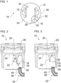
- the Figure 1 shows, purely schematically, the underside of a piston 10.
- the piston 10 can be incorporated into an internal combustion engine, for example, of a motor vehicle, in particular a commercial vehicle.
- the commercial vehicle can preferably be a truck or a bus.
- the piston 10 has two piston pin bosses 12, 14.
- the piston pin bosses 12, 14 serve to accommodate a piston pin (not shown).
- the piston pin connects the piston 10 in an articulated, in particular pivotable, manner to a connecting rod (not shown).
- the piston 10 also has an inlet channel 16.
- the inlet channel 16 opens into an inlet 28 of an inner piston cooling channel 20 (see Figure 2 ).
- the inlet channel 16 and an outlet 18 of the piston cooling channel 20 can be arranged opposite one another with respect to a central longitudinal axis of the piston 10.
- the inlet channel 16 is designed to supply a cooling fluid, for example oil, to an inlet 28 of the inner piston cooling channel 20.
- the piston cooling channel 20 extends inside the piston 10. Cooling fluid in the piston cooling channel 20 cools the piston 10 from the inside during operation. To ensure sufficient cooling of the piston 10 at different piston speeds, sufficient cooling fluid must be supplied to the piston cooling channel 20 via the inlet channel 16.
- the outlet 18 serves to drain the cooling fluid from the piston cooling channel 20, for example into a crank chamber of the internal combustion engine.
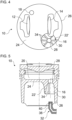
- the Figure 2 shows an eccentric section through the piston 10 in the region of the inlet channel 16.
- the inlet channel 16 is partially formed in a catcher 22.
- the catcher 22 is integrally formed on an underside 24 of the piston 10. It may also be possible to manufacture the catcher 22 as a separate component and, for example, to detachably connect it to an underside 24 of the piston 10.
- the catcher 22 can be made of the same material as the piston 10 or of a different material.
- the catcher 22 can be formed in sections by a section of a piston skirt 26.
- the catching funnel 22 can, for example, have an axial extension parallel to the piston center axis or a height H of less than 60 mm, in particular in a range between 5 mm and 40 mm.
- the height H can be measured from the underside 24 of the piston 10.
- An inlet opening of the inlet channel 16 has a larger flow cross-section than an outlet opening of the inlet channel 16.
- the inlet channel 16 opens with its outlet opening into an inlet 28 of the piston cooling channel 20.
- the inlet channel 16 tapers in the collecting funnel 22 in a direction toward the piston cooling channel 20.
- the inlet channel 16 is funnel-shaped, as shown.
- a circumferential surface 30 can enclose an acute angle (taper angle) ⁇ with a central longitudinal axis of the inlet channel 16.
- the taper angle ⁇ can in particular be greater than 0° and less than 45°, in particular between 5° and 30°.
- the enlarged inlet opening of the intake port 16 allows for a greater degree of capture of cooling fluid injected by a cooling fluid injection device 32 in a direction toward the catcher 22. Additionally, the catcher 22 protects cooling fluid within the intake port 16 from splashing and splashing fluid, such as oil, that is thrown from the crankshaft toward the piston 10. This reduces the impact on the cooling fluid within the intake port 16.
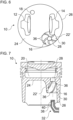
- the Figure 3 shows an alternative embodiment in which the collecting funnel 22' is designed such that the inlet channel 16 opens into the inlet 28 of the piston cooling channel 20 along its entire circumference with a radius R.
- the radius R can, for example, be less than 30 mm, in particular between 5 mm and 20 mm.
- the collecting funnel 22' of the embodiment according to Figure 3 may have a height corresponding to the height H of the catching funnel 22 of the embodiment according to Figure 2 Alternatively or additionally, the catching funnel 22' of the embodiment according to Figure 3 have a taper angle which corresponds to the taper angle ⁇ of the embodiment according to Figure 2 corresponds.
- the present application is particularly directed to promoting a cooling fluid flow within the inlet channel 16 in a direction toward the piston cooling channel 20.
- the inlet channel 16 and/or the cooling fluid injection device 32 can be specially designed, as described below by way of example.
- the surface of the circumferential surface 30 of the inlet channel 16 can be treated.
- the treatment can, in particular, reduce the surface roughness of the circumferential surface 30. This can smooth the surface of the circumferential surface 30, thus reducing cooling fluid friction of cooling fluid flowing along the circumferential surface 30 in a direction toward the piston cooling channel 20.
- the circumferential surface 30 can be polished at least in sections.
- the circumferential surface 30 of the inlet channel 16 can be at least partially coated to reduce cooling fluid friction within the inlet channel 16.
- the circumferential surface 30 can be coated with a coating that reduces the flow resistance of the cooling fluid and/or reduces the surface roughness of the circumferential surface 30.
- the coating can be a paint, for example. It is also possible for the coating to be applied, for example, by thermal spraying.
- the Figures 4 and 5 show a further exemplary embodiment for promoting the flow of cooling fluid in the inlet channel 16.
- the inlet channel 16 has a plurality of flow guide elements 34.
- the flow guide elements 34 are arranged, for example, symmetrically around a circumference of the inlet channel 16.
- the flow guide elements 34 are rectilinear.
- the flow guide elements 34 can extend completely or in sections between an inlet opening of the inlet channel 16 and an outlet opening of the inlet channel 16, which opens into the inlet 28.
- the flow guide elements 34 can help guide the cooling fluid injected into the inlet channel 16 in a direction toward the inlet 28. It is also possible to provide more or fewer flow guide elements 34 than those shown.
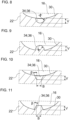
- the flow guiding elements 34 are designed as angular, in particular rectangular or trapezoidal, depressions in the peripheral surface 30 (see Figure 10 ) and/or as angular, in particular rectangular or trapezoidal, projections on the peripheral surface 30 (see Figure 11 ) are trained.
- the flow guiding elements 34 formed as depressions and/or projections can, for example, have a width B between 0.1 mm and 5 mm, as shown by way of example in the Figures 10 and 11 is shown.
- the side walls of the angular flow guide elements 34 can enclose an angle ⁇ with a normal of the circumferential surface 30, which is, for example, greater than or equal to 0° and/or less than or equal to 90°.
- the flow guide elements 34, 36 can have a height or depth V which is, for example, in a range between 0.1 mm and 5 mm.
- the Figures 6 and 7 show another embodiment for conveying the cooling fluid flow through the inlet channel 16.
- the inlet channel 16 has a plurality of flow guide elements 36.
- the flow guide elements 36 are arranged, for example, symmetrically around a circumference of the inlet channel 16.
- the flow guide elements 36 are helical (helical) around a central longitudinal axis of the inlet channel 16.
- the flow guide elements 36 can extend completely or in sections between an inlet opening of the inlet channel 16 and an outlet opening of the inlet channel 16, which opens into the inlet 28. Similar to the flow guide elements 34 according to the embodiment of Figures 4 and 5
- the flow guide elements 36 can help to guide the cooling fluid injected into the inlet channel 16 in a direction toward the inlet 28. It is also possible to provide more or fewer flow guide elements 36 than those shown.
- the flow guiding elements 36 can be designed as, in particular, rounded or angular, depressions in the peripheral surface 30 (see Figures 8 and 10 ) and/or as, in particular rounded or angular, elevations or projections on the peripheral surface 30 (see Figures 9 and 11 ) must be trained.
- cooling fluid flow in the inlet channel 16 by combining a surface treatment, a coating, at least one flow guide element 34 and/or at least one flow guide element 36.
- the cooling fluid injection device 32 can also be specially designed, as shown in the Figures 2, 3, 5 and 7 is shown by way of example.
- the cooling fluid injection device 32 can have an injection nozzle 38.
- the injection nozzle 38 can be designed such that a swirl is impressed on the cooling fluid during injection of the cooling fluid. This can stabilize the injection jet and make it less susceptible to deflections by spray and splashing fluid.
- the injection nozzle 38 can be provided with at least one helically designed swirl element 40 in order to impart a swirl to the cooling fluid during injection.
- the swirl elements 40 can be designed, for example, as depressions and/or as projections in the injection nozzle 38.
Landscapes
- Engineering & Computer Science (AREA)
- Mechanical Engineering (AREA)
- General Engineering & Computer Science (AREA)
- Chemical & Material Sciences (AREA)
- Combustion & Propulsion (AREA)
- Physics & Mathematics (AREA)
- Fluid Mechanics (AREA)
- Pistons, Piston Rings, And Cylinders (AREA)
Description
- Die Erfindung betrifft einen Kolben für eine Brennkraftmaschine.
- Zur Kühlung eines Kolbens einer Brennkraftmaschine kann ein Kolben einen inneren Kolbenkühlkanal aufweisen. Der Kolbenkühlkanal kann einen Einlass an einer Unterseite des Kolbens aufweisen. Durch den Einlass kann Kühlfluid, zum Beispiel Öl, das von einer Kühlfluideinspritzdüse in einer Richtung zu dem Einlass eingespritzt wird, in den Kolbenkühlkanal gelangen. Das Kühlfluid kann aus dem Kolbenkühlkanal durch einen Auslass an der Unterseite des Kolbens austreten.
- Aus der
DE 197 36 135 C1 ist ein flüssigkeitsgekühlter Kolben für Verbrennungsmotoren bekannt, welcher einen wenigstens teilweise ringsegmentförmigen Kühlkanal aufweist. Der Kühlkanal ist unterhalb eines Kolbenbodens in einem Kolbenoberteil ausgeformt. Der Kühlkanal weist Öffnungen zum Eintritt und Austritt der Kühlflüssigkeit auf. Die Öffnungen sind mit einem Fangtrichter ausgeformt. - Aus der
EP 2 348 207 A2 ist ferner ein Kolben bekannt, bei dem ein Einlasskanal für einen Kolbenkühlkanal vollständig in einem Kolbenschaft eines Kolbens angeordnet ist. Der Einlasskanal weist einen trichterförmigen Einlassbereich auf. - Zum weiteren Stand der Technik bezüglich Kühlfluid, das von einer Kühlfluideinspritzdüse in einer Richtung zu einem Einlasskanal eines Kolbens eingespritzt wird, wird auf die
KR 2014 0023602 A EP 1 925 805 A1 , dieJP 2007 315244 A DE 20 2006 020280 U1 , dieDE 10 2011 106379 A1 , dieDE 10 2017 113014 A1 , dieKR 2015 0099102 A DE 10 2012 211060 A , dieWO 2016/171004 A1 und dieCN 203 835 518 U hingewiesen. - Insbesondere bei hohen Geschwindigkeiten des Kolbens kann es passieren, dass sich der Fanggrad des Einlasses des Kühlfluidkanals teilweise deutlich verringert. D. h., der relative Anteil des Kühlfluids, das in den inneren Kühlfluidkanal des Kolbens gelangt, verringert sich.
- Der Erfindung liegt die Aufgabe zu Grunde, eine Kühlfluidzuführung zu einem Kolbenkühlkanal zu verbessern. Insbesondere soll auch bei hohen Kolbengeschwindigkeiten genügend Kühlfluid zu dem Kolbenkühlkanal des Kolbens zugeführt werden.
- Die Aufgabe wird gelöst durch die Merkmale gemäß dem unabhängigen Anspruch. Vorteilhafte Weiterbildungen sind in den abhängigen Ansprüchen und der Beschreibung angegeben.
- Der Kolben ist für eine Brennkraftmaschine (z. B. Hubkolben-Brennkraftmaschine) geeignet. Der Kolben weist einen inneren Kolbenkühlkanal zum Kühlen des Kolbens auf. Der Kolben weist einen Einlasskanal, der in den Kolbenkühlkanal mündet, auf. Ein Strömungsquerschnitt des Einlasskanals verjüngt sich in einer Richtung zu dem Einlass des inneren Kolbenkühlkanals zumindest abschnittsweise, insbesondere trichterförmig. Der Einlasskanal ist zusätzlich zum Fördern (z. B. Verbessern, Vergrößern) eines Kühlfluidflusses (z. B. Verringerung von Kühlfluidreibungsverlusten) zu dem Einlass des inneren Kolbenkühlkanal ausgebildet.
- Insbesondere kann das Kühlfluid Öl sein.
- Beispielsweise kann der Einlasskanal zusätzlich zu der zumindest abschnittsweisen Verjüngung Mittel (z. B. Oberflächenbehandlung, Beschichtung und/oder Strömungsführungselement(e)) zum Fördern eines Kühlfluidflusses zu dem Kolbenkühlkanal aufweisen.
- Damit kann vorzugsweise auch bei hohen Kolbengeschwindigkeiten eine ausreichende Kühlung des Kolbens gewährleistet werden. Der sich verjüngende Einlasskanal leitet eingespritztes Kühlfluid mengenmäßig verstärkt zu dem Einlass des Kolbenkühlkanal. Damit gelangt das Kühlfluid mengenmäßig verstärkt in den Kühlfluidkanal und kann dort besser die auftretenden Wärmebelastung abtransportieren und somit eine Temperatur des Kolbens reduzieren. Ferner kann vorzugsweise durch die spezielle Ausbildung des Einlasskanals zum Beispiel durch Verringerung von Kühlfluidreibungsverlusten ein Kühlfluidfluss durch den Einlasskanal in den Einlass des Kühlfluidkanals gefördert werden.
- Insbesondere kann der Einlasskanal unterhalb von einer Unterseite des Kolbens angeordnet sein. Beispielsweise kann der Einlasskanal direkt unterhalb eines Einlasses des Kolbenkühlkanals angeordnet sein.
- Es ist möglich, dass der Einlass des Kolbenkühlkanals sich in einer Unterseite des Kolbens öffnet.
- Beispielsweise kann der Kühlfluidkanal ringförmig ausgebildet sein und/oder eine Mehrzahl von Teilkanälen aufweisen. Es ist möglich, dass der Kühlfluidkanal unterhalb eines Kolbenbodens in einem Kolbenoberteil angeordnet ist.
- Zweckmäßig kann der Kolbenkühlkanal einen Auslass aufweisen. Beispielsweise kann der Auslass bezüglich einer Mittelachse des Kolbens gegenüber dem Einlass des Kühlfluidkanals angeordnet sein.
- In einem besonders bevorzugten Ausführungsbeispiel ist der Einlasskanal zum Fördern des Kühlfluidflusses im Einlasskanal zumindest abschnittsweise oberflächenbehandelt, insbesondere zur Verringerung einer Oberflächenrauheit. Vorzugsweise kann der Einlasskanal poliert sein. Damit können Kühlfluidreibungsverluste im Einlasskanal verringert und damit ein Kühlfluidfluss in den Kühlfluidkanal vergrößert werden.
- Insbesondere kann eine Umfangsfläche des Einlasskanals zumindest abschnittsweise oberflächenbehandelt sein, insbesondere zur Verringerung einer Oberflächenrauheit der Umfangsfläche. Zum Beispiel kann die Umfangsfläche zumindest abschnittsweise poliert sein.
- In einem weiteren besonders bevorzugten Ausführungsbeispiel ist der Einlasskanal zum Fördern des Kühlfluidflusses im Einlasskanal mit einer Strömungswiderstand-senkenden und/oder einer Oberflächenrauheit-verringernden Beschichtung beschichtet. Insbesondere kann die Beschichtung durch thermisches Spritzen aufgetragen sein. Auch hiermit können Kühlfluidreibungsverluste im Einlasskanal verringert und damit ein Kühlfluidfluss in den Kühlfluidkanal vergrößert werden.
- Insbesondere kann eine Umfangsfläche des Einlasskanals zumindest abschnittsweise beschichtet sein.
- Erfindungsgemäß weist der Einlasskanal zum Fördern des Kühlfluidflusses im Einlasskanal mindestens ein Strömungsführungselement zum Führen des Kühlfluids in einer Richtung zu dem Einlass des inneren Kolbenkühlkanals auf. Durch die Führung kann das Kühlfluid gezielt zu dem Einlass des inneren Kolbenkühlkanals geleitet werden. Das Kühlfluid kann schneller in den Kühlfluidkanal fließen. Ein Kühlfluidfluss in den Kühlfluidkanal kann vergrößert werden.
- In einer Weiterbildung ist das mindestens eine Strömungsführungselement als eine Nut in einer Umfangsfläche des Einlasskanals ausgebildet. Alternativ oder zusätzlich ist das mindestens eine Strömungsführungselement als ein Vorsprung, insbesondere als eine Leitfinne, an einer Umfangsfläche des Einlasskanals ausgebildet.
- Zweckmäßig kann die Nut und/oder der Vorsprung gerundet (z. B. mit einem Radius zwischen 0,1 mm und 5 mm) oder eckig (z. B. rechteckförmig, trapezförmig usw.) ausgebildet sein. Beispielsweise kann die Nut und/oder der Vorsprung eine Breite zwischen 0,1 mm und 5 mm aufweisen. Insbesondere kann eine Seitenfläche einer eckig ausgebildeten Nut und/oder eines eckig ausgebildeten Vorsprungs einen Winkel in einem Bereich zwischen 0° und 90° mit einer Normalen der Umfangsfläche einschließen.
- Zweckmäßig kann das mindestens eine Strömungsführungselement eine Höhe oder Tiefe in einem Bereich zwischen 0,1 mm und 5 mm aufweisen.
- In einem Ausführungsbeispiel erstreckt sich das mindestens eine Strömungsführungselement in einer Richtung zu dem Einlass des inneren Kolbenkühlkanals. Es ist auch möglich, dass sich das mindestens eine Strömungsführungselement zumindest abschnittsweise geradlinig und/oder zumindest abschnittsweise wendelförmig erstreckt. Somit kann das Kühlfluid gradlinig bzw. wendelförmig zu dem Einlass des inneren Kühlfluidkanals zugeführt werden.
- In einem weiteren Ausführungsbeispiel weist das mindestens eine Strömungsführungselement eine Mehrzahl von, insbesondere symmetrisch, um einen Umfang des Einlasskanals angeordneten Strömungsführungselementen auf.
- Insbesondere kann das mindestens eine Strömungsführungselement in einer Umfangsfläche des Einlasskanals eingepresst, eingeschnitten oder eingearbeitet sein.
- In einer Ausführungsvariante ist der Einlasskanal zumindest teilweise von einem Fangtrichter gebildet, der mit einer Unterseite des Kolbens verbunden ist.
- In einer Weiterbildung ist der Fangtrichter integral-einstückig mit der Unterseite des Kolbens ausgebildet oder separat ausgebildet und mit der Unterseite, insbesondere lösbar, verbunden.
- In einer weiteren Ausführungsvariante sind der Fangtrichter und die Unterseite des Kolbens aus dem gleichen Material oder aus unterschiedlichen Materialien hergestellt. Damit kann beispielsweise auf kostengünstige Materialien und/oder gut formbare oder bearbeitbare Materialien für den Fangtrichter zurückgegriffen werden.
- Beispielsweise kann der Fangtrichter eine Höhe größer als 0 mm und/oder kleiner als 60 mm, insbesondere in einem Bereich zwischen 5 mm und 40 mm, aufweisen.
- In einer Ausführungsform ist der Fangtrichter zumindest teilweise von einem Kolbenschaft gebildet. Beispielsweise kann der Kolbenschaft ein Wandsegment des Fangtrichters bilden, das mit einem weiteren, separat von dem Kolbenschaft ausgebildeten Wandsegment des Fangtrichters verbunden ist.
- In einer weiteren Ausführungsform verjüngt sich der Einlasskanal zumindest abschnittsweise in einem Winkel größer als 0° und/oder kleiner als 45°, insbesondere zwischen 5° und 30°, zu einer Längsachse des Einlasskanals. Alternativ oder zusätzlich mündet der Einlasskanal gerundet in den Einlass des Kolbenkühlkanals, insbesondere mit einem Radius größer als 0 mm und/oder kleiner als 30 mm, vorzugsweise zwischen 5 mm und 20 mm.
- Die Erfindung betrifft auch eine Kühlfluideinspritzeinrichtung, die dazu ausgebildet ist, das Kühlfluid mit einem Drall (z. B. wendelförmige Strömung und/oder Rotation um eine Achse des Kühlfluidstrahls) einzuspritzen. Der Drall kann den in einer Richtung zu einer Unterseite eines Kolbens eingespritzten Kühlfluidstrahl stabilisieren. Der so stabilisierte Kühlfluidstrahl wird weniger durch Spritz- und Panschfluid in Kurbelgehäuse beeinträchtigt. Damit kann der zu einem Kühlfluidkanal des Kolbens zugeführte Kühlfluidfluss mengenmäßig vergrößert werden.
- Erfindungsgemäß ist die Kühlfluideinspritzeinrichtung in einer Vorrichtung umfasst sein, die einen Kolben wie hierin offenbart aufweist. Die Kühlfluideinspritzeinrichtung kann auf eine Einlassöffnung des Einlasskanals gerichtet sein.
- Insbesondere kann die Kühlfluideinspritzeinrichtung an einem Kurbelgehäuse der Brennkraftmaschine, insbesondere fest, angebracht sein. Es ist möglich, dass die Kühlfluideinspritzeinrichtung fluidisch mit einer Kühlfluidpumpe verbunden ist, die Kühlfluid zu der Kühlfluideinspritzeinrichtung fördert.
- In einer Weiterbildung weist die Kühlfluideinspritzeinrichtung eine Einspritzdüse mit mindestens einem Drallelement, insbesondere eine wendelförmige Nut und/oder ein wendelförmiger Vorsprung, das dazu ausgebildet ist, dem Kühlfluid einen Drall aufzuprägen, auf. Insbesondere kann das mindestens eine Drallelement in einem Kanal der Einspritzdüse eingepresst, eingeschnitten oder eingearbeitet sein.
- Die Erfindung ist auch auf ein Kraftfahrzeug, insbesondere ein Nutzfahrzeug, mit einem Kolben wie hierin offenbart oder einer Vorrichtung wie hierin offenbart gerichtet.
- Es ist beispielsweise auch möglich, den Kolben und/oder die Vorrichtung wie hierin offenbart für Personenkraftwagen, Großmotoren, geländegängige Fahrzeuge, stationäre Motoren, Marinemotoren usw. zu verwenden.
- Die zuvor beschriebenen bevorzugten Ausführungsformen und Merkmale der Erfindung sind beliebig miteinander kombinierbar. Weitere Einzelheiten und Vorteile der Erfindung werden im Folgenden unter Bezug auf die beigefügten Zeichnungen beschrieben. Es zeigen:
- Figur 1
- eine schematische Ansicht einer Unterseite eines Kolbens gemäß einem Ausführungsbeispiel;
- Figur 2
- eine Schnittansicht durch den beispielhaften Kolben und eine Kühlfluideinspritzeinrichtung;
- Figur 3
- eine Schnittansicht durch einen Kolben gemäß einem weiteren Ausführungsbeispiel und eine Kühlfluideinspritzeinrichtung;
- Figur 4
- eine schematische Ansicht einer Unterseite eines Kolbens gemäß einem weiteren Ausführungsbeispiel;
- Figur 5
- eine Schnittansicht durch den beispielhaften Kolben von
Figur 4 und eine Kühlfluideinspritzeinrichtung; - Figur 6
- eine schematische Ansicht einer Unterseite eines Kolbens gemäß einem weiteren anderen Ausführungsbeispiel;
- Figur 7
- eine Schnittansicht durch den beispielhaften Kolben von
Figur 6 und eine Kühlfluideinspritzeinrichtung; - Figur 8
- einen Ausschnitt einer Schnittansicht durch einen beispielhaften Fangtrichter;
- Figur 9
- einen Ausschnitt einer Schnittansicht durch einen weiteren beispielhaften Fangtrichter;
- Figur 10
- einen Ausschnitt einer Schnittansicht durch einen weiteren beispielhaften Fangtrichter; und
- Figur 11
- einen Ausschnitt einer Schnittansicht durch einen weiteren beispielhaften Fangtrichter.
- Die in den Figuren gezeigten Ausführungsformen stimmen zumindest teilweise überein, so dass ähnliche oder identische Teile mit den gleichen Bezugszeichen versehen sind und zu deren Erläuterung auch auf die Beschreibung der anderen Ausführungsformen bzw. Figuren verwiesen wird, um Wiederholungen zu vermeiden.
- Die
Figur 1 zeigt rein schematisch eine Unterseite eines Kolbens 10. Der Kolben 10 kann in einer Brennkraftmaschine beispielsweise eines Kraftfahrzeugs, insbesondere Nutzfahrzeugs, umfasst sein. Das Nutzfahrzeug kann vorzugsweise ein Lastkraftwagen oder ein Omnibus sein. - Der Kolben 10 weist zwei Kolbenbolzenaugen 12, 14 auf. Die Kolbenbolzenaugen 12, 14 dienen zur Aufnahme eines Kolbenbolzens (nicht dargestellt). Der Kolbenbolzen verbindet den Kolben 10 gelenkig, insbesondere schwenkbar, mit einem Pleuel (nicht dargestellt).
- Der Kolben 10 weist zudem einen Einlasskanal 16 auf. Der Einlasskanal 16 mündet in einen Einlass 28 eines inneren Kolbenkühlkanals 20 (siehe
Figur 2 ). Der Einlasskanal 16 und ein Auslass 18 des Kolbenkühlkanals 20 können einander gegenüberliegend bezüglich einer Mittellängsachse des Kolbens 10 angeordnet sein. Der Einlasskanal 16 ist dazu ausgebildet, ein Kühlfluid, zum Beispiel Öl, zu einem Einlass 28 des inneren Kolbenkühlkanals 20 zuzuführen. Der Kolbenkühlkanal 20 erstreckt sich im Inneren des Kolbens 10. Kühlfluid im Kolbenkühlkanal 20 kühlt den Kolben 10 während des Betriebs von innen. Um eine ausreichende Kühlung des Kolbens 10 bei unterschiedlichen Kolbengeschwindigkeit zu gewährleisten, muss genügend Kühlfluid über den Einlasskanal 16 zu dem Kolbenkühlkanal 20 zugeführt werden. Der Auslass 18 dient zum Ablassen des Kühlfluids aus dem Kolbenkühlkanal 20, zum Beispiel in eine Kurbelkammer der Brennkraftmaschine. - Die
Figur 2 zeigt einen exzentrischen Schnitt durch den Kolben 10 im Bereich des Einlasskanals 16. Wie dargestellt ist, ist der Einlasskanal 16 teilweise in einem Fangtrichter 22 ausgebildet. Der Fangtrichter 22 ist an einer Unterseite 24 des Kolbens 10 angeformt. Es kann auch möglich sein, den Fangtrichter 22 als ein separates Bauteil zu fertigen und beispielsweise lösbar mit einer Unterseite 24 des Kolbens 10 zu verbinden. Der Fangtrichter 22 kann aus dem gleichen Material wie der Kolben 10 oder aus einem anderen Material hergestellt sein. Der Fangtrichter 22 kann abschnittsweise von einem Abschnitt eines Kolbenschafts 26 gebildet sein. - Der Fangtrichter 22 kann beispielsweise eine Axialerstreckung parallel zur Kolbenmittelachse bzw. Höhe H von kleiner als 60 mm, insbesondere in einem Bereich zwischen 5 mm und 40 mm, aufweisen. Die Höhe H kann ausgehend von der Unterseite 24 des Kolbens 10 gemessen sein.
- Eine Einlassöffnung des Einlasskanals 16 weist einen größeren Strömungsquerschnitt auf als eine Auslassöffnung des Einlasskanals 16. Der Einlasskanal 16 mündet mit dessen Auslassöffnung in einen Einlass 28 des Kolbenkühlkanals 20. Der Einlasskanal 16 verjüngt sich im Fangtrichter 22 in einer Richtung zu dem Kolbenkühlkanal 20. Insbesondere ist der Einlasskanal 16, wie dargestellt ist, trichterförmig ausgebildet. Insbesondere kann eine Umfangsfläche 30 einen spitzen Winkel (Verjüngungswinkel) α mit einer Mittelängsachse des Einlasskanals 16 einschließen. Der Verjüngungswinkel α kann insbesondere größer als 0° und kleiner als 45°, insbesondere zwischen 5° und 30°, sein.
- Die vergrößerte Einlassöffnung des Einlasskanals 16 ermöglicht einen vergrößerten Fanggrad von Kühlfluid, das von einer Kühlfluideinspritzeinrichtung 32 in einer Richtung zu dem Fangtrichter 22 eingespritzt wird. Zusätzlich schützt der Fangtrichter 22 Kühlfluid innerhalb des Einlasskanals 16 vor Spritz- und Panschfluid, zum Beispiel Öl, das beispielsweise von der Kurbelwelle in Richtung zu dem Kolben 10 geschleudert wird. Damit wird das Kühlfluid innerhalb des Einlasskanals 16 weniger beeinflusst.
- Die
Figur 3 zeigt ein alternatives Ausführungsbeispiel, bei dem der Fangtrichter 22' so ausgebildet ist, dass der Einlasskanal 16 entlang seines gesamten Umfangs mit einem Radius R in den Einlass 28 des Kolbenkühlkanals 20 mündet. Der Radius R kann beispielsweise kleiner als 30 mm, insbesondere zwischen 5 mm und 20 mm, sein. Der Fangtrichter 22' des Ausführungsbeispiels gemäßFigur 3 kann eine Höhe aufweisen, die der Höhe H des Fangtrichters 22 des Ausführungsbeispiels gemäßFigur 2 entspricht. Alternativ oder zusätzlich kann der Fangtrichter 22' des Ausführungsbeispiels gemäßFigur 3 einen Verjüngungswinkel aufweisen, der dem Verjüngungswinkel α des Ausführungsbeispiels gemäßFigur 2 entspricht. - Die vorliegende Anmeldung ist insbesondere darauf gerichtet, einen Kühlfluidfluss innerhalb des Einlasskanals 16 in einer Richtung zu dem Kolbenkühlkanal 20 zu fördern. Um dies zu erreichen, kann der Einlasskanal 16 und/oder die Kühlfluideinspritzeinrichtung 32 speziell ausgebildet sein, wie nachfolgend beispielhaft beschrieben ist.
- Um beispielsweise eine Kühlfluidreibung innerhalb des Einlasskanals 16 zu verringern, kann die Oberfläche der Umfangsfläche 30 des Einlasskanals 16 behandelt sein. Die Behandlung kann insbesondere eine Verringerung einer Oberflächenrauheit der Umfangsfläche 30 bewirken. Damit kann die Oberfläche der Umfangsfläche 30 geglättet werden und somit ein Kühlfluidreibung von Kühlfluid, das entlang der Umfangsfläche 30 in einer Richtung zu dem Kolbenkühlkanal 20 fließt, verringert werden. Beispielsweise kann die Umfangsfläche 30 zumindest abschnittsweise poliert sein.
- Es ist beispielsweise auch möglich, dass die Umfangsfläche 30 des Einlasskanals 16 zumindest teilweise beschichtet ist, um eine Kühlfluidreibung innerhalb des Einlasskanals 16 zu verringern. Beispielsweise kann die Umfangsfläche 30 mit einer den Strömungswiderstand des Kühlfluids senkenden und/oder eine Oberflächenrauheit der Umfangsfläche 30 verringernden Beschichtung beschichtet sein. Die Beschichtung kann zum Beispiel ein Lack sein. Es ist auch möglich, dass die Beschichtung bspw. durch thermisches Spritzen aufgetragen wird.
- Die
Figuren 4 und 5 zeigen ein weiteres Ausführungsbeispiel zum Fördern des Kühlfluidflusses im Einlasskanal 16. Hier weist der Einlasskanal 16 mehrere Strömungsführungselemente 34 auf. Die Strömungsführungselement 34 sind um einen Umfang des Einlasskanals 16 beispielsweise symmetrisch angeordnet. Die Strömungsführungselemente 34 sind gradlinig. Die Strömungsführungselemente 34 können sich vollständig oder abschnittsweise zwischen einer Einlassöffnung des Einlasskanals 16 und eine Auslassöffnung des Einlasskanals 16, die in den Einlass 28 mündet, erstrecken. Die Strömungsführungselemente 34 können dabei helfen, das in den Einlasskanal 16 eingespritzte Kühlfluid in einer Richtung zu dem Einlass 28 zu führen. Es ist auch möglich, dass mehr oder weniger als die dargestellten Strömungsführungselemente 34 vorgesehen sind. - Wie in der
Figur 8 dargestellt ist, können die Strömungsführungselemente 34 als, insbesondere gerundete, Vertiefungen/Nuten in der Umfangsfläche 30 ausgebildet sein. Wie in derFigur 9 dargestellt ist, können die Strömungsführungselemente 34 alternativ oder zusätzlich auch als, insbesondere gerundete, Vorsprünge an der Umfangsfläche 30 ausgebildet sein. Ein Radius K der Strömungsführungselemente 34 kann beispielsweise zwischen 0,1 mm und 5 mm sein. - Es ist auch möglich, dass die Strömungsführungselemente 34 als eckige, insbesondere rechteckförmige oder trapezförmige, Vertiefungen in der Umfangsfläche 30 (siehe
Figur 10 ) und/oder als eckige, insbesondere rechteckförmige oder trapezförmige, Vorsprünge an der Umfangsfläche 30 (sieheFigur 11 ) ausgebildet sind. - Die als Vertiefungen und/oder Vorsprünge ausgebildeten Strömungsführungselemente 34 können bspw. eine Breite B zwischen 0,1 mm und 5 mm aufweisen, wie beispielhaft in den
Figuren 10 und 11 dargestellt ist. - Die Seitenwände der eckig ausgebildeten Strömungsführungselemente 34 (siehe
Figuren 10 und 11 ) können mit einer Normalen der Umfangsfläche 30 einen Winkel β einschließen, der beispielsweise größer oder gleich 0° und/oder kleiner oder gleich 90° ist. - Wie in den
Figuren 8 bis 11 dargestellt ist, können die Strömungsführungselemente 34, 36 eine Höhe oder Tiefe V aufweisen, die beispielsweise in einem Bereich zwischen 0,1 mm und 5 mm liegt. - Die
Figuren 6 und 7 zeigen ein weiteres anderes Ausführungsbeispiel zum Fördern des Kühlfluidflusses durch den Einlasskanal 16. Der Einlasskanal 16 weist mehrere Strömungsführungselemente 36 auf. Die Strömungsführungselemente 36 sind um einen Umfang des Einlasskanals 16 beispielsweise symmetrisch angeordnet. Die Strömungsführungselemente 36 sind wendelförmig (helixförmig) um eine Mittellängsachse des Einlasskanals 16 ausgebildet. Die Strömungsführungselemente 36 können sich vollständig oder abschnittsweise zwischen einer Einlassöffnung des Einlasskanals 16 und eine Auslassöffnung das Einlasskanals 16, die in den Einlass 28 mündet, erstrecken. Ähnlich zu den Strömungsführungselementen 34 gemäß dem Ausführungsbeispiel derFiguren 4 und 5 können die Strömungsführungselemente 36 dabei helfen, das in den Einlasskanal 16 eingespritzte Kühlfluid in einer Richtung zu dem Einlass 28 zu führen. Es ist auch möglich, dass mehr oder weniger als die dargestellten Strömungsführungselemente 36 vorgesehen sind. - Die Strömungsführungselemente 36 können als, insbesondere gerundete oder eckige, Vertiefungen in der Umfangsfläche 30 (siehe
Figuren 8 und 10 ) und/oder als, insbesondere gerundete oder eckige, Erhebungen bzw. Vorsprünge an der Umfangsfläche 30 (sieheFiguren 9 und 11 ) ausgebildet sein. - In den
Figuren 5 und7 sind die Strömungsführungselemente 34 bzw. 36 in Kombination mit dem Fangtrichter 22', der unter Bezugnahme auf dieFigur 3 beschrieben wurde, beschrieben. Es ist selbstverständlich auch möglich, die Strömungsführungselemente 34 bzw. 36 beispielsweise in den Fangtrichter 22, der unter Bezugnahme auf dieFigur 2 beschrieben wurde, zu integrieren. - Es ist auch möglich, den Kühlfluidfluss im Einlasskanal 16 durch Kombination einer Oberflächenbehandlung, einer Beschichtung, mindestens eines Strömungsführungselemente 34 und/oder mindestens eines Strömungsführungselemente 36 zu fördern.
- Zusätzlich zu der Förderung des Kühlfluidflusses im Einlasskanal 16 kann auch die Kühlfluideinspritzeinrichtung 32 speziell ausgebildet sein, wie in den
Figuren 2, 3, 5 und7 beispielhaft dargestellt ist. Die Kühlfluideinspritzeinrichtung 32 kann eine Einspritzdüse 38 aufweisen. Die Einspritzdüse 38 kann so ausgebildet sein, dass beim Einspritzen des Kühlfluids ein Drall auf das Kühlfluid aufgeprägt wird. Dadurch kann der Einspritzstrahl stabilisiert und weniger anfällig für Ablenkungen durch Spritz- und Panschfluid sein. Insbesondere kann die Einspritzdüse 38 mit mindestens einem wendelförmig ausgebildeten Drallelement 40 versehen sein, um beim Einspritzen einen Drall auf das Kühlfluid aufzuprägen. Die Drallelemente 40 können beispielsweise als Vertiefungen und/oder als Vorsprünge in der Einspritzdüse 38 ausgebildet sein. -
- 10
- Kolben
- 12
- Kolbenbolzenauge
- 14
- Kolbenbolzenauge
- 16
- Einlasskanal
- 18
- Auslass
- 20
- Kolbenkühlkanal
- 22
- Fangtrichter
- 24
- Unterseite
- 26
- Kolbenschaft
- 28
- Einlass
- 30
- Umfangsfläche
- 32
- Kühlfluideinspritzeinrichtung
- 34
- Strömungsführungselement
- 36
- Strömungsführungselement
- 38
- Einspritzdüse
- 40
- Drallelement
- α
- Verjüngungswinkel
- β
- Strömungselementwinkel
- B
- Breite
- H
- Höhe
- K
- Radius
- R
- Radius
- V
- Höhe / Tiefe
Claims (12)
- Kolben (10) für eine Brennkraftmaschine, aufweisend:einen inneren Kolbenkühlkanal (20) zum Kühlen des Kolbens (10); undeinen Einlasskanal (16), der in einen Einlass (28) des Kolbenkühlkanals (20) mündet, wobei sich ein Strömungsquerschnitt des Einlasskanals (16) in einer Richtung zu dem Einlass (28) des inneren Kolbenkühlkanals (20) zumindest abschnittsweise, insbesondere trichterförmig, verjüngt und der Einlasskanal (16) zusätzlich zum Fördern eines Kühlfluidflusses zu dem Einlass (28) des inneren Kolbenkühlkanals (20) ausgebildet ist,wobei:der Einlasskanal (16) zumindest abschnittsweise zur Verringerung einer Oberflächenrauheit oberflächenbehandelt, vorzugsweise poliert, ist und/oder der Einlasskanal (16) mit einer Strömungswiderstand-senkenden und/oder einer Oberflächenrauheit-verringernden Beschichtung beschichtet ist, insbesondere durch thermisches Spritzen; undder Einlasskanal (16) mindestens ein Strömungsführungselement (34; 36) zum Führen des Kühlfluids in einer Richtung zu dem Einlass (18) des Kolbenkühlkanals (20) aufweist.
- Kolben (10) nach Anspruch 1, wobei:das mindestens eine Strömungsführungselement (34; 36) als eine Nut in einer Umfangsfläche (30) des Einlasskanals (16) ausgebildet ist; und/oderdas mindestens eine Strömungsführungselement (34; 36) als ein Vorsprung, insbesondere als eine Leitfinne, an einer Umfangsfläche (30) des Einlasskanals (16) ausgebildet ist.
- Kolben (10) nach Anspruch 1 oder Anspruch 2, wobei:das mindestens eine Strömungsführungselement (34; 36) sich in einer Richtung zu dem Einlass (28) des inneren Kolbenkühlkanals (20) erstreckt; und/odersich das mindestens eine Strömungsführungselement (34; 36) zumindest abschnittsweise geradlinig und/oder zumindest abschnittsweise wendelförmig erstreckt.
- Kolben (10) nach einem der Ansprüche 1 bis 3, wobei:
das mindestens eine Strömungsführungselement (34; 36) eine Mehrzahl von, insbesondere symmetrisch, um einen Umfang des Einlasskanals (16) angeordneten Strömungsführungselementen (34; 36) aufweist. - Kolben (10) nach einem der vorherigen Ansprüche, wobei:
der Einlasskanal (16) zumindest teilweise von einem Fangtrichter (22) gebildet ist, der mit einer Unterseite (24) des Kolbens (10) verbunden ist. - Kolben (10) nach Anspruch 5, wobei:
der Fangtrichter (22) integral-einstückig mit der Unterseite (24) des Kolbens (10) ausgebildet oder separat ausgebildet und mit der Unterseite (24), insbesondere lösbar, verbunden ist. - Kolben (10) nach Anspruch 5 oder Anspruch 6, wobei:der Fangtrichter (22) und die Unterseite (24) des Kolbens (10) aus dem gleichen Material oder aus unterschiedlichen Materialien hergestellt sind; und/oderder Fangtrichter (22) eine Höhe (H) größer als 0 mm und/oder kleiner als 60 mm, insbesondere in einem Bereich zwischen 5 mm und 40 mm, aufweist.
- Kolben (10) nach einem der Ansprüche 5 bis 7, wobei:
der Fangtrichter (22) zumindest teilweise von einem Kolbenschaft (26) gebildet ist. - Kolben (10) nach einem der vorherigen Ansprüche, wobei:sich der Einlasskanal (16) zumindest abschnittsweise in einem Winkel (α) größer als 0° und/oder kleiner als 45°, insbesondere zwischen 5° und 30°, zu einer Längsachse des Einlasskanals (16) verjüngt; und/oderder Einlasskanal (16) gerundet in den Einlass (28) des Kolbenkühlkanals (20) mündet, insbesondere mit einem Radius (R) größer als 0 mm und/oder kleiner als 30 mm, vorzugsweise zwischen 5 mm und 20 mm.
- Vorrichtung, aufweisendeinen Kolben (10) nach einem der vorherigen Ansprüche; undeine Kühlfluideinspritzeinrichtung (32), die auf eine Einlassöffnung des Einlasskanals (16) gerichtet und dazu ausgebildet ist, das Kühlfluid mit einem Drall einzuspritzen.
- Vorrichtung nach Anspruch 10, wobei:
die Kühlfluideinspritzeinrichtung (32) eine Einspritzdüse (38) mit mindestens einem Drallelement (40), insbesondere eine wendelförmige Nut und/oder ein wendelförmiger Vorsprung, das dazu ausgebildet ist, dem Kühlfluid einen Drall aufzuprägen, aufweist. - Kraftfahrzeug, insbesondere Nutzfahrzeug, mit einem Kolben (10) nach einem der Ansprüche 1 bis 9 oder einer Vorrichtung nach Anspruch 10 oder 11.
Applications Claiming Priority (1)
| Application Number | Priority Date | Filing Date | Title |
|---|---|---|---|
| DE102018100336.6A DE102018100336A1 (de) | 2018-01-09 | 2018-01-09 | Kolben für eine Brennkraftmaschine |
Publications (3)
| Publication Number | Publication Date |
|---|---|
| EP3508714A1 EP3508714A1 (de) | 2019-07-10 |
| EP3508714B1 EP3508714B1 (de) | 2022-03-30 |
| EP3508714B2 true EP3508714B2 (de) | 2025-04-02 |
Family
ID=64959205
Family Applications (1)
| Application Number | Title | Priority Date | Filing Date |
|---|---|---|---|
| EP19150136.0A Active EP3508714B2 (de) | 2018-01-09 | 2019-01-03 | Kolben für eine brennkraftmaschine |
Country Status (2)
| Country | Link |
|---|---|
| EP (1) | EP3508714B2 (de) |
| DE (1) | DE102018100336A1 (de) |
Family Cites Families (17)
| Publication number | Priority date | Publication date | Assignee | Title |
|---|---|---|---|---|
| DE19736135C1 (de) | 1997-08-20 | 1998-10-29 | Daimler Benz Ag | Flüssigkeitsgekühlter Kolben für Verbrennungsmotoren |
| JP2005048650A (ja) * | 2003-07-28 | 2005-02-24 | Nissan Diesel Motor Co Ltd | 内燃機関用ピストン |
| JP2007315244A (ja) * | 2006-05-24 | 2007-12-06 | Toyota Industries Corp | 内燃機関のピストン冷却装置 |
| DE102006056013A1 (de) * | 2006-11-28 | 2008-05-29 | Ks Kolbenschmidt Gmbh | Kühlkanalkolben |
| DE102006056012A1 (de) * | 2006-11-28 | 2008-05-29 | Ks Kolbenschmidt Gmbh | Variabel gestalteter Kühlkanal für einen Kolben |
| DE102008035698A1 (de) | 2008-07-30 | 2010-02-04 | Mahle International Gmbh | Verfahren zur Herstellung eines Kolbens oder Kolbenteils |
| KR101417117B1 (ko) | 2008-10-22 | 2014-08-07 | 두산인프라코어 주식회사 | 피스톤 냉각 장치 |
| DE102011106379A1 (de) * | 2011-07-04 | 2013-01-10 | Mahle International Gmbh | Kolben für einen Verbrennungsmotor |
| DE102012211060A1 (de) * | 2012-06-27 | 2014-04-17 | Bayerische Motoren Werke Aktiengesellschaft | Kolben für eine Hubkolben-Brennkraftmaschine |
| KR20140023602A (ko) * | 2012-08-16 | 2014-02-27 | 현대자동차주식회사 | 오일 갤러리의 냉각 기능 향상을 위한 원통형 회전 구조물을 갖춘 피스톤 |
| JP6356704B2 (ja) * | 2013-03-05 | 2018-07-11 | フェデラル−モーグル・リミテッド・ライアビリティ・カンパニーFederal−Mogul Llc | デポジット防止コーティングを伴うピストンおよびその構築方法 |
| KR20150099102A (ko) * | 2014-02-21 | 2015-08-31 | 두산인프라코어 주식회사 | 엔진의 피스톤 |
| CN203835518U (zh) * | 2014-02-28 | 2014-09-17 | 北汽福田汽车股份有限公司 | 一种冷却液喷嘴总成及发动机 |
| DE102014219821A1 (de) | 2014-09-30 | 2016-03-31 | Siemens Aktiengesellschaft | Rückführstufe |
| DE102015002322A1 (de) * | 2015-02-26 | 2016-09-01 | Mahle International Gmbh | Kolben für einen Verbrennungsmotor |
| JP6460333B2 (ja) * | 2015-04-23 | 2019-01-30 | 日立オートモティブシステムズ株式会社 | 内燃機関のピストンおよび内燃機関のピストンの表面処理方法 |
| EP3468735B1 (de) * | 2016-06-13 | 2024-05-15 | KS Large Bore Pistons Germany GmbH | Kühlkanalöffnung durch zirkularfräsoperation |
-
2018
- 2018-01-09 DE DE102018100336.6A patent/DE102018100336A1/de active Pending
-
2019
- 2019-01-03 EP EP19150136.0A patent/EP3508714B2/de active Active
Also Published As
| Publication number | Publication date |
|---|---|
| EP3508714A1 (de) | 2019-07-10 |
| EP3508714B1 (de) | 2022-03-30 |
| DE102018100336A1 (de) | 2019-07-11 |
Similar Documents
| Publication | Publication Date | Title |
|---|---|---|
| DE102007061124B4 (de) | Gestaltung der oberen Fase eines Kolbens zur Minderung von Geräusch und Reibung | |
| EP2304210B1 (de) | Reibgeschweisster stahlkolben mit optimiertem kühlkanal | |
| DE19618625C1 (de) | Flüssigkeitsgekühlter Kolben für Verbrennungsmotoren | |
| EP2142323B1 (de) | Giesskern zur bildung eines kühlkanals in einem giesstechnisch hergestellten kolben | |
| DE112007001562T5 (de) | Kühlmittelkanalventilationsbaugruppe für einen Kolben | |
| EP3339617B1 (de) | Zylindergehäuse, verfahren zur herstellung eines zylindergehäuses und giesskern | |
| WO1995015433A1 (de) | Hubkolben aus insbesondere leichtmetall für verbrennungsmotoren | |
| EP3502493B1 (de) | Vorrichtung und verfahren zum schmieren eines pleuellagers | |
| EP3502494B1 (de) | Vorrichtung zum schmieren eines pleuellagers | |
| EP2622195A1 (de) | Brennkraftmaschine mit einem zylindergehäuse aus leichtmetallguss und mit zylinderlaufbuchsen aus rauguss | |
| DE112016005765T5 (de) | Kolben für einen Verbrennungsmotor | |
| DE202006020280U1 (de) | Kühlkanalkolben | |
| DE102017204316A1 (de) | Verbrennungsmotor | |
| EP3508714B2 (de) | Kolben für eine brennkraftmaschine | |
| DE102016100411A1 (de) | Hubkolbenvorrichtung sowie Brennkraftmaschine mit einer solchen Hubkolbenvorrichtung | |
| WO2016173690A1 (de) | Kolben für eine hubkolben-verbrennungskraftmaschine | |
| EP3411585B1 (de) | Kolben aus stahl- oder grauguss für einen verbrennungsmotor und verfahren zur herstellung eines kolbens durch stahl- oder grauguss | |
| DE10126493B4 (de) | Kolben mit zu den Hauptachsen geneigtem Kühlkanal | |
| DE102015009568B4 (de) | Brennkraftmaschine mit einer Steuereinrichtung zur gezielten Ansteuerung einer Kolbenkühldüse oder eines Kolbenkühlkanals sowie Verfahren zum Betreiben einer Brennkraftmaschine | |
| EP3502453B1 (de) | Kolben für eine hubkolben-verbrennungskraftmaschine | |
| DE3141070C2 (de) | ||
| AT524215B1 (de) | Brennkraftmaschine mit Zylinderlaufbuchse mit integriertem Kühlkanal | |
| AT526527B1 (de) | Flüssigkeitsgekühlte Brennkraftmaschine | |
| DE102021133609B3 (de) | Kolben mit funktionsoptimierten Kolbenkühlung | |
| DE102017201137A1 (de) | Kolben für einen Verbrennungsmotor |
Legal Events
| Date | Code | Title | Description |
|---|---|---|---|
| PUAI | Public reference made under article 153(3) epc to a published international application that has entered the european phase |
Free format text: ORIGINAL CODE: 0009012 |
|
| STAA | Information on the status of an ep patent application or granted ep patent |
Free format text: STATUS: THE APPLICATION HAS BEEN PUBLISHED |
|
| AK | Designated contracting states |
Kind code of ref document: A1 Designated state(s): AL AT BE BG CH CY CZ DE DK EE ES FI FR GB GR HR HU IE IS IT LI LT LU LV MC MK MT NL NO PL PT RO RS SE SI SK SM TR |
|
| AX | Request for extension of the european patent |
Extension state: BA ME |
|
| RAP1 | Party data changed (applicant data changed or rights of an application transferred) |
Owner name: MAN TRUCK & BUS SE |
|
| STAA | Information on the status of an ep patent application or granted ep patent |
Free format text: STATUS: REQUEST FOR EXAMINATION WAS MADE |
|
| 17P | Request for examination filed |
Effective date: 20200110 |
|
| RBV | Designated contracting states (corrected) |
Designated state(s): AL AT BE BG CH CY CZ DE DK EE ES FI FR GB GR HR HU IE IS IT LI LT LU LV MC MK MT NL NO PL PT RO RS SE SI SK SM TR |
|
| GRAP | Despatch of communication of intention to grant a patent |
Free format text: ORIGINAL CODE: EPIDOSNIGR1 |
|
| STAA | Information on the status of an ep patent application or granted ep patent |
Free format text: STATUS: GRANT OF PATENT IS INTENDED |
|
| INTG | Intention to grant announced |
Effective date: 20211210 |
|
| GRAS | Grant fee paid |
Free format text: ORIGINAL CODE: EPIDOSNIGR3 |
|
| GRAA | (expected) grant |
Free format text: ORIGINAL CODE: 0009210 |
|
| STAA | Information on the status of an ep patent application or granted ep patent |
Free format text: STATUS: THE PATENT HAS BEEN GRANTED |
|
| AK | Designated contracting states |
Kind code of ref document: B1 Designated state(s): AL AT BE BG CH CY CZ DE DK EE ES FI FR GB GR HR HU IE IS IT LI LT LU LV MC MK MT NL NO PL PT RO RS SE SI SK SM TR |
|
| REG | Reference to a national code |
Ref country code: GB Ref legal event code: FG4D Free format text: NOT ENGLISH |
|
| REG | Reference to a national code |
Ref country code: CH Ref legal event code: EP |
|
| REG | Reference to a national code |
Ref country code: DE Ref legal event code: R096 Ref document number: 502019003825 Country of ref document: DE |
|
| REG | Reference to a national code |
Ref country code: AT Ref legal event code: REF Ref document number: 1479406 Country of ref document: AT Kind code of ref document: T Effective date: 20220415 |
|
| REG | Reference to a national code |
Ref country code: IE Ref legal event code: FG4D Free format text: LANGUAGE OF EP DOCUMENT: GERMAN |
|
| REG | Reference to a national code |
Ref country code: NL Ref legal event code: FP |
|
| REG | Reference to a national code |
Ref country code: SE Ref legal event code: TRGR |
|
| REG | Reference to a national code |
Ref country code: LT Ref legal event code: MG9D |
|
| PG25 | Lapsed in a contracting state [announced via postgrant information from national office to epo] |
Ref country code: RS Free format text: LAPSE BECAUSE OF FAILURE TO SUBMIT A TRANSLATION OF THE DESCRIPTION OR TO PAY THE FEE WITHIN THE PRESCRIBED TIME-LIMIT Effective date: 20220330 Ref country code: NO Free format text: LAPSE BECAUSE OF FAILURE TO SUBMIT A TRANSLATION OF THE DESCRIPTION OR TO PAY THE FEE WITHIN THE PRESCRIBED TIME-LIMIT Effective date: 20220630 Ref country code: LT Free format text: LAPSE BECAUSE OF FAILURE TO SUBMIT A TRANSLATION OF THE DESCRIPTION OR TO PAY THE FEE WITHIN THE PRESCRIBED TIME-LIMIT Effective date: 20220330 Ref country code: HR Free format text: LAPSE BECAUSE OF FAILURE TO SUBMIT A TRANSLATION OF THE DESCRIPTION OR TO PAY THE FEE WITHIN THE PRESCRIBED TIME-LIMIT Effective date: 20220330 Ref country code: BG Free format text: LAPSE BECAUSE OF FAILURE TO SUBMIT A TRANSLATION OF THE DESCRIPTION OR TO PAY THE FEE WITHIN THE PRESCRIBED TIME-LIMIT Effective date: 20220630 |
|
| PG25 | Lapsed in a contracting state [announced via postgrant information from national office to epo] |
Ref country code: LV Free format text: LAPSE BECAUSE OF FAILURE TO SUBMIT A TRANSLATION OF THE DESCRIPTION OR TO PAY THE FEE WITHIN THE PRESCRIBED TIME-LIMIT Effective date: 20220330 Ref country code: GR Free format text: LAPSE BECAUSE OF FAILURE TO SUBMIT A TRANSLATION OF THE DESCRIPTION OR TO PAY THE FEE WITHIN THE PRESCRIBED TIME-LIMIT Effective date: 20220701 Ref country code: FI Free format text: LAPSE BECAUSE OF FAILURE TO SUBMIT A TRANSLATION OF THE DESCRIPTION OR TO PAY THE FEE WITHIN THE PRESCRIBED TIME-LIMIT Effective date: 20220330 |
|
| PG25 | Lapsed in a contracting state [announced via postgrant information from national office to epo] |
Ref country code: SM Free format text: LAPSE BECAUSE OF FAILURE TO SUBMIT A TRANSLATION OF THE DESCRIPTION OR TO PAY THE FEE WITHIN THE PRESCRIBED TIME-LIMIT Effective date: 20220330 Ref country code: SK Free format text: LAPSE BECAUSE OF FAILURE TO SUBMIT A TRANSLATION OF THE DESCRIPTION OR TO PAY THE FEE WITHIN THE PRESCRIBED TIME-LIMIT Effective date: 20220330 Ref country code: RO Free format text: LAPSE BECAUSE OF FAILURE TO SUBMIT A TRANSLATION OF THE DESCRIPTION OR TO PAY THE FEE WITHIN THE PRESCRIBED TIME-LIMIT Effective date: 20220330 Ref country code: PT Free format text: LAPSE BECAUSE OF FAILURE TO SUBMIT A TRANSLATION OF THE DESCRIPTION OR TO PAY THE FEE WITHIN THE PRESCRIBED TIME-LIMIT Effective date: 20220801 Ref country code: ES Free format text: LAPSE BECAUSE OF FAILURE TO SUBMIT A TRANSLATION OF THE DESCRIPTION OR TO PAY THE FEE WITHIN THE PRESCRIBED TIME-LIMIT Effective date: 20220330 Ref country code: EE Free format text: LAPSE BECAUSE OF FAILURE TO SUBMIT A TRANSLATION OF THE DESCRIPTION OR TO PAY THE FEE WITHIN THE PRESCRIBED TIME-LIMIT Effective date: 20220330 Ref country code: CZ Free format text: LAPSE BECAUSE OF FAILURE TO SUBMIT A TRANSLATION OF THE DESCRIPTION OR TO PAY THE FEE WITHIN THE PRESCRIBED TIME-LIMIT Effective date: 20220330 |
|
| PG25 | Lapsed in a contracting state [announced via postgrant information from national office to epo] |
Ref country code: PL Free format text: LAPSE BECAUSE OF FAILURE TO SUBMIT A TRANSLATION OF THE DESCRIPTION OR TO PAY THE FEE WITHIN THE PRESCRIBED TIME-LIMIT Effective date: 20220330 Ref country code: IS Free format text: LAPSE BECAUSE OF FAILURE TO SUBMIT A TRANSLATION OF THE DESCRIPTION OR TO PAY THE FEE WITHIN THE PRESCRIBED TIME-LIMIT Effective date: 20220730 Ref country code: AL Free format text: LAPSE BECAUSE OF FAILURE TO SUBMIT A TRANSLATION OF THE DESCRIPTION OR TO PAY THE FEE WITHIN THE PRESCRIBED TIME-LIMIT Effective date: 20220330 |
|
| REG | Reference to a national code |
Ref country code: DE Ref legal event code: R026 Ref document number: 502019003825 Country of ref document: DE |
|
| PLBI | Opposition filed |
Free format text: ORIGINAL CODE: 0009260 |
|
| PLAB | Opposition data, opponent's data or that of the opponent's representative modified |
Free format text: ORIGINAL CODE: 0009299OPPO |
|
| PLAX | Notice of opposition and request to file observation + time limit sent |
Free format text: ORIGINAL CODE: EPIDOSNOBS2 |
|
| PG25 | Lapsed in a contracting state [announced via postgrant information from national office to epo] |
Ref country code: DK Free format text: LAPSE BECAUSE OF FAILURE TO SUBMIT A TRANSLATION OF THE DESCRIPTION OR TO PAY THE FEE WITHIN THE PRESCRIBED TIME-LIMIT Effective date: 20220330 |
|
| 26 | Opposition filed |
Opponent name: FEDERAL-MOGUL NUERNBERG GMBH Effective date: 20221229 |
|
| R26 | Opposition filed (corrected) |
Opponent name: FEDERAL-MOGUL NUERNBERG GMBH Effective date: 20221229 |
|
| PLBB | Reply of patent proprietor to notice(s) of opposition received |
Free format text: ORIGINAL CODE: EPIDOSNOBS3 |
|
| PG25 | Lapsed in a contracting state [announced via postgrant information from national office to epo] |
Ref country code: SI Free format text: LAPSE BECAUSE OF FAILURE TO SUBMIT A TRANSLATION OF THE DESCRIPTION OR TO PAY THE FEE WITHIN THE PRESCRIBED TIME-LIMIT Effective date: 20220330 |
|
| REG | Reference to a national code |
Ref country code: CH Ref legal event code: PL |
|
| PG25 | Lapsed in a contracting state [announced via postgrant information from national office to epo] |
Ref country code: LU Free format text: LAPSE BECAUSE OF NON-PAYMENT OF DUE FEES Effective date: 20230103 |
|
| REG | Reference to a national code |
Ref country code: BE Ref legal event code: MM Effective date: 20230131 |
|
| PG25 | Lapsed in a contracting state [announced via postgrant information from national office to epo] |
Ref country code: LI Free format text: LAPSE BECAUSE OF NON-PAYMENT OF DUE FEES Effective date: 20230131 Ref country code: CH Free format text: LAPSE BECAUSE OF NON-PAYMENT OF DUE FEES Effective date: 20230131 |
|
| PG25 | Lapsed in a contracting state [announced via postgrant information from national office to epo] |
Ref country code: BE Free format text: LAPSE BECAUSE OF NON-PAYMENT OF DUE FEES Effective date: 20230131 |
|
| PG25 | Lapsed in a contracting state [announced via postgrant information from national office to epo] |
Ref country code: IE Free format text: LAPSE BECAUSE OF NON-PAYMENT OF DUE FEES Effective date: 20230103 |
|
| PG25 | Lapsed in a contracting state [announced via postgrant information from national office to epo] |
Ref country code: MC Free format text: LAPSE BECAUSE OF FAILURE TO SUBMIT A TRANSLATION OF THE DESCRIPTION OR TO PAY THE FEE WITHIN THE PRESCRIBED TIME-LIMIT Effective date: 20220330 |
|
| PG25 | Lapsed in a contracting state [announced via postgrant information from national office to epo] |
Ref country code: MC Free format text: LAPSE BECAUSE OF FAILURE TO SUBMIT A TRANSLATION OF THE DESCRIPTION OR TO PAY THE FEE WITHIN THE PRESCRIBED TIME-LIMIT Effective date: 20220330 |
|
| APAH | Appeal reference modified |
Free format text: ORIGINAL CODE: EPIDOSCREFNO |
|
| APBP | Date of receipt of notice of appeal recorded |
Free format text: ORIGINAL CODE: EPIDOSNNOA2O |
|
| APBU | Appeal procedure closed |
Free format text: ORIGINAL CODE: EPIDOSNNOA9O |
|
| PUAH | Patent maintained in amended form |
Free format text: ORIGINAL CODE: 0009272 |
|
| STAA | Information on the status of an ep patent application or granted ep patent |
Free format text: STATUS: PATENT MAINTAINED AS AMENDED |
|
| REG | Reference to a national code |
Ref country code: AT Ref legal event code: MM01 Ref document number: 1479406 Country of ref document: AT Kind code of ref document: T Effective date: 20240103 |
|
| 27A | Patent maintained in amended form |
Effective date: 20250402 |
|
| AK | Designated contracting states |
Kind code of ref document: B2 Designated state(s): AL AT BE BG CH CY CZ DE DK EE ES FI FR GB GR HR HU IE IS IT LI LT LU LV MC MK MT NL NO PL PT RO RS SE SI SK SM TR |
|
| REG | Reference to a national code |
Ref country code: DE Ref legal event code: R102 Ref document number: 502019003825 Country of ref document: DE |
|
| PGFP | Annual fee paid to national office [announced via postgrant information from national office to epo] |
Ref country code: DE Payment date: 20250129 Year of fee payment: 7 |
|
| PGFP | Annual fee paid to national office [announced via postgrant information from national office to epo] |
Ref country code: SE Payment date: 20250127 Year of fee payment: 7 |
|
| PG25 | Lapsed in a contracting state [announced via postgrant information from national office to epo] |
Ref country code: AT Free format text: LAPSE BECAUSE OF NON-PAYMENT OF DUE FEES Effective date: 20240103 |
|
| PGFP | Annual fee paid to national office [announced via postgrant information from national office to epo] |
Ref country code: FR Payment date: 20250127 Year of fee payment: 7 |
|
| PGFP | Annual fee paid to national office [announced via postgrant information from national office to epo] |
Ref country code: GB Payment date: 20250121 Year of fee payment: 7 Ref country code: IT Payment date: 20250122 Year of fee payment: 7 |
|
| REG | Reference to a national code |
Ref country code: NL Ref legal event code: FP |
|
| REG | Reference to a national code |
Ref country code: SE Ref legal event code: RPEO |
|
| PG25 | Lapsed in a contracting state [announced via postgrant information from national office to epo] |
Ref country code: CY Free format text: LAPSE BECAUSE OF FAILURE TO SUBMIT A TRANSLATION OF THE DESCRIPTION OR TO PAY THE FEE WITHIN THE PRESCRIBED TIME-LIMIT; INVALID AB INITIO Effective date: 20190103 |
|
| PG25 | Lapsed in a contracting state [announced via postgrant information from national office to epo] |
Ref country code: HU Free format text: LAPSE BECAUSE OF FAILURE TO SUBMIT A TRANSLATION OF THE DESCRIPTION OR TO PAY THE FEE WITHIN THE PRESCRIBED TIME-LIMIT; INVALID AB INITIO Effective date: 20190103 |
|
| PG25 | Lapsed in a contracting state [announced via postgrant information from national office to epo] |
Ref country code: TR Free format text: LAPSE BECAUSE OF FAILURE TO SUBMIT A TRANSLATION OF THE DESCRIPTION OR TO PAY THE FEE WITHIN THE PRESCRIBED TIME-LIMIT Effective date: 20220330 |
|
| PGFP | Annual fee paid to national office [announced via postgrant information from national office to epo] |
Ref country code: NL Payment date: 20260122 Year of fee payment: 8 |