EP3508397B1 - Dispositif de direction d'un véhicule automobile et transmission intermédiaire correspondante - Google Patents
Dispositif de direction d'un véhicule automobile et transmission intermédiaire correspondante Download PDFInfo
- Publication number
- EP3508397B1 EP3508397B1 EP18209784.0A EP18209784A EP3508397B1 EP 3508397 B1 EP3508397 B1 EP 3508397B1 EP 18209784 A EP18209784 A EP 18209784A EP 3508397 B1 EP3508397 B1 EP 3508397B1
- Authority
- EP
- European Patent Office
- Prior art keywords
- steering
- drive shaft
- gear
- coupling mechanism
- housing
- Prior art date
- Legal status (The legal status is an assumption and is not a legal conclusion. Google has not performed a legal analysis and makes no representation as to the accuracy of the status listed.)
- Active
Links
Images


Classifications
-
- B—PERFORMING OPERATIONS; TRANSPORTING
- B62—LAND VEHICLES FOR TRAVELLING OTHERWISE THAN ON RAILS
- B62D—MOTOR VEHICLES; TRAILERS
- B62D1/00—Steering controls, i.e. means for initiating a change of direction of the vehicle
- B62D1/02—Steering controls, i.e. means for initiating a change of direction of the vehicle vehicle-mounted
- B62D1/22—Alternative steering-control elements, e.g. for teaching purposes
-
- G—PHYSICS
- G09—EDUCATION; CRYPTOGRAPHY; DISPLAY; ADVERTISING; SEALS
- G09B—EDUCATIONAL OR DEMONSTRATION APPLIANCES; APPLIANCES FOR TEACHING, OR COMMUNICATING WITH, THE BLIND, DEAF OR MUTE; MODELS; PLANETARIA; GLOBES; MAPS; DIAGRAMS
- G09B9/00—Simulators for teaching or training purposes
- G09B9/02—Simulators for teaching or training purposes for teaching control of vehicles or other craft
-
- B—PERFORMING OPERATIONS; TRANSPORTING
- B62—LAND VEHICLES FOR TRAVELLING OTHERWISE THAN ON RAILS
- B62D—MOTOR VEHICLES; TRAILERS
- B62D3/00—Steering gears
- B62D3/02—Steering gears mechanical
-
- G—PHYSICS
- G05—CONTROLLING; REGULATING
- G05G—CONTROL DEVICES OR SYSTEMS INSOFAR AS CHARACTERISED BY MECHANICAL FEATURES ONLY
- G05G1/00—Controlling members, e.g. knobs or handles; Assemblies or arrangements thereof; Indicating position of controlling members
- G05G1/30—Controlling members actuated by foot
- G05G1/34—Double foot controls, e.g. for instruction vehicles
Definitions
- the invention relates to a device for steering a motor vehicle, in particular a commercial vehicle, with a main steering device, in particular on the driver's side, and an additional steering device, in particular on the passenger side.
- steering devices of a motor vehicle can have a main steering device on the driver's side and an additional steering device on the passenger side, each of which has its own steering wheel and its own steering train.
- the motor vehicle can thus be steered both by means of the main steering device and by means of the additional steering device. This means that steering interventions and steering corrections on the passenger side can be carried out without the driver having to reach around the steering wheel, which is particularly helpful in driving schools and increases driving safety.
- the US 4,756,552A discloses a steering system controlled by a pair of steering wheels.
- the steering system also includes first and second steering wheel shaft assemblies each supporting one of the steering wheels.
- a wheel steering mechanism is mechanically connected to the first and second steering wheel shaft assemblies.
- the US 3,814,204A discloses a dual steering conversion mechanism utilizing two gear means interconnected by an extensible rod positioned in a pivoted cab.
- the generated steering torque is transmitted to the steerable wheels via a transmission device.
- the transmission device is slidably and pivotally connected to the cab so that the cab can be tilted forward.
- the US 4,921,066A discloses a dual steering drive system for an internal combustion engine vehicle movable on wheels and having a pair of steering systems, a pair of braking systems and a pair of accelerator systems.
- the steering systems work together.
- the EP 3 315 382 A1 discloses a steering system for a motor vehicle with a driver-side steering device and a passenger-side steering device.
- a bearing profile for vehicle-fixed assembly holds a steering gear, a bearing of a flexible shaft connection, a Storage of a torque transmission device and a direction of rotation reversing device.
- U.S. 3,414,286 A discloses a generic steering system with a front steering wheel and a rear steering wheel.
- the invention is based on the object of creating an alternative and/or improved device for steering a motor vehicle with a main steering device and an additional steering device.
- An intermediate gear is suitable for the device for steering a motor vehicle, in particular a commercial vehicle, with a main steering device, in particular on the driver's side, and an additional steering device, in particular on the passenger side.
- the intermediate gear has a first drive shaft which can be drivingly connected to a steering train of the main steering device.
- the intermediate gear has a second drive shaft, which can be drivingly connected to a steering train of the additional steering device.
- the intermediate transmission has a coupling mechanism that is configured to selectively couple and decouple the first drive shaft and the second drive shaft.
- the intermediate gear also has a housing in which the first drive shaft and the second drive shaft are rotatably accommodated.
- the integration of the intermediate gear into the device for steering the motor vehicle enables selective coupling and decoupling of the additional steering device and the main steering device.
- the motor vehicle can be (co-)steered by means of the additional steering device when the first drive shaft and the second drive shaft are coupled to one another.
- the intermediate gear can introduce the torque of the additional steering device in a form-fitting manner into the main steering train.
- the motor vehicle can only be steered by means of the main steering device when the first drive shaft and the second drive shaft are decoupled from one another.
- the motor vehicle can thus be used not only for driving school but also for its actual purpose, in which steering intervention by means of the additional steering device is not possible. It is also possible, for example, to use a vehicle used as a left-hand drive vehicle, in which the main steering device is on the left side of the motor vehicle, as a right-hand drive vehicle by means of the additional steering device, and vice versa.
- first drive shaft and the second drive shaft can have essentially parallel shaft axes.
- the first drive shaft has a stub shaft which is designed to be connected to the steering train of the main steering device, for example in an articulated manner will.
- the second drive shaft has a stub shaft that is designed to be connected to the steering train of the additional steering device, for example in an articulated manner.
- the housing is a sealed and/or closed housing. This has the advantage that on the one hand no dirt can get into the intermediate gear and on the other hand no lubricant can escape from the intermediate gear.
- first drive shaft and the second drive shaft can each have ball bearings on both sides.
- the housing of the intermediate gear can in particular be a housing that is only provided for the intermediate gear. That is, the intermediate gear can have its own housing.
- the separate housing enables the intermediate gear to be easily integrated into the device for steering the motor vehicle.
- the intermediate gear can be integrated into the device for steering the motor vehicle in such a way that only minor changes need to be made to the standard steering train of the motor vehicle in order to convert the motor vehicle to a double steering device.
- the intermediate gear is designed as a spur gear, in particular a single-stage gear, and/or has a gear ratio of 1. This means that there is no torque transmission between the gears, in particular spur gears, of the intermediate gear.
- the additional steering device and the main steering device can be drivingly connected to the intermediate gear on opposite sides of the intermediate gear.
- the stub shaft of the first drive shaft and the stub shaft of the second drive shaft protrude from the housing of the intermediate gear on opposite sides of the housing.
- the first drive shaft is non-rotatably connected to a driven gear.
- the second drive shaft is non-rotatably connected to a driving gear.
- the coupling mechanism is for selectively coupling and decoupling the driving Gear and the driven gear formed.
- the driven gear and the driving gear can mesh with each other.
- the driven gear wheel can be arranged on the first drive shaft in a rotationally fixed and axially secured manner.
- the driving gear can be arranged in a rotationally fixed and axially displaceable manner on the second drive shaft.
- the coupling mechanism has a sliding sleeve or a clutch, in particular a claw clutch.
- the driving gear is slidable with the sliding sleeve to engage and disengage from the driven gear.
- the driving gear can be attached to the sliding sleeve.
- the driving gear and the sliding sleeve can be screwed together.
- the sliding sleeve can be displaced on a spline profile of the second drive shaft.
- the sliding sleeve can be shifted by means of a shift fork.
- the shift fork can engage, for example, in a peripheral groove of the sliding sleeve.
- the driving gear wheel can be provided on a drive shaft in an axially secured manner.
- the driving gear can be constantly in mesh with the driven gear.
- the clutch may be provided on a further, coaxial drive shaft (e.g. the second drive shaft) for selectively engaging and disengaging the driving gear.
- the intermediate gear also has a guide device, in particular having a guide rod, by means of which the coupling mechanism is guided, in particular longitudinally guided.
- a guide device in particular having a guide rod, by means of which the coupling mechanism is guided, in particular longitudinally guided.
- the guide rod can be fastened in the housing parallel to the shaft axes of the first drive shaft and the second drive shaft.
- the guide device for the longitudinal guidance of the coupling mechanism can be designed parallel to the shaft axes of the first drive shaft and the second drive shaft.
- the intermediate gear also has a locking device, in particular having a locking pin, by means of which the coupling mechanism can be locked in a coupled position and/or a decoupled position.
- the locking device makes it possible for the coupling mechanism not to be coupled or uncoupled unintentionally. Instead, the coupling mechanism can be securely locked in the engaged position or in the disengaged position.
- the locking device can be accessible from outside the housing of the intermediate gear.
- the intermediate gear also has a locking device, in particular having a spring-loaded locking body that can be locked in a circumferential groove, by means of which the coupling mechanism can be locked in a coupled position and/or a decoupled position. This can prevent an unwanted displacement of the coupling mechanism when the locking device has already been released.
- the driving gear can be held in the coupled position without generating a rubbing contact between the shift fork and the shift sleeve.
- several spring-loaded latching bodies distributed around the circumference of the sliding sleeve can snap into a circumferential groove of the splined profile.
- the circumferential groove can be V-shaped.
- the spring-loaded locking body or bodies are provided in the drive shaft and can be locked in a V-shaped circumferential groove, for example, in the sliding sleeve.
- the intermediate gear also has an actuating device, in particular having an actuating rod, by means of which the coupling mechanism can be actuated manually.
- the actuating device can be connected to the shift fork of the coupling mechanism.
- a handle (handle) of the actuating device can be accessible from outside the housing of the intermediate gear.
- the invention also relates to a device for steering a motor vehicle, in particular a commercial vehicle.
- the apparatus includes the main steering assembly, the auxiliary steering assembly, and the intermediate gear as disclosed herein.
- the steering train of the main steering device is drivingly (in particular directly) connected to the first drive shaft and the steering train of the additional steering device is drivingly (in particular directly) connected to the second drive shaft.
- the main steering device can have a steering wheel which is drivingly connected to the steering train of the main steering device.
- the steering train of the main steering device can have a steering joint shaft.
- the additional steering device can have a steering wheel which is drivingly connected to the steering train of the additional steering device.
- the steering train of the additional steering device can have a plurality of steering joint shafts, bevel gears and/or flexible shafts, which can be drive-connected to one another.
- the device also has a steering gear (a wheel steering mechanism), in particular for converting an incoming rotational movement into an outgoing sliding movement.
- the intermediate gear is drivingly connected to the steering gear.
- the steering gear can be designed as a recirculating ball steering gear, rack and pinion steering gear, worm gear steering or screw spindle steering gear.
- the housing of the intermediate gear and a housing of the steering gear are detachable and/or attached to one another in a defined alignment with one another.
- the rigid attachment in the defined mutual alignment between the housing of the intermediate gear and the housing of the steering gear prevents relative movements between the drive elements of the intermediate gear and the steering gear.
- smooth running can be guaranteed over the service life and there is no tension or influence on the steering train of the main steering device.
- the detachable attachment allows the intermediate gear to be dismantled, for example for maintenance purposes.
- the steering train of the main steering device and the steering train of the additional steering device can be detached from the intermediate gear and additionally the attachment to the housing of the steering gear.
- the housing of the intermediate gear and the housing of the steering gear can be screwed together.
- the invention is also aimed at a motor vehicle, in particular a commercial vehicle (for example a truck or bus), with an intermediate transmission as disclosed herein or a device as disclosed herein.
- a device 10 for steering a motor vehicle is shown.
- the motor vehicle can in particular be a commercial vehicle, for example a bus or a truck.
- the device 10 can be used, for example, for driving school operation of the motor vehicle.
- the device 10 has a main steering device 12 , an additional steering device 14 , an intermediate gear 16 and a steering gear 18 .
- the main steering device 12 serves as the driver-side steering device of the motor vehicle.
- the main steering device 12 has a steering wheel 20 and a steering train 22 .
- the steering wheel 20 is drivingly connected to the steering train 22 .
- the steering train 22 is drivingly connected to the transfer case 16 .
- the steering train 22 includes a steering propshaft drivingly and articulatedly connected to the transfer case 16 .
- the additional steering device 14 serves as a steering device on the passenger side of the motor vehicle.
- the additional steering device 14 has a steering wheel 24 and a steering train 26 .
- the steering wheel 24 is drivingly connected to the steering train 26 .
- the steering train 26 has a plurality of interconnected steering universal shafts and bevel gears. However, it is also possible, for example, to provide the steering train 26 with one or more flexible shafts.
- the steering train 26 has a first steering joint shaft 28, an intermediate shaft 30, a second steering joint shaft 32, a first bevel gear 34, a third steering joint shaft 36, a second bevel gear 38 and a fourth steering joint shaft 40, which are driving each other in the order given and each articulated to each other.
- the intermediate shaft 30 is rotatably mounted in a mount 42 .
- the holder 42 is fastened, for example, to a body or a frame of the motor vehicle.
- the first bevel gear 34 and the second bevel gear 38 can be designed, for example, as bevel gears.
- the first bevel gear 34 and the second bevel gear 38 serve to deflect the transmitted rotation and the transmitted torque by 90°.
- the first bevel gear 34 and the second bevel gear 38 can be attached to a body or a frame of the motor vehicle, for example.
- the third steering joint shaft 36 extends between a passenger's side and a driver's side of the motor vehicle.
- the fourth steering joint shaft 40 is drivingly and articulatedly connected to intermediate gear 16 .
- the intermediate gear 16 is drivingly connected to the steering gear 18 .
- the intermediate gear 16 drivingly connects the steering line 22 to the steering gear 18.
- the intermediate gear 16 may drivingly connect the steering line 26 to the steering gear 18, as detailed herein with particular reference to FIG figure 3 is described as an example.
- the steering gear 18 serves to convert a rotational movement, which is initiated by the intermediate gear 16, into an outgoing sliding movement for steering wheels of the motor vehicle.
- the steering gear 18 can be designed in any known manner.
- the steering gear 18 can be designed as a recirculating ball steering gear.
- the steering gear 18 is fastened, for example, to a frame or a body of the motor vehicle via a bracket 44 .
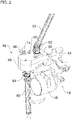
- the figure 2 shows the intermediate gear 16 and the steering gear 18 from the outside.
- the figure 3 shows the intermediate gear 16 without housing.
- the intermediate gear 16 has its own housing 46 .
- the housing 46 can be formed, for example, from two housing sections fastened to one another, for example housing halves.
- the housing 46 is a closed housing and sealed inwardly and outwardly. This means that no dirt can get into the housing 46 and no lubricant, for example lubricating grease, can escape from the housing 46 .
- the housing 46 is attached directly to a housing 48 of the steering gear 18 .
- housing 46 is secured by three screws 50 (only two screws in figure 2 visible) attached to the housing 48. Fastening takes place in a defined alignment, so that easy assembly and safe operation are guaranteed. Because the housings 46 and 48 are fastened to one another, there is no relative movement between the intermediate gear 16 and the steering gear 18.
- the steering joint shaft of the steering train 22 is articulated and drivingly connected to a stub shaft of a first drive shaft 52 of the intermediate gear 16 .
- the steering joint shaft 40 is articulated and drivingly connected to a stub shaft of a second drive shaft 54 of the intermediate gear 16 .
- the steering joint shaft of the steering train 22 and the steering joint shaft 40 are drivingly connected to respective input shafts 52 and 54 on opposite sides of the intermediate gearbox 16 .
- the shaft axes of the drive shafts 52 and 54 are essentially parallel to one another.
- the drive shafts 52 and 54 are rotatably mounted in the housing 46 of the intermediate gear 16 .
- the first drive shaft 52 is designed as a through shaft which is drivingly connected to the steering gear 18 via an output element 56 .
- the intermediate gear 16 is designed as a single-stage spur gear.
- a driven gear 58 is arranged on the first drive shaft 52 in a rotationally fixed manner.
- a driving gear wheel 60 is arranged on the second drive shaft 54 in a rotationally fixed manner.
- the gear ratio between the driving gear 60 and the driven gear 58 is 1.
- the intermediate gear 16 has a coupling mechanism 62 .
- the coupling mechanism 62 enables a coupling and decoupling of the second drive shaft 54 and the first drive shaft 52.
- the motor vehicle In the decoupled position of the coupling mechanism 62, the motor vehicle is by means of the main steering device 12 (see figure 1 ) steerable.
- the motor vehicle In the coupled position of the coupling mechanism 62, the motor vehicle is by means of the main steering device 12 and the additional steering device 14 (see figure 1 ) steerable.
- the coupling mechanism 62 has a sliding sleeve 64 and a shift fork 66 .
- the sliding sleeve 64 is arranged on a splined profile 68 of the second drive shaft 54 in a rotationally fixed and axially displaceable manner.
- the driving gear wheel 60 is connected to the sliding sleeve 64 in a torque-proof manner.
- the driving gear 60 and the sliding sleeve 64 can be screwed together.
- the shift fork 66 which engages in a peripheral groove of the sliding sleeve 64, the sliding sleeve 64 can be moved on the splined profile 68 together with the driving gear 60.
- the driving gear 60 can be selectively shifted into engagement with the driven gear 58 and out of engagement with the driven gear 58 .
- the driving gear 60 and the driven gear 58 mesh with each other.
- the coupling mechanism can also be constructed differently.
- the coupling mechanism may include a clutch, such as a dog clutch, that may provide a driving connection between the input gear 60 and the second input shaft 54 .
- a clutch such as a dog clutch
- the driving gear wheel 60 does not have to be shifted, but instead is constantly engaged with the driven gear wheel 58 .
- An actuating device 70 is provided for actuating the coupling mechanism 62 .
- the actuating device 70 has an actuating rod 72 , a handle 74 and an intermediate piece 76 .
- the actuating rod 72 can be moved manually by means of the handle 74 .
- the handle 74 can be easily reached from a driver's seat of the motor vehicle, for example, in order to move the actuating rod 72 .
- the actuating rod 72 is connected to the shift fork 66 via the intermediate piece 76 , so that a displacement of the actuating rod 72 results in a displacement of the shift fork 66 and thus a displacement of the sliding sleeve 72 and the driving gear wheel 60 .
- a driver of the motor vehicle can pull the actuating rod 72 upwards using the handle 74 in order to move the coupling mechanism 62 into the coupled position.
- the actuating device 70 and thus the coupling mechanism 62 are guided longitudinally on a guide device 78 .
- the guide device 78 has a guide rod 80 and a through hole in the intermediate piece 76 .
- the guide rod 80 is fixed in the housing 46 of the intermediate gear 16 .
- the actuating device 70 can be displaced longitudinally along the guide rod 80 by means of the through-hole of the intermediate piece 76 .
- the intermediate gear 16 also has a locking device 82 .
- the locking device 82 enables the coupling mechanism 62 to be locked in the coupled position and in the uncoupled position.
- a locking pin (locking bolt) 84 of the locking device 82 can be selectively inserted into one of two spaced through holes in the operating rod 72 to lock the operating rod 72 .
- the actuating device 70 and thus the coupling mechanism 62 cannot be displaced.
- the locking pin 84 can be gripped by means of a handle 86 that can be easily reached from the driver's seat of the motor vehicle. The handle 86 is attached to the locking pin 84 .
- handles 74 and 86 are located outside of housing 46 and are accessible.
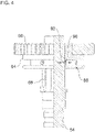
- a locking device 88 is shown.
- the latching device 88 enables the coupling mechanism 62 to be held in the engaged position, so that when the locking device 82 is released, the coupling mechanism 62 does not shift into the disengaged position without a specific actuation. Instead, in order to overcome the latching effect of the latching device 88 , a specific force must be applied by means of the actuating device 70 in order to displace the coupling mechanism 62 . It is also possible, for example, for an alternative or additional latching device to be provided in order to hold the coupling mechanism 62 in the uncoupled position.
- the latching device 88 has at least one spring-loaded latching body 90 which is slidably mounted in the sliding sleeve 64 .
- the locking body 90 is displaceable in a direction perpendicular to the shaft axis of the second drive shaft 54 .
- the coupling mechanism 62 When the coupling mechanism 62 is in the engaged position, the locking body 90 engages in a V-shaped circumferential groove 92 of the spline profile 68 .
- the sliding sleeve 64 is thus secured axially on the spline profile 68 .
- the latching body 90 can, for example, be designed as a ball or at least have a ball head.
- the sliding sleeve 64 can be shifted into the uncoupled position of the coupling mechanism 62 when the locking device 82 (see figure 3 ) is solved. It is also possible, for example, for the locking body to be displaceable in the second drive shaft 54 under spring pretension and for the circumferential groove to be arranged on an inner circumferential surface of the sliding sleeve 64 .
- the invention is not limited to the preferred embodiments described above. Rather, a large number of variants and modifications are possible, which also make use of the idea of the invention and therefore fall within the scope of protection.
- the invention also claims protection for the subject matter and the features of the subclaims independently of the claims referred to.
- the features of independent claim 1 are disclosed independently of each other.
- the features of the subclaims are also disclosed independently of all the features of independent claim 1 and, for example, independently of the features relating to the presence and/or configuration of the first drive shaft, the second drive shaft and/or the coupling mechanism of independent claim 1.
Landscapes
- Engineering & Computer Science (AREA)
- Chemical & Material Sciences (AREA)
- Mechanical Engineering (AREA)
- Theoretical Computer Science (AREA)
- Transportation (AREA)
- Combustion & Propulsion (AREA)
- Business, Economics & Management (AREA)
- General Physics & Mathematics (AREA)
- Educational Technology (AREA)
- Educational Administration (AREA)
- Physics & Mathematics (AREA)
- Aviation & Aerospace Engineering (AREA)
- Power Steering Mechanism (AREA)
Claims (14)
- Dispositif (10) de direction d'un véhicule automobile, notamment d'un véhicule utilitaire, comprenant :un appareil de direction principal côté conducteur (12) ;un appareil de direction supplémentaire côté passager (14) ;un engrenage intermédiaire (16) présentant :- un premier arbre d'entraînement (52), qui est relié en entraînement à un brin de direction (22) de l'appareil de direction principal (12) ;- un deuxième arbre d'entraînement (54), qui est relié en entraînement à un brin de direction (26) de l'appareil de direction supplémentaire (14) ;- un mécanisme d'accouplement (62), qui est configuré pour accoupler et désaccoupler sélectivement le premier arbre d'entraînement (52) et le deuxième arbre d'entraînement (54) ; et- un boîtier (46), dans lequel le premier arbre d'entraînement (52) et le deuxième arbre d'entraînement (54) sont reçus de manière rotative ; etun appareil de guidage (78), au moyen duquel le mécanisme d'accouplement (62) est guidé.
- Dispositif (10) selon la revendication 1, dans lequel :le boîtier (46) est un boîtier étanchéifié et/ou fermé ; et/oule mécanisme d'accouplement (62) est reçu dans le boîtier (46) .
- Dispositif (10) selon la revendication 1 ou la revendication 2, dans lequel :l'engrenage intermédiaire (16) est configuré sous la forme d'un engrenage droit, notamment à un étage ; et/ou l'engrenage intermédiaire (16) présente un rapport de transmission de 1 ; et/oul'appareil de direction supplémentaire (14) et l'appareil de direction principal (12) peuvent être reliés en entraînement à l'engrenage intermédiaire (16) sur des côtés opposés de l'engrenage intermédiaire (16).
- Dispositif (10) selon l'une quelconque des revendications précédentes, dans lequel :le premier arbre d'entraînement (52) est relié de manière immobile en rotation à une roue dentée menée (58) ;le deuxième arbre d'entraînement (54) est relié de manière immobile en rotation à une roue dentée menante (60) ; etle mécanisme d'accouplement (62) est configuré pour accoupler et désaccoupler sélectivement la roue dentée menante (60) et la roue dentée menée (58).
- Dispositif (10) selon l'une quelconque des revendications précédentes, dans lequel :
le mécanisme d'accouplement (62) présente un manchon coulissant (64) ou un embrayage, notamment un embrayage à crabots. - Dispositif (10) selon la revendication 5, dans lequel :
la roue dentée menante (60) peut coulisser avec le manchon coulissant (64) pour venir en prise avec la roue dentée menée (58) et s'en dégager. - Dispositif (10) selon la revendication 5 ou la revendication 6, dans lequel :le manchon coulissant (64) peut coulisser sur un profil cannelé (68) du deuxième arbre d'entraînement (54) ; et/oule manchon coulissant (64) peut coulisser au moyen d'une fourchette de commutation (66).
- Dispositif (10) selon l'une quelconque des revendications précédentes, dans lequel :
l'appareil de guidage (78) présente une tige de guidage (80) et/ou le mécanisme d'accouplement (62) est guidé longitudinalement au moyen de l'appareil de guidage (78). - Dispositif (10) selon l'une quelconque des revendications précédentes, présentant en outre :
un appareil de blocage (82), présentant notamment une goupille de sécurité (84), au moyen duquel le mécanisme d'accouplement (72) peut être bloqué dans une position accouplée et/ou une position désaccouplée. - Dispositif (10) selon l'une quelconque des revendications précédentes, présentant en outre :
un appareil d'encliquetage (88), présentant notamment un corps d'encliquetage (90) précontraint par ressort, pouvant être encliqueté dans une rainure périphérique (92), au moyen duquel le mécanisme d'accouplement (62) peut être encliqueté dans une position accouplée et/ou une position désaccouplée. - Dispositif (10) selon l'une quelconque des revendications précédentes, présentant en outre :
un appareil d'actionnement (70), présentant notamment une tige d'actionnement (72), au moyen duquel le mécanisme d'accouplement (62) peut être actionné manuellement. - Dispositif (10) selon la revendication 11, présentant en outre :
un mécanisme de direction (18), notamment pour convertir un mouvement de rotation entrant en un mouvement de coulissement sortant, l'engrenage intermédiaire (16) étant relié en entraînement au mécanisme de direction (18) . - Dispositif (10) selon la revendication 12, dans lequel :
le boîtier (46) de l'engrenage intermédiaire (16) et un boîtier (48) du mécanisme de direction (18) sont fixés l'un à l'autre de manière amovible et/ou selon une orientation définie l'un par rapport à l'autre. - Véhicule automobile, notamment véhicule utilitaire, comprenant un dispositif (10) selon l'une quelconque des revendications précédentes.
Applications Claiming Priority (1)
| Application Number | Priority Date | Filing Date | Title |
|---|---|---|---|
| ATA504/2017A AT520759B1 (de) | 2017-12-29 | 2017-12-29 | Vorrichtung zum Lenken eines Kraftfahrzeugs und Zwischengetriebe hierfür |
Publications (2)
| Publication Number | Publication Date |
|---|---|
| EP3508397A1 EP3508397A1 (fr) | 2019-07-10 |
| EP3508397B1 true EP3508397B1 (fr) | 2022-06-22 |
Family
ID=64572190
Family Applications (1)
| Application Number | Title | Priority Date | Filing Date |
|---|---|---|---|
| EP18209784.0A Active EP3508397B1 (fr) | 2017-12-29 | 2018-12-03 | Dispositif de direction d'un véhicule automobile et transmission intermédiaire correspondante |
Country Status (2)
| Country | Link |
|---|---|
| EP (1) | EP3508397B1 (fr) |
| AT (1) | AT520759B1 (fr) |
Cited By (1)
| Publication number | Priority date | Publication date | Assignee | Title |
|---|---|---|---|---|
| US20240278823A1 (en) * | 2023-02-16 | 2024-08-22 | Fontaine Modification Company | Assembly for equipping motor vehicle with dual-steer capabilities |
Families Citing this family (2)
| Publication number | Priority date | Publication date | Assignee | Title |
|---|---|---|---|---|
| CN114560008B (zh) * | 2020-11-27 | 2024-03-19 | 比亚迪股份有限公司 | 转向系统和车辆 |
| DE102024102727A1 (de) * | 2024-01-31 | 2025-07-31 | Bayerische Motoren Werke Aktiengesellschaft | Simulationssteuerung in einem Kraftfahrzeug |
Family Cites Families (6)
| Publication number | Priority date | Publication date | Assignee | Title |
|---|---|---|---|---|
| GB204340A (en) * | 1922-09-23 | 1924-02-28 | Joan Dimitriu | Improvements in or relating to steering and controlling devices for power-driven vehicles for instruction purposes |
| DE1530548A1 (de) * | 1965-03-10 | 1969-06-19 | Daimler Benz Ag | Mehrradlenkung fuer Kraftfahrzeuge |
| JPS57139473U (fr) * | 1981-02-27 | 1982-08-31 | ||
| CN201984662U (zh) * | 2011-03-14 | 2011-09-21 | 安徽江淮客车有限公司 | 一种教练车转向传动装置 |
| CN106218703B (zh) * | 2016-09-12 | 2018-11-06 | 北京汽车股份有限公司 | 教练车、教练车转向系统及其控制方法 |
| AT518994B1 (de) * | 2016-10-25 | 2018-03-15 | MAN TRUCK & BUS OESTERREICH GesmbH | Lenksystem für ein Kraftfahrzeug, vorzugsweise Fahrschul-Kraftfahrzeug |
-
2017
- 2017-12-29 AT ATA504/2017A patent/AT520759B1/de active
-
2018
- 2018-12-03 EP EP18209784.0A patent/EP3508397B1/fr active Active
Cited By (2)
| Publication number | Priority date | Publication date | Assignee | Title |
|---|---|---|---|---|
| US20240278823A1 (en) * | 2023-02-16 | 2024-08-22 | Fontaine Modification Company | Assembly for equipping motor vehicle with dual-steer capabilities |
| US12434758B2 (en) * | 2023-02-16 | 2025-10-07 | Fontaine Modification Company | Assembly for equipping motor vehicle with dual-steer capabilities |
Also Published As
| Publication number | Publication date |
|---|---|
| AT520759B1 (de) | 2019-10-15 |
| EP3508397A1 (fr) | 2019-07-10 |
| AT520759A1 (de) | 2019-07-15 |
Similar Documents
| Publication | Publication Date | Title |
|---|---|---|
| DE10162337B4 (de) | Längs eingebauter Antriebsstrang | |
| DE3334905A1 (de) | Kraftwagen mit vierradantrieb | |
| EP2616264B1 (fr) | Engrenage distributeur | |
| EP3508397B1 (fr) | Dispositif de direction d'un véhicule automobile et transmission intermédiaire correspondante | |
| EP3707024B1 (fr) | Groupe motopropulseur modulaire et véhicule équipé d'un tel groupe motopropulseur | |
| DE102016204560A1 (de) | Lenksystem für ein lenkbares Fahrzeug | |
| DE3873440T2 (de) | Fahrzeug fuer gartenarbeiten sowie landwirtschaftliche arbeiten. | |
| DE1430831A1 (de) | Mehrrad-,insbesondere Vierradantriebseinheit | |
| DE102019000035A1 (de) | Lenkeinrichtung für ein autonom betreibbares Kraftfahrzeug sowie Verfahren zum Betreiben einer Lenkeinrichtung | |
| EP3315382B1 (fr) | Système de guidage pour un véhicule automobile, de préférence un véhicule automobile des écoles de conduite | |
| DE2605674C2 (de) | Getriebeanordnung für Dreiachs- Kraftfahrzeuge mit Allradantrieb | |
| DE102013222086A1 (de) | Antriebsstrang für ein Schienenfahrzeug | |
| DE112008003397T5 (de) | Lenkvorrichtung | |
| DE1555953C3 (de) | Antriebseinrichtung für wahlweise In Zwei-Rad- oder Vier-Rad-Antrieb zu schaltende Kraftfahrzeuge, insbesondere Mähdrescher | |
| DE69814989T2 (de) | Geländefahrzeug mit lenkbarer Vorderachse und Frontzapfwellenkupplung | |
| DE69009565T2 (de) | Differentialgetriebe. | |
| DE102008009060B4 (de) | Elektrische Servolenkung mit angetriebener Lenkwelle | |
| DE3920934A1 (de) | Anhaengereigene antriebseinrichtung | |
| DE102022001304A1 (de) | Differentialgetriebe und Antriebsstrang mit einem solchen Differentialgetriebe | |
| EP3348454B1 (fr) | Transmission pour un véhicule sur roues et/ou à chenilles | |
| EP2671738A2 (fr) | Système d'actionnement pour un attelage de véhicule automobile | |
| DE102015220776A1 (de) | Radaufhängung für ein lenkbares Fahrzeugrad eines Kraftfahrzeuges | |
| DE102022119195B4 (de) | Getriebe, Kraftfahrzeug und Verfahren zum Betreiben eines entsprechenden Getriebes | |
| DE102008031204B4 (de) | Lenkeinrichtung für ein Radfahrzeug mit Achsschenkellenkung | |
| DE102018219600B4 (de) | Dämpfungseinrichtung für einen Antriebsstrang eines Kraftfahrzeugs, Antriebsstrang für ein Kraftfahrzeug, sowie Kraftfahrzeug |
Legal Events
| Date | Code | Title | Description |
|---|---|---|---|
| PUAI | Public reference made under article 153(3) epc to a published international application that has entered the european phase |
Free format text: ORIGINAL CODE: 0009012 |
|
| STAA | Information on the status of an ep patent application or granted ep patent |
Free format text: STATUS: THE APPLICATION HAS BEEN PUBLISHED |
|
| AK | Designated contracting states |
Kind code of ref document: A1 Designated state(s): AL AT BE BG CH CY CZ DE DK EE ES FI FR GB GR HR HU IE IS IT LI LT LU LV MC MK MT NL NO PL PT RO RS SE SI SK SM TR |
|
| AX | Request for extension of the european patent |
Extension state: BA ME |
|
| STAA | Information on the status of an ep patent application or granted ep patent |
Free format text: STATUS: REQUEST FOR EXAMINATION WAS MADE |
|
| 17P | Request for examination filed |
Effective date: 20200109 |
|
| RBV | Designated contracting states (corrected) |
Designated state(s): AL AT BE BG CH CY CZ DE DK EE ES FI FR GB GR HR HU IE IS IT LI LT LU LV MC MK MT NL NO PL PT RO RS SE SI SK SM TR |
|
| STAA | Information on the status of an ep patent application or granted ep patent |
Free format text: STATUS: EXAMINATION IS IN PROGRESS |
|
| 17Q | First examination report despatched |
Effective date: 20201218 |
|
| RAP1 | Party data changed (applicant data changed or rights of an application transferred) |
Owner name: MAN TRUCK & BUS SE |
|
| GRAP | Despatch of communication of intention to grant a patent |
Free format text: ORIGINAL CODE: EPIDOSNIGR1 |
|
| STAA | Information on the status of an ep patent application or granted ep patent |
Free format text: STATUS: GRANT OF PATENT IS INTENDED |
|
| INTG | Intention to grant announced |
Effective date: 20220117 |
|
| GRAS | Grant fee paid |
Free format text: ORIGINAL CODE: EPIDOSNIGR3 |
|
| GRAA | (expected) grant |
Free format text: ORIGINAL CODE: 0009210 |
|
| STAA | Information on the status of an ep patent application or granted ep patent |
Free format text: STATUS: THE PATENT HAS BEEN GRANTED |
|
| AK | Designated contracting states |
Kind code of ref document: B1 Designated state(s): AL AT BE BG CH CY CZ DE DK EE ES FI FR GB GR HR HU IE IS IT LI LT LU LV MC MK MT NL NO PL PT RO RS SE SI SK SM TR |
|
| REG | Reference to a national code |
Ref country code: GB Ref legal event code: FG4D Free format text: NOT ENGLISH |
|
| REG | Reference to a national code |
Ref country code: CH Ref legal event code: EP |
|
| REG | Reference to a national code |
Ref country code: DE Ref legal event code: R096 Ref document number: 502018009970 Country of ref document: DE |
|
| REG | Reference to a national code |
Ref country code: AT Ref legal event code: REF Ref document number: 1499613 Country of ref document: AT Kind code of ref document: T Effective date: 20220715 |
|
| REG | Reference to a national code |
Ref country code: IE Ref legal event code: FG4D Free format text: LANGUAGE OF EP DOCUMENT: GERMAN |
|
| REG | Reference to a national code |
Ref country code: NL Ref legal event code: FP |
|
| REG | Reference to a national code |
Ref country code: SE Ref legal event code: TRGR |
|
| REG | Reference to a national code |
Ref country code: LT Ref legal event code: MG9D |
|
| PG25 | Lapsed in a contracting state [announced via postgrant information from national office to epo] |
Ref country code: NO Free format text: LAPSE BECAUSE OF FAILURE TO SUBMIT A TRANSLATION OF THE DESCRIPTION OR TO PAY THE FEE WITHIN THE PRESCRIBED TIME-LIMIT Effective date: 20220922 Ref country code: LT Free format text: LAPSE BECAUSE OF FAILURE TO SUBMIT A TRANSLATION OF THE DESCRIPTION OR TO PAY THE FEE WITHIN THE PRESCRIBED TIME-LIMIT Effective date: 20220622 Ref country code: HR Free format text: LAPSE BECAUSE OF FAILURE TO SUBMIT A TRANSLATION OF THE DESCRIPTION OR TO PAY THE FEE WITHIN THE PRESCRIBED TIME-LIMIT Effective date: 20220622 Ref country code: GR Free format text: LAPSE BECAUSE OF FAILURE TO SUBMIT A TRANSLATION OF THE DESCRIPTION OR TO PAY THE FEE WITHIN THE PRESCRIBED TIME-LIMIT Effective date: 20220923 Ref country code: FI Free format text: LAPSE BECAUSE OF FAILURE TO SUBMIT A TRANSLATION OF THE DESCRIPTION OR TO PAY THE FEE WITHIN THE PRESCRIBED TIME-LIMIT Effective date: 20220622 Ref country code: BG Free format text: LAPSE BECAUSE OF FAILURE TO SUBMIT A TRANSLATION OF THE DESCRIPTION OR TO PAY THE FEE WITHIN THE PRESCRIBED TIME-LIMIT Effective date: 20220922 |
|
| PG25 | Lapsed in a contracting state [announced via postgrant information from national office to epo] |
Ref country code: RS Free format text: LAPSE BECAUSE OF FAILURE TO SUBMIT A TRANSLATION OF THE DESCRIPTION OR TO PAY THE FEE WITHIN THE PRESCRIBED TIME-LIMIT Effective date: 20220622 Ref country code: LV Free format text: LAPSE BECAUSE OF FAILURE TO SUBMIT A TRANSLATION OF THE DESCRIPTION OR TO PAY THE FEE WITHIN THE PRESCRIBED TIME-LIMIT Effective date: 20220622 |
|
| PG25 | Lapsed in a contracting state [announced via postgrant information from national office to epo] |
Ref country code: SM Free format text: LAPSE BECAUSE OF FAILURE TO SUBMIT A TRANSLATION OF THE DESCRIPTION OR TO PAY THE FEE WITHIN THE PRESCRIBED TIME-LIMIT Effective date: 20220622 Ref country code: SK Free format text: LAPSE BECAUSE OF FAILURE TO SUBMIT A TRANSLATION OF THE DESCRIPTION OR TO PAY THE FEE WITHIN THE PRESCRIBED TIME-LIMIT Effective date: 20220622 Ref country code: RO Free format text: LAPSE BECAUSE OF FAILURE TO SUBMIT A TRANSLATION OF THE DESCRIPTION OR TO PAY THE FEE WITHIN THE PRESCRIBED TIME-LIMIT Effective date: 20220622 Ref country code: PT Free format text: LAPSE BECAUSE OF FAILURE TO SUBMIT A TRANSLATION OF THE DESCRIPTION OR TO PAY THE FEE WITHIN THE PRESCRIBED TIME-LIMIT Effective date: 20221024 Ref country code: ES Free format text: LAPSE BECAUSE OF FAILURE TO SUBMIT A TRANSLATION OF THE DESCRIPTION OR TO PAY THE FEE WITHIN THE PRESCRIBED TIME-LIMIT Effective date: 20220622 Ref country code: EE Free format text: LAPSE BECAUSE OF FAILURE TO SUBMIT A TRANSLATION OF THE DESCRIPTION OR TO PAY THE FEE WITHIN THE PRESCRIBED TIME-LIMIT Effective date: 20220622 Ref country code: CZ Free format text: LAPSE BECAUSE OF FAILURE TO SUBMIT A TRANSLATION OF THE DESCRIPTION OR TO PAY THE FEE WITHIN THE PRESCRIBED TIME-LIMIT Effective date: 20220622 |
|
| PG25 | Lapsed in a contracting state [announced via postgrant information from national office to epo] |
Ref country code: PL Free format text: LAPSE BECAUSE OF FAILURE TO SUBMIT A TRANSLATION OF THE DESCRIPTION OR TO PAY THE FEE WITHIN THE PRESCRIBED TIME-LIMIT Effective date: 20220622 Ref country code: IS Free format text: LAPSE BECAUSE OF FAILURE TO SUBMIT A TRANSLATION OF THE DESCRIPTION OR TO PAY THE FEE WITHIN THE PRESCRIBED TIME-LIMIT Effective date: 20221022 |
|
| REG | Reference to a national code |
Ref country code: DE Ref legal event code: R097 Ref document number: 502018009970 Country of ref document: DE |
|
| PG25 | Lapsed in a contracting state [announced via postgrant information from national office to epo] |
Ref country code: AL Free format text: LAPSE BECAUSE OF FAILURE TO SUBMIT A TRANSLATION OF THE DESCRIPTION OR TO PAY THE FEE WITHIN THE PRESCRIBED TIME-LIMIT Effective date: 20220622 |
|
| PG25 | Lapsed in a contracting state [announced via postgrant information from national office to epo] |
Ref country code: DK Free format text: LAPSE BECAUSE OF FAILURE TO SUBMIT A TRANSLATION OF THE DESCRIPTION OR TO PAY THE FEE WITHIN THE PRESCRIBED TIME-LIMIT Effective date: 20220622 |
|
| PLBE | No opposition filed within time limit |
Free format text: ORIGINAL CODE: 0009261 |
|
| STAA | Information on the status of an ep patent application or granted ep patent |
Free format text: STATUS: NO OPPOSITION FILED WITHIN TIME LIMIT |
|
| 26N | No opposition filed |
Effective date: 20230323 |
|
| REG | Reference to a national code |
Ref country code: CH Ref legal event code: PL |
|
| GBPC | Gb: european patent ceased through non-payment of renewal fee |
Effective date: 20221203 |
|
| REG | Reference to a national code |
Ref country code: BE Ref legal event code: MM Effective date: 20221231 |
|
| PG25 | Lapsed in a contracting state [announced via postgrant information from national office to epo] |
Ref country code: SI Free format text: LAPSE BECAUSE OF FAILURE TO SUBMIT A TRANSLATION OF THE DESCRIPTION OR TO PAY THE FEE WITHIN THE PRESCRIBED TIME-LIMIT Effective date: 20220622 Ref country code: LU Free format text: LAPSE BECAUSE OF NON-PAYMENT OF DUE FEES Effective date: 20221203 |
|
| PG25 | Lapsed in a contracting state [announced via postgrant information from national office to epo] |
Ref country code: LI Free format text: LAPSE BECAUSE OF NON-PAYMENT OF DUE FEES Effective date: 20221231 Ref country code: IE Free format text: LAPSE BECAUSE OF NON-PAYMENT OF DUE FEES Effective date: 20221203 Ref country code: GB Free format text: LAPSE BECAUSE OF NON-PAYMENT OF DUE FEES Effective date: 20221203 Ref country code: CH Free format text: LAPSE BECAUSE OF NON-PAYMENT OF DUE FEES Effective date: 20221231 |
|
| PG25 | Lapsed in a contracting state [announced via postgrant information from national office to epo] |
Ref country code: BE Free format text: LAPSE BECAUSE OF NON-PAYMENT OF DUE FEES Effective date: 20221231 |
|
| PG25 | Lapsed in a contracting state [announced via postgrant information from national office to epo] |
Ref country code: HU Free format text: LAPSE BECAUSE OF FAILURE TO SUBMIT A TRANSLATION OF THE DESCRIPTION OR TO PAY THE FEE WITHIN THE PRESCRIBED TIME-LIMIT; INVALID AB INITIO Effective date: 20181203 |
|
| PG25 | Lapsed in a contracting state [announced via postgrant information from national office to epo] |
Ref country code: CY Free format text: LAPSE BECAUSE OF FAILURE TO SUBMIT A TRANSLATION OF THE DESCRIPTION OR TO PAY THE FEE WITHIN THE PRESCRIBED TIME-LIMIT Effective date: 20220622 |
|
| PG25 | Lapsed in a contracting state [announced via postgrant information from national office to epo] |
Ref country code: MK Free format text: LAPSE BECAUSE OF FAILURE TO SUBMIT A TRANSLATION OF THE DESCRIPTION OR TO PAY THE FEE WITHIN THE PRESCRIBED TIME-LIMIT Effective date: 20220622 |
|
| PG25 | Lapsed in a contracting state [announced via postgrant information from national office to epo] |
Ref country code: MC Free format text: LAPSE BECAUSE OF FAILURE TO SUBMIT A TRANSLATION OF THE DESCRIPTION OR TO PAY THE FEE WITHIN THE PRESCRIBED TIME-LIMIT Effective date: 20220622 |
|
| PG25 | Lapsed in a contracting state [announced via postgrant information from national office to epo] |
Ref country code: MC Free format text: LAPSE BECAUSE OF FAILURE TO SUBMIT A TRANSLATION OF THE DESCRIPTION OR TO PAY THE FEE WITHIN THE PRESCRIBED TIME-LIMIT Effective date: 20220622 |
|
| PG25 | Lapsed in a contracting state [announced via postgrant information from national office to epo] |
Ref country code: MT Free format text: LAPSE BECAUSE OF FAILURE TO SUBMIT A TRANSLATION OF THE DESCRIPTION OR TO PAY THE FEE WITHIN THE PRESCRIBED TIME-LIMIT Effective date: 20220622 |
|
| PG25 | Lapsed in a contracting state [announced via postgrant information from national office to epo] |
Ref country code: BG Free format text: LAPSE BECAUSE OF FAILURE TO SUBMIT A TRANSLATION OF THE DESCRIPTION OR TO PAY THE FEE WITHIN THE PRESCRIBED TIME-LIMIT Effective date: 20220622 |
|
| PG25 | Lapsed in a contracting state [announced via postgrant information from national office to epo] |
Ref country code: BG Free format text: LAPSE BECAUSE OF FAILURE TO SUBMIT A TRANSLATION OF THE DESCRIPTION OR TO PAY THE FEE WITHIN THE PRESCRIBED TIME-LIMIT Effective date: 20220622 |
|
| REG | Reference to a national code |
Ref country code: AT Ref legal event code: MM01 Ref document number: 1499613 Country of ref document: AT Kind code of ref document: T Effective date: 20231203 |
|
| PG25 | Lapsed in a contracting state [announced via postgrant information from national office to epo] |
Ref country code: AT Free format text: LAPSE BECAUSE OF NON-PAYMENT OF DUE FEES Effective date: 20231203 |
|
| PG25 | Lapsed in a contracting state [announced via postgrant information from national office to epo] |
Ref country code: TR Free format text: LAPSE BECAUSE OF FAILURE TO SUBMIT A TRANSLATION OF THE DESCRIPTION OR TO PAY THE FEE WITHIN THE PRESCRIBED TIME-LIMIT Effective date: 20220622 |
|
| PGFP | Annual fee paid to national office [announced via postgrant information from national office to epo] |
Ref country code: IT Payment date: 20251218 Year of fee payment: 8 |
|
| PGFP | Annual fee paid to national office [announced via postgrant information from national office to epo] |
Ref country code: FR Payment date: 20251230 Year of fee payment: 8 Ref country code: NL Payment date: 20251222 Year of fee payment: 8 |
|
| PGFP | Annual fee paid to national office [announced via postgrant information from national office to epo] |
Ref country code: SE Payment date: 20251222 Year of fee payment: 8 |
|
| PGFP | Annual fee paid to national office [announced via postgrant information from national office to epo] |
Ref country code: DE Payment date: 20251229 Year of fee payment: 8 |
|
| PGFP | Annual fee paid to national office [announced via postgrant information from national office to epo] |
Ref country code: AT Payment date: 20260410 Year of fee payment: 5 |