EP3507518B1 - Mehrfach-kupplung für ein kraftfahrzeug, insbesondere für einen hybridantrieb eines kraftfahrzeugs - Google Patents
Mehrfach-kupplung für ein kraftfahrzeug, insbesondere für einen hybridantrieb eines kraftfahrzeugs Download PDFInfo
- Publication number
- EP3507518B1 EP3507518B1 EP17735504.7A EP17735504A EP3507518B1 EP 3507518 B1 EP3507518 B1 EP 3507518B1 EP 17735504 A EP17735504 A EP 17735504A EP 3507518 B1 EP3507518 B1 EP 3507518B1
- Authority
- EP
- European Patent Office
- Prior art keywords
- clutch
- separating
- clutches
- carrier
- essentially
- Prior art date
- Legal status (The legal status is an assumption and is not a legal conclusion. Google has not performed a legal analysis and makes no representation as to the accuracy of the status listed.)
- Active
Links
Images

Classifications
-
- F—MECHANICAL ENGINEERING; LIGHTING; HEATING; WEAPONS; BLASTING
- F16—ENGINEERING ELEMENTS AND UNITS; GENERAL MEASURES FOR PRODUCING AND MAINTAINING EFFECTIVE FUNCTIONING OF MACHINES OR INSTALLATIONS; THERMAL INSULATION IN GENERAL
- F16D—COUPLINGS FOR TRANSMITTING ROTATION; CLUTCHES; BRAKES
- F16D25/00—Fluid-actuated clutches
- F16D25/12—Details not specific to one of the before-mentioned types
- F16D25/123—Details not specific to one of the before-mentioned types in view of cooling and lubrication
-
- B—PERFORMING OPERATIONS; TRANSPORTING
- B60—VEHICLES IN GENERAL
- B60K—ARRANGEMENT OR MOUNTING OF PROPULSION UNITS OR OF TRANSMISSIONS IN VEHICLES; ARRANGEMENT OR MOUNTING OF PLURAL DIVERSE PRIME-MOVERS IN VEHICLES; AUXILIARY DRIVES FOR VEHICLES; INSTRUMENTATION OR DASHBOARDS FOR VEHICLES; ARRANGEMENTS IN CONNECTION WITH COOLING, AIR INTAKE, GAS EXHAUST OR FUEL SUPPLY OF PROPULSION UNITS IN VEHICLES
- B60K6/00—Arrangement or mounting of plural diverse prime-movers for mutual or common propulsion, e.g. hybrid propulsion systems comprising electric motors and internal combustion engines
- B60K6/20—Arrangement or mounting of plural diverse prime-movers for mutual or common propulsion, e.g. hybrid propulsion systems comprising electric motors and internal combustion engines the prime-movers consisting of electric motors and internal combustion engines, e.g. HEVs
- B60K6/22—Arrangement or mounting of plural diverse prime-movers for mutual or common propulsion, e.g. hybrid propulsion systems comprising electric motors and internal combustion engines the prime-movers consisting of electric motors and internal combustion engines, e.g. HEVs characterised by apparatus, components or means specially adapted for HEVs
- B60K6/38—Arrangement or mounting of plural diverse prime-movers for mutual or common propulsion, e.g. hybrid propulsion systems comprising electric motors and internal combustion engines the prime-movers consisting of electric motors and internal combustion engines, e.g. HEVs characterised by apparatus, components or means specially adapted for HEVs characterised by the driveline clutches
- B60K6/387—Actuated clutches, i.e. clutches engaged or disengaged by electric, hydraulic or mechanical actuating means
-
- B—PERFORMING OPERATIONS; TRANSPORTING
- B60—VEHICLES IN GENERAL
- B60W—CONJOINT CONTROL OF VEHICLE SUB-UNITS OF DIFFERENT TYPE OR DIFFERENT FUNCTION; CONTROL SYSTEMS SPECIALLY ADAPTED FOR HYBRID VEHICLES; ROAD VEHICLE DRIVE CONTROL SYSTEMS FOR PURPOSES NOT RELATED TO THE CONTROL OF A PARTICULAR SUB-UNIT
- B60W10/00—Conjoint control of vehicle sub-units of different type or different function
- B60W10/02—Conjoint control of vehicle sub-units of different type or different function including control of driveline clutches
-
- F—MECHANICAL ENGINEERING; LIGHTING; HEATING; WEAPONS; BLASTING
- F16—ENGINEERING ELEMENTS AND UNITS; GENERAL MEASURES FOR PRODUCING AND MAINTAINING EFFECTIVE FUNCTIONING OF MACHINES OR INSTALLATIONS; THERMAL INSULATION IN GENERAL
- F16D—COUPLINGS FOR TRANSMITTING ROTATION; CLUTCHES; BRAKES
- F16D21/00—Systems comprising a plurality of actuated clutches
- F16D21/02—Systems comprising a plurality of actuated clutches for interconnecting three or more shafts or other transmission members in different ways
- F16D21/06—Systems comprising a plurality of actuated clutches for interconnecting three or more shafts or other transmission members in different ways at least two driving shafts or two driven shafts being concentric
-
- F—MECHANICAL ENGINEERING; LIGHTING; HEATING; WEAPONS; BLASTING
- F16—ENGINEERING ELEMENTS AND UNITS; GENERAL MEASURES FOR PRODUCING AND MAINTAINING EFFECTIVE FUNCTIONING OF MACHINES OR INSTALLATIONS; THERMAL INSULATION IN GENERAL
- F16D—COUPLINGS FOR TRANSMITTING ROTATION; CLUTCHES; BRAKES
- F16D25/00—Fluid-actuated clutches
- F16D25/10—Clutch systems with a plurality of fluid-actuated clutches
-
- F—MECHANICAL ENGINEERING; LIGHTING; HEATING; WEAPONS; BLASTING
- F16—ENGINEERING ELEMENTS AND UNITS; GENERAL MEASURES FOR PRODUCING AND MAINTAINING EFFECTIVE FUNCTIONING OF MACHINES OR INSTALLATIONS; THERMAL INSULATION IN GENERAL
- F16D—COUPLINGS FOR TRANSMITTING ROTATION; CLUTCHES; BRAKES
- F16D21/00—Systems comprising a plurality of actuated clutches
- F16D21/02—Systems comprising a plurality of actuated clutches for interconnecting three or more shafts or other transmission members in different ways
- F16D21/06—Systems comprising a plurality of actuated clutches for interconnecting three or more shafts or other transmission members in different ways at least two driving shafts or two driven shafts being concentric
- F16D2021/0661—Hydraulically actuated multiple lamellae clutches
Definitions
- the invention relates to a multiple clutch for a motor vehicle, in particular for a hybrid drive of a motor vehicle, according to the features of the preamble of patent claim 1.
- such multiple clutches have a first, a second and a third separating clutch, which are designed in particular as friction multi-plate clutches.
- the first separating clutch is provided for coupling or decoupling a — first — transmission input shaft with a drive, in particular with an internal combustion engine and / or with an electric machine.
- a second separating clutch is then provided, which is provided for coupling or decoupling the then provided second transmission input shaft with a drive, in particular with an internal combustion engine or with an electric machine.
- the first and second separating clutches are each essentially designed as a multi-disc clutch and have an inner and outer disc carrier or corresponding inner and outer discs.
- the third separating clutch is used to couple or decouple the outer plate carrier of the first and second separating clutch with a drive, in particular with an internal combustion engine and / or with an electric machine, or is the third separating clutch, which can also be referred to as the so-called "K0 clutch” , in particular provided for the selection of the drive acting on the first or second separating clutch, in particular for implementing the internal combustion engine drive.
- a multiple clutch system which has a first, second and third separating clutch, the first and the second separating clutch each having a separate inner and outer disk carrier. Furthermore, this multiple clutch system has a corresponding cooling oil system for cooling the three separating clutches.
- the cooling oil system is designed so that initially a common cooling oil supply then divides into a first and a second flow path in the further course, the first flow path supplying the first and the second separating clutch and the second flow path correspondingly supplying the third separating clutch with cooling oil.
- the multiple clutch system described here is preferably suitable for a double clutch transmission or is essentially designed in particular as a double clutch with a first and second separating clutch or an attached third separating clutch (K0 clutch).
- a multiple clutch for a motor vehicle designed in particular as a double clutch, namely here the first and second separating clutch, having an inner and outer disk carrier.
- the outer disk carrier of the first clutch is also designed as the inner disk carrier of the second separating clutch.
- a cooling oil system is also provided, wherein the first separating coupling on the one hand and the second separating coupling can be supplied with cooling oil on the other hand via two feed channels provided separately from one another.
- a multiple clutch known for a motor vehicle where a first, a second and a third separating clutch have an outer disk carrier and the outer disk carrier of the first, the second and the third separating clutch is designed as a common outer disk carrier. At least two of the separating clutches provided or present here are arranged radially spaced from one another or radially spaced from one another. The entire structure of this multiple coupling is complex and expensive.
- the multiple clutches or multiple clutch systems known in the prior art are not yet optimally designed.
- the construction and assembly effort for the known multiple clutches is increased; in particular, different plates, in particular differently designed and / or differently dimensioned friction plates, have to be produced for the first and second separating clutch and also for the third separating clutch, which also need to be produced in several assembly steps must be arranged or positioned accordingly.
- the cooling oil systems in the already known multiple clutches or multiple clutch systems are not yet optimal. Due to the complex spatial arrangements of the respective inner and outer disk carriers of the first, second and third separating clutches, some complex ones have to be Cooling oil channels are formed or implemented, which in turn increases the production costs accordingly.
- the invention is therefore based on the object of designing and developing the multiple coupling mentioned at the outset in such a way that the construction and assembly effort and, in particular, the associated costs are reduced, in particular the implementation of a cooling oil system is also simplified.
- the third separating clutch is designed as a multi-plate clutch and has an inner and an outer plate carrier, but now the outer plate carrier of the first, the second and the third separating clutch as a common outer plate carrier for receiving, mounting and / or guiding the outer plates of the first, second and third separating clutch is formed.
- the common outer disk carrier has a continuous toothing, namely in particular on the inner circumference, axial grooves extending essentially over the axial length of the outer disk carrier.
- the assembly effort for arranging the outer disks is considerably reduced or simplified, namely the corresponding outer disks of the first, second and third separating clutches can each be pushed sequentially into the axial grooves of the common outer disk carrier and positioned at the corresponding points as desired.
- first, second and third separating clutches with a common outer disk carrier, in particular the outer disks, in particular outer disks made of steel, of the first, second and third separating clutches can be designed essentially identically and / or have the same dimensions. The manufacturing effort and the manufacturing costs are significantly reduced.
- the first, second and third separating clutches each have a separate inner disk carrier, but the toothing of the respective inner disk carrier is essentially the same and / or has the same dimensions.
- the inner lamellae, in particular Facing disks of the first, second and third separating clutch are designed the same and / or have the same dimensions. This also significantly reduces the manufacturing effort and the associated costs.
- Spring elements are provided between the individual disks of the respective disconnect clutch, in particular between the outer disks of the first, second and / or third disconnect clutch, in particular to move the inner and outer disks of this respective disconnect clutch away from each other or to create a possible drag torque when the respective disconnect clutch is not under load to minimize. Due to the design and / or the arrangement of the outer disks in a common outer disk carrier, the spring elements of the first, second and / or third separating clutch can now also have essentially the same design and / or the same dimensions. This in turn reduces the assembly and manufacturing effort and the associated costs accordingly.
- a cooling oil supply is provided for each separating clutch, that is to say for the first, second and third separating clutch, in particular a separate cooling oil supply is provided or implemented for each separating clutch.
- a separate cooling oil supply is provided or implemented for each separating clutch. Due to the inner and outer disks of the first, second and third disconnecting clutches arranged essentially sequentially one behind the other or in parallel and the first and second transmission input shaft arranged essentially coaxially to the inner and outer disks or the coaxially arranged drive shaft of an internal combustion engine, which will be discussed below will be explained in more detail, the formation of cooling oil channels, which run essentially within the respective transmission input shaft, can be produced very inexpensively.
- the middle separating clutch in particular the first separating clutch, can be actuated by an actuating piston which is at least partially supported within the inner disk carrier of an adjacent separating clutch, in particular the second separating clutch / or is guided, the space required can be minimized accordingly.
- the actuating piston has a "double bearing" so that a rotary movement acting on the actuating piston by the first and second separating clutches are decoupled from one another.
- This is an axial displacement of the actuating piston with a allows or ensures little effort, which in turn simplifies the actuation of the actuating piston accordingly.
- the common outer disk carrier of the first, second and third separating clutch is designed as a rotor carrier and can be effectively connected or connected to the rotor of an electric machine.
- the multiple clutch configured in this way can therefore be arranged essentially “inside” an electric machine, in particular also because of the small space requirement described above.
- the drive shaft of an internal combustion engine is effectively connected to the inner disk carrier of the third separating clutch, the so-called “K0 clutch”, or can be connected to it accordingly.
- the third separating clutch or the “K0 clutch” therefore connects the common outer disk carrier, in particular in a rotationally effective manner, to the drive shaft of an internal combustion engine or decouples the common outer disk carrier from this drive shaft.
- a simple control of the actuation of the first, second and third separating clutches is ensured by the fact that the first and second separating clutches in particular by a respective actuating piston from one side (end face) of the outer disk carrier and the third separating clutch (K0 clutch) by an actuating piston from the other side (end face) of the outer disk carrier can be actuated or the corresponding respective components can be supported and / or arranged on one or the other end face.
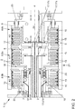
- the Fig. 1 and 2 show, at least partially, schematically in section a multiple clutch 1 for a motor vehicle that is essentially not shown in detail, in particular for a hybrid drive of a motor vehicle that is not shown in detail.
- the following statements basically refer to both in the Fig. 1 and 2 illustrated embodiments.
- the multiple clutch 1 has at least a first separating clutch K1, a second separating clutch K2 and a third separating clutch K0.
- the first, second and third separating clutches K1, K2 and K0 are designed in particular as multi-plate clutches or as friction clutches.
- the multiple clutch 1 shown here is designed or implemented in particular as a double clutch 1a with an attached so-called “K0 clutch” as a third separating clutch.
- the multiple clutch 1 or double clutch 1a shown here with an attached “K0 clutch” is used in particular to control the two transmission input shafts 2 and 3 of a double clutch transmission (not shown in detail), namely a first transmission input shaft 2 and a second transmission input shaft 3.
- the first separating clutch K1 is provided for coupling and / or decoupling the first transmission input shaft 2 with a drive 4 or 5, in particular with an internal combustion engine 4 and / or with an electric machine 5.
- the internal combustion engine 4 and the electric machine 5 are essentially only roughly schematically illustrated or roughly indicated here.
- the second separating clutch K2 is provided for coupling or decoupling the second transmission input shaft 3 with a drive 4 or 5, in particular with the aforementioned internal combustion engine 4 and / or with the aforementioned electric machine 5.
- the first and second separating clutches K1 and K2 are each designed as a multi-disc clutch and each have an inner disc carrier 6 or 7 and an outer disc carrier 8a or 8b.
- the third separating clutch K0 which can also be referred to as a so-called “K0 clutch”, is used to couple or decouple the outer disk carrier 8a or 8b of the first and second separating clutch K1 and K2 with the drive 4 or 5, in particular for coupling or decoupling with the internal combustion engine 4 is provided.
- the third separating clutch K0 is designed as a multi-plate clutch and has an inner plate carrier 9 and an outer plate carrier 8c, the outer plate carrier 8a, 8b and 8c of the first, second and third separating clutches K1, K2 and K0 as a common outer plate carrier 8 for receiving, mounting, Power transmission and / or guidance of the outer plates 10, 11 and 12 of the first, second and third separating clutch K1, K2, K0 is formed.
- the common outer disk carrier 8 has a continuous toothing, not shown in detail here, which is formed in particular on the inner circumference of the common outer disk carrier 8 essentially over the entire axial length of the outer disk carrier 8 or has essentially continuous axial grooves.
- the outer disks 10, 11 and 12 can essentially be pushed individually sequentially one after the other into the common outer disk carrier 8 from one side and received and / or positioned there.
- the outer disks 10, 11 and 12 of the first, second and third separating clutches K1, K2 and K0 can be made essentially the same and / or have the same dimensions.
- the outer disks 10, 11 and 12 can be designed as identical steel disks, so that the manufacturing process for the manufacture of the outer disks 10, 11 and 12 is standardized, in particular, simplified and optimized in this way.
- first, second and third separating clutches K1, K2 and K0 each have a separate inner disk carrier 6, 7 and 9.
- the toothings of the inner disk carriers 6, 7 and 9, not shown here, are essentially of the same design and / or have the same dimensions, so that the respective inner disks 13, 14 and 15 of the first, second and third separating clutches K1, K2 and K0 are also essentially are designed the same and / or have the same dimensions.
- the inner disks 13, 14 and 15 are designed as identically designed facing disks. This also optimizes, simplifies or optimizes the manufacturing process in a correspondingly cost-effective manner.
- the first, second and third clutches K1, K2 and K0 each have corresponding outer disks 10, 11 and 12 or respective inner disks 13, 14 and 15.
- spring elements 16 are now provided which are in the Fig. 1 and 2 are arranged essentially in the vicinity of the outer diameter of the outer disks 10, 11, 12, in particular the steel disks, and can also be seen.
- the spring elements 16 of the first, second and / or separating clutches K1, K2 and K0 are essentially of the same design and / or have the same dimensions. In particular, this is realized or achieved by the same design and / or dimensioning of the respective outer disks 10, 11 and 12 or inner disks 13, 14 and 15 of the separating clutches K1, K2 and K0 as well as by the common outer disk carrier 8.
- a cooling oil feed 17 is provided.
- a separate cooling oil supply 17a, 17b and 17c can be provided or implemented for each separating clutch K1, K2 and K0, as in FIG Fig. 2 shown.
- the first separate cooling oil supply 17a is provided or formed essentially within the first transmission input shaft 2 and the second separate cooling oil supply 17b is essentially provided or formed within or adjacent to the second transmission input shaft 3.
- a third separate cooling oil supply 17c for the third separating clutch K0 is correspondingly provided or configured, in particular a cooling oil duct (not shown) provided within the first transmission input shaft 2 is also configured for this purpose.
- a cooling oil feed 17 is also implemented for the third separating clutch K0, this is designed as a "split cooling oil flow" of the first separate cooling oil feed 17a for the first separating clutch K1.
- the size of a divided flow of cooling oil can also be controlled using orifices that may be provided.
- the embodiment shown therefore has a cooling oil feed 17 with essentially two separate cooling oil feeds 17a and 17b, the first separate cooling oil feed 17a supplying the first and third separating clutches K1 and K0 and the second separate cooling oil feed 17b feeding the second separating clutch K2.
- each of the separating clutches K1, K2 and K0 is supplied by a respective separate cooling oil supply 17a, 17b and 17c, as shown or seen.
- the middle separating clutch in particular the first separating clutch K1
- the middle separating clutch can be actuated by an actuating piston 18 which is at least partially supported and / or guided within the inner disk carrier 7 of an adjacent separating clutch, in particular the second separating clutch K2.
- This embodiment is in Fig. 2 shown.
- Fig. 2 shows the first, second and third separating clutches K1, K2 and K0.
- the preferred embodiment shown here has the actuating piston 18 mounted here within the inner disk carrier 7 of the second separating clutch K2 has a "double bearing", in particular a first and second bearing 19 and 20, so that with the aid of the first and second bearings 19 and 20 one on the actuating piston 18 by the first and the second separating clutch K1 and K2 acting rotary movement are correspondingly decoupled from one another.
- the actuating piston 18 can be axially, in particular slightly axially displaced, so that a simple and structurally cost-effective mounting and / or actuation of the actuating piston 18 within the inner disk carrier 7 is possible.
- the common outer disk carrier 8 is in particular also designed as a rotor carrier 21 and is not related to it illustrated rotor of an electric machine 5, only indicated schematically, effectively connected or connectable.
- the electric machine 5 can apply a corresponding torque to the common outer disk carrier 8 or the rotor carrier 21 formed in this way with the aid of the rotor of the electric machine 5, not shown in detail here, or transmit a corresponding effective torque to the common outer disk carrier 8.
- a drive shaft 4a of an internal combustion engine 4 which is only shown schematically here, is effectively connected or can be connected to the inner disk carrier 9 of the third separating clutch K0. This is in the Fig.
- the first and second separating clutches K1 and K2 are actuated by a respective actuating piston Fig. 2 can be actuated by the actuating pistons 18 and 22, in particular from one side of the outer disc carrier 8, and the third separating clutch K0 can be actuated by an actuating piston 23 from the other side of the outer disc carrier 8.
- the in Fig. 1 The illustrated embodiment of the actuating piston 18 of the first separating clutch K1 is "actuated" here essentially in the inner area, namely essentially via the separate hydraulic pressure system 24 provided here, which is formed with the aid of corresponding channels in the first transmission input shaft 2.
Landscapes
- Engineering & Computer Science (AREA)
- General Engineering & Computer Science (AREA)
- Mechanical Engineering (AREA)
- Chemical & Material Sciences (AREA)
- Combustion & Propulsion (AREA)
- Transportation (AREA)
- Hydraulic Clutches, Magnetic Clutches, Fluid Clutches, And Fluid Joints (AREA)
- Hybrid Electric Vehicles (AREA)
Description
- Die Erfindung betrifft eine Mehrfach-Kupplung für ein Kraftfahrzeug, insbesondere für einen Hybridantrieb eines Kraftfahrzeuges gemäß den Merkmalen des Oberbegriffes des Patentanspruches 1.
- Mehrfach-Kupplungen für Kraftfahrzeuge, insbesondere auch für Hybridantriebe von Kraftfahrzeugen sind in einer Vielzahl im Stand der Technik bereits bekannt.
- Im Allgemeinen weisen derartige Mehrfach-Kupplungen eine erste, eine zweite und eine dritte Trennkupplung auf, die insbesondere als Reib-Lamellen-Kupplungen ausgebildet sind. Hierbei ist die erste Trennkupplung zur Kopplung oder Entkopplung einer - ersten - Getriebeeingangswelle mit einem Antrieb, insbesondere mit einer Verbrennungskraftmaschine und/oder mit einer Elektromaschine vorgesehen. Insbesondere bei Doppelkupplungsgetrieben ist dann eine zweite Trennkupplung vorgesehen, die zur Kopplung oder zur Entkopplung der dann vorgesehenen zweiten Getriebeeingangswelle mit einem Antrieb, insbesondere mit einer Verbrennungskraftmaschine oder mit einer Elektromaschine, vorgesehen ist. Hierbei sind die erste und die zweite Trennkupplung im Wesentlichen jeweils als eine Lamellenkupplung ausgebildet und weisen einen Innen- und Außenlamellenträger bzw. entsprechende Innen-und Außenlamellen auf. Schließlich dient die dritte Trennkupplung zur Kopplung oder zur Entkopplung des Außenlamellenträgers der ersten und zweiten Trennkupplung mit einem Antrieb, insbesondere mit einer Verbrennungskraftmaschine und/oder mit einer Elektromaschine, bzw. ist die dritte Trennkupplung, die auch als sogenannte "K0-Kupplung" bezeichenbar ist, insbesondere zur Auswahl des auf die erste oder zweite Trennkupplung wirkenden Antriebs, insbesondere zur Realisierung des Verbrennungskraftmaschinenantriebs vorgesehen.
- So ist aus der
DE 10 2011 120 809 A1 ein Mehrfach-Kupplungssystem bekannt, das eine erste, zweite und dritte Trennkupplung aufweist, wobei die erste und die zweite Trennkupplung jeweils einen separaten Innen- und Außenlamellenträger aufweisen. Weiterhin weist dieses Mehrfach-Kupplungssystem zur Kühlung der drei Trennkupplungen ein entsprechendes Kühlölsystem auf. Das Kühlölsystem ist so ausgeführt, dass zunächst eine gemeinsame Kühlölzuführung sich im weiteren Verlauf dann in eine ersten und in eine zweiten Strömungspfad aufteilt, wobei der erste Strömungspfad die erste und die zweite Trennkupplung und der zweite Strömungspfad die dritte Trennkupplung entsprechend mit Kühlöl versorgt. Vorzugsweise eignet sich das hier beschriebene Mehrfach-Kupplungssystem für ein Doppelkupplungsgetriebe bzw. ist im Wesentlichen insbesondere als Doppelkupplung mit einer ersten und zweiten Trennkupplung bzw. einer angliederten dritten Trennkupplung (K0-Kupplung) ausgeführt. - Weiterhin ist aus der
DE 11 2007 002 842 T5 eine Mehrfach-Kupplung für ein Kraftfahrzeug bekannt, wobei die insbesondere als Doppelkupplung ausgeführte Mehrfach-Kupplung, nämlich hier die erste und zweite Trennkupplung einen Innen- und Außenlamellenträger aufweisen. Hierbei ist der Außenlamellenträger der ersten Kupplung zugleich als Innenlamellenträger der zweiten Trennkupplung ausgebildet. Schließlich ist auch ein Kühlölsystem vorgesehen, wobei über zwei getrennt voneinander vorgesehene Zuführungskanäle einerseits die erste Trennkupplung, andererseits die zweite Trennkupplung mit Kühlöl versorgbar ist. - Schließlich ist aus der
DE 10 2010 003 442 A1 eine Mehrfach-Kupplung für ein Kraftfahrzeug bekannt, wo eine erste, eine zweite und eine dritte Trennkupplung einen Außenlamellenträger aufweisen und der Außenlamellenträger der ersten, der zweiten und der dritten Trennkupplung als ein gemeinsamer Außenlamellenträger ausgebildet ist. Zumindest zwei der hier vorgesehenen bzw. vorhandenen Trennkupplungen sind radial beabstandet voneinander bzw. radial beabstandet zueinander angeordnet. Der gesamte Aufbau dieser Mehrfach-Kupplung ist komplex und aufwendig. - Die im Stand der Technik bekannten Mehrfach-Kupplungen bzw. Mehrfach-Kupplungssysteme sind noch nicht optimal ausgebildet. Einerseits ist der Konstruktions-und Montageaufwand für die bekannten Mehrfach-Kupplungen erhöht, insbesondere müssen teils für die erste und zweite Trennkupplung sowie auch für die dritte Trennkupplung unterschiedliche Lamellen, insbesondere unterschiedlich ausgebildete und/oder unterschiedlich dimensionierte Reiblamellen hergestellt werden, die auch in mehreren Montageschritten entsprechend angeordnet bzw. positioniert werden müssen. Dies führt zu einem hohen Kostenaufwand. Weiterhin sind die Kühlölsysteme bei den bereits bekannten Mehrfach-Kupplungen bzw. Mehrfach-Kupplungssystemen noch nicht optimal. Aufgrund der komplexen räumlichen Anordnungen der jeweiligen Innen- und Außenlamellenträger der ersten, zweiten und dritten Trennkupplung müssen teils komplexe Kühlölkanäle ausgebildet bzw. realisiert werden, was wiederum die Herstellungskosten entsprechend erhöht.
- Der Erfindung liegt daher die Aufgabe zugrunde die eingangs genannte Mehrfach-Kupplung nun derart auszugestalten und weiterzubilden, dass der Konstruktions- und Montageaufwand und insbesondere die damit im Zusammenhang stehenden Kosten verringert sind, insbesondere auch die Realisierung eines Kühlölsystems vereinfacht ist.
- Die zuvor aufgezeigte Aufgabe ist nun für die eingangs genannte Mehrfach-Kupplung zunächst durch die Merkmale des Patentanspruches 1 gelöst.
- Zunächst ist die dritte Trennkupplung als Lamellenkupplung ausgebildet und weist einen Innen- und einen Außenlamellenträger auf, wobei nun aber der Außenlamellenträger der ersten, der zweiten und der dritten Trennkupplung als ein gemeinsamer Außenlamellenträger zur Aufnahme, Lagerung und/oder Führung der Außenlamellen der ersten, zweiten und dritten Trennkupplung ausgebildet ist. Anders ausgedrückt, es ist nur ein Außenlamellenträger, nämlich ein gemeinsamer Außenlamellenträger für die erste, zweit und dritte Trennkupplung vorgesehen. Hierdurch sind nun mehrere Vorteile realisierbar. Insbesondere weist der gemeinsame Außenlamellenträger eine durchgängige Verzahnung auf, nämlich insbesondere am Innenumfang im Wesentlichen über die axiale Länge des Außenlamellenträgers durchgehende Axialnuten. Hierdurch bedingt ist der Montageaufwand zur Anordnung der Außenlamellen erheblich verringert bzw. vereinfacht, nämlich die entsprechenden Außenlamellen der ersten, zweiten und dritten Trennkupplung können jeweils sequenziell hintereinander in die Axialnuten des gemeinsamen Außenlamellenträger eingeschoben und an den entsprechenden Stellen, wie gewünscht, positioniert werden.
- Durch die Ausbildung der ersten, zweiten und dritten Trennkupplung mit einem gemeinsamen Außenlamellenträger können insbesondere die Außenlamellen, insbesondere Außenlamellen aus Stahl der ersten, zweiten und dritten Trennkupplung im Wesentlichen gleich ausgebildet und/oder gleich dimensioniert werden. Der Herstellungsaufwand und die Herstellungskosten sind erheblich verringert.
- Die erste, zweite und dritte Trennkupplung weisen jeweils einen separaten Innenlamellenträger auf, wobei aber nun die Verzahnungen der jeweiligen Innenlamellenträger im Wesentlichen gleich ausgebildet und/oder gleich dimensioniert sind. Hierdurch bedingt können nun im Wesentlichen auch die Innenlamellen, insbesondere Belaglamellen der ersten, zweiten und dritten Trennkupplung gleich ausgebildet und/oder gleich dimensioniert werden. Auch hierdurch sind daher der Herstellungsaufwand und die damit verbundenen Kosten erheblich verringert.
- Zwischen den einzelnen Lamellen der jeweiligen Trennkupplung, insbesondere zwischen den Außenlamellen der ersten, zweiten und/oder dritten Trennkupplung sind Federelemente vorgesehen, insbesondere um im unbelasteten Zustand der jeweiligen Trennkupplung die Innen- und Außenlamellen dieser jeweiligen Trennkupplung voneinander weg zu bewegen bzw. ein mögliches Schleppmoment zu minimieren. Aufgrund der Ausbildung und/oder der Anordnung der Außenlamellen in einem gemeinsamen Außenlamellenträger können nun auch die Federelemente der ersten, zweiten und/oder dritten Trennkupplung im Wesentlichen gleich ausgebildet und/oder gleich dimensioniert werden. Hierdurch sind wiederum der Montage- und Herstellungsaufwand und die damit verbundenen Kosten entsprechend verringert.
- Insbesondere ist für jede Trennkupplung, also für die erste, zweite und dritte Trennkupplung eine Kühlölzuführung vorgesehen, insbesondere für jede Trennkupplung eine separate Kühlölzuführung vorgesehen bzw. realisiert. Aufgrund der im Wesentlichen sequenziell hintereinander bzw. parallel angeordneten Innen- und Außenlamellen der ersten, zweiten und dritten Trennkupplung und der im Wesentlichen koaxial zu den Innen-und Außenlamellen angeordneten ersten und zweiten Getriebeeingangswelle bzw. der koaxial angeordneten Antriebswelle eines Verbrennungsmotors, was im Folgenden noch näher erläutert werden wird, ist die Ausbildung von Kühlölkanälen, die im Wesentlichen innerhalb der jeweiligen Getriebeeingangswelle verlaufen sehr kostengünstig herstellbar.
- Aufgrund der Anordnung der ersten, zweiten und dritten Trennkupplung, die im Wesentlichen hintereinander liegend angeordnet sind, wobei die mittlere Trennkupplung, insbesondere die erste Trennkupplung durch einen Betätigungskolben betätigbar ist, der zumindest teilweise innerhalb des Innenlamellenträgers einer benachbarten Trennkupplung, insbesondere der zweiten Trennkupplung gelagert und/oder geführt ist, kann der erforderliche Bauraum entsprechend minimiert werden.
- Bei der entsprechend oben angesprochenen Anordnung des Betätigungskolbens, weist der Betätigungskolben eine "Doppellagerung" auf, so dass eine auf den Betätigungskolben durch die erste und zweite Trennkupplung einwirkende Drehbewegung voneinander entkoppelt sind. Dadurch ist eine axiale Verschiebung des Betätigungskolbens mit einem geringen Kraftaufwand ermöglicht bzw. gewährleistet, was wiederum die Betätigung des Betätigungskolbens entsprechend vereinfacht.
- Insbesondere ist der gemeinsame Außenlamellenträger der ersten, zweiten und dritten Trennkupplung als ein Rotorträger ausgebildet und mit dem Rotor einer Elektromaschine wirksam verbindbar oder verbunden. Die so ausgebildete Mehrfach-Kupplung lässt sich daher im Wesentlichen "im Inneren" einer Elektromaschine anordnen, insbesondere auch aufgrund des zuvor oben beschriebenen geringen Bauraumbedarfs.
- Insbesondere wird die Antriebswelle einer Verbrennungskraftmaschine mit dem Innenlamellenträger der dritten Trennkupplung, der sogenannten "K0-Kupplung" wirksam verbunden oder ist hiermit entsprechend wirksam verbindbar. Die dritte Trennkupplung bzw. die "K0-Kupplung" verbindet daher den gemeinsamen Außenlamellenträger insbesondere drehwirksam mit der Antriebswelle einer Verbrennungskraftmaschine oder entkoppelt den gemeinsamen Außenlamellenträger von dieser Antriebswelle.
- Eine einfache Ansteuerung der Betätigung der ersten, zweiten und dritten Trennkupplung ist dadurch gewährleistet, dass die erste und zweite Trennkupplung insbesondere durch einen jeweiligen Betätigungskolben von der einen Seite (Stirnseite) des Außenlamellenträgers her und die dritte Trennkupplung (K0-Kupplung) durch einen Betätigungskolben von der anderen Seite (Stirnseite) des Außenlamellenträgers her betätigbar ist bzw. die entsprechenden jeweiligen Komponenten an der einen oder anderen Stirnseite lagerbar und/oder anordenbar sind.
- Im Ergebnis sind die eingangs genannten Nachteile vermieden und entsprechende Vorteile sind erzielt.
- Es gibt nun eine Vielzahl von Möglichkeiten, die erfindungsgemäße Mehrfach-Kupplung für ein Kraftfahrzeug in vorteilhafter Art und Weise auszugestalten und weiterzubilden. Hierfür darf zunächst auf die dem Patentanspruch 1 nachgeordneten Patentansprüche verwiesen werden. Im Folgenden dürfen mehrere bevorzugte Ausgestaltungen der Erfindung anhand der Zeichnung und der dazugehörigen Beschreibung näher erläutert werden. In der Zeichnung zeigt:
- Fig. 1
- eine Ausführungsform einer Mehrfach-Kupplung in einer vereinfachten schematischen Darstellung, teilweise geschnitten, mit Darstellung der wesentlichen Komponenten, und
- Fig. 2
- eine Ausführungsform einer erfindungsgemäßen Mehrfach-Kupplung in einer vereinfachten schematischen Darstellung, teilweise geschnitten, mit Darstellung der wesentlichen Komponenten.
- Die
Fig. 1 und2 zeigen zumindest teilweise schematisch im Schnitt eine Mehrfach-Kupplung 1 für ein im Wesentlichen nicht näher dargestelltes Kraftfahrzeug, insbesondere für einen Hybridantrieb eines nicht näher dargestellten Kraftfahrzeuges. Die folgenden Ausführungen beziehen sich grundsätzlich auf beide in denFig. 1 und2 dargestellten Ausführungsformen. - Die Mehrfach-Kupplung 1 weist mindestens eine erste Trennkupplung K1, eine zweite Trennkupplung K2 und eine dritte Trennkupplung K0 auf. Die erste, zweite und dritte Trennkupplung K1, K2 und K0 sind insbesondere als Lamellenkupplungen bzw. als Reibkupplungen ausgebildet.
- Die hier dargestellte Mehrfach-Kupplung 1 ist insbesondere als Doppelkupplung 1a mit einer angliederten sogenannten "K0-Kupplung" als dritte Trennkupplung ausgebildet bzw. ausgeführt. Die hier dargestellte Mehrfach-Kupplung 1 bzw. dargestellte Doppelkupplung 1a mit angegliederter "K0-Kupplung" dient insbesondere zur Ansteuerung der beiden Getriebeeingangswellen 2 bzw. 3 eines nicht im einzelnen dargestellten Doppelkupplungsgetriebes, nämlich einer ersten Getriebeeingangswelle 2 und einer zweiten Getriebeeingangswelle 3.
- Die erste Trennkupplung K1 ist zur Kopplung und/oder Entkopplung der ersten Getriebeeingangswelle 2 mit einem Antrieb 4 bzw. 5, insbesondere nämlich mit einer Verbrennungskraftmaschine 4 und/oder mit einer Elektromaschine 5 vorgesehen. Die Verbrennungskraftmaschine 4 und die Elektromaschine 5 sind hier nur im Wesentlichen nur grob schematisch dargestellt bzw. grob angedeutet.
- Die zweite Trennkupplung K2 ist zur Kopplung oder Entkopplung der zweiten Getriebeeingangswelle 3 mit einem Antrieb 4 bzw. 5, insbesondere nämlich mit der bereits zuvor genannten Verbrennungskraftmaschine 4 und/oder mit der bereits zuvor genannten Elektromaschine 5 vorgesehen.
- Die erste und zweite Trennkupplung K1 und K2 sind jeweils als Lamellenkupplung ausgeführt und weisen jeweils einen Innenlamellenträger 6 bzw. 7 und einen Außenlamellenträger 8a bzw. 8b auf.
- Die dritte Trennkupplung K0, die insbesondere auch als sogenannte "K0-Kupplung" bezeichenbar ist, ist zur Kopplung oder Entkopplung des Außenlamellenträgers 8a bzw. 8b der ersten und zweiten Trennkupplung K1 und K2 mit dem Antrieb 4 bzw. 5, hier insbesondere nämlich zur Kopplung oder Entkopplung mit der Verbrennungskraftmaschine 4 vorgesehen.
- Die dritte Trennkupplung K0 ist als Lamellenkupplung ausgebildet und weist einen Innenlamellenträger 9 und einen Außenlamellenträger 8c auf, wobei nun der Außenlamellenträger 8a, 8b und 8c der ersten, zweiten und dritten Trennkupplung K1, K2 und K0 als ein gemeinsamer Außenlamellenträger 8 zur Aufnahme, Lagerung, Kraftübertragung und/oder Führung der Außenlamellen 10, 11 und 12 der ersten, zweiten und dritten Trennkupplung K1, K2, K0 ausgebildet ist.
- Durch die Ausbildung eines gemeinsamen Außenlamellenträgers 8, der insbesondere entsprechende jeweilige Bereiche "8a, 8b und 8c" aufweist, die dann - quasi - als Außenlamellenträger-Bereiche für die Außenlamellen 10, 11 und 12 der jeweiligen ersten, zweiten und dritten Trennkupplung K1, K2 und K0 dienen, werden entscheidende Vorteile erzielt bzw. realisiert, so dass der Konstruktions- und Montageaufwand und die damit verbundenen Kosten entsprechend verringert sind.
- Zunächst weist der gemeinsame Außenlamellenträger 8 eine durchgängige, hier nicht im einzelnen dargestellte Verzahnung auf, die insbesondere am Innenumfang des gemeinsamen Außenlamellenträgers 8 im Wesentlichen über die gesamte axiale Länge des Außenlamellenträgers 8 ausgebildet ist bzw. im wesentlichen durchgehende Axialnuten aufweist. Hierdurch bedingt können die Außenlamellen 10, 11 und 12 im Wesentlichen von einer Seite einzeln sequenziell nacheinander in den gemeinsamen Außenlamellenträger 8 eingeschoben und dort aufgenommen und/oder positioniert werden. Hierbei können die Außenlamellen 10, 11 und 12 der ersten, zweiten und dritten Trennkupplung K1, K2 und K0 im Wesentlichen gleich ausgebildet und/oder gleich dimensioniert ausgeführt werden. Insbesondere können die Außenlamellen 10, 11 und 12 als identische Stahllamellen ausgebildet werden, so dass der Herstellungsprozess für die Herstellung der Außenlamellen 10, 11 und 12 vereinheitlicht, insbesondere damit vereinfacht und kostengünstig optimiert ist.
- Weiterhin weisen die erste, zweite und dritte Trennkupplung K1, K2 und K0 jeweils einen separaten Innenlamellenträger 6, 7 und 9 auf. Die hier nicht dargestellten Verzahnungen der Innenlamellenträger 6, 7 und 9 sind im Wesentlichen gleich ausgebildet und/oder gleich dimensioniert, so dass im Wesentlichen auch die jeweiligen Innenlamellen 13, 14 und 15 der ersten, zweiten und dritten Trennkupplung K1, K2 und K0 im Wesentlichen gleich ausgebildet und/oder gleich dimensioniert ausgeführt sind. Insbesondere sind die Innenlamellen 13, 14 und 15 als identisch ausgebildete Belaglamellen ausgebildet. Auch hierdurch ist der Herstellungsprozess optimiert, vereinfacht bzw. entsprechend kostengünstig optimiert.
- Wie insbesondere aus den
Fig. 1 und2 ersichtlich ist, weisen die erste, zweite und dritte Kupplung K1, K2 und K0 jeweils entsprechende Außenlamellen 10, 11 und 12 bzw. jeweilige Innenlamellen 13, 14 und 15 auf. Zwischen den Lamellen (10, 11, 12 bzw. 13, 14, 15), insbesondere zwischen den Außenlamellen 10, 11 und 12 der ersten, zweiten und/oder dritten Trennkupplung K1, K2 und K0 sind nun Federelemente 16 vorgesehen, die in denFig. 1 und2 im Wesentlichen in der Nähe des Außendurchmessers der Außenlamellen 10, 11, 12, insbesondere der Stahllamellen angeordnet sind, sowie ersichtlich. Hierbei sind die Federelemente 16 der ersten, zweiten und/oder Trennkupplung K1, K2 bzw. K0 im Wesentlichen gleich ausgebildet und/oder gleich dimensioniert. Insbesondere wird dies durch die gleiche Ausbildung und/oder Dimensionierung der jeweiligen Außenlamellen 10, 11 und 12 bzw. Innenlamellen 13, 14 und 15 der Trennkupplungen K1, K2 und K0 sowie durch den gemeinsamen Außenlamellenträger 8 realisiert bzw. erzielt. - Die zuvor beschriebenen Ausführungen gelten im Wesentlichen für die in den
Fig. 1 und2 dargestellten Ausführungsformen. - Weiterhin gilt im Wesentlichen für die in den
Fig. 1 und2 gezeigten Ausführungsformen, dass insbesondere für jede Trennkupplung, nämlich für die erste, zweite und dritte Trennkupplung K1, K2 und K0 eine Kühlölzuführung 17 vorgesehen ist. Insbesondere kann für jede Trennkupplung K1, K2 und K0 eine separate ausgebildete Kühlölzuführung 17a, 17b und 17c vorgesehen bzw. realisiert sein, so wie inFig. 2 gezeigt. - Hierbei ist in
Fig. 2 ist eine erste separate Kühlölzuführung 17a über entsprechende nicht näher bezeichnete Kühlölkanäle für die erste Trennkupplung K1 bzw. eine zweite separate Kühlölzuführung 17b über nicht näher bezeichnete Kühlölkanäle für die zweite Trennkupplung K2 vorgesehen. Hierbei ist die erste separate Kühlölzuführung 17a im Wesentlichen innerhalb der ersten Getriebeeingangswelle 2 und die zweite separate Kühlölzuführung 17b im Wesentlichen innerhalb bzw. angrenzend an die zweite Getriebeeingangswelle 3 vorgesehen bzw. ausgebildet. Bei der inFig. 2 dargestellten Ausführungsform ist eine dritte separate Kühlölzuführung 17c für die dritte Trennkupplung K0 entsprechend vorgesehen bzw. ausgebildet, insbesondere hierfür auch ein innerhalb der ersten Getriebeeingangswelle 2 vorgesehener, nicht näher bezeichneter Kühlölkanal ausgebildet. Hingegen ist bei der inFig. 1 dargestellten Ausführungsform zwar auch für die dritte Trennkupplung K0 eine Kühlölzuführung 17 realisiert, diese ist jedoch als ein "geteilter Kühlölstrom" der ersten separaten Kühlölzuführung 17a für die erste Trennkupplung K1 ausgebildet. Die Größe eines geteilten Kühlölstromes lässt sich auch über möglicherweise vorgesehene Blenden steuern. Die inFig. 1 gezeigte Ausführungsform weist daher eine Kühlölzuführung 17 mit im Wesentlichen zwei separaten Kühlölzuführungen 17a und 17b auf, wobei die erste separate Kühlölzuführung 17a die erste und dritte Trennkupplung K1 und K0 versorgt und die zweite separate Kühlölzuführung 17b die zweite Trennkupplung K2 versorgt. Hingegen wird bei der inFig. 2 gezeigten Ausführungsform jede der Trennkupplungen K1, K2 und K0 durch eine jeweilige separate Kühlölzuführung 17a, 17b und 17c versorgt, so wie dargestellt bzw. ersichtlich. - Wie die
Fig. 1 und2 zeigen sind die erste, zweite und dritte Trennkupplung K1, K2 und K0 im Wesentlichen hintereinander liegend angeordnet, wobei bei der inFig. 2 dargestellten Ausführungsform die mittlere Trennkupplung, insbesondere die erste Trennkupplung K1 durch einen Betätigungskolben 18 betätigbar ist, der zumindest teilweise innerhalb des Innenlamellenträgers 7 einer benachbarten Trennkupplung, insbesondere der zweiten Trennkupplung K2 gelagert und/oder geführt ist. Diese Ausführungsform ist inFig. 2 dargestellt. Bei der inFig. 2 dargestellten bevorzugten Ausführungsform weist der hier innerhalb des Innenlamellenträgers 7 der zweiten Trennkupplung K2 gelagerte Betätigungskolben 18 eine "Doppellagerung" auf, insbesondere ein erstes und zweites Lager 19 und 20, so dass mit Hilfe des ersten und zweiten Lagers 19 und 20 eine auf dem Betätigungskolben 18 durch die erste und die zweite Trennkupplung K1 und K2 einwirkende Drehbewegung voneinander entsprechend entkoppelt sind. Hierdurch bedingt kann der Betätigungskolben 18 axial, insbesondere leicht axial verschoben werden, so dass eine einfache und konstruktiv kostengünstige Lagerung und/oder Betätigung des Betätigungskolbens 18 innerhalb des Innenlamellenträgers 7 ermöglicht ist. - Wie die
Fig. 1 und2 weiter zeigen ist der gemeinsame Außenlamellenträger 8 insbesondere auch als ein Rotorträger 21 ausgebildet und mit dem nicht näher dargestellten Rotor einer nur schematisch angedeuteten Elektromaschine 5 wirksam verbunden oder verbindbar. Anders ausgedrückt, die Elektromaschine 5 kann ein entsprechendes Drehmoment auf den gemeinsamen Außenlamellenträger 8 bzw. den so ausgebildeten Rotorträger 21 mit Hilfe des hier nicht im einzelnen dargestellten Rotors der Elektromaschine 5 aufbringen bzw. ein entsprechendes wirksames Drehmoment auf den gemeinsamen Außenlamellenträger 8 übertragen. Weiterhin ist eine Antriebswelle 4a einer hier nur schematisch dargestellten Verbrennungskraftmaschine 4 mit dem Innenlamellenträger 9 der dritten Trennkupplung K0 wirksam verbunden oder verbindbar. Dies ist in denFig. 1 und2 im Wesentlichen auf der rechten Seite ersichtlich dargestellt, wo im Wesentlichen die Antriebswelle 4a der Verbrennungskraftmaschine 4 ersichtlich ist bzw. wirksam mit dem Innenlamellenträger 9 der dritten Trennkupplung K0 verbunden ist. Bei den hier in denFig. 1 und2 dargestellten Ausführungsformen koppelt bzw. entkoppelt daher die dritte Trennkupplung K0 den gemeinsamen Außenlamellenträger 8 mit der Antriebswelle 4a der Verbrennungskraftmaschine 4. - Weiterhin ist aus den
Fig. 1 und2 ersichtlich, dass die erste und zweite Trennkupplung K1 und K2 durch einen jeweiligen Betätigungskolben, beiFig. 2 durch die Betätigungskolben 18 und 22 insbesondere von der einen Seite des Außenlamellenträgers 8 und die dritte Trennkupplung K0 durch einen Betätigungskolben 23 von der anderen Seite des Außenlamellenträgers 8 betätigbar ist. So wird bei der inFig. 1 dargestellten Ausführungsform der Betätigungskolben 18 der ersten Trennkupplung K1 hier im Wesentlichen im inneren Bereich liegend "betätigt", nämlich im Wesentlichen über das hier vorgesehene separate Hydraulik-Drucksystem 24, das mit Hilfe von entsprechenden Kanälen in der ersten Getriebeeingangswelle 2 ausgebildet ist. -
- 1
- Mehrfach-Kupplung
- 1a
- Doppelkupplung
- 2
- erste Getriebeeingangswelle
- 3
- zweite Getriebeeingangswelle
- 4
- Verbrennungskraftmaschine
- 4a
- Antriebswelle
- 5
- Elektromaschine
- 6
- Innenlamellenträger
- 7
- Innenlamellenträger
- 8
- gemeinsamer Außenlamellenträger
- 8a
- Außenlamellenträger bzw. Außenlamellenträgerbereich für Trennkupplung K1
- 8b
- Außenlamellenträger bzw. Außenlamellenträgerbereich für Trennkupplung K2
- 8c
- Außenlamellenträger bzw. Außenlamellenträgerbereich für Trennkupplung K0
- 9
- Innenlamellenträger
- 10
- Außenlamellen
- 11
- Außenlamellen
- 12
- Außenlamellen
- 13
- Innenlamellen
- 14
- Innenlamellen
- 15
- Innenlamellen
- 16
- Federelemente
- 17
- Kühlölzuführung
- 17a
- erste Kühlölzuführung
- 17b
- zweite Kühlölzuführung
- 17c
- dritte Kühlölzuführung
- 18
- Betätigungskolben
- 19
- erstes Lager
- 20
- zweites Lager
- 21
- Rotorträger
- 22
- Betätigungskolben
- 23
- Betätigungskolben
- 24
- Hydraulik-Drucksystem
- K1
- erste Trennkupplung
- K2
- zweite Trennkupplung
Claims (8)
- Mehrfach-Kupplung (1) für ein Kraftfahrzeug, insbesondere für einen Hybridantrieb eines Kraftfahrzeuges, mit mindestens einer ersten, einer zweiten und einer dritten Trennkupplung (K1, K2, K0), wobei die erste Trennkupplung (K1) zur Kopplung oder Entkopplung einer ersten Getriebeeingangswelle (2) mit einem Antrieb (4 bzw. 5), insbesondere mit einer Verbrennungskraftmaschine (4) und/oder mit einer Elektromaschine (5), und die zweite Trennkupplung (K2) zur Kopplung oder Entkopplung einer zweiten Getriebeeingangswelle (3) mit einem Antrieb (4 bzw. 5), insbesondere mit einer Verbrennungskraftmaschine (4) und/oder mit einer Elektromaschine (5), vorgesehen ist, wobei die erste und zweite Trennkupplung (K1, K2) als Lamellenkupplung ausgeführt sind und einen Innen- (6, 7) und Außenlamellenträger (8a, 8b) aufweisen, wobei die dritte Trennkupplung (K0) zur Kopplung oder Entkopplung des Außenlamellenträgers (8a, 8b) der ersten und zweiten Trennkupplung (K1, K2) mit einem Antrieb (4 bzw. 5), insbesondere mit einer Verbrennungskraftmaschine (4) und/oder mit einer Elektromaschine (5), vorgesehen ist, wobei die dritte Trennkupplung (K0) als Lamellenkupplung ausgebildet ist und einen Innen- (9) und Außenlamellenträger (8c) aufweist und wobei der Außenlamellenträger (8a, 8b, 8c) der ersten, der zweiten und der dritten Trennkupplung (K1, K2, K0) als ein gemeinsamer Außenlamellenträger (8) zur Aufnahme, Lagerung und/oder Führung der Außenlamellen (10, 11, 12) der ersten, zweiten und dritten Trennkupplung (K1, K2, K0) ausgebildet ist, dadurch gekennzeichnet, dass die erste, zweite und dritte Trennkupplung K1, K2, K0) im Wesentlichen hintereinanderliegend angeordnet sind, wobei die mittlere Trennkupplung, insbesondere die erste Trennkupplung (K1), durch einen Betätigungskolben (18) betätigbar ist, der zumindest teilweise innerhalb des Innenlamellenträgers (7) einer benachbarten Trennkupplung, insbesondere der zweiten Trennkupplung (K2), gelagert und/oder geführt ist und dass der Betätigungskolben (18) eine Doppellagerung aufweist, so dass eine auf den Betätigungskolben (18) durch die erste und zweite Trennkupplung (K1, K2) einwirkende Drehbewegung voneinander entkoppelt sind.
- Mehrfach-Kupplung nach dem vorhergehenden Anspruch, dadurch gekennzeichnet, dass der gemeinsame Außenlamellenträger (8) eine durchgängige Verzahnung aufweist, insbesondere am Innenumfang im Wesentlichen über die Länge des Außenlamellenträgers (8) durchgehende Axialnuten vorgesehen sind.
- Mehrfach-Kupplung nach einem der Ansprüche 1 oder 2, dadurch gekennzeichnet, dass die Außenlamellen (10, 11, 12) der ersten, der zweiten und der dritten Trennkupplung (K1, K2, K0) im Wesentlichen gleich ausgebildet und/oder gleich dimensioniert ausgeführt sind.
- Mehrfach-Kupplung nach einem der Ansprüche 1 bis 3, dadurch gekennzeichnet, dass die erste, zweite und dritte Trennkupplung (K1, K2, K0) jeweils einen separaten Innenlamellenträger (6, 7, 9) aufweisen, wobei die Verzahnungen der Innenlamellenträger (6, 7, 9) im Wesentlichen gleich ausgebildet und/oder gleich dimensioniert sind, so dass im Wesentlichen auch die Innenlamellen (13, 14, 15) der ersten, der zweiten und der dritten Trennkupplung (K1, K2, K0) im Wesentlichen gleich ausgebildet und/oder gleich dimensioniert ausgeführt sind.
- Mehrfach-Kupplung nach einem der Ansprüche 1 bis 4, dadurch gekennzeichnet, dass zwischen den Lamellen, insbesondere den Außenlamellen (10, 11, 12) der ersten, zweiten, und/oder dritten Trennkupplung (K1, K2, K0) Federelemente (16) vorgesehen sind, insbesondere wobei die Federelemente (16) der ersten, zweiten und/oder dritten Trennkupplung (K1, K2, K0) im Wesentlichen gleich ausgebildet und/oder gleich dimensioniert sind.
- Mehrfach-Kupplung nach einem der Ansprüche 1 bis 5, dadurch gekennzeichnet, dass für jede Trennkupplung, nämlich für die erste, zweite und dritte Trennkupplung (K1, K2, K0) eine Kühlölzuführung (17) vorgesehen ist, insbesondere für jede Trennkupplung (K1, K2, K0) eine separat ausgebildete Kühlölzuführung (17a, 17b, 17c) vorgesehen bzw. realisiert ist.
- Mehrfach-Kupplung nach einem der Ansprüche 1 bis 6, dadurch gekennzeichnet, dass der gemeinsame Außenlamellenträger (8) als Rotorträger (21) ausgebildet ist und mit dem Rotor einer Elektromaschine (5) wirksam verbunden oder verbindbar ist, wobei eine Antriebswelle (4a) einer Verbrennungskraftmaschine (4) mit dem Innenlamellenträger (9) der dritten Trennkupplung (K0) wirksam verbunden oder verbindbar ist.
- Mehrfach-Kupplung nach einem der Ansprüche 1 bis 7, dadurch gekennzeichnet, dass die erste und zweite Trennkupplung (K1, K2) durch einen Betätigungskolben (18, 22) von der einen Seite des Außenlamellenträgers (8) und die dritte Trennkupplung (K0) durch einen Betätigungskolben (23) von der anderen Seite des Außenlamellenträgers (8) betätigbar ist.
Applications Claiming Priority (2)
| Application Number | Priority Date | Filing Date | Title |
|---|---|---|---|
| DE102016216722.7A DE102016216722A1 (de) | 2016-09-05 | 2016-09-05 | Mehrfach-Kupplung für ein Kraftfahrzeug, insbesondere für einen Hybridantrieb eines Kraftfahrzeugs |
| PCT/EP2017/066651 WO2018041443A1 (de) | 2016-09-05 | 2017-07-04 | Mehrfach-kupplung für ein kraftfahrzeug, insbesondere für einen hybridantrieb eines kraftfahrzeugs |
Publications (2)
| Publication Number | Publication Date |
|---|---|
| EP3507518A1 EP3507518A1 (de) | 2019-07-10 |
| EP3507518B1 true EP3507518B1 (de) | 2021-02-24 |
Family
ID=59285210
Family Applications (1)
| Application Number | Title | Priority Date | Filing Date |
|---|---|---|---|
| EP17735504.7A Active EP3507518B1 (de) | 2016-09-05 | 2017-07-04 | Mehrfach-kupplung für ein kraftfahrzeug, insbesondere für einen hybridantrieb eines kraftfahrzeugs |
Country Status (4)
| Country | Link |
|---|---|
| EP (1) | EP3507518B1 (de) |
| CN (1) | CN109642622B (de) |
| DE (1) | DE102016216722A1 (de) |
| WO (1) | WO2018041443A1 (de) |
Families Citing this family (6)
| Publication number | Priority date | Publication date | Assignee | Title |
|---|---|---|---|---|
| DE102016219693A1 (de) | 2016-10-11 | 2018-04-12 | Schaeffler Technologies AG & Co. KG | Kupplungseinrichtung |
| DE102016223277A1 (de) | 2016-11-24 | 2018-05-24 | Schaeffler Technologies AG & Co. KG | Kupplungseinrichtung |
| DE102017206215A1 (de) * | 2017-04-11 | 2018-10-11 | Zf Friedrichshafen Ag | Mehrfachkupplungsanordnung, Doppelkupplungsgetriebeanordnung sowie Kraftfahrzeug |
| DE102017127217A1 (de) * | 2017-07-18 | 2019-01-24 | Schaeffler Technologies AG & Co. KG | Hybridmodul mit Drehdurchführung |
| JP7552274B2 (ja) * | 2020-11-13 | 2024-09-18 | マツダ株式会社 | 自動変速機 |
| IT202300021981A1 (it) * | 2023-10-20 | 2025-04-20 | Fpt Ind Spa | Assale/ponte a trazione elettrica migliorato |
Citations (2)
| Publication number | Priority date | Publication date | Assignee | Title |
|---|---|---|---|---|
| DE102014204970A1 (de) * | 2013-10-18 | 2015-04-23 | Ford Global Technologies, Llc | Kupplungsanordnung und Getriebe |
| WO2017156358A1 (en) * | 2016-03-11 | 2017-09-14 | Borgwarner Inc. | Clutch and electric motor |
Family Cites Families (9)
| Publication number | Priority date | Publication date | Assignee | Title |
|---|---|---|---|---|
| EP1568906B1 (de) * | 2004-02-27 | 2008-06-18 | BorgWarner Inc. | Doppelkupplung |
| DE102007003107B4 (de) * | 2006-01-16 | 2011-05-05 | Borgwarner Inc., Auburn Hills | Dreifachkupplung für Hybridantrieb mit Doppelkupplungsgetriebe |
| JP4414996B2 (ja) | 2006-11-21 | 2010-02-17 | 株式会社エクセディ | 複式クラッチ装置 |
| DE102008041887A1 (de) * | 2008-09-09 | 2010-03-11 | Zf Friedrichshafen Ag | Hybridantriebsstrang eines Kraftfahrzeugs |
| DE102008052257B4 (de) * | 2008-10-18 | 2019-10-31 | Volkswagen Ag | Leistungsverzweigtes Getriebe |
| DE102010003442B4 (de) * | 2010-03-30 | 2025-09-04 | Zf Friedrichshafen Ag | Hybridantriebsanordnung |
| DE102011120809A1 (de) | 2011-12-10 | 2013-06-13 | Volkswagen Aktiengesellschaft | Mehrfachkupplungssystem für ein Kraftfahrzeug mit einem Ölkühlsystem |
| DE102012008779B4 (de) * | 2012-04-28 | 2025-02-20 | Volkswagen Aktiengesellschaft | Kupplung |
| DE102014219621A1 (de) * | 2014-09-26 | 2016-03-31 | Volkswagen Aktiengesellschaft | Mehrfachkupplung für ein Kraftfahrzeuggetriebe |
-
2016
- 2016-09-05 DE DE102016216722.7A patent/DE102016216722A1/de not_active Withdrawn
-
2017
- 2017-07-04 EP EP17735504.7A patent/EP3507518B1/de active Active
- 2017-07-04 CN CN201780054437.5A patent/CN109642622B/zh active Active
- 2017-07-04 WO PCT/EP2017/066651 patent/WO2018041443A1/de not_active Ceased
Patent Citations (2)
| Publication number | Priority date | Publication date | Assignee | Title |
|---|---|---|---|---|
| DE102014204970A1 (de) * | 2013-10-18 | 2015-04-23 | Ford Global Technologies, Llc | Kupplungsanordnung und Getriebe |
| WO2017156358A1 (en) * | 2016-03-11 | 2017-09-14 | Borgwarner Inc. | Clutch and electric motor |
Also Published As
| Publication number | Publication date |
|---|---|
| EP3507518A1 (de) | 2019-07-10 |
| CN109642622A (zh) | 2019-04-16 |
| DE102016216722A1 (de) | 2018-03-08 |
| WO2018041443A1 (de) | 2018-03-08 |
| CN109642622B (zh) | 2020-08-25 |
Similar Documents
| Publication | Publication Date | Title |
|---|---|---|
| EP3545608B1 (de) | Kupplungseinrichtung | |
| EP1568906B1 (de) | Doppelkupplung | |
| EP1777426B1 (de) | Doppelkupplung | |
| EP3774424B1 (de) | Hybridantriebsmodul für ein kraftfahrzeug | |
| DE102011009419B4 (de) | Mehrfachkupplungseinrichtung und Antriebsstrang mit einer solchen Mehrfachkupplungseinrichtung | |
| EP3507518A1 (de) | Mehrfach-kupplung für ein kraftfahrzeug, insbesondere für einen hybridantrieb eines kraftfahrzeugs | |
| EP3337998B1 (de) | Kupplungseinrichtung für hybridantrieb | |
| EP2732174B1 (de) | Doppelkupplung | |
| EP2572117B1 (de) | Doppelkupplungsgetriebe für kraftfahrzeuge | |
| DE102010005601A1 (de) | Betätigungsvorrichtung für eine Doppelkupplungsanordnung | |
| DE102018217384A1 (de) | Innenlamellenträger für eine nasslaufende Reibkupplung | |
| EP1826438B1 (de) | Öldruckversorgung für die Doppelkupplung eines Kraftfahrzeuges bzw. Doppelkupplungsgetriebe mit der zuvor genannten Öldruckversorgung | |
| EP3622189B1 (de) | Doppelkupplungseinheit und elektroantrieb mit einer solchen doppelkupplungseinheit | |
| DE102019134622A1 (de) | Kupplungseinrichtung | |
| WO2020216394A1 (de) | Hybridmodul sowie antriebsstrang für ein kraftfahrzeug | |
| DE102004058871C5 (de) | Doppelkupplung | |
| EP2742252B1 (de) | Stator für eine reibungskupplung | |
| DE102019126080A1 (de) | Kupplungsanordnung | |
| EP3826873B1 (de) | Hybridmodul mit eingangswelle mit drehdurchführung sowie betätigungseinrichtung für eine von mehreren kupplungen; sowie antriebsstrang | |
| EP1899629B1 (de) | Doppelkupplungsgetriebe für ein kraftfahrzeug | |
| EP2076685B1 (de) | Kupplung und kupplungsanordnung mit einer solchen kupplung | |
| DE102021126008A1 (de) | Lamellenkupplung mit Sicherungselement zur Sicherung des Stütztrings eines Lamellenpakets | |
| EP3645905B1 (de) | Kupplungsanordnung | |
| EP3969769B1 (de) | Kupplungsvorrichtung, hybridmodul sowie antriebsanordnung für ein kraftfahrzeug | |
| DE102019117059A1 (de) | Hybridmodul sowie Antriebsanordnung für ein Kraftfahrzeug |
Legal Events
| Date | Code | Title | Description |
|---|---|---|---|
| STAA | Information on the status of an ep patent application or granted ep patent |
Free format text: STATUS: UNKNOWN |
|
| STAA | Information on the status of an ep patent application or granted ep patent |
Free format text: STATUS: THE INTERNATIONAL PUBLICATION HAS BEEN MADE |
|
| PUAI | Public reference made under article 153(3) epc to a published international application that has entered the european phase |
Free format text: ORIGINAL CODE: 0009012 |
|
| STAA | Information on the status of an ep patent application or granted ep patent |
Free format text: STATUS: REQUEST FOR EXAMINATION WAS MADE |
|
| 17P | Request for examination filed |
Effective date: 20190405 |
|
| AK | Designated contracting states |
Kind code of ref document: A1 Designated state(s): AL AT BE BG CH CY CZ DE DK EE ES FI FR GB GR HR HU IE IS IT LI LT LU LV MC MK MT NL NO PL PT RO RS SE SI SK SM TR |
|
| AX | Request for extension of the european patent |
Extension state: BA ME |
|
| DAV | Request for validation of the european patent (deleted) | ||
| DAX | Request for extension of the european patent (deleted) | ||
| GRAP | Despatch of communication of intention to grant a patent |
Free format text: ORIGINAL CODE: EPIDOSNIGR1 |
|
| STAA | Information on the status of an ep patent application or granted ep patent |
Free format text: STATUS: GRANT OF PATENT IS INTENDED |
|
| INTG | Intention to grant announced |
Effective date: 20201118 |
|
| GRAS | Grant fee paid |
Free format text: ORIGINAL CODE: EPIDOSNIGR3 |
|
| GRAA | (expected) grant |
Free format text: ORIGINAL CODE: 0009210 |
|
| STAA | Information on the status of an ep patent application or granted ep patent |
Free format text: STATUS: THE PATENT HAS BEEN GRANTED |
|
| AK | Designated contracting states |
Kind code of ref document: B1 Designated state(s): AL AT BE BG CH CY CZ DE DK EE ES FI FR GB GR HR HU IE IS IT LI LT LU LV MC MK MT NL NO PL PT RO RS SE SI SK SM TR |
|
| REG | Reference to a national code |
Ref country code: CH Ref legal event code: EP |
|
| REG | Reference to a national code |
Ref country code: DE Ref legal event code: R096 Ref document number: 502017009484 Country of ref document: DE |
|
| REG | Reference to a national code |
Ref country code: AT Ref legal event code: REF Ref document number: 1364814 Country of ref document: AT Kind code of ref document: T Effective date: 20210315 |
|
| REG | Reference to a national code |
Ref country code: IE Ref legal event code: FG4D Free format text: LANGUAGE OF EP DOCUMENT: GERMAN |
|
| REG | Reference to a national code |
Ref country code: LT Ref legal event code: MG9D |
|
| REG | Reference to a national code |
Ref country code: NL Ref legal event code: MP Effective date: 20210224 |
|
| PG25 | Lapsed in a contracting state [announced via postgrant information from national office to epo] |
Ref country code: BG Free format text: LAPSE BECAUSE OF FAILURE TO SUBMIT A TRANSLATION OF THE DESCRIPTION OR TO PAY THE FEE WITHIN THE PRESCRIBED TIME-LIMIT Effective date: 20210524 Ref country code: LT Free format text: LAPSE BECAUSE OF FAILURE TO SUBMIT A TRANSLATION OF THE DESCRIPTION OR TO PAY THE FEE WITHIN THE PRESCRIBED TIME-LIMIT Effective date: 20210224 Ref country code: NO Free format text: LAPSE BECAUSE OF FAILURE TO SUBMIT A TRANSLATION OF THE DESCRIPTION OR TO PAY THE FEE WITHIN THE PRESCRIBED TIME-LIMIT Effective date: 20210524 Ref country code: PT Free format text: LAPSE BECAUSE OF FAILURE TO SUBMIT A TRANSLATION OF THE DESCRIPTION OR TO PAY THE FEE WITHIN THE PRESCRIBED TIME-LIMIT Effective date: 20210624 Ref country code: GR Free format text: LAPSE BECAUSE OF FAILURE TO SUBMIT A TRANSLATION OF THE DESCRIPTION OR TO PAY THE FEE WITHIN THE PRESCRIBED TIME-LIMIT Effective date: 20210525 Ref country code: FI Free format text: LAPSE BECAUSE OF FAILURE TO SUBMIT A TRANSLATION OF THE DESCRIPTION OR TO PAY THE FEE WITHIN THE PRESCRIBED TIME-LIMIT Effective date: 20210224 Ref country code: HR Free format text: LAPSE BECAUSE OF FAILURE TO SUBMIT A TRANSLATION OF THE DESCRIPTION OR TO PAY THE FEE WITHIN THE PRESCRIBED TIME-LIMIT Effective date: 20210224 |
|
| PG25 | Lapsed in a contracting state [announced via postgrant information from national office to epo] |
Ref country code: PL Free format text: LAPSE BECAUSE OF FAILURE TO SUBMIT A TRANSLATION OF THE DESCRIPTION OR TO PAY THE FEE WITHIN THE PRESCRIBED TIME-LIMIT Effective date: 20210224 Ref country code: NL Free format text: LAPSE BECAUSE OF FAILURE TO SUBMIT A TRANSLATION OF THE DESCRIPTION OR TO PAY THE FEE WITHIN THE PRESCRIBED TIME-LIMIT Effective date: 20210224 Ref country code: LV Free format text: LAPSE BECAUSE OF FAILURE TO SUBMIT A TRANSLATION OF THE DESCRIPTION OR TO PAY THE FEE WITHIN THE PRESCRIBED TIME-LIMIT Effective date: 20210224 Ref country code: RS Free format text: LAPSE BECAUSE OF FAILURE TO SUBMIT A TRANSLATION OF THE DESCRIPTION OR TO PAY THE FEE WITHIN THE PRESCRIBED TIME-LIMIT Effective date: 20210224 Ref country code: SE Free format text: LAPSE BECAUSE OF FAILURE TO SUBMIT A TRANSLATION OF THE DESCRIPTION OR TO PAY THE FEE WITHIN THE PRESCRIBED TIME-LIMIT Effective date: 20210224 |
|
| PG25 | Lapsed in a contracting state [announced via postgrant information from national office to epo] |
Ref country code: IS Free format text: LAPSE BECAUSE OF FAILURE TO SUBMIT A TRANSLATION OF THE DESCRIPTION OR TO PAY THE FEE WITHIN THE PRESCRIBED TIME-LIMIT Effective date: 20210624 |
|
| PG25 | Lapsed in a contracting state [announced via postgrant information from national office to epo] |
Ref country code: SM Free format text: LAPSE BECAUSE OF FAILURE TO SUBMIT A TRANSLATION OF THE DESCRIPTION OR TO PAY THE FEE WITHIN THE PRESCRIBED TIME-LIMIT Effective date: 20210224 Ref country code: CZ Free format text: LAPSE BECAUSE OF FAILURE TO SUBMIT A TRANSLATION OF THE DESCRIPTION OR TO PAY THE FEE WITHIN THE PRESCRIBED TIME-LIMIT Effective date: 20210224 Ref country code: EE Free format text: LAPSE BECAUSE OF FAILURE TO SUBMIT A TRANSLATION OF THE DESCRIPTION OR TO PAY THE FEE WITHIN THE PRESCRIBED TIME-LIMIT Effective date: 20210224 |
|
| REG | Reference to a national code |
Ref country code: DE Ref legal event code: R097 Ref document number: 502017009484 Country of ref document: DE |
|
| PG25 | Lapsed in a contracting state [announced via postgrant information from national office to epo] |
Ref country code: RO Free format text: LAPSE BECAUSE OF FAILURE TO SUBMIT A TRANSLATION OF THE DESCRIPTION OR TO PAY THE FEE WITHIN THE PRESCRIBED TIME-LIMIT Effective date: 20210224 Ref country code: DK Free format text: LAPSE BECAUSE OF FAILURE TO SUBMIT A TRANSLATION OF THE DESCRIPTION OR TO PAY THE FEE WITHIN THE PRESCRIBED TIME-LIMIT Effective date: 20210224 Ref country code: SK Free format text: LAPSE BECAUSE OF FAILURE TO SUBMIT A TRANSLATION OF THE DESCRIPTION OR TO PAY THE FEE WITHIN THE PRESCRIBED TIME-LIMIT Effective date: 20210224 |
|
| PLBE | No opposition filed within time limit |
Free format text: ORIGINAL CODE: 0009261 |
|
| STAA | Information on the status of an ep patent application or granted ep patent |
Free format text: STATUS: NO OPPOSITION FILED WITHIN TIME LIMIT |
|
| PG25 | Lapsed in a contracting state [announced via postgrant information from national office to epo] |
Ref country code: ES Free format text: LAPSE BECAUSE OF FAILURE TO SUBMIT A TRANSLATION OF THE DESCRIPTION OR TO PAY THE FEE WITHIN THE PRESCRIBED TIME-LIMIT Effective date: 20210224 Ref country code: AL Free format text: LAPSE BECAUSE OF FAILURE TO SUBMIT A TRANSLATION OF THE DESCRIPTION OR TO PAY THE FEE WITHIN THE PRESCRIBED TIME-LIMIT Effective date: 20210224 |
|
| 26N | No opposition filed |
Effective date: 20211125 |
|
| PG25 | Lapsed in a contracting state [announced via postgrant information from national office to epo] |
Ref country code: SI Free format text: LAPSE BECAUSE OF FAILURE TO SUBMIT A TRANSLATION OF THE DESCRIPTION OR TO PAY THE FEE WITHIN THE PRESCRIBED TIME-LIMIT Effective date: 20210224 |
|
| REG | Reference to a national code |
Ref country code: CH Ref legal event code: PL |
|
| GBPC | Gb: european patent ceased through non-payment of renewal fee |
Effective date: 20210704 |
|
| PG25 | Lapsed in a contracting state [announced via postgrant information from national office to epo] |
Ref country code: MC Free format text: LAPSE BECAUSE OF FAILURE TO SUBMIT A TRANSLATION OF THE DESCRIPTION OR TO PAY THE FEE WITHIN THE PRESCRIBED TIME-LIMIT Effective date: 20210224 |
|
| REG | Reference to a national code |
Ref country code: BE Ref legal event code: MM Effective date: 20210731 |
|
| PG25 | Lapsed in a contracting state [announced via postgrant information from national office to epo] |
Ref country code: LI Free format text: LAPSE BECAUSE OF NON-PAYMENT OF DUE FEES Effective date: 20210731 Ref country code: IT Free format text: LAPSE BECAUSE OF FAILURE TO SUBMIT A TRANSLATION OF THE DESCRIPTION OR TO PAY THE FEE WITHIN THE PRESCRIBED TIME-LIMIT Effective date: 20210224 Ref country code: GB Free format text: LAPSE BECAUSE OF NON-PAYMENT OF DUE FEES Effective date: 20210704 Ref country code: CH Free format text: LAPSE BECAUSE OF NON-PAYMENT OF DUE FEES Effective date: 20210731 |
|
| PG25 | Lapsed in a contracting state [announced via postgrant information from national office to epo] |
Ref country code: IS Free format text: LAPSE BECAUSE OF FAILURE TO SUBMIT A TRANSLATION OF THE DESCRIPTION OR TO PAY THE FEE WITHIN THE PRESCRIBED TIME-LIMIT Effective date: 20210624 Ref country code: LU Free format text: LAPSE BECAUSE OF NON-PAYMENT OF DUE FEES Effective date: 20210704 Ref country code: FR Free format text: LAPSE BECAUSE OF NON-PAYMENT OF DUE FEES Effective date: 20210731 |
|
| PG25 | Lapsed in a contracting state [announced via postgrant information from national office to epo] |
Ref country code: IE Free format text: LAPSE BECAUSE OF NON-PAYMENT OF DUE FEES Effective date: 20210704 Ref country code: BE Free format text: LAPSE BECAUSE OF NON-PAYMENT OF DUE FEES Effective date: 20210731 |
|
| P01 | Opt-out of the competence of the unified patent court (upc) registered |
Effective date: 20230523 |
|
| PG25 | Lapsed in a contracting state [announced via postgrant information from national office to epo] |
Ref country code: CY Free format text: LAPSE BECAUSE OF FAILURE TO SUBMIT A TRANSLATION OF THE DESCRIPTION OR TO PAY THE FEE WITHIN THE PRESCRIBED TIME-LIMIT Effective date: 20210224 |
|
| PG25 | Lapsed in a contracting state [announced via postgrant information from national office to epo] |
Ref country code: HU Free format text: LAPSE BECAUSE OF FAILURE TO SUBMIT A TRANSLATION OF THE DESCRIPTION OR TO PAY THE FEE WITHIN THE PRESCRIBED TIME-LIMIT; INVALID AB INITIO Effective date: 20170704 |
|
| REG | Reference to a national code |
Ref country code: AT Ref legal event code: MM01 Ref document number: 1364814 Country of ref document: AT Kind code of ref document: T Effective date: 20220704 |
|
| PG25 | Lapsed in a contracting state [announced via postgrant information from national office to epo] |
Ref country code: AT Free format text: LAPSE BECAUSE OF NON-PAYMENT OF DUE FEES Effective date: 20220704 |
|
| PG25 | Lapsed in a contracting state [announced via postgrant information from national office to epo] |
Ref country code: MK Free format text: LAPSE BECAUSE OF FAILURE TO SUBMIT A TRANSLATION OF THE DESCRIPTION OR TO PAY THE FEE WITHIN THE PRESCRIBED TIME-LIMIT Effective date: 20210224 |
|
| PG25 | Lapsed in a contracting state [announced via postgrant information from national office to epo] |
Ref country code: MT Free format text: LAPSE BECAUSE OF FAILURE TO SUBMIT A TRANSLATION OF THE DESCRIPTION OR TO PAY THE FEE WITHIN THE PRESCRIBED TIME-LIMIT Effective date: 20210224 |
|
| PGFP | Annual fee paid to national office [announced via postgrant information from national office to epo] |
Ref country code: DE Payment date: 20250731 Year of fee payment: 9 |
|
| PG25 | Lapsed in a contracting state [announced via postgrant information from national office to epo] |
Ref country code: TR Free format text: LAPSE BECAUSE OF FAILURE TO SUBMIT A TRANSLATION OF THE DESCRIPTION OR TO PAY THE FEE WITHIN THE PRESCRIBED TIME-LIMIT Effective date: 20210224 |