EP3507355B1 - Photobioreaktor und verfahren zur kultivierung von mikroalgen - Google Patents
Photobioreaktor und verfahren zur kultivierung von mikroalgen Download PDFInfo
- Publication number
- EP3507355B1 EP3507355B1 EP17762082.0A EP17762082A EP3507355B1 EP 3507355 B1 EP3507355 B1 EP 3507355B1 EP 17762082 A EP17762082 A EP 17762082A EP 3507355 B1 EP3507355 B1 EP 3507355B1
- Authority
- EP
- European Patent Office
- Prior art keywords
- photobioreactor
- culture medium
- manifold
- liquid
- riser
- Prior art date
- Legal status (The legal status is an assumption and is not a legal conclusion. Google has not performed a legal analysis and makes no representation as to the accuracy of the status listed.)
- Active
Links
Images



Classifications
-
- C—CHEMISTRY; METALLURGY
- C12—BIOCHEMISTRY; BEER; SPIRITS; WINE; VINEGAR; MICROBIOLOGY; ENZYMOLOGY; MUTATION OR GENETIC ENGINEERING
- C12M—APPARATUS FOR ENZYMOLOGY OR MICROBIOLOGY; APPARATUS FOR CULTURING MICROORGANISMS FOR PRODUCING BIOMASS, FOR GROWING CELLS OR FOR OBTAINING FERMENTATION OR METABOLIC PRODUCTS, i.e. BIOREACTORS OR FERMENTERS
- C12M21/00—Bioreactors or fermenters specially adapted for specific uses
- C12M21/02—Photobioreactors
-
- C—CHEMISTRY; METALLURGY
- C12—BIOCHEMISTRY; BEER; SPIRITS; WINE; VINEGAR; MICROBIOLOGY; ENZYMOLOGY; MUTATION OR GENETIC ENGINEERING
- C12M—APPARATUS FOR ENZYMOLOGY OR MICROBIOLOGY; APPARATUS FOR CULTURING MICROORGANISMS FOR PRODUCING BIOMASS, FOR GROWING CELLS OR FOR OBTAINING FERMENTATION OR METABOLIC PRODUCTS, i.e. BIOREACTORS OR FERMENTERS
- C12M23/00—Constructional details, e.g. recesses, hinges
- C12M23/02—Form or structure of the vessel
- C12M23/06—Tubular
-
- C—CHEMISTRY; METALLURGY
- C12—BIOCHEMISTRY; BEER; SPIRITS; WINE; VINEGAR; MICROBIOLOGY; ENZYMOLOGY; MUTATION OR GENETIC ENGINEERING
- C12M—APPARATUS FOR ENZYMOLOGY OR MICROBIOLOGY; APPARATUS FOR CULTURING MICROORGANISMS FOR PRODUCING BIOMASS, FOR GROWING CELLS OR FOR OBTAINING FERMENTATION OR METABOLIC PRODUCTS, i.e. BIOREACTORS OR FERMENTERS
- C12M23/00—Constructional details, e.g. recesses, hinges
- C12M23/34—Internal compartments or partitions
-
- C—CHEMISTRY; METALLURGY
- C12—BIOCHEMISTRY; BEER; SPIRITS; WINE; VINEGAR; MICROBIOLOGY; ENZYMOLOGY; MUTATION OR GENETIC ENGINEERING
- C12M—APPARATUS FOR ENZYMOLOGY OR MICROBIOLOGY; APPARATUS FOR CULTURING MICROORGANISMS FOR PRODUCING BIOMASS, FOR GROWING CELLS OR FOR OBTAINING FERMENTATION OR METABOLIC PRODUCTS, i.e. BIOREACTORS OR FERMENTERS
- C12M29/00—Means for introduction, extraction or recirculation of materials, e.g. pumps
- C12M29/06—Nozzles; Sprayers; Spargers; Diffusers
-
- C—CHEMISTRY; METALLURGY
- C12—BIOCHEMISTRY; BEER; SPIRITS; WINE; VINEGAR; MICROBIOLOGY; ENZYMOLOGY; MUTATION OR GENETIC ENGINEERING
- C12M—APPARATUS FOR ENZYMOLOGY OR MICROBIOLOGY; APPARATUS FOR CULTURING MICROORGANISMS FOR PRODUCING BIOMASS, FOR GROWING CELLS OR FOR OBTAINING FERMENTATION OR METABOLIC PRODUCTS, i.e. BIOREACTORS OR FERMENTERS
- C12M39/00—Means for cleaning the apparatus or avoiding unwanted deposits of microorganisms
-
- C—CHEMISTRY; METALLURGY
- C12—BIOCHEMISTRY; BEER; SPIRITS; WINE; VINEGAR; MICROBIOLOGY; ENZYMOLOGY; MUTATION OR GENETIC ENGINEERING
- C12N—MICROORGANISMS OR ENZYMES; COMPOSITIONS THEREOF; PROPAGATING, PRESERVING, OR MAINTAINING MICROORGANISMS; MUTATION OR GENETIC ENGINEERING; CULTURE MEDIA
- C12N1/00—Microorganisms; Compositions thereof; Processes of propagating, maintaining or preserving microorganisms or compositions thereof; Processes of preparing or isolating a composition containing a microorganism; Culture media therefor
- C12N1/12—Unicellular algae; Culture media therefor
Definitions
- the field of the present invention is that of photobioreactors for cultivating phototrophic microorganisms such as microalgae.
- Phototrophic microorganisms such as microalgae are cultivated primarily because of their valuable ingredients, which are required, for example, in the manufacture of medical preparations, food and feed, food supplements and cosmetics. These ingredients include unsaturated fatty acids (e.g. omega-3 and omega-6 fatty acids), antioxidants such as astaxanthin and lutein, and chlorophyll.
- unsaturated fatty acids e.g. omega-3 and omega-6 fatty acids
- antioxidants such as astaxanthin and lutein
- chlorophyll chlorophyll.
- the composition of the ingredients depends on the cultivated type of phototrophic microorganisms. A pure culture of phototrophic microorganisms is predominantly used in order to be able to guarantee a certain quality or minimum concentration of the desired ingredients.
- the photosynthesizing microorganisms are cultivated under the action of light (e.g. sunlight) in a nutrient-containing culture medium in a photobioreactor, and then concentrated and processed.
- the ingredients can be obtained from the biomass obtained for further processing or the biomass itself can be used, for example, as animal feed or fertilizer.
- a prior art construction of photobioreactors for cultivating phototrophic microorganisms is that of the "vertical tubular reactor", in which upright, parallel, essentially transparent tubes (sometimes also referred to as columns) are connected in series and are mostly flown through in a meandering shape by the culture medium with the phototrophic microorganisms.
- a photobioreactor of this type is, for example, from US 2014/0242681 A1 famous.
- the tubes of a photobioreactor are prone to becoming fouled over time, especially in continuous operation.
- Residues from cultivation for example from the remains of dead microorganisms
- this can reduce the luminous efficiency (since these residues typically absorb light) and, on the other hand, represent a constant risk of contamination of the culture medium with undesirable microorganisms that find a suitable culture medium in the residues.
- the yield from cultivation can, in turn, be significantly reduced as a result of reduced light yield or contamination.
- it can be of great importance for product safety to exclude contamination of the culture with undesirable (and sometimes even toxic) microorganisms as far as possible.
- the WO 2009/051478 A2 relates to a photobioreactor with cleaning system.
- a cleaning tool eg a cylindrical sponge, see also Fig. 2-5 of the document
- the tubes of the photobioreactor are connected as U-shaped connecting pieces (cf. Fig. 1 , Reference number 5 of the document) and not disclosed as fumigated.
- the WO 2015/179888 A1 discloses a vertical type reactor.
- This reactor consists of at least one reactor element, which is formed from at least two upright, connected tubes or chambers, the individual reactor elements having inlet and outlet openings on the underside of the outermost tubes or chambers, the inlet opening each having one against the direction of the Gravity, i.e. a rising branch, and the outlet opening is assigned a branch in the direction of gravity, i.e. a falling branch, so that all connections in the lower area, in particular the inlet opening, the outlet opening and the introduction inlet, are surrounded by the reaction medium.
- Fig. 1 or. Fig. 3 It can be seen from the document that the tubes or chambers in the reactor element are "connected in series" (cf. also p.
- the reactor element is closed on the top with a closure element, wherein the closing element is designed to be removable in order to be able to clean the system (p. 16, 1st paragraph, of the document).
- the state of the art believes that it has found a further solution to the problem outlined above in the "single-use" photobioreactor.
- the reactor components such as pipes are made of comparatively inexpensive plastic material, which can be replaced after a short period of operation.
- a flexible low-density polyethylene (“flexible LDP bag material”) is proposed as the material for the columns or pipes. According to paragraphs [0087] - [0090], if the microalgae culture is in an unfavorable condition, this material is discarded, the U-shaped connecting pieces are separated from the gas distribution pipe and cleaned, for example, in a dishwasher.
- the present invention provides a photobioreactor for cultivating phototrophic microorganisms, with a reactor element which has a plurality of riser and downcomers for liquid culture medium containing the microorganisms and a distributor pipe.
- the ascending and descending pipes are each connected at their upper end to the distribution pipe in a liquid-permeable manner.
- At least one of the riser and one of the downpipes are additionally connected (or connected) to one another by a connecting piece in a liquid-permeable manner.
- the photobioreactor also has a device for introducing gas into at least one riser pipe.
- the photobioreactor is designed in such a way that, in the operating state, both culture medium and, above the culture medium, a gas space for accommodating gas bubbles rising from the culture medium are present in the distribution pipe, an interface between the culture medium and the gas space being arranged in the distribution pipe.
- the invention also provides a method for cultivating phototrophic microorganisms.
- This comprises the exposure of a photobioreactor, the photobioreactor being provided with a reactor element which has a plurality of riser and downcomers for liquid culture medium containing the microorganisms and a distribution pipe, the riser and downcomers each at their upper end are connected to the distribution pipe in a liquid-permeable manner, at least one of the riser and one of the downpipes being additionally connected to each other by a connecting piece in a fluid-permeable manner, and the photobioreactor in the riser and downpipes containing liquid culture medium with the microorganisms, which is at least partially gassed.
- the present invention is based, inter alia, on the knowledge that cleaning or keeping the photobioreactor clean is made considerably easier by the aforementioned interfaces of more difficult to access areas, as it were, in a (more easily accessible) area due to the construction according to the invention or the operation of the photobioreactor according to the invention.
- the distribution pipe is moved and combined there to form an interface.
- One advantage of the meandering flow is that the ripening of the phototrophic microorganisms is more regulated, because microorganisms with similar degrees of ripeness are separated from one another to a lesser extent in the culture medium than would be the case with a more chaotic flow (e.g. if there are turbulences or different flow paths). In this way, microorganisms of a similar degree of ripeness can also be removed more easily from the photobioreactor together.
- a meandering flow of the culture medium through the riser and downpipes is achieved in that the culture medium in the riser connected to the downpipe by the connecting piece is gassed more strongly than in the downpipe.
- pumps which are usually harmful to the phototrophic microorganisms due to the shear forces they cause
- the internal surfaces of the risers and downpipes are kept cleaner due to frequent contact with rising gas bubbles.
- agitation and / or a flow of the culture medium is expediently caused essentially by the gas bubbles rising in the culture medium.
- a device for guiding a maintenance device movable in the distribution pipe is provided on the distribution pipe.
- This can be, for example, a guide rail, a guide wire, or a bar with positioning markings that can be read by the maintenance device.
- the device for guiding is magnetic, it can also be attached to the outside of the distribution pipe.
- the maintenance device can use spray nozzles, brushes and / or wiper blades to free the inner surface of the distribution pipe, in particular in the area of the interface, of any dried-up residues, i.e. clean or keep them clean.
- the inner surface of the distribution pipe is cleaned by the movable maintenance device, preferably at preset time intervals. This advantageously takes place during operation, so that losses in the yield are avoided as far as possible. It is useful here if the maintenance device can be flowed around within the distribution pipe.
- the construction according to the invention enables (higher quality) glass components to be used instead of single-use plastic components, among other things because the risk of glass breakage is reduced if dismantling for cleaning is less often required.
- the ascending and descending pipes and / or the distribution pipe consist essentially of glass.
- this increases the longevity or resistance of the photobioreactor, especially when microalgae are cultivated that require a culture medium with an extreme pH value.
- glass typically becomes less roughened over time than the plastic usually used, so that cleaning or keeping it clean is simplified.
- the glass can be coated, as for example in the DE 10 2009 029 792 A1 or the WO 2011/015653 A2 disclosed.
- a riser pipe connected to the downpipe by the connecting piece is provided Inlet for gassing with the device is provided, and a further inlet for gassing with the device is provided for the downpipe connected to the riser pipe by the connecting piece.
- This enables different levels of gassing to the riser and downpipes. When gassing via the same gas line, this can be achieved, for example, by providing a gassing inlet of the riser with one or more openings (e.g. in the form of membranes or sintered disks) which are overall more permeable than those of the gassing inlet of the downpipe.
- the ascending pipe i.e.
- the gassing inlet of the ascending pipe can be gassed with a pressure A via a first gas line, while the downpipe (ie the gassing inlet of the downcomer) is gassed with a pressure B via a second gas line, where A is greater than B. .
- connection piece can consist (continuously) of more easily machinable, non-transparent materials such as stainless steel.
- the photobioreactor of the present invention is preferably of the tubular reactor type, more specifically, a vertical tubular reactor or not a plate reactor (or flat panel reactor).
- said plurality of riser or downpipes of the reactor element which are connected to the same distribution pipe in a liquid-permeable manner, is at least three (e.g. in the arrangement downpipe - riser - downpipe or riser - downpipe - riser along the distribution pipe).
- the said plurality is at least four, preferably at least five, more preferably at least ten, even more preferably at least twenty, in particular at least thirty or even at least forty.
- An alternating arrangement of riser or downpipes along the distribution pipe is advantageously chosen (e.g. riser - downpipe - riser - ...
- the sum of the flow velocity vectors of the currents of the culture medium prevailing in the distribution pipe advantageously results in a flow velocity vector that is essentially parallel to the longitudinal axis of the distribution pipe (so to speak, a net flow along the longitudinal axis, cf. also the horizontal dashed arrows in Fig. 3 ).
- the longitudinal axes of the ascending or descending pipes optionally independently of one another, at an angle of more than 5 °, preferably more than 20 °, more preferably more than 40 ° or even more than 60 ° more preferably more than 70 ° or even more than 80 °, in particular more than 85 ° or even more than 87.5 ° to the level of the culture medium or to the distribution pipe. It is particularly favorable when the longitudinal axes of the ascending and descending pipes are essentially normal (or normal) to the level of the culture medium or to the (preferably essentially horizontal) distribution pipe (in other words: if these are vertically oriented).
- the longitudinal axes of the ascending and descending pipes are expediently essentially parallel to one another.
- the distribution pipe (“manifold”) has at least three liquid-permeable connections for ascending and descending pipes. These can, for example, be bores, openings or connection extensions (in this case, however, the interface mentioned must be located inside the distribution pipe itself (in other words: in the main pipe of the distribution pipe) to ensure easier cleaning). It is favorable if the distribution pipe along its longitudinal axis does not have a gradient or an incline with an angle (with respect to the level of the culture medium) of more than 10 °, preferably of more than 5 °, more preferably more than 2.5 °, even more preferably more than 1 ° or even more than 0.5 °.
- the distribution pipe is particularly preferably oriented essentially horizontally or horizontally (along its longitudinal axis) (ie its longitudinal axis is essentially parallel or parallel to the level of the culture medium).
- the gas space in the distribution pipe (which is located above the culture medium in the distribution pipe) is preferably a gas space which is located along the longitudinal axis of the distribution pipe for at least 10%, preferably at least 20% or even at least 30%, more preferably at least 40%. or even at least 50%, even more preferably at least 60% or even at least 70%, in particular at least 80% or even at least 90% of the length of the distribution pipe. It is particularly useful if the gas space mentioned extends over the entire length of the distributor pipe. It goes without saying that “gas” can also be understood to mean a gas mixture.
- the distribution pipe and / or the ascending or descending pipes expediently, optionally independently of one another, do not have a bend of more than 90 °, preferably of more than 70 °, more preferably of more than 50 °, along their longitudinal axis. even more preferably of more than 30 ° or even of more than 20 °, in particular of more than 10 ° or even of more than 5 °. It is particularly advantageous if the distribution pipe and / or the ascending or descending pipes are essentially straight or straight along their longitudinal axis.
- the distribution pipe and / or the ascending or descending pipes (possibly with the exception of any connection extensions) preferably have an essentially round profile.
- a connecting piece preferably connects exactly one of the riser pipes to exactly one of the downpipes in a liquid-permeable manner (or connects the two to one another in a liquid-permeable manner). It is preferred here that at least all but one or two riser pipes of the reactor element and / or at least all but one or two downcomers of the reactor element are each connected in pairs to such a connector in a liquid-permeable manner, in particular, at least all but one riser pipe of the reactor element and / or at least all but one downpipe of the reactor element are each connected in pairs to such a connecting piece in a liquid-permeable manner.
- a connecting piece connects a riser pipe and a downpipe which are adjacent to one another (ie are connected to the distribution pipe next to one another) in a liquid-permeable manner.
- “Operating state” is to be understood here as a state of the photobioreactor in which living phototrophic microorganisms are cultivated in culture medium in the photobioreactor, the culture medium in the photobioreactor preferably having a flow (in particular essentially caused by the gassing).
- Embodiment 1 Photobioreactor for the cultivation of phototrophic microorganisms, with a reactor element which has a tube, and with a maintenance device and a drive system that can move the maintenance device in the tube, the photobioreactor being designed in such a way that the tube in the operating state of the photobioreactor of liquid Culture medium with the microorganisms is at least partially flowed through, characterized in that the photobioreactor is designed such that the maintenance device can be used in the operating state of the photobioreactor in the tube and can be moved by the drive system at least against the flow of the culture medium in the tube.
- Embodiment 2 Photobioreactor according to embodiment 1, characterized in that the photobioreactor also has a device for gassing the culture medium, the photobioreactor being designed in such a way that, when the photobioreactor is in operation, the maintenance device in the tube is brought into contact with gas bubbles in the culture medium.
- Embodiment 3 Photobioreactor according to embodiment 1 or 2, characterized in that, in the operating state of the photobioreactor, the maintenance device in the tube for the culture medium can flow around and / or through it.
- Embodiment 4 Photobioreactor according to one of embodiments 1 to 3, characterized in that the photobioreactor is designed in such a way that, in the operating state, both culture medium and, above the culture medium, a gas space for receiving gas bubbles rising from the culture medium are present in the tube, wherein an interface between the culture medium and the gas space is arranged in the tube, and the maintenance device is set up at least for cleaning of the inner surface of the tube which is in contact with the gas space.
- Embodiment 5 Photobioreactor according to one of embodiments 1 to 4, characterized in that the maintenance device has a spray nozzle for spraying the inner surface of the pipe with a cleaning liquid, preferably wherein the maintenance device is at least for spraying the inner surface of the in contact with said gas space Tube is set up by the spray nozzle.
- Embodiment 6 Photobioreactor according to one of embodiments 1 to 5, characterized in that the maintenance device has at least one wiper blade made of an elastic material for wiping the inner surface of the tube, preferably wherein the maintenance device is at least for wiping inner surfaces in contact with said gas space Surface of the tube is set up with the wiper blade and / or preferably wherein the maintenance device has an, optionally further, spray nozzle which is set up for spraying the wiper blade with a cleaning liquid.
- Embodiment 7 Photobioreactor according to embodiment 5 or 6, wherein the spray nozzle is connected via a line to a liquid reservoir outside the tube.
- Embodiment 8 Photobioreactor according to one of embodiments 1 to 8, characterized in that the pipe is a distribution pipe with at least three connections for the inflow or outflow of culture medium, and the photobioreactor is designed such that the maintenance device is connected to at least one of the connections in Pipe can be moved and can seal this.
- Embodiment 9 Photobioreactor according to embodiment 8, characterized in that the reactor element further has a plurality of riser and downcomers for the liquid culture medium, the riser and downcomers each being connected at their upper end to the pipe designed as a distribution pipe in a liquid-permeable manner, wherein at least one of the riser and one of the downpipes are additionally connected to each other by a connecting piece, and the photobioreactor is designed in such a way that the maintenance device simultaneously provides the connection for the downpipe and the connection for the riser, both of which are additionally liquid-permeable to each other by a connecting piece are connected, can seal.
- the reactor element further has a plurality of riser and downcomers for the liquid culture medium, the riser and downcomers each being connected at their upper end to the pipe designed as a distribution pipe in a liquid-permeable manner, wherein at least one of the riser and one of the downpipes are additionally connected to each other by a connecting piece, and the photobioreactor is designed in such a
- Embodiment 10 Photobioreactor according to embodiment 9, characterized in that the maintenance device is set up to clean the downpipe sealed by the maintenance device with respect to the pipe and the ascending pipe sealed with respect to the pipe by the maintenance device, both of which are connected to one another by a connecting piece in a liquid-permeable manner .
- Embodiment 11 Photobioreactor according to one of embodiments 1 to 10, characterized in that a guide bar for stabilizing and / or positioning the maintenance device in the pipe is provided on the pipe, preferably on its outside.
- Embodiment 12 Photobioreactor according to one of embodiments 1 to 11, characterized in that the drive system has at least one cable winch which can drive a cable guided in the pipe and connected to the maintenance device, preferably wherein the cable winch is equipped with a device for disinfecting the cable.
- Embodiment 13 Photobioreactor according to one of embodiments 1 to 12, characterized in that the maintenance device has at least two modules which are connected to one another by a coupling, preferably wherein the tube consists essentially of glass.
- Embodiment 14 Photobioreactor according to one of the embodiments 1 to 13, characterized in that the photobioreactor has a station for the maintenance device which is set up for cleaning the maintenance device and into which the maintenance device can be moved.
- Embodiment 15 A method for culturing phototrophic microorganisms in a photobioreactor, wherein the photobioreactor is equipped with a reactor element having a tube and with a maintenance device in the tube and a drive system that moves the maintenance device in the tube, the tube of liquid culture medium is at least partially traversed by the microorganisms, characterized in that the method includes the use of the maintenance device in the tube in the operating state of the photobioreactor and the maintenance device is moved by the drive system at least against the flow of the culture medium in the tube. preferably wherein the photobioreactor is further defined in accordance with one of embodiments 1 to 11.
- Movable maintenance device for the maintenance of the inner surface of a tube of a photobioreactor for the cultivation of phototrophic microorganisms characterized in that the maintenance device for the maintenance of the inner surface of the tube during operation of the photobioreactor, while the tube of liquid culture medium with the microorganisms at least is partially flowed through, is suitable and is set up for this, by an external drive system, which preferably has a cable winch, at least against the flow of the culture medium in the pipe to be moved.
- Embodiment 17 Movable maintenance device according to embodiment 16, characterized in that the maintenance device comprises a spray nozzle for spraying the inner surface of the pipe with a cleaning liquid and a connection for a line with the liquid.
- Embodiment 18 Movable maintenance device according to embodiment 16 or 17, characterized in that the maintenance device has at least one wiper blade made of an elastic material for wiping the inner surface of the tube, preferably wherein the maintenance device has one, optionally further, spray nozzle which is used for spraying the wiper blade is set up with a cleaning liquid.
- Embodiment 19 Movable maintenance device according to one of the embodiments 16 to 18, characterized in that the maintenance device has at least two modules which are connected to one another by a coupling.
- Embodiment 20 Movable maintenance device according to one of the embodiments 16 to 19, characterized in that the maintenance device is further equipped with a device for sealing connections of the pipe.
- Embodiment 21 Use of the movable maintenance device according to one of the embodiments 16 to 20 for the maintenance of the inner surface of a tube of a photobioreactor for the cultivation of phototrophic microorganisms, the maintenance during operation of the photobioreactor, the tube being at least partially flowed through by liquid culture medium with the microorganisms , he follows.
- Fig. 2 shows a photobioreactor 1 for the cultivation of phototrophic microorganisms, with two reactor elements 2, each of which has a plurality of vertical, straight riser pipes 3a and downpipes 3b for culture medium 4 and a horizontal, straight distributor pipe 5.
- the culture medium 4 is a liquid culture medium based on water and enriched with nutrients; it contains the phototrophic microorganisms (usually microalgae).
- Said pipes are made of glass, the distribution pipes 5 being provided with connection extensions 50 (see also FIG Figures 5A and 5B ).
- the ascending pipes 3a and downpipes 3b are each connected at their upper end 6 with the aid of the pipe connector 51 to the connection extensions 50 of the distribution pipe 5 in a liquid-permeable manner.
- the riser pipes 3a and the downpipes 3b are additionally connected to one another by a U-shaped connecting piece 7 in a liquid-permeable manner (see also FIG Fig. 4 ).
- the photobioreactor 1 also has a device 8 for introducing carbon dioxide (and / or compressed air) into the riser pipes 3a or the down pipes 3b.
- a device 8 for introducing carbon dioxide (and / or compressed air) into the riser pipes 3a or the down pipes 3b For that with the downpipe 3b the riser pipe 3a connected to the connecting piece 7 is provided with an inlet 14a for gassing through the device 8. A further inlet 14b for gassing through the device 8 is provided for the downpipe 3b connected to the ascending pipe 3a by the connecting piece 7.
- the carbon dioxide is pumped from a liquid tank into a gas distribution pipe by a gas pump.
- the connections of the gas distribution pipe are connected by hoses, each with an inlet 14a or 14b.
- This meandering flow is further stabilized by the fact that the two reactor elements 2 are connected to each other via a downpipe 3b of the first reactor element 2 with a riser tube 3a of the second reactor element 2 by a U-shaped connector 7 in a liquid-permeable manner - that is to say, in simplified terms, by providing a "gap""between the two distribution pipes 5.
- the inlet 52a and the outlet 52b can be connected to one another by a hose, as a result of which cyclical operation of the photobioreactor 1 is made possible.
- the culture medium 4 which now contains a significantly higher concentration of microorganisms, can be removed at the outlet 52b for harvesting (ie for the concentration and drying of the phototrophic microorganisms), while fresh culture medium 4 with a low initial concentration of phototrophic microorganisms is introduced.
- a continuous cyclical operation is also conceivable, in which the inlet 52a remains connected to the outlet 52b by a hose, and fresh culture medium 5 is continuously supplied to an inlet in a first lower connection piece 7 and to an outlet in one proceeding from the direction of flow directly in front of the second lower connecting piece 7 continuously the same amount of denser Culture medium 4 is removed.
- a certain minimum length of the breeding route is required for this.
- continuous linear operation is also conceivable, in which fresh culture medium 4 with a low initial concentration of phototrophic microorganisms is continuously introduced at inlet 52a and the same amount of ripe culture medium 4 continuously removed for harvest at outlet 52b will.
- Inlets can, however, also be provided at other points of the reactor (eg U-bend connection piece of the first / last riser or downpipe, but also in another U-bend connection piece in the photobioreactor).
- the meandering flowing culture medium 4 with the phototrophic microorganisms is so high in the reactor elements 2 that the distribution pipes 5 are each about half filled with it.
- the distribution pipe 5 there are both culture medium 4 and, above the culture medium 4, a gas space 9 for receiving gas bubbles 10 rising from the culture medium 4, an interface 11 between the culture medium 4 and the gas space 9 being arranged in the distribution pipe 5.
- the gas pressure equalization with the environment takes place via the valve 53, which is equipped with a filter system in order to avoid contamination of the culture medium 4.
- the contamination on the inner surface of the distribution pipe 5 associated with the interface 11 between the culture medium 4 and the gas space 9 can be cleaned with relatively little effort by briefly taking the photobioreactor 1 out of operation and draining the culture medium 4 from the distribution pipe 5, which Cover plate 54 of the distribution pipe is removed and the inner surface of the distribution pipe is cleaned, for example with a brush attached to a telescopic rod.
- the illustrated embodiment of the photobioreactor 1 enables the inner surface of the distribution pipe 5 to be cleaned or kept clean during operation.
- the guide rail 12 for the movable maintenance device 13 is provided on the distribution pipe 5.
- the maintenance device 13 is provided with brushes and spray nozzles for the inner surface of the Distribution pipe 5 equipped.
- the maintenance device 13 is, for example, magnetic and can be moved by a magnet (or ropes) that can be displaced in the guide rail 12.
- the maintenance device 13 can be flowed around and can be used during ongoing operation at presettable time intervals, which significantly reduces the downtimes of the photobioreactor 1.
- the dashed arrows illustrate the flow path in the reactor element 2.
- Fig. 7 shows schematically an embodiment of the photobioreactor 1 in which the respective distribution pipe 5 of a reactor element 2 consists of glass sections 56 directly connected to one another. In each case two reactor elements 2 are provided by the in Fig. 6 Metal frame 55 shown held.
Landscapes
- Health & Medical Sciences (AREA)
- Life Sciences & Earth Sciences (AREA)
- Engineering & Computer Science (AREA)
- Chemical & Material Sciences (AREA)
- Bioinformatics & Cheminformatics (AREA)
- Organic Chemistry (AREA)
- Zoology (AREA)
- Wood Science & Technology (AREA)
- Biotechnology (AREA)
- Genetics & Genomics (AREA)
- General Engineering & Computer Science (AREA)
- Biomedical Technology (AREA)
- Microbiology (AREA)
- General Health & Medical Sciences (AREA)
- Biochemistry (AREA)
- Sustainable Development (AREA)
- Clinical Laboratory Science (AREA)
- Molecular Biology (AREA)
- Cell Biology (AREA)
- Botany (AREA)
- Medicinal Chemistry (AREA)
- Tropical Medicine & Parasitology (AREA)
- Virology (AREA)
- Apparatus Associated With Microorganisms And Enzymes (AREA)
- Preparation Of Compounds By Using Micro-Organisms (AREA)
- Micro-Organisms Or Cultivation Processes Thereof (AREA)
Description
- Das Gebiet der vorliegenden Erfindung ist das der Photobioreaktoren zur Kultivierung phototropher Mikroorganismen wie beispielsweise Mikroalgen.
- Phototrophe Mikroorganismen wie Mikroalgen werden vor allem ihrer wertvollen Inhaltsstoffe wegen kultiviert, die z.B. in der Herstellung von medizinischen Präparaten, Nahrungs- und Futtermitteln, Nahrungsergänzungsmitteln, und Kosmetika benötigt werden. Zu diesen Inhaltsstoffen gehören unter anderem ungesättigte Fettsäuren (z.B. Omega-3 und Omega-6-Fettsäuren), Antioxidantien wie Astaxanthin und Lutein, und Chlorophyll. Die Zusammensetzung der Inhaltsstoffe ist von der kultivierten Art von phototrophen Mikroorganismen abhängig. Vorwiegend wird eine Reinkultur von phototrophen Mikroorganismen herangezogen, um eine gewisse Qualität bzw. Mindestkonzentration der gewünschte Inhaltsstoffe gewährleisten zu können.
- Üblicherweise werden die Photosynthese betreibenden Mikroorganismen unter Einwirkung von Licht (z.B. Sonnenlicht) im nährstoffhaltigen Kulturmedium in einem Photobioreaktor kultiviert, und anschließend aufkonzentriert und verarbeitet. Aus der erhaltenen Biomasse können die Inhaltsstoffe zur Weiterverarbeitung gewonnen werden bzw. kann die Biomasse selbst z.B. als Futtermittel oder Dünger verwendet werden.
- Eine im Stand der Technik bekannte Bauweise von Photobioreaktoren zur Kultivierung phototropher Mikroorganismen ist die des "vertikalen Rohr-Reaktors" ("vertical tubular reactor"), bei dem aufrechte, parallele, im Wesentlichen transparente Rohre (mitunter auch als Säulen bezeichnet) in Serie geschaltet sind und zumeist mäanderförmig vom Kulturmedium mit den phototrophen Mikroorganismen durchflossen werden. Ein Photobioreaktor dieser Bauweise ist beispielsweise aus der
US 2014/0242681 A1 bekannt. - Im Allgemeinen sind die Rohre eines Photobioreaktors insbesondere im Dauerbetrieb anfällig dafür, mit der Zeit zu verschmutzen. Dabei lagern sich oft Rückstände aus der Kultivierung (beispielsweise aus Überresten toter Mikroorganismen) an der Innenseite der Rohre an. Dies kann zum einen die Lichtausbeute mindern (da diese Rückstände typischerweise Licht absorbieren) und zum anderen eine ständige Gefahr in Bezug auf Kontamination des Kulturmediums mit unerwünschten Mikroorganismen darstellen, die in den Rückständen einen geeigneten Nährboden finden. Durch verminderte Lichtausbeute bzw. Kontamination kann sich wiederum die Ausbeute aus der Kultivierung deutlich verringern. Des weiteren kann es insbesondere für sensible Bereiche wie die Herstellung von medizinischen Präparaten oder Nahrungsergänzungsmitteln von hoher Bedeutung für die Produktsicherheit sein, Kontaminationen der Kultur mit unerwünschten (und mitunter sogar toxischen) Mikroorganismen möglichst auszuschließen.
- Die
WO 2009/051478 A2 betrifft einen Photobioreaktor mit Reinigungssystem. Zwischen Stationen kann ein Reinigungswerkzeug (z.B. ein zylindrischer Schwamm, vgl. auchFig. 2-5 des Dokuments) zur Reinigung der Reaktor-Rohrinnenwände hin und her gepumpt werden (vgl. S. 12, 2. Absatz). Im Dokument sind die Rohre des Photobioreaktors als über U-förmige Verbindungsstücke verbunden (vgl.Fig. 1 , Bezugszeichen 5, des Dokuments) sowie nicht als begast offenbart. - Die
WO 2015/179888 A1 offenbart einen Reaktor des vertikalen Typs. Dieser Reaktor besteht aus mindestens einem Reaktorelement, das aus mindestens zwei aufrechten, verbundenen Röhren oder Kammern gebildet ist, wobei die einzelnen Reaktorelemente an der Unterseite an jeweils den äußersten Röhren oder Kammern Ein- und Auslassöffnungen aufweisen, wobei der Einlassöffnung jeweils eine gegen die Richtung der Schwerkraft, also ein aufsteigender Ast, und der Auslassöffnung eine in Richtung der Schwerkraft, also ein abfallender Ast, zugeordnet ist, dass alle Anschlüsse im unteren Bereich, insbesondere die Einlassöffnung, die Auslassöffnung und der Einbringungseinlass, mit dem Reaktionsmedium umspült sind. AusFig. 1 bzw.Fig. 3 des Dokuments lässt sich entnehmen, dass die Rohre oder Kammern im Reaktorelement "in Serie geschaltet sind" (vgl. auch S. 14, Z 19, des Dokuments), d.h. dass nie mehr als zwei Rohre bzw. Kammern im Reaktorelement als direkt miteinander miteinander verbunden offenbart sind. Gemäß einer Ausgestaltung ist das Reaktorelement an der Oberseite mit einem Abschlusselement verschlossen, wobei das Abschlusselement abnehmbar ausgebildet ist, um die Anlage reinigen zu können (S. 16, 1. Absatz, des Dokuments). - Einen weiteren Lösungsansatz für das oben geschilderte Problem vermeint der Stand der Technik im "Einweg"-Photobioreaktor gefunden zu haben. Bei diesem sind die Reaktorbestandteile wie z.B. Rohre aus vergleichsweise kostengünstigen Kunststoffmaterial gefertigt, das bereits nach kurzem Betrieb wieder ausgetauscht wird.
- So bezieht sich die
US 2011/0027875 A1 auf einen kostengünstigen, vertikalen Photobioreaktor für den Produktionseinsatz. Gemäß den dargestellten Ausführungsformen des Dokuments sind bei diesem Photobioreaktor im wesentlichen vertikal orientierte, parallele, transparente Säulen oder Rohre durch untere und obere U-förmige Verbindungsstücke miteinander verbunden, so dass der Photobioreaktor im Betrieb in einem geschlossenen Kreislauf von Kulturmedium mit Mikroalgen mäanderförmig durchflossen werden kann. Die Rohre bzw. Säulen (bzw. das Kulturmedium darin) werden mit Kohlendioxid begast, welches bekanntlich von den Mikroalgen zu Sauerstoff umgesetzt wird. Die unteren und oberen U-förmigen Verbindungsstücke können jeweils mit einem Gasverteilrohr ("gas manifold") verbunden sein (vgl.Fig. 1 , die den unteren Ausschnitt vonFig. 1 des genannten Dokuments wiedergibt). Als Material für die Säulen oder Rohre wird ein flexibles Polyethylen mit niedriger Dichte ("flexible LDP bag material") vorgeschlagen. Gemäß der Absätze [0087]-[0090] wird bei ungünstigem Zustand der Mikroalgenkultur dieses Material verworfen, die U-förmigen Verbindungsstücke werden vom Gasverteilrohr getrennt und z.B. in einem Geschirrspüler gereinigt. - Diese Herangehensweise an die Reinigung bzw. das Sauberhalten von Photobioreaktoren im Stand der Technik ist mit vielen Nachteilen verbunden, unter anderem verursacht sie (vor allem bei großen Produktionsanlagen) hohen manuellen Arbeitsaufwand und lange Stehzeiten, welche die Ausbeute des Photobioreaktors mit der Zeit schmälern. Des Weiteren wirkt sich der hohe Verbrauch an Material (üblicherweise Kunststoff) nachteilig auf die ökologische Gesamtbilanz des Photobioreaktorbetriebs aus.
- Es ist Aufgabe der vorliegenden Erfindung, die Reinigung bzw. das Sauberhalten eines Photobioreaktors zur Kultivierung phototropher Mikroorganismen zu vereinfachen. Dadurch können die Lebensdauer bzw. Ausbeute des Photobioreaktors erhöht und die Betriebskosten verringert werden.
- Die vorliegende Erfindung stellt einen Photobioreaktor zur Kultivierung phototropher Mikroorganismen, mit einem Reaktorelement, das eine Vielzahl von Steig- und Fallrohren für flüssiges Kulturmedium, welches die Mikroorganismen beinhaltet, und ein Verteilrohr aufweist, zur Verfügung. Die Steig- und Fallrohre sind jeweils an ihrem oberen Ende mit dem Verteilrohr flüssigkeitsdurchlässig verbunden. Zumindest eines der Steig- und eines der Fallrohre sind zusätzlich miteinander durch ein Verbindungsstück flüssigkeitsdurchlässig verbunden (bzw. angeschlossen). Der Photobioreaktor weist ferner eine Einrichtung zum Einleiten von Gas in zumindest ein Steigrohr auf. Erfindungsgemäß ist der Photobioreaktor derart ausgelegt, dass im Betriebszustand im Verteilrohr sowohl Kulturmedium als auch, oberhalb des Kulturmediums, ein Gasraum zur Aufnahme von aus dem Kulturmedium aufsteigenden Gasblasen vorhanden sind, wobei im Verteilrohr eine Grenzfläche zwischen dem Kulturmedium und dem Gasraum angeordnet ist. Dadurch wird die genannte Aufgabe gelöst.
- Dementsprechend stellt die Erfindung auch ein Verfahren zur Kultivierung phototropher Mikroorganismen zur Verfügung. Dieses umfasst das Belichten eines Photobioreaktors, wobei der Photobioreaktor versehen ist mit einem Reaktorelement, das eine Vielzahl von Steig- und Fallrohren für flüssiges Kulturmedium, welches die Mikroorganismen beinhaltet, und ein Verteilrohr aufweist, wobei die Steig- und Fallrohre jeweils an ihrem oberen Ende mit dem Verteilrohr flüssigkeitsdurchlässig verbunden sind, wobei zumindest eines der Steig- und eines der Fallrohre zusätzlich miteinander durch ein Verbindungsstück flüssigkeitsdurchlässig verbunden sind, und wobei der Photobioreaktor in den Steig- und Fallrohren flüssiges Kulturmedium mit den Mikroorganismen beinhaltet, welches zumindest teilweise begast wird. Im Verteilrohr sind sowohl flüssiges Kulturmedium mit den Mikroorganismen als auch, oberhalb des Kulturmediums, ein Gasraum vorhanden, wobei im Verteilrohr eine Grenzfläche zwischen dem Kulturmedium und dem Gasraum ausgebildet wird, und der Gasraum aus dem Kulturmedium aufsteigende Gasblasen aufnimmt. Auch dadurch wird die genannte Aufgabe gelöst.
- Es hat sich während der Entwicklung der vorliegenden Erfindung herausgestellt, dass gerade die mit der Grenzfläche zwischen Kulturmedium und Gasraum in Berührung befindlichen Innenoberflächen eines Photobioreaktors (bzw. der "Grenzflächenraum" in der näheren Umgebung der Grenzfläche) anfällig für Verschmutzungen sind, wobei sich mit der Dauer des Betriebes üblicherweise immer mehr Verschmutzungen anlagern. Im Bereich der Grenzfläche (die oft über die Betriebsdauer geringfügig in der Höhe variiert) kann es immer wieder zu Schaumbildung und Antrocknungen von Rückständen der phototrophen Mikroorganismen kommen. Insbesondere wenn eine Begasung des Photobioreaktors vorgesehen ist, lässt sich das Vorkommen solcher verschmutzungsanfälligen Grenzflächen (bzw. Grenzflächenräume) im Photobioreaktor kaum vermeiden. Zusätzlich verursachen die aus dem Kulturmedium aufsteigenden Gasblasen, dass die Innenoberfläche des Photobioreaktors mit Kulturmedium bespritzt wird und diese Spritzer über die Zeit ebenfalls antrocknen und dadurch Verschmutzungen bilden. Wenn sich die genannten Grenzflächen, wie in
Fig. 1 gezeigt (siehe insbesondere die obersten gebogenen Pfeile inFig. 1 ), an schwieriger zugänglichen Bereichen befindet, bleibt zur Reinigung oft nichts als die vorübergehende Demontage des Photobioreaktors, wie z.B. in derUS 2011/0027875 A1 offenbart. - Die vorliegende Erfindung beruht nun unter anderem auf der Erkenntnis, dass die Reinigung bzw. das Sauberhalten des Photobioreaktors wesentlich erleichtert wird, indem die genannten Grenzflächen von schwieriger zugänglichen Bereichen durch die erfindungsgemäße Bauweise bzw. den erfindungsgemäßen Betrieb des Photobioreaktors sozusagen in ein (leichter zugängliches) Verteilrohr verschoben und dort zu einer Grenzfläche zusammengefasst werden.
- Es hat sich unerwarteterweise herausgestellt, dass im erfindungsgemäßen Photobioreaktor dennoch eine mäanderförmige Strömung aufrecht erhalten werden kann, obwohl im Stand der Technik zur Gewährleistung der mäanderförmigen Strömung üblicherweise U-förmige Verbindungsstücke sowohl am oberen als auch am unteren Ende der Steig- bzw. Fallrohre vorgesehen werden (vgl. z.B. die
US 2014/0242681 A1 oder dieUS 2011/0027875 A1 ). Daher werden in einer bevorzugten Ausführungsform des erfindungsgemäßen Verfahrens die Steig- und Fallrohre mäanderförmig vom Kulturmedium durchströmt. Ein Vorteil der mäanderförmigen Strömung ist, dass die Reifung der phototrophen Mikroorganismen geregelter abläuft, weil Mikroorganismen ähnlichen Reifegrades im Kulturmedium in geringeren Ausmaß voneinander abgeschieden als dies bei chaotischerer Strömung der Fall wäre (z.B. wenn Turbulenzen oder verschiedene Strömungspfade vorhanden sind). So können Mikroorganismen ähnlichen Reifegrades auch einfacher gemeinsam aus dem Photobioreaktor entnommen werden. - Als besonders vorteilhaft für die Stabilisierung der mäanderförmigen Strömung hat sich erwiesen, wenn im Photobioreaktor zumindest zwei Reaktorelemente vorgesehen sind, wobei ein Fallrohr des ersten Reaktorelements mit einem Steigrohr des zweiten Reaktorelements miteinander durch ein Verbindungsstück flüssigkeitsdurchlässig verbunden sind.
- In einer bevorzugten Ausführung wird im Betriebszustand eine mäanderförmige Strömung des Kulturmediums durch die Steig- und Fallrohre dadurch erreicht, dass das Kulturmedium im mit dem Fallrohr durch das Verbindungsstück verbundenen Steigrohr stärker begast wird als in dem Fallrohr. Es kann in diesem Zusammenhang auch von einem "Gaslift"-Effekt gesprochen werden. Ein Vorteil dieser Ausführung ist, dass im Betrieb auf Pumpen (die für die phototrophen Mikroorganismen durch die von ihnen verursachten Scherkräfte üblicherweise schädlich sind) zumindest weitgehend verzichtet werden kann. Ein weiterer Vorteil besteht darin, dass die inneren Oberflächen der Steig- bzw. Fallrohre durch den häufigen Kontakt mit aufsteigenden Gasblasen sauberer gehalten werden.
- Zweckmäßigerweise wird also im Betriebszustand des Photobioreaktors eine Agitation und/oder ein Fluss des Kulturmediums im Wesentlichen durch die im Kulturmedium aufsteigenden Gasblasen verursacht.
- In einer besonders bevorzugten Ausführungsform ist am Verteilrohr eine Einrichtung zur Führung einer im Verteilrohr beweglichen Instandhaltungsvorrichtung vorgesehen. Dabei kann es sich beispielsweise um eine Führungsschiene, einen Führungsdraht, oder eine Leiste mit Positionierungsmarkierungen, die von der Instandhaltungsvorrichtung abgelesen werden können, handeln. Insbesondere wenn die Einrichtung zur Führung magnetisch ist, kann sie auch auf der Außenseite des Verteilrohres angebracht sein. Die Instandhaltungsvorrichtung kann die innere Oberfläche des Verteilrohres, insbesondere im Bereich der Grenzfläche, mit Hilfe von Sprühdüsen, Bürsten und/oder Wischblättern von gegebenenfalls eingetrockneten Rückständen befreien, d.h. reinigen bzw. sauberhalten.
- In einer bevorzugten Ausführung des erfindungsgemäßen Verfahrens wird die innere Oberfläche des Verteilrohres von der beweglichen Instandhaltungsvorrichtung, vorzugsweise in voreinstellbaren Zeitabständen, gereinigt. Vorteilhafterweise geschieht dies während des Betriebes, so dass Einbußen bei der Ausbeute möglichst vermieden werden. Dabei ist es zweckmäßig, wenn die Instandhaltungsvorrichtung innerhalb des Verteilrohres umströmbar ist.
- Durch die erfindungsgemäße Bauweise wird ermöglicht, dass statt Einweg-Kunststoffkomponenten (hochwertigere) Glasbauteile verwendet werden können, unter anderem auch weil das Risiko für Glasbruch sinkt, wenn eine Demontage zur Reinigung weniger oft erforderlich ist. Somit bestehen in einer bevorzugten Ausführungsform des Photobioreaktors die Steig- und Fallrohre und/oder das Verteilrohr im Wesentlichen aus Glas. Dadurch wird unter anderem die Langlebigkeit bzw. Widerstandsfähigkeit des Photobioreaktors erhöht, insbesondere wenn Mikroalgen kultiviert werden, die ein Kulturmedium mit extremem pH-Wert benötigen. Hinzu kommt, dass sich Glas typischerweise mit der Zeit weniger aufraut als der üblicherweise verwendete Kunststoff, so dass die Reinigung bzw. das Sauberhalten vereinfacht wird. Das Glas kann beschichtet sein, wie beispielsweise in der
DE 10 2009 029 792 A1 oder derWO 2011/015653 A2 offenbart. - Gemäß einer weiteren bevorzugten Ausführungsform ist für das mit dem Fallrohr durch das Verbindungsstück verbundene Steigrohr ein Einlass zur Begasung mit der Einrichtung vorgesehen, und für das mit dem Steigrohr durch das Verbindungsstück verbundene Fallrohr ein weiterer Einlass zur Begasung mit der Einrichtung vorgesehen. Dadurch kann eine unterschiedlich starke Begasung der Steig- und Fallrohre ermöglicht werden. Bei Begasung über dieselbe Gasleitung kann dies z.B. durch Vorsehen eines Begasungseinlasses des Steigrohres mit einer oder mehreren Öffnungen (z.B. in Form von Membranen oder gesinterten Scheiben), die insgesamt durchlässiger sind als die des Begasungseinlasses des Fallrohres, erreicht werden. Alternativ kann das Steigrohr (d.h. der Begasungseinlass des Steigrohres) z.B. über eine erste Gasleitung mit einem Druck A begast werden, während das Fallrohr (d.h. der Begasungseinlass des Fallrohres) über eine zweite Gasleitung mit einem Druck B begast wird, wobei A größer als B ist.
- Es ist besonders günstig, wenn zumindest einer der Einlässe zur Begasung im Verbindungsstück vorgesehen ist, weil dies im Aufbau des Photobioreaktors leichter zu bewerkstelligen ist. Das Verbindungsstück kann nämlich (durchgehend) aus leichter bearbeitbaren, intransparenten Materialien wie z.B. Edelstahl bestehen.
- Der Photobioreaktor der vorliegenden Erfindung ist vorzugsweise vom Typ her ein Rohrreaktor ("tubular reactor"), genauer gesagt ein vertikaler Rohrreaktor ("vertical tubular reactor"), bzw. kein Plattenreaktor ("plate reactor" bzw. "flat panel reactor").
- Erfindungsgemäß beträgt die genannte Vielzahl von Steig- bzw. Fallrohren des Reaktorelements, die mit dem selben Verteilrohr flüssigkeitsdurchlässig verbunden sind, zumindest drei (z.B. in der Anordnung Fallrohr - Steigrohr - Fallrohr oder Steigrohr - Fallrohr - Steigrohr entlang des Verteilrohres). Es ist im Sinne der Skalierbarkeit der Reinigung günstig, wenn die genannte Vielzahl zumindest vier, bevorzugt zumindest fünf, mehr bevorzugt zumindest zehn, noch mehr bevorzugt zumindest zwanzig, insbesondere zumindest dreißig oder gar zumindest vierzig beträgt. Vorteilhafterweise wird eine alternierende Anordnung von Steig- bzw. Fallrohren entlang des Verteilrohres gewählt (also z.B. Steigrohr - Fallrohr - Steigrohr - ... - Fallrohr - Steigrohr oder Steigrohr - Fallrohr - Steigrohr - ... - Fallrohr - Steigrohr - Fallrohr, oder Fallrohr - Steigrohr - Fallrohr - ... - Steigrohr). Zweckmäßigerweise ist die Positionierung von Ein- bzw. Auslässen (z.B. am oberen oder unteren Ende) im Photobioreaktor natürlich gemäß dieser Anordnung so zu wählen, dass ein Totvolumen vermieden wird. Für den Fachmann ist evident, dass durch Umdrehen des Flusses des Kulturmediums (z.B. durch Änderung der Begasung) ein Steigrohr zu einem Fallrohr werden kann bzw. umgekehrt. Vorteilhafterweise ergibt sich aus der Summe der Flussgeschwindigkeitsvektoren der im Verteilrohr herrschenden Strömungen des Kulturmediums (insbesondere wenn im Reaktorelement eine mäanderförmige Strömung geführt wird) ein Flussgeschwindigkeitsvektor, der im Wesentlichen parallel zur Längsachse des Verteilrohres ist (sozusagen eine Netto-Strömung entlang der Längsachse, vgl. auch die horizontalen gestrichelten Pfeile in
Fig. 3 ). - Es ist günstig, wenn die Längsachsen der Steig- bzw. Fallrohre, gegebenenfalls unabhängig voneinander, in einem Winkel von mehr als 5°, bevorzugt von mehr als 20°, mehr bevorzugt von mehr als 40° oder gar von mehr als 60°, noch mehr bevorzugt von mehr als 70° oder gar von mehr als 80°, insbesondere von mehr als 85° oder gar von mehr als 87,5° zum Spiegel des Kulturmediums bzw. zum Verteilrohr stehen. Besonders günstig ist, wenn die Längsachsen der Steig- bzw. Fallrohre im Wesentlichen normal (bzw. normal) zum Spiegel des Kulturmediums bzw. zum (bevorzugt im Wesentlichen horizontalen) Verteilrohr stehen (mit anderen Worten: wenn diese vertikal orientiert sind). Zweckmäßigerweise sind die Längsachsen der Steig- und Fallrohre (insbesondere derer, die jeweils durch ein Verbindungsstück verbunden sind) zueinander im Wesentlichen parallel.
- Das Verteilrohr ("Manifold") weist gemäß der erfindungsgemäßen Definition zumindest drei flüssigkeitsdurchlässige Anschlüsse für Steig- bzw. Fallrohre auf. Diese können z.B. als Bohrungen, Öffnungen oder Anschlussfortsätze (die genannte Grenzfläche muss diesfalls jedoch im Inneren des Verteilrohres selbst (mit anderen Worten: im Hauptrohr des Verteilrohres) verortet sein, um eine vereinfachte Reinigung sicherzustellen) ausgebildet sein. Es ist günstig, wenn das Verteilrohr entlang seiner Längsachse kein Gefälle bzw. keine Steigung mit einem Winkel (in Bezug auf den Spiegel des Kulturmediums) von mehr als 10°, bevorzugt von mehr als 5°, mehr bevorzugt von mehr als 2,5°, noch mehr bevorzugt von mehr als 1° oder gar von mehr als 0,5° aufweist. Besonders bevorzugt ist das Verteilrohr (entlang seiner Längsachse) im Wesentlichen horizontal oder horizontal orientiert (d.h. seine Längsachse ist im Wesentlichen parallel bzw. parallel zum Spiegel des Kulturmediums).
- Im Kontext der Erfindung ist der Gasraum im Verteilrohr (der sich oberhalb des Kulturmediums im Verteilrohr befindet) bevorzugt ein Gasraum, der sich entlang der Längsachse des Verteilrohres über zumindest 10%, bevorzugt zumindest 20% oder gar zumindest 30%, mehr bevorzugt zumindest 40% oder gar zumindest 50%, noch mehr bevorzugt zumindest 60% oder gar zumindest 70%, insbesondere zumindest 80% oder gar zumindest 90% der Länge des Verteilrohres erstreckt. Besonders zweckmäßig ist es, wenn sich der genannte Gasraum über die gesamte Länge des Verteilrohres erstreckt. Es versteht sich, dass unter "Gas" auch ein Gasgemisch verstanden werden kann.
- Um die Reinigung zu erleichtern, weisen das Verteilrohr und/oder die Steig- bzw. Fallrohre zweckmäßigerweise, gegebenenfalls unabhängig voneinander, entlang ihrer Längsachse keine Biegung von mehr als 90°, bevorzugt von mehr als 70°, mehr bevorzugt von mehr als 50°, noch mehr bevorzugt von mehr als 30° oder gar von mehr als 20°, insbesondere von mehr als 10° oder gar von mehr als 5° auf. Es ist besonders günstig, wenn das Verteilrohr und/oder die Steig- bzw. Fallrohre entlang ihrer Längsachse im Wesentlichen gerade oder gerade sind. Bevorzugt haben das Verteilrohr und/oder die Steig- bzw. Fallrohre (gegebenenfalls bis auf etwaige Anschlussfortsätze) ein im Wesentlichen rundes Profil.
- Für den gesamten Kontext der Erfindung gilt, dass ein Verbindungsstück vorzugsweise genau eines der Steigrohre mit genau einem der Fallrohre flüssigkeitsdurchlässig verbindet (bzw. die beiden aneinander flüssigkeitsdurchlässig anschließt). Bevorzugt ist dabei, dass zumindest alle bis auf ein oder zwei Steigrohre des Reaktorelements und/oder zumindest alle bis auf ein oder zwei Fallrohre des Reaktorelements je paarweise mit einem solchen Verbindungsstück flüssigkeitsdurchlässig verbunden sind, insbesondere sind zumindest alle bis auf ein Steigrohr des Reaktorelements und/oder zumindest alle bis auf ein Fallrohr des Reaktorelements je paarweise mit einem solchen Verbindungsstück flüssigkeitsdurchlässig verbunden. Es ist konstruktiv günstig (insbesondere zur Unterstützung einer mäanderförmigen Strömung), wenn ein Verbindungsstück ein Steigrohr und ein Fallrohr, die zueinander benachbart sind (d.h. benachbart an das Verteilrohr angeschlossen sind), miteinander flüssigkeitsdurchlässig verbindet.
- Unter "Betriebszustand" ist hierin ein Zustand des Photobioreaktors zu verstehen, in dem lebende phototrophe Mikroorganismen in Kulturmedium im Photobioreaktor kultiviert werden, wobei das Kulturmedium im Photobioreaktor vorzugsweise eine Strömung (insbesondere im Wesentlichen verursacht durch die Begasung) aufweist.
- Die vorliegende Erfindung betrifft ferner die folgenden Aspekte bzw. Ausführungsformen davon:
Ausführungsform 1. Photobioreaktor zur Kultivierung phototropher Mikroorganismen, mit einem Reaktorelement, das ein Rohr aufweist, und mit einer Instandhaltungsvorrichtung und einem Antriebssystem, das die Instandhaltungsvorrichtung im Rohr bewegen kann, wobei der Photobioreaktor derart ausgelegt ist, dass das Rohr im Betriebszustand des Photobioreaktors von flüssigem Kulturmedium mit den Mikroorganismen zumindest teilweise durchströmt wird, dadurch gekennzeichnet, dass der Photobioreaktor derart ausgelegt ist, dass die Instandhaltungsvorrichtung im Betriebszustand des Photobioreaktors im Rohr einsetzbar ist und vom Antriebssystem zumindest gegen die Strömung des Kulturmediums im Rohr bewegt werden kann. - Ausführungsform 2. Photobioreaktor gemäß Ausführungsform 1, dadurch gekennzeichnet, dass der Photobioreaktor ferner eine Einrichtung zur Begasung des Kulturmediums aufweist, wobei der Photobioreaktor derart ausgelegt ist, dass im Betriebszustand des Photobioreaktors die Instandhaltungsvorrichtung im Rohr mit im Kulturmedium befindlichen Gasblasen in Berührung gebracht wird.
- Ausführungsform 3. Photobioreaktor gemäß Ausführungsform 1 oder 2, dadurch gekennzeichnet, dass im Betriebszustand des Photobioreaktors die Instandhaltungsvorrichtung im Rohr für das Kulturmedium umströmbar und/oder durchströmbar ist.
- Ausführungsform 4. Photobioreaktor gemäß einer der Ausführungsformen 1 bis 3, dadurch gekennzeichnet, dass der Photobioreaktor derart ausgelegt ist, dass im Betriebszustand im Rohr sowohl Kulturmedium als auch, oberhalb des Kulturmediums, ein Gasraum zur Aufnahme von aus dem Kulturmedium aufsteigenden Gasblasen vorhanden sind, wobei im Rohr eine Grenzfläche zwischen dem Kulturmedium und dem Gasraum angeordnet ist, und die Instandhaltungsvorrichtung zumindest zur Reinigung von mit dem Gasraum in Berührung befindlicher innerer Oberfläche des Rohres eingerichtet ist.
- Ausführungsform 5. Photobioreaktor gemäß einer der Ausführungsformen 1 bis 4, dadurch gekennzeichnet, dass die Instandhaltungsvorrichtung eine Sprühdüse zum Besprühen der inneren Oberfläche des Rohres mit einer Reinigungsflüssigkeit aufweist, vorzugsweise wobei die Instandhaltungsvorrichtung zumindest zum Besprühen von mit dem genannten Gasraum in Berührung befindlicher innerer Oberfläche des Rohres durch die Sprühdüse eingerichtet ist.
- Ausführungsform 6. Photobioreaktor gemäß einer der Ausführungsformen 1 bis 5, dadurch gekennzeichnet, dass die Instandhaltungsvorrichtung zumindest ein Wischblatt aus einem elastischen Material zum Wischen der inneren Oberfläche des Rohres aufweist, vorzugsweise wobei die Instandhaltungsvorrichtung zumindest zum Wischen von mit dem genannten Gasraum in Berührung befindlicher innerer Oberfläche des Rohres mit dem Wischblatt eingerichtet ist und/oder vorzugsweise wobei die Instandhaltungsvorrichtung eine, gegebenenfalls weitere, Sprühdüse aufweist, die zum Besprühen des Wischblatts mit einer Reinigungsflüssigkeit eingerichtet ist.
- Ausführungsform 7. Photobioreaktor gemäß Ausführungsform 5 oder 6, wobei die Sprühdüse über eine Leitung mit einem Flüssigkeitsreservoir außerhalb des Rohres verbunden ist.
- Ausführungsform 8. Photobioreaktor gemäß einer der Ausführungsformen 1 bis 8, dadurch gekennzeichnet, dass das Rohr ein Verteilrohr mit zumindest drei Anschlüssen für den Zufluss bzw. Abfluss von Kulturmedium ist, und der Photobioreaktor derart ausgelegt ist, dass die Instandhaltungsvorrichtung zu zumindest einem der Anschlüsse im Rohr bewegt werden kann und diesen abdichten kann.
- Ausführungsform 9. Photobioreaktor gemäß Ausführungsform 8, dadurch gekennzeichnet, dass das Reaktorelement ferner eine Vielzahl von Steig- und Fallrohren für das flüssiges Kulturmedium aufweist, wobei die Steig- und Fallrohre jeweils an ihrem oberen Ende an das als Verteilrohr ausgebildete Rohr flüssigkeitsdurchlässig angeschlossen sind, wobei zumindest eines der Steig- und eines der Fallrohre zusätzlich miteinander durch ein Verbindungsstück flüssigkeitsdurchlässig verbunden sind, und wobei der Photobioreaktor derart ausgelegt ist, dass die Instandhaltungsvorrichtung gleichzeitig den Anschluss für das Fallrohr und den Anschluss für das Steigrohr, welche beide miteinander zusätzlich durch ein Verbindungsstück flüssigkeitsdurchlässig verbunden sind, abdichten kann.
- Ausführungsform 10. Photobioreaktor gemäß Ausführungsform 9, dadurch gekennzeichnet, dass die Instandhaltungsvorrichtung dazu eingerichtet ist, das durch die Instandhaltungsvorrichtung gegenüber dem Rohr abgedichtete Fallrohr und das durch die Instandhaltungsvorrichtung gegenüber dem Rohr abgedichtete Steigrohr, welche beide miteinander durch ein Verbindungsstück flüssigkeitsdurchlässig verbunden sind, zu reinigen.
- Ausführungsform 11. Photobioreaktor gemäß einer der Ausführungsformen 1 bis 10, dadurch gekennzeichnet, dass am Rohr, bevorzugt an dessen Außenseite, eine Führungsleiste zur Stabilisierung und/oder Positionierung der Instandhaltungsvorrichtung im Rohr vorgesehen ist.
- Ausführungsform 12. Photobioreaktor gemäß einer der Ausführungsformen 1 bis 11, dadurch gekennzeichnet, dass das Antriebssystem zumindest eine Seilwinde, die ein im Rohr geführtes und mit der Instandhaltungsvorrichtung verbundenes Seil antreiben kann, aufweist, vorzugsweise wobei die Seilwinde mit einer Einrichtung zur Desinfektion des Seiles ausgestattet ist.
- Ausführungsform 13. Photobioreaktor gemäß einer der Ausführungsformen 1 bis 12, dadurch gekennzeichnet, dass die Instandhaltungsvorrichtung zumindest zwei Module aufweist, die durch eine Kupplung miteinander verbunden sind, vorzugsweise wobei das Rohr im Wesentlichen aus Glas besteht.
- Ausführungsform 14. Photobioreaktor gemäß einer der Ausführungsformen 1 bis 13, dadurch gekennzeichnet, dass der Photobioreaktor eine Station für die Instandhaltungsvorrichtung aufweist, die zur Reinigung der Instandhaltungsvorrichtung eingerichtet ist und in welche die Instandhaltungsvorrichtung bewegt werden kann.
- Ausführungsform 15. Verfahren zur Kultivierung phototropher Mikroorganismen in einem Photobioreaktor, wobei der Photobioreaktor mit einem Reaktorelement, das ein Rohr aufweist, und mit einer Instandhaltungsvorrichtung im Rohr und einem Antriebssystem, das die Instandhaltungsvorrichtung im Rohr bewegt, ausgestattet ist, wobei das Rohr von flüssigem Kulturmedium mit den Mikroorganismen zumindest teilweise durchströmt wird, dadurch gekennzeichnet, dass das Verfahren den Einsatz der Instandhaltungsvorrichtung im Rohr im Betriebszustand des Photobioreaktors umfasst und die Instandhaltungsvorrichtung vom Antriebssystem zumindest gegen die Strömung des Kulturmediums im Rohr bewegt wird. vorzugsweise wobei der Photobioreaktor ferner gemäß einer der Ausführungsformen 1 bis 11 definiert ist.
- Ausführungsform 16. Bewegliche Instandhaltungsvorrichtung für die Instandhaltung der inneren Oberfläche eines Rohres eines Photobioreaktors zur Kultivierung phototropher Mikroorganismen, dadurch gekennzeichnet, dass die Instandhaltungsvorrichtung für die Instandhaltung der inneren Oberfläche des Rohres im laufenden Betrieb des Photobioreaktors, während das Rohr von flüssigem Kulturmedium mit den Mikroorganismen zumindest teilweise durchströmt wird, geeignet ist und dafür eingerichtet ist, von einem externen Antriebssystem, welches bevorzugt eine Seilwinde aufweist, zumindest gegen die Strömung des Kulturmediums im Rohr bewegt zu werden.
- Ausführungsform 17. Bewegliche Instandhaltungsvorrichtung gemäß Ausführungsform 16, dadurch gekennzeichnet, dass die Instandhaltungsvorrichtung eine Sprühdüse zum Besprühen der inneren Oberfläche des Rohres mit einer Reinigungsflüssigkeit und einen Anschluss für eine Leitung mit der Flüssigkeit aufweist.
- Ausführungsform 18. Bewegliche Instandhaltungsvorrichtung gemäß Ausführungsform 16 oder 17, dadurch gekennzeichnet, dass die Instandhaltungsvorrichtung zumindest ein Wischblatt aus einem elastischen Material zum Wischen der inneren Oberfläche des Rohres aufweist, vorzugsweise wobei die Instandhaltungsvorrichtung eine, gegebenenfalls weitere, Sprühdüse aufweist, die zum Besprühen des Wischblatts mit einer Reinigungsflüssigkeit eingerichtet ist.
- Ausführungsform 19. Bewegliche Instandhaltungsvorrichtung gemäß einer der Ausführungsformen 16 bis 18, dadurch gekennzeichnet, dass die Instandhaltungsvorrichtung zumindest zwei Module aufweist, die durch eine Kupplung miteinander verbunden sind.
- Ausführungsform 20. Bewegliche Instandhaltungsvorrichtung gemäß einer der Ausführungsformen 16 bis 19, dadurch gekennzeichnet, dass die Instandhaltungsvorrichtung ferner mit einer Einrichtung zum Abdichten von Anschlüssen des Rohres ausgestattet ist.
- Ausführungsform 21. Verwendung der beweglichen Instandhaltungsvorrichtung gemäß einer der Ausführungsformen 16 bis 20 zur Instandhaltung der inneren Oberfläche eines Rohres eines Photobioreaktors zur Kultivierung phototropher Mikroorganismen, wobei die Instandhaltung im laufenden Betrieb des Photobioreaktors, wobei das Rohr von flüssigem Kulturmedium mit den Mikroorganismen zumindest teilweise durchströmt wird, erfolgt.
- Die Erfindung wird nachfolgend anhand von besonders bevorzugten Ausführungsbeispielen, auf die sie jedoch nicht eingeschränkt ist, und unter Bezugnahme auf Zeichnungen noch weiter erläutert. Die Zeichnungen zeigen im Einzelnen:
-
Fig. 1 zeigt einen Photobioreaktor gemäß Stand der Technik (US 2011/0027875 A1 ), bei dem die Grenzflächen zwischen Kulturmedium und Gasraum unterhalb des oberen Gasverteilrohres verortet sind; -
Fig. 2 zeigt eine Draufsicht auf eine Ausführung des erfindungsgemäßen Photobioreaktors im Betriebszustand; -
Fig. 3 zeigt eine Draufsicht auf eine Ausführung des erfindungsgemäßen Photobioreaktors mit Instandhaltungsvorrichtung im Betriebszustand; -
Fig. 4 ist eine lokal vergrößerte Ansicht der Ausführungen gemäßFig. 2 bzw.Fig. 3 ; -
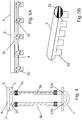
Fig. 5A zeigt eine Draufsicht auf ein befülltes Verteilrohr, wie es für die vorliegenden Erfindung verwendet werden kann; -
Fig. 5B zeigt eine perspektivische Ansicht des Verteilrohres gemäßFig. 5A ; -
Fig. 6 zeigt eine perspektivische Ansicht eines Metallgerüsts, wie es für Ausführungen von Reaktorelementen des erfindungsgemäßen Photobioreaktors werden kann; -
Fig. 7 zeigt eine perspektivische Ansicht von Reaktorelementen einer Ausführungsform des erfindungsgemäßen Photobioreaktors. -
Fig. 2 zeigt einen Photobioreaktor 1 zur Kultivierung von phototrophen Mikroorganismen, mit zwei Reaktorelementen 2, die jeweils eine Vielzahl von vertikalen, geraden Steigrohren 3a und Fallrohren 3b für Kulturmedium 4 und ein horizontales, gerades Verteilrohr 5 aufweisen. Das Kulturmedium 4 ist ein flüssiges Kulturmedium auf Wasserbasis und angereichert mit Nährstoffen; es beinhaltet die phototrophen Mikroorganismen (üblicherweise Mikroalgen). Die genannten Rohre bestehen aus Glas, wobei die Verteilrohre 5 mit Anschlussfortsätzen 50 vorgesehen sind (vgl. auchFig. 5A und Fig. 5B ). Die Steigrohre 3a und Fallrohre 3b sind jeweils an ihrem oberen Ende 6 mit Hilfe der Rohrverbinder 51 mit den Anschlussfortsätzen 50 des Verteilrohres 5 flüssigkeitsdurchlässig verbunden. Die Steigrohre 3a und die Fallrohre 3b sind zusätzlich miteinander durch je ein U-förmiges Verbindungsstück 7 flüssigkeitsdurchlässig verbunden (vgl. auchFig. 4 ). - Der Photobioreaktor 1 weist ferner eine Einrichtung 8 zum Einleiten von Kohlendioxid (und/oder Druckluft) in die Steigrohre 3a bzw. die Fallrohre 3b auf. Für das mit dem Fallrohr 3b durch das Verbindungsstück 7 verbundene Steigrohr 3a ist ein Einlass 14a zur Begasung durch die Einrichtung 8 vorgesehen. Für das mit dem Steigrohr 3a durch das Verbindungsstück 7 verbundene Fallrohr 3b ist ein weiterer Einlass 14b zur Begasung durch die Einrichtung 8 vorgesehen. Das Kohlendioxid wird durch eine Gaspumpe aus einem Flüssigtank in ein Gasverteilrohr gepumpt. Die Anschlüsse des Gasverteilrohres sind durch Schläuche mit je einem Einlass 14a bzw. 14b verbunden. Durch Vorsehen einer Öffnung des Einlasses 14a, die durchlässiger ist als die Öffnung des Einlasses 14b, wird eine stärkere Begasung der Steigrohre 3a gegenüber den Fallrohren 3b ermöglicht. Dadurch kommt es - überraschenderweise obwohl am jeweiligen oberen Ende 6 der Steigrohre 3a bzw. Fallrohre 3b keine U-förmigen Verbindungsstücke 7 sondern das Verteilrohr 5 vorgesehen ist - zu einer mäanderförmigen Strömung des Kulturmediums 4 (aufwärts in den Steigrohren 3a, abwärts in den Fallrohren 3b; vgl. auch die gestrichelten Pfeile in
Fig. 3 ). Diese mäanderförmige Strömung wird darüber hinaus weiter stabilisiert, indem die zwei Reaktorelemente 2 über ein Fallrohr 3b des ersten Reaktorelements 2 mit einem Steigrohr 3a des zweiten Reaktorelements 2 miteinander durch ein U-förmiges Verbindungsstück 7 flüssigkeitsdurchlässig verbunden sind - also vereinfacht gesagt durch Vorsehen einer "Lücke" zwischen den beiden Verteilrohren 5. - Der Einlass 52a und der Auslass 52b können durch einen Schlauch miteinander verbunden werden, wodurch ein zyklischer Betrieb des Photobioreaktors 1 ermöglicht wird. Nach einer gewissen Anzahl an Zyklen unter Belichtung kann das Kulturmedium 4, das nun eine deutlich höhere Konzentration an Mikroorganismen enthält, am Auslass 52b zur Ernte (d.h. zur Aufkonzentration und Trocknung der phototrophen Mikroorganismen) entnommen werden, während am Einlass 52a frisches Kulturmedium 4 mit einer niedrigen Anfangskonzentration an phototrophen Mikroorganismen eingebracht wird. Selbstverständlich ist auch ein kontinuierlicher zyklischer Betrieb denkbar, bei dem der Einlass 52a mit dem Auslass 52b durch einen Schlauch verbunden bleibt, und an einem Einlass in einem ersten unteren Verbindungsstück 7 kontinuierlich frisches Kulturmedium 5 zugeführt wird und an einem Auslass in einem ausgehend von der Strömungsrichtung direkt davor liegenden zweiten unteren Verbindungsstück 7 kontinuierlich dieselbe Menge dichteres Kulturmedium 4 entnommen wird. Dafür ist naturgemäß eine gewisse Mindestlänge der Zuchtstrecke erforderlich. Ebenso ist, wenn der Photobioreaktor 1 eine gewisse Mindestlänge aufweist, auch ein kontinuierlicher linearer Betrieb denkbar, bei dem kontinuierlich frisches Kulturmedium 4 mit einer niedrigen Anfangskonzentration an phototrophen Mikroorganismen beim Einlass 52a eingebracht wird und kontinuierlich dieselbe Menge reifes Kulturmedium 4 am Auslass 52b zur Ernte entnommen wird. Einlässe können jedoch auch an anderen Stellen des Reaktors vorgesehen werden (z.B. U-Bogen-Verbindungsstück des ersten/letzten Steig- bzw. Fallrohres, aber auch in einem anderen U-Bogen-Verbindungsstück im Photobioreaktor).
- Das mäanderförmig strömende Kulturmedium 4 mit den phototrophen Mikroorganismen steht in den Reaktorelementen 2 so hoch, dass auch die Verteilrohre 5 jeweils etwa zur Hälfte damit befüllt sind. Im Verteilrohr 5 sind also sowohl Kulturmedium 4 als auch, oberhalb des Kulturmediums 4, ein Gasraum 9 zur Aufnahme von aus dem Kulturmedium 4 aufsteigenden Gasblasen 10 vorhanden, wobei im Verteilrohr 5 eine Grenzfläche 11 zwischen dem Kulturmedium 4 und dem Gasraum 9 angeordnet ist. Der Gasdruckausgleich mit der Umgebung findet über das Ventil 53 statt, welches mit einem Filtersystem ausgestattet ist, um Kontamination des Kulturmediums 4 zu vermeiden.
- Die mit der Grenzfläche 11 zwischen Kulturmedium 4 und Gasraum 9 in Zusammenhang stehenden Verschmutzungen an der Innenoberfläche des Verteilrohres 5 können mit verhältnismäßig geringem Aufwand gereinigt werden, indem der Photobioreaktor 1 kurz außer Betrieb genommen wird, das Kulturmedium 4 aus dem Verteilrohr 5 abgelassen wird, die Abdeckplatte 54 des Verteilrohres entfernt wird und die Innenoberfläche das Verteilrohres z.B. mit einer an einer Teleskopstange befestigten Bürste gereinigt wird.
- Die in
Fig. 3 gezeigte Ausführung des Photobioreaktors 1 ermöglicht die Reinigung bzw. das Sauberhalten der inneren Oberfläche des Verteilrohres 5 während des Betriebes. Dabei ist am Verteilrohr 5 die Führungsschiene 12 für die bewegliche Instandhaltungsvorrichtung 13 vorgesehen. Die Instandhaltungsvorrichtung 13 ist mit Bürsten und Sprühdüsen für die inneren Oberfläche des Verteilrohres 5 ausgestattet. Die Instandhaltungsvorrichtung 13 ist z.B. magnetisch und kann durch einen in der Führungsschiene 12 verschiebbaren Magneten (oder Seile) bewegt werden. Die Instandhaltungsvorrichtung 13 ist umströmbar und kann während des laufenden Betriebes in voreinstellbaren Zeitabständen eingesetzt werden, was die Stehzeiten des Photobioreaktors 1 wesentlich verringert. Die gestrichelten Pfeile verdeutlichen den Strömungspfad im Reaktorelement 2. -
Fig. 7 zeigt schematisch eine Ausführungsform des Photobioreaktors 1, bei der das jeweilige Verteilrohr 5 eines Reaktorelements 2 aus miteinander direkt verbundenen Glasteilstücken 56 besteht. Jeweils zwei Reaktorelemente 2 werden durch das inFig. 6 gezeigte Metallgerüst 55 gehalten.
Claims (12)
- Photobioreaktor (1) zur Kultivierung phototropher Mikroorganismen,
mit einem Reaktorelement (2), das eine Vielzahl von Steig- (3a) und Fallrohren (3b) für flüssiges Kulturmedium (4), welches die Mikroorganismen beinhaltet, und ein Verteilrohr (5) aufweist, wobei die Steig- (3a) und Fallrohre (3b) jeweils an ihrem oberen Ende (6) mit dem Verteilrohr (5) flüssigkeitsdurchlässig verbunden sind, wobei zumindest eines der Steig- (3a) und eines der Fallrohre (3b) zusätzlich miteinander durch ein Verbindungsstück (7) flüssigkeitsdurchlässig verbunden sind,
wobei der Photobioreaktor (1) ferner eine Einrichtung (8) zum Einleiten von Gas in zumindest ein Steigrohr (3a) aufweist,
dadurch gekennzeichnet, dass der Photobioreaktor (1) derart ausgelegt ist, dass im Betriebszustand im Verteilrohr (5) sowohl Kulturmedium (4) als auch, oberhalb des Kulturmediums (4), ein Gasraum (9) zur Aufnahme von aus dem Kulturmedium (4) aufsteigenden Gasblasen (10) vorhanden sind, wobei im Verteilrohr (5) eine Grenzfläche (11) zwischen dem Kulturmedium (4) und dem Gasraum (9) angeordnet ist. - Photobioreaktor (1) gemäß Anspruch 1, dadurch gekennzeichnet, dass zumindest zwei Reaktorelemente (2) vorgesehen sind, wobei ein Fallrohr (3b) des ersten Reaktorelements (2) mit einem Steigrohr (3a) des zweiten Reaktorelements (2) miteinander durch ein Verbindungsstück (7) flüssigkeitsdurchlässig verbunden sind.
- Photobioreaktor (1) gemäß Anspruch 1 oder 2, dadurch gekennzeichnet, dass die Steig- (3a) und Fallrohre (3b) und/oder das Verteilrohr (5) im Wesentlichen aus Glas bestehen.
- Photobioreaktor (1) gemäß einem der Ansprüche 1 bis 3, dadurch gekennzeichnet, dass am Verteilrohr (5) eine Einrichtung (12) zur Führung einer im Verteilrohr (5) beweglichen Instandhaltungsvorrichtung (13) vorgesehen ist.
- Photobioreaktor (1) gemäß einem der Ansprüche 1 bis 4, dadurch gekennzeichnet, dass für das mit dem Fallrohr (3b) durch das Verbindungsstück (7) verbundene Steigrohr (3a) ein Einlass (14a) zur Begasung mit der Einrichtung (8) vorgesehen ist, und dass für das mit dem Steigrohr (3a) durch das Verbindungsstück (7) verbundene Fallrohr (3b) ein weiterer Einlass (14b) zur Begasung mit der Einrichtung (8) vorgesehen ist.
- Photobioreaktor (1) gemäß Anspruch 5, dadurch gekennzeichnet, dass zumindest einer der Einlässe zur Begasung (14a,14b) im Verbindungsstück (7) vorgesehen ist.
- Photobioreaktor (1) gemäß Anspruch 5 oder 6, dadurch gekennzeichnet, dass er derart ausgelegt ist, dass im Betriebszustand eine Agitation und/oder ein Fluss des Kulturmediums (4) im Wesentlichen durch die im Kulturmedium (4) aufsteigenden Gasblasen (10) verursacht wird.
- Photobioreaktor (1) gemäß Anspruch 7, dadurch gekennzeichnet, dass er derart ausgelegt ist, dass im Betriebszustand eine mäanderförmiger Strömung des Kulturmediums (4) durch die Steig-(3a) und Fallrohre (3b) dadurch erreicht wird, dass das Kulturmedium (4) im mit dem Fallrohr (3b) durch das Verbindungsstück (7) verbundenen Steigrohr (3a) stärker begast wird als in dem Fallrohr (3b).
- Verfahren zur Kultivierung phototropher Mikroorganismen, umfassend das Belichten eines Photobioreaktors (1),
wobei der Photobioreaktor (1) versehen ist mit einem Reaktorelement (2), das eine Vielzahl von Steig- (3a) und Fallrohren (3b) für flüssiges Kulturmedium (4), welches die Mikroorganismen beinhaltet, und ein Verteilrohr (5) aufweist, wobei die Steig-(3a) und Fallrohre (3b) jeweils an ihrem oberen Ende (6) mit dem Verteilrohr (5) flüssigkeitsdurchlässig verbunden sind, wobei zumindest eines der Steig- (3a) und eines der Fallrohre (3b) zusätzlich miteinander durch ein Verbindungsstück (7) flüssigkeitsdurchlässig verbunden sind,
und wobei der Photobioreaktor (1) in den Steig- (3a) und Fallrohren (3b) flüssiges Kulturmedium (4) mit den Mikroorganismen beinhaltet, welches zumindest teilweise begast wird,
dadurch gekennzeichnet, dass im Verteilrohr (5) sowohl flüssiges Kulturmedium (4) mit den Mikroorganismen als auch, oberhalb des Kulturmediums (4), ein Gasraum (9) vorhanden sind, wobei im Verteilrohr (5) eine Grenzfläche (11) zwischen dem Kulturmedium (4) und dem Gasraum (9) ausgebildet wird, und der Gasraum (9) aus dem Kulturmedium (4) aufsteigende Gasblasen (10) aufnimmt. - Verfahren gemäß Anspruch 9, dadurch gekennzeichnet, dass der Photobioreaktor der Photobioreaktor gemäß einem der Ansprüche 1 bis 8 ist.
- Verfahren gemäß Anspruch 9 oder 10, dadurch gekennzeichnet, dass das Kulturmedium (4) mäanderförmig durch die Steig- (3a) und Fallrohre (3b) strömt.
- Verfahren gemäß einem der Ansprüche 8 bis 11, dadurch gekennzeichnet, dass die innere Oberfläche des Verteilrohres (5) von der beweglichen Instandhaltungsvorrichtung (13), vorzugsweise in voreinstellbaren Zeitabständen, gereinigt wird.
Priority Applications (4)
| Application Number | Priority Date | Filing Date | Title |
|---|---|---|---|
| RS20211298A RS62469B1 (sr) | 2016-08-30 | 2017-08-30 | Fotobioreaktor i postupak za gajenje mikroalgi |
| HRP20211635TT HRP20211635T1 (hr) | 2016-08-30 | 2017-08-30 | Fotobioreaktor i postupak za kultiviranje mikroalgi |
| PL17762082T PL3507355T3 (pl) | 2016-08-30 | 2017-08-30 | Fotobioreaktor i sposób hodowli mikroalg |
| SI201730947T SI3507355T1 (sl) | 2016-08-30 | 2017-08-30 | Fotobioreaktor in postopek za gojenje mikroalg |
Applications Claiming Priority (2)
| Application Number | Priority Date | Filing Date | Title |
|---|---|---|---|
| EP16186440.0A EP3290505A1 (de) | 2016-08-30 | 2016-08-30 | Photobioreaktor und verfahren zur kultivierung von mikroalgen |
| PCT/EP2017/071707 WO2018041863A1 (de) | 2016-08-30 | 2017-08-30 | Photobioreaktor und verfahren zur kultivierung von mikroalgen |
Publications (2)
| Publication Number | Publication Date |
|---|---|
| EP3507355A1 EP3507355A1 (de) | 2019-07-10 |
| EP3507355B1 true EP3507355B1 (de) | 2021-07-21 |
Family
ID=56851488
Family Applications (4)
| Application Number | Title | Priority Date | Filing Date |
|---|---|---|---|
| EP16186440.0A Withdrawn EP3290505A1 (de) | 2016-08-30 | 2016-08-30 | Photobioreaktor und verfahren zur kultivierung von mikroalgen |
| EP17155258.1A Withdrawn EP3290506A1 (de) | 2016-08-30 | 2017-02-08 | Photobioreaktor mit beweglicher instandhaltungsvorrichtung |
| EP17762082.0A Active EP3507355B1 (de) | 2016-08-30 | 2017-08-30 | Photobioreaktor und verfahren zur kultivierung von mikroalgen |
| EP17765365.6A Active EP3507357B1 (de) | 2016-08-30 | 2017-08-30 | Photobioreaktor mit beweglicher instandhaltungsvorrichtung |
Family Applications Before (2)
| Application Number | Title | Priority Date | Filing Date |
|---|---|---|---|
| EP16186440.0A Withdrawn EP3290505A1 (de) | 2016-08-30 | 2016-08-30 | Photobioreaktor und verfahren zur kultivierung von mikroalgen |
| EP17155258.1A Withdrawn EP3290506A1 (de) | 2016-08-30 | 2017-02-08 | Photobioreaktor mit beweglicher instandhaltungsvorrichtung |
Family Applications After (1)
| Application Number | Title | Priority Date | Filing Date |
|---|---|---|---|
| EP17765365.6A Active EP3507357B1 (de) | 2016-08-30 | 2017-08-30 | Photobioreaktor mit beweglicher instandhaltungsvorrichtung |
Country Status (16)
| Country | Link |
|---|---|
| US (2) | US11976260B2 (de) |
| EP (4) | EP3290505A1 (de) |
| AU (1) | AU2017317622B2 (de) |
| CY (1) | CY1124722T1 (de) |
| DK (1) | DK3507355T3 (de) |
| ES (2) | ES2894892T3 (de) |
| HR (2) | HRP20231727T1 (de) |
| HU (2) | HUE064264T2 (de) |
| IL (1) | IL265006B (de) |
| LT (1) | LT3507355T (de) |
| PL (2) | PL3507355T3 (de) |
| PT (1) | PT3507355T (de) |
| RS (2) | RS65046B1 (de) |
| SI (1) | SI3507355T1 (de) |
| SM (1) | SMT202300419T1 (de) |
| WO (2) | WO2018041863A1 (de) |
Families Citing this family (4)
| Publication number | Priority date | Publication date | Assignee | Title |
|---|---|---|---|---|
| EP3290505A1 (de) * | 2016-08-30 | 2018-03-07 | ecoduna AG | Photobioreaktor und verfahren zur kultivierung von mikroalgen |
| CN109401920A (zh) * | 2018-12-12 | 2019-03-01 | 河西学院 | 一种可控坡式微藻养殖系统及其微藻养殖的方法 |
| JP7102597B1 (ja) | 2021-11-04 | 2022-07-19 | 三菱化工機株式会社 | 微細藻類培養装置 |
| JP2025535790A (ja) * | 2022-10-16 | 2025-10-28 | ソーラークリーン フューエルズ, エルエルシー | 垂直バイオリアクタ技術の方法、システム、およびプロセス |
Family Cites Families (18)
| Publication number | Priority date | Publication date | Assignee | Title |
|---|---|---|---|---|
| US5001066A (en) * | 1982-01-18 | 1991-03-19 | Phillips Petroleum Company | Method for carrying out sparged reaction |
| FR2696753B1 (fr) | 1992-10-13 | 1995-01-20 | Inst Fs Rech Expl Mer | Dispositif de nettoyage des canalisations d'un photobioréacteur et photobioréacteur muni de ce dispositif. |
| DE102004043435A1 (de) * | 2004-09-06 | 2006-03-09 | Infors Ag | Reaktor |
| WO2009051478A2 (en) * | 2007-10-15 | 2009-04-23 | Algaelink N.V. | Photobioreactor with a cleaning system and method for cleaning such a reactor |
| WO2009094680A1 (de) * | 2008-01-31 | 2009-08-06 | Martin Mohr | Verfahren und einrichtung für einen photochemischen prozess |
| US8183032B2 (en) * | 2008-08-28 | 2012-05-22 | Innovative American Technology Inc. | Semi-closed loop alga-diesel fuel photobioreactor using waste water |
| FR2943685B1 (fr) * | 2009-03-25 | 2011-04-29 | Microphyt | Reacteur photosynthetique pour la culture de microorganiques et procede de culture de microorganismes |
| DE102009029792A1 (de) | 2009-06-18 | 2010-12-30 | Schott Ag | Beschichtung für Behälter wasserführender Systeme |
| US20110027875A1 (en) | 2009-07-14 | 2011-02-03 | Paul Cathcart | Inexpensive, Vertical, Production Photobioteactor |
| DE102009028339A1 (de) | 2009-08-07 | 2011-02-24 | Wacker Chemie Ag | Bioreaktor aus Siliconmaterialien |
| CN202968549U (zh) * | 2012-12-17 | 2013-06-05 | 甘肃凯源生物技术开发中心 | 同步分离清洗一体采收机 |
| JP6461015B2 (ja) | 2013-02-26 | 2019-01-30 | ヒリエ デベロップメント, エルエルシー | モジュール式管状バイオリアクタ |
| US9347030B2 (en) | 2013-02-28 | 2016-05-24 | Julian Fiorentino | Photobioreactor |
| SG11201607873VA (en) * | 2013-12-31 | 2016-11-29 | Algae Enviro Engineering Pte Ltd | System for mass cultivation of microorganisms and products therefrom |
| EP2947139B1 (de) * | 2014-04-25 | 2016-09-07 | Infors AG | Reaktor, Reinigungsverfahren für diesen sowie Verwendung |
| AT515854B1 (de) * | 2014-05-30 | 2018-07-15 | Ecoduna Ag | Verfahren für einen photochemischen, wie photokatalytischen und/oder photosynthetischen Prozess |
| AT517188A1 (de) | 2015-04-24 | 2016-11-15 | Ecoduna Ag | Verfahren zur Gewinnung, insbesondere zum Ernten, von Algen und Mikroorganismen |
| EP3290505A1 (de) * | 2016-08-30 | 2018-03-07 | ecoduna AG | Photobioreaktor und verfahren zur kultivierung von mikroalgen |
-
2016
- 2016-08-30 EP EP16186440.0A patent/EP3290505A1/de not_active Withdrawn
-
2017
- 2017-02-08 EP EP17155258.1A patent/EP3290506A1/de not_active Withdrawn
- 2017-08-30 HU HUE17765365A patent/HUE064264T2/hu unknown
- 2017-08-30 IL IL265006A patent/IL265006B/en unknown
- 2017-08-30 HU HUE17762082A patent/HUE056331T2/hu unknown
- 2017-08-30 ES ES17762082T patent/ES2894892T3/es active Active
- 2017-08-30 ES ES17765365T patent/ES2964941T3/es active Active
- 2017-08-30 SI SI201730947T patent/SI3507355T1/sl unknown
- 2017-08-30 PL PL17762082T patent/PL3507355T3/pl unknown
- 2017-08-30 EP EP17762082.0A patent/EP3507355B1/de active Active
- 2017-08-30 US US16/329,045 patent/US11976260B2/en active Active
- 2017-08-30 WO PCT/EP2017/071707 patent/WO2018041863A1/de not_active Ceased
- 2017-08-30 LT LTEPPCT/EP2017/071707T patent/LT3507355T/lt unknown
- 2017-08-30 AU AU2017317622A patent/AU2017317622B2/en not_active Ceased
- 2017-08-30 DK DK17762082.0T patent/DK3507355T3/da active
- 2017-08-30 US US16/329,053 patent/US11098276B2/en not_active Expired - Fee Related
- 2017-08-30 RS RS20231272A patent/RS65046B1/sr unknown
- 2017-08-30 HR HRP20231727TT patent/HRP20231727T1/hr unknown
- 2017-08-30 WO PCT/EP2017/071702 patent/WO2018041859A1/de not_active Ceased
- 2017-08-30 HR HRP20211635TT patent/HRP20211635T1/hr unknown
- 2017-08-30 SM SM20230419T patent/SMT202300419T1/it unknown
- 2017-08-30 PL PL17765365.6T patent/PL3507357T3/pl unknown
- 2017-08-30 EP EP17765365.6A patent/EP3507357B1/de active Active
- 2017-08-30 RS RS20211298A patent/RS62469B1/sr unknown
- 2017-08-30 PT PT177620820T patent/PT3507355T/pt unknown
-
2021
- 2021-10-20 CY CY20211100918T patent/CY1124722T1/el unknown
Non-Patent Citations (1)
| Title |
|---|
| None * |
Also Published As
| Publication number | Publication date |
|---|---|
| EP3507357B1 (de) | 2023-10-11 |
| HUE064264T2 (hu) | 2024-02-28 |
| US20190218490A1 (en) | 2019-07-18 |
| US20190218491A1 (en) | 2019-07-18 |
| EP3290506A1 (de) | 2018-03-07 |
| DK3507355T3 (da) | 2021-10-25 |
| RS65046B1 (sr) | 2024-02-29 |
| HRP20231727T1 (hr) | 2024-03-15 |
| PT3507355T (pt) | 2021-10-21 |
| SMT202300419T1 (it) | 2024-01-10 |
| EP3507355A1 (de) | 2019-07-10 |
| WO2018041863A1 (de) | 2018-03-08 |
| AU2017317622A1 (en) | 2019-03-21 |
| SI3507355T1 (sl) | 2022-01-31 |
| EP3507357C0 (de) | 2023-10-11 |
| CY1124722T1 (el) | 2022-07-22 |
| AU2017317622B2 (en) | 2022-02-17 |
| HRP20211635T1 (hr) | 2022-02-04 |
| LT3507355T (lt) | 2021-11-10 |
| EP3290505A1 (de) | 2018-03-07 |
| PL3507357T3 (pl) | 2024-03-11 |
| IL265006B (en) | 2022-09-01 |
| ES2964941T3 (es) | 2024-04-10 |
| PL3507355T3 (pl) | 2022-01-24 |
| ES2894892T3 (es) | 2022-02-16 |
| HUE056331T2 (hu) | 2022-02-28 |
| RS62469B1 (sr) | 2021-11-30 |
| WO2018041859A1 (de) | 2018-03-08 |
| EP3507357A1 (de) | 2019-07-10 |
| US11098276B2 (en) | 2021-08-24 |
| IL265006A (de) | 2019-04-30 |
| US11976260B2 (en) | 2024-05-07 |
Similar Documents
| Publication | Publication Date | Title |
|---|---|---|
| DE60110765T2 (de) | Verfahren und behälter für hydroponische und aeroponische kultur | |
| EP2446016B1 (de) | Verfahren zur biomasseproduktion und photobioreaktor zur kultivierung phototropher oder mixotropher organismen oder zellen | |
| WO2018041863A1 (de) | Photobioreaktor und verfahren zur kultivierung von mikroalgen | |
| DE102019118034B3 (de) | Landbasierte Aquakulturanlage zur Produktion von Wassertieren und Anwendung der Anlage | |
| DE202008013223U1 (de) | Indoor-Fischfarm mit aufgeständertem Becken | |
| DE2035085A1 (de) | Vorrichtung und Verfahren zur bio logischen Behandlung von Abwassern und sonstigen Abfallprodukten | |
| WO1987007475A1 (en) | Fish basin for intensive fish-fattening and process for operating such a fish basin | |
| CH713212A2 (de) | Verfahren und Einrichtung zum Reinigen und Desinfizieren von Gegenständen, insbesondere von medizinischen invasiven Instrumenten mittels Multifrequenz-Ultraschalltechnik. | |
| DE102009021059A1 (de) | Anlage für die Mikroalgenproduktion | |
| WO2021089085A9 (de) | Verfahren und einrichtung zur produktion von mikroalgenbiomasse | |
| DE202005001733U1 (de) | Solar-Reaktor für pflanzliche Algen und Mikroorganismen | |
| EP0085688B1 (de) | Verfahren und anlage zum durchführen von fotochemischen prozessen | |
| DE2605787A1 (de) | Einrichtung zur wasseraufbereitung und aufrechterhaltung eines wasserkreislaufs, insbesondere zur aufzucht von fischen | |
| DE102007012745A1 (de) | Verfahren und System der photosynthetischen Reaktion von Algen und Mikroben | |
| DE60106257T2 (de) | Trinkanlage zum Versorgen von Geflügel mit Trinkflüssigkeit | |
| AT251342B (de) | Anlage zur künstlichen Züchtung von Pflanzen, Bakterien u. ähnl. Lebewesen | |
| DE102019114979A1 (de) | Photobioreaktor, insbesondere zur Produktion von Mikroorganismen wie beispielsweise Mikroalgen | |
| CH707832B1 (de) | Aquakultur zur Aufzucht von Fischen. | |
| CN112295721A (zh) | 一种生态鲫鱼养殖用蛆虫分离装置 | |
| DE2300786C3 (de) | Tank, für die Bierherstellung | |
| DE102019121741B4 (de) | Vorrichtung zur Versorgung von Insekten | |
| DE202006020530U1 (de) | Kulturvorrichtung für aquatische Organismen | |
| EP1102721A2 (de) | Verfahren und vorrichtung zur trennung von biomasse und wasser | |
| DE2640114A1 (de) | Anlage fuer die zucht von pflanzen in mit einer fluessigkeit berieselten behaeltern | |
| WO2012097981A1 (de) | Algenernteverfahren und algenerntevorrichtung zur durchführung des algenernteverfahrens |
Legal Events
| Date | Code | Title | Description |
|---|---|---|---|
| REG | Reference to a national code |
Ref country code: HR Ref legal event code: TUEP Ref document number: P20211635T Country of ref document: HR |
|
| STAA | Information on the status of an ep patent application or granted ep patent |
Free format text: STATUS: UNKNOWN |
|
| STAA | Information on the status of an ep patent application or granted ep patent |
Free format text: STATUS: THE INTERNATIONAL PUBLICATION HAS BEEN MADE |
|
| PUAI | Public reference made under article 153(3) epc to a published international application that has entered the european phase |
Free format text: ORIGINAL CODE: 0009012 |
|
| STAA | Information on the status of an ep patent application or granted ep patent |
Free format text: STATUS: REQUEST FOR EXAMINATION WAS MADE |
|
| 17P | Request for examination filed |
Effective date: 20190315 |
|
| AK | Designated contracting states |
Kind code of ref document: A1 Designated state(s): AL AT BE BG CH CY CZ DE DK EE ES FI FR GB GR HR HU IE IS IT LI LT LU LV MC MK MT NL NO PL PT RO RS SE SI SK SM TR |
|
| AX | Request for extension of the european patent |
Extension state: BA ME |
|
| DAV | Request for validation of the european patent (deleted) | ||
| DAX | Request for extension of the european patent (deleted) | ||
| GRAP | Despatch of communication of intention to grant a patent |
Free format text: ORIGINAL CODE: EPIDOSNIGR1 |
|
| STAA | Information on the status of an ep patent application or granted ep patent |
Free format text: STATUS: GRANT OF PATENT IS INTENDED |
|
| INTG | Intention to grant announced |
Effective date: 20200401 |
|
| GRAS | Grant fee paid |
Free format text: ORIGINAL CODE: EPIDOSNIGR3 |
|
| 19U | Interruption of proceedings before grant |
Effective date: 20200822 |
|
| 19W | Proceedings resumed before grant after interruption of proceedings |
Effective date: 20210601 |
|
| GRAA | (expected) grant |
Free format text: ORIGINAL CODE: 0009210 |
|
| STAA | Information on the status of an ep patent application or granted ep patent |
Free format text: STATUS: THE PATENT HAS BEEN GRANTED |
|
| RAP3 | Party data changed (applicant data changed or rights of an application transferred) |
Owner name: BECO INVEST B.V. |
|
| AK | Designated contracting states |
Kind code of ref document: B1 Designated state(s): AL AT BE BG CH CY CZ DE DK EE ES FI FR GB GR HR HU IE IS IT LI LT LU LV MC MK MT NL NO PL PT RO RS SE SI SK SM TR |
|
| REG | Reference to a national code |
Ref country code: GB Ref legal event code: FG4D Free format text: NOT ENGLISH |
|
| REG | Reference to a national code |
Ref country code: CH Ref legal event code: EP |
|
| REG | Reference to a national code |
Ref country code: DE Ref legal event code: R096 Ref document number: 502017010975 Country of ref document: DE |
|
| REG | Reference to a national code |
Ref country code: AT Ref legal event code: REF Ref document number: 1412641 Country of ref document: AT Kind code of ref document: T Effective date: 20210815 |
|
| REG | Reference to a national code |
Ref country code: IE Ref legal event code: FG4D Free format text: LANGUAGE OF EP DOCUMENT: GERMAN |
|
| REG | Reference to a national code |
Ref country code: FI Ref legal event code: FGE Ref country code: PT Ref legal event code: SC4A Ref document number: 3507355 Country of ref document: PT Date of ref document: 20211021 Kind code of ref document: T Free format text: AVAILABILITY OF NATIONAL TRANSLATION Effective date: 20211014 |
|
| REG | Reference to a national code |
Ref country code: DK Ref legal event code: T3 Effective date: 20211021 |
|
| REG | Reference to a national code |
Ref country code: SE Ref legal event code: TRGR |
|
| REG | Reference to a national code |
Ref country code: RO Ref legal event code: EPE |
|
| REG | Reference to a national code |
Ref country code: NL Ref legal event code: FP |
|
| REG | Reference to a national code |
Ref country code: GR Ref legal event code: EP Ref document number: 20210402797 Country of ref document: GR Effective date: 20211209 |
|
| REG | Reference to a national code |
Ref country code: EE Ref legal event code: FG4A Ref document number: E021554 Country of ref document: EE Effective date: 20211018 |
|
| REG | Reference to a national code |
Ref country code: SK Ref legal event code: T3 Ref document number: E 38381 Country of ref document: SK |
|
| REG | Reference to a national code |
Ref country code: NO Ref legal event code: T2 Effective date: 20210721 |
|
| REG | Reference to a national code |
Ref country code: HR Ref legal event code: ODRP Ref document number: P20211635T Country of ref document: HR Payment date: 20211025 Year of fee payment: 5 |
|
| REG | Reference to a national code |
Ref country code: HR Ref legal event code: T1PR Ref document number: P20211635 Country of ref document: HR |
|
| REG | Reference to a national code |
Ref country code: ES Ref legal event code: FG2A Ref document number: 2894892 Country of ref document: ES Kind code of ref document: T3 Effective date: 20220216 |
|
| REG | Reference to a national code |
Ref country code: HU Ref legal event code: AG4A Ref document number: E056331 Country of ref document: HU |
|
| REG | Reference to a national code |
Ref country code: DE Ref legal event code: R097 Ref document number: 502017010975 Country of ref document: DE |
|
| PLBE | No opposition filed within time limit |
Free format text: ORIGINAL CODE: 0009261 |
|
| STAA | Information on the status of an ep patent application or granted ep patent |
Free format text: STATUS: NO OPPOSITION FILED WITHIN TIME LIMIT |
|
| PG25 | Lapsed in a contracting state [announced via postgrant information from national office to epo] |
Ref country code: SM Free format text: LAPSE BECAUSE OF FAILURE TO SUBMIT A TRANSLATION OF THE DESCRIPTION OR TO PAY THE FEE WITHIN THE PRESCRIBED TIME-LIMIT Effective date: 20210721 Ref country code: MC Free format text: LAPSE BECAUSE OF FAILURE TO SUBMIT A TRANSLATION OF THE DESCRIPTION OR TO PAY THE FEE WITHIN THE PRESCRIBED TIME-LIMIT Effective date: 20210721 |
|
| 26N | No opposition filed |
Effective date: 20220422 |
|
| REG | Reference to a national code |
Ref country code: HR Ref legal event code: ODRP Ref document number: P20211635 Country of ref document: HR Payment date: 20220824 Year of fee payment: 6 |
|
| REG | Reference to a national code |
Ref country code: HR Ref legal event code: ODRP Ref document number: P20211635 Country of ref document: HR Payment date: 20230818 Year of fee payment: 7 |
|
| PGFP | Annual fee paid to national office [announced via postgrant information from national office to epo] |
Ref country code: NL Payment date: 20230821 Year of fee payment: 7 Ref country code: LU Payment date: 20230821 Year of fee payment: 7 |
|
| PGFP | Annual fee paid to national office [announced via postgrant information from national office to epo] |
Ref country code: TR Payment date: 20230825 Year of fee payment: 7 Ref country code: RO Payment date: 20230822 Year of fee payment: 7 Ref country code: NO Payment date: 20230824 Year of fee payment: 7 Ref country code: IT Payment date: 20230825 Year of fee payment: 7 Ref country code: IE Payment date: 20230822 Year of fee payment: 7 Ref country code: GB Payment date: 20230822 Year of fee payment: 7 Ref country code: FI Payment date: 20230821 Year of fee payment: 7 Ref country code: EE Payment date: 20230814 Year of fee payment: 7 Ref country code: CZ Payment date: 20230821 Year of fee payment: 7 Ref country code: CY Payment date: 20230822 Year of fee payment: 7 Ref country code: CH Payment date: 20230902 Year of fee payment: 7 Ref country code: BG Payment date: 20230823 Year of fee payment: 7 Ref country code: AT Payment date: 20230822 Year of fee payment: 7 |
|
| PGFP | Annual fee paid to national office [announced via postgrant information from national office to epo] |
Ref country code: SK Payment date: 20230821 Year of fee payment: 7 Ref country code: SI Payment date: 20230817 Year of fee payment: 7 Ref country code: SE Payment date: 20230821 Year of fee payment: 7 Ref country code: RS Payment date: 20230817 Year of fee payment: 7 Ref country code: PT Payment date: 20230817 Year of fee payment: 7 Ref country code: PL Payment date: 20230817 Year of fee payment: 7 Ref country code: IS Payment date: 20230810 Year of fee payment: 7 Ref country code: HU Payment date: 20230823 Year of fee payment: 7 Ref country code: HR Payment date: 20230818 Year of fee payment: 7 Ref country code: GR Payment date: 20230822 Year of fee payment: 7 Ref country code: FR Payment date: 20230828 Year of fee payment: 7 Ref country code: DK Payment date: 20230823 Year of fee payment: 7 Ref country code: DE Payment date: 20230821 Year of fee payment: 7 Ref country code: BE Payment date: 20230821 Year of fee payment: 7 |
|
| PGFP | Annual fee paid to national office [announced via postgrant information from national office to epo] |
Ref country code: MT Payment date: 20230721 Year of fee payment: 7 Ref country code: LV Payment date: 20230816 Year of fee payment: 7 Ref country code: LT Payment date: 20230721 Year of fee payment: 7 |
|
| PGFP | Annual fee paid to national office [announced via postgrant information from national office to epo] |
Ref country code: ES Payment date: 20231027 Year of fee payment: 7 |
|
| PGFP | Annual fee paid to national office [announced via postgrant information from national office to epo] |
Ref country code: AL Payment date: 20230822 Year of fee payment: 7 |
|
| PGFP | Annual fee paid to national office [announced via postgrant information from national office to epo] |
Ref country code: MK Payment date: 20230721 Year of fee payment: 7 |
|
| REG | Reference to a national code |
Ref country code: DE Ref legal event code: R119 Ref document number: 502017010975 Country of ref document: DE |
|
| REG | Reference to a national code |
Ref country code: HR Ref legal event code: PBON Ref document number: P20211635 Country of ref document: HR Effective date: 20240830 |
|
| REG | Reference to a national code |
Ref country code: DK Ref legal event code: EBP Effective date: 20240831 Ref country code: EE Ref legal event code: MM4A Ref document number: E021554 Country of ref document: EE Effective date: 20240831 |
|
| REG | Reference to a national code |
Ref country code: LT Ref legal event code: MM4D Effective date: 20240830 |
|
| REG | Reference to a national code |
Ref country code: CH Ref legal event code: PL |
|
| REG | Reference to a national code |
Ref country code: SE Ref legal event code: EUG |
|
| REG | Reference to a national code |
Ref country code: NL Ref legal event code: MM Effective date: 20240901 |
|
| PG25 | Lapsed in a contracting state [announced via postgrant information from national office to epo] |
Ref country code: PT Free format text: LAPSE BECAUSE OF NON-PAYMENT OF DUE FEES Effective date: 20250228 Ref country code: HR Free format text: LAPSE BECAUSE OF NON-PAYMENT OF DUE FEES Effective date: 20240830 |
|
| PG25 | Lapsed in a contracting state [announced via postgrant information from national office to epo] |
Ref country code: LT Free format text: LAPSE BECAUSE OF NON-PAYMENT OF DUE FEES Effective date: 20240830 Ref country code: FI Free format text: LAPSE BECAUSE OF NON-PAYMENT OF DUE FEES Effective date: 20240830 Ref country code: RO Free format text: LAPSE BECAUSE OF NON-PAYMENT OF DUE FEES Effective date: 20240830 |
|
| REG | Reference to a national code |
Ref country code: AT Ref legal event code: MM01 Ref document number: 1412641 Country of ref document: AT Kind code of ref document: T Effective date: 20240830 |
|
| PG25 | Lapsed in a contracting state [announced via postgrant information from national office to epo] |
Ref country code: LU Free format text: LAPSE BECAUSE OF NON-PAYMENT OF DUE FEES Effective date: 20240830 Ref country code: BG Free format text: LAPSE BECAUSE OF NON-PAYMENT OF DUE FEES Effective date: 20240830 |
|
| PG25 | Lapsed in a contracting state [announced via postgrant information from national office to epo] |
Ref country code: HU Free format text: LAPSE BECAUSE OF NON-PAYMENT OF DUE FEES Effective date: 20240831 |
|
| GBPC | Gb: european patent ceased through non-payment of renewal fee |
Effective date: 20240830 |
|
| PG25 | Lapsed in a contracting state [announced via postgrant information from national office to epo] |
Ref country code: NO Free format text: LAPSE BECAUSE OF NON-PAYMENT OF DUE FEES Effective date: 20240831 |
|
| REG | Reference to a national code |
Ref country code: SK Ref legal event code: MM4A Ref document number: E 38381 Country of ref document: SK Effective date: 20240830 |
|
| PG25 | Lapsed in a contracting state [announced via postgrant information from national office to epo] |
Ref country code: LV Free format text: LAPSE BECAUSE OF NON-PAYMENT OF DUE FEES Effective date: 20240830 Ref country code: CH Free format text: LAPSE BECAUSE OF NON-PAYMENT OF DUE FEES Effective date: 20240831 Ref country code: AT Free format text: LAPSE BECAUSE OF NON-PAYMENT OF DUE FEES Effective date: 20240830 Ref country code: GR Free format text: LAPSE BECAUSE OF NON-PAYMENT OF DUE FEES Effective date: 20250306 Ref country code: EE Free format text: LAPSE BECAUSE OF NON-PAYMENT OF DUE FEES Effective date: 20240831 |
|
| PG25 | Lapsed in a contracting state [announced via postgrant information from national office to epo] |
Ref country code: CZ Free format text: LAPSE BECAUSE OF NON-PAYMENT OF DUE FEES Effective date: 20240830 |
|
| PG25 | Lapsed in a contracting state [announced via postgrant information from national office to epo] |
Ref country code: SK Free format text: LAPSE BECAUSE OF NON-PAYMENT OF DUE FEES Effective date: 20240830 Ref country code: CY Free format text: LAPSE BECAUSE OF NON-PAYMENT OF DUE FEES Effective date: 20240830 |
|
| PG25 | Lapsed in a contracting state [announced via postgrant information from national office to epo] |
Ref country code: RS Free format text: LAPSE BECAUSE OF NON-PAYMENT OF DUE FEES Effective date: 20240830 |
|
| PG25 | Lapsed in a contracting state [announced via postgrant information from national office to epo] |
Ref country code: NL Free format text: LAPSE BECAUSE OF NON-PAYMENT OF DUE FEES Effective date: 20240901 |
|
| REG | Reference to a national code |
Ref country code: BE Ref legal event code: MM Effective date: 20240831 |
|
| PG25 | Lapsed in a contracting state [announced via postgrant information from national office to epo] |
Ref country code: DE Free format text: LAPSE BECAUSE OF NON-PAYMENT OF DUE FEES Effective date: 20250301 |
|
| PG25 | Lapsed in a contracting state [announced via postgrant information from national office to epo] |
Ref country code: DK Free format text: LAPSE BECAUSE OF NON-PAYMENT OF DUE FEES Effective date: 20240831 Ref country code: GB Free format text: LAPSE BECAUSE OF NON-PAYMENT OF DUE FEES Effective date: 20240830 |
|
| PG25 | Lapsed in a contracting state [announced via postgrant information from national office to epo] |
Ref country code: BE Free format text: LAPSE BECAUSE OF NON-PAYMENT OF DUE FEES Effective date: 20240831 Ref country code: IT Free format text: LAPSE BECAUSE OF NON-PAYMENT OF DUE FEES Effective date: 20240830 |
|
| PG25 | Lapsed in a contracting state [announced via postgrant information from national office to epo] |
Ref country code: FR Free format text: LAPSE BECAUSE OF NON-PAYMENT OF DUE FEES Effective date: 20240831 |
|
| PG25 | Lapsed in a contracting state [announced via postgrant information from national office to epo] |
Ref country code: IE Free format text: LAPSE BECAUSE OF NON-PAYMENT OF DUE FEES Effective date: 20240830 |
|
| REG | Reference to a national code |
Ref country code: SI Ref legal event code: KO00 Effective date: 20240831 |
|
| REG | Reference to a national code |
Ref country code: ES Ref legal event code: FD2A Effective date: 20251003 |
|
| PG25 | Lapsed in a contracting state [announced via postgrant information from national office to epo] |
Ref country code: ES Free format text: LAPSE BECAUSE OF NON-PAYMENT OF DUE FEES Effective date: 20240831 |
|
| PG25 | Lapsed in a contracting state [announced via postgrant information from national office to epo] |
Ref country code: SE Free format text: LAPSE BECAUSE OF NON-PAYMENT OF DUE FEES Effective date: 20240831 |
|
| PG25 | Lapsed in a contracting state [announced via postgrant information from national office to epo] |
Ref country code: PL Free format text: LAPSE BECAUSE OF NON-PAYMENT OF DUE FEES Effective date: 20240830 |