EP3502602B1 - Kühl- und/oder gefriergerät - Google Patents
Kühl- und/oder gefriergerät Download PDFInfo
- Publication number
- EP3502602B1 EP3502602B1 EP18211250.8A EP18211250A EP3502602B1 EP 3502602 B1 EP3502602 B1 EP 3502602B1 EP 18211250 A EP18211250 A EP 18211250A EP 3502602 B1 EP3502602 B1 EP 3502602B1
- Authority
- EP
- European Patent Office
- Prior art keywords
- profile
- arrangement
- web
- approximately
- freezer
- Prior art date
- Legal status (The legal status is an assumption and is not a legal conclusion. Google has not performed a legal analysis and makes no representation as to the accuracy of the status listed.)
- Active
Links
Images


Classifications
-
- F—MECHANICAL ENGINEERING; LIGHTING; HEATING; WEAPONS; BLASTING
- F25—REFRIGERATION OR COOLING; COMBINED HEATING AND REFRIGERATION SYSTEMS; HEAT PUMP SYSTEMS; MANUFACTURE OR STORAGE OF ICE; LIQUEFACTION SOLIDIFICATION OF GASES
- F25D—REFRIGERATORS; COLD ROOMS; ICE-BOXES; COOLING OR FREEZING APPARATUS NOT OTHERWISE PROVIDED FOR
- F25D23/00—General constructional features
- F25D23/08—Parts formed wholly or mainly of plastics materials
- F25D23/082—Strips
- F25D23/087—Sealing strips
Definitions
- the invention relates to the technical field of refrigerators and/or freezers, comprising at least one body and at least one closure element closing an opening of the body, as well as at least one profile arrangement according to the features arranged in a gap formed between the closure element and the body the preamble of claim 1.
- a profile arrangement is designed as a sealing arrangement for the door of a refrigerator or freezer, with a heat-insulating housing, the opening of which can be closed with a door, the side facing the opening and equipped with an inner lining has a bellows-like arrangement arranged all around the edge of the door
- a magnetic seal which is equipped with a sealing head and a sealing foot, which are connected to one another with flexible walls designed as expansion folds, the sealing foot being anchored on the interior paneling in a receiving groove which tapers on the opening side and is directed towards the door opening, while the sealing head equipped with magnetic strips
- the sealing head When the door is closed, it rests on the opening edge of the housing and holds the door on the opening edge, the sealing head being arranged laterally offset from the sealing foot, which is equipped with a one-sided bulge, which interacts with an undercut in the receiving groove and which is opposite for lateral offset is arranged closer to the seal head, the side of the seal foot opposite
- a profile arrangement is designed as an improved sealing arrangement for refrigerators and the like with a profile made of plastic material, the arrangement consisting of a cabinet, a door and an inner door panel element which can be coupled to the cabinet and a section of a bellows seal which provides a sealed closure between the door and the cabinet, providing that a profile and the sealing portion are fitted together or form a single integral part made by co-extrusion of two materials having different degrees of strength, so as to provide a convenient, if necessary to allow detachment of the sealing portion from the profile along the region of their connection, the profile having a groove adapted to receive a replacement portion of a bellows seal and at least one resilient side portion which acts to provide a snap connection between the profile and the inner door panel element , wherein the section terminates with a grooved receptacle having a substantially C-shaped cross-section and configured to receive an edge of the inner door panel member, the profile further being envisioned
- the sealing portion is further configured to define an expandable chamber acting as a bellows and having an upper chamber configured to receive a rod of magnetic material.
- a gap is formed between the upper chamber or the expandable chamber and that of the sealing arrangement.
- the disadvantage of the prior art is that, on the one hand, the optics facing the viewer in the gap between the door and the body of the refrigerator and/or freezer due to this sealing arrangement do not appear visually appealing when the refrigerator and/or freezer is closed and, on the other hand, the heat input in or the cold output from the refrigerator and/or freezer cannot be effectively prevented.
- the WO 2017/108189 A1 discloses a further generic refrigerator and/or freezer device, comprising at least one body and at least one closure element closing an opening of the body, as well as at least one profile arrangement comprising a base, at least one, arranged in a gap formed between the closure element and the body Fastening arrangement, at least one sealing arrangement and at least one profile element, with at least one free end of the profile element being arranged on the sealing arrangement, with at least one further free end of the profile element via at least one movement arrangement, with the base via at least one, at least partially protruding into the sealing arrangement , which has at least two movement sections arranged approximately opposite one another, is connected, the sealing arrangement having at least one insulation element arranged as a web, arranged at a distance from the profile element via at least one hollow chamber, which is connected in one piece to it.
- a refrigerator and/or freezer comprising at least one body and at least one closure element closing an opening of the body, as well as at least one profile arrangement arranged in a gap formed between the closure element and the body, comprising a base , at least one fastening arrangement, at least one sealing arrangement and at least one profile element, with at least one free end of the profile element being arranged on the sealing arrangement, with at least one further free end of the profile element being at least partially inserted into the sealing arrangement via at least one, with the base via at least one protruding, movement arrangement, which has at least two movement sections arranged approximately opposite one another, is connected, the sealing arrangement having at least one insulation element, which is arranged at a distance from the profile element via at least one hollow chamber and is integrally connected thereto and designed as a web, is characterized in that it is designed as a web trained insulation element is arranged parallel to the profile element on the sealing arrangement.
- a refrigerator and/or freezer comprising at least one body and at least one closure element closing an opening of the body, as well as at least one profile arrangement arranged in a gap formed between the closure element and the body, comprising a base , at least one fastening arrangement, at least one sealing arrangement and at least one profile element, wherein at least one free end of the profile element is arranged on the sealing arrangement, with at least one further free end of the profile element via at least one movement arrangement, which is at least partially arranged on the sealing arrangement, from the base spaced apart, is characterized in that the sealing arrangement has at least one, over at least has a hollow chamber arranged at a distance from the profile element, integrally connected to it, and designed as a web.
- the refrigerator and/or freezer according to the invention it is therefore possible for the first time to cover the gap between the closure element and the body in a visually appealing manner, to realize the required tolerance compensation between the closure element and the body with an optimized profile stroke of a profile arrangement and in particular to reduce the heat input into or .to successfully prevent the cold output from the device.
- the insulation element designed as a web is approximately linear, approximately prismatic in cross section and has a wall thickness of approximately 0.1 to 10 mm, preferably 0.25 to 5 mm.
- the insulation element designed as a web has a width of approximately 5 to 50 mm, preferably approximately 7 to 40 mm, between its free ends.
- the insulation element designed as a web is advantageously designed in such a way that it has a thermal resistance R according to EN ISO 6946 of approximately 30 to 450 (m 2 K) / W, preferably approximately 40 to 400 (m 2 ⁇ K) / W, particularly preferably about 50 to 350 (m 2 ⁇ K) / W with a wall thickness of about 1.5 to 10 mm.
- the thermal resistance R in particular of an insulation element designed as a web, characterizes the ratio of thickness to thermal conductivity according to EN ISO 6946 components. It surprisingly turned out that the...
- Geometry / thickness as well as the selection of the material of the insulation element designed as a web of the refrigerator and / or freezer according to the invention can achieve a surprisingly high thermal resistance compared to the prior art.
- an insulation element designed as a web for example made of an organic material, has a very low thermal conductivity. This results in a sustainable improvement in the thermal insulation properties of the refrigerator and/or freezer according to the invention when a profile arrangement with at least one insulating element designed as a web is used as intended on a closure element and/or a body of a refrigerator and/or freezer.
- the insulation element designed as a web is made of a material selected from the group such as polyvinyl chloride (PVC); polyolefin, such as polypropylene (PP) or polyethylene (PE); styrene-based polymer, such as polystyrene (PS) or styrene-butadiene copolymer with a predominant styrene content (SB) or acrylonitrile-styrene-acryl ester copolymers (ASA) or acrylonitrile-butadiene-styrene copolymers (ABS) or styrene-acrylonitrile (SAN); polybutylene terephthalate (PBT); polyethylene terephthalate (PET); polyoxymethylene (POM); polyamide (PA); polymethyl methacrylate (PMMA); polytetrafluoroethylene (PTFE); Polyurethane (PUR); and mixtures of at least two of these materials.
- PVC polyvinyl chlor
- the insulation element designed as a web is arranged on at least one hollow chamber of the sealing arrangement.
- a further advantage in the refrigerator and/or freezer according to the invention is that the profile element of the profile arrangement is connected to the sealing arrangement via at least one stiffening element. This advantageously ensures that when the refrigerator and/or freezer is used as intended, in addition to the visually appealing closure of the gap, it is also ensured that stabilization of the sealing arrangement can be achieved when opening and closing the closure element.
- the insulation element designed as a web is connected to at least one hollow chamber of the sealing arrangement via at least one stiffening element.
- the refrigerator and/or freezer according to the invention is designed in such a way that, when used as intended, the function of the profile arrangement in particular is optimized with regard to thermal sealing or the strength is stabilized while maintaining the functionality of the profile arrangement.
- the insulation element designed as a web has at least one cover element.
- the at least one movement arrangement of the profile arrangement projects into the sealing arrangement at approximately an acute angle relative to the profile element. This makes it possible to provide a refrigerator and/or freezer device according to the invention in which, when used as intended, the function of the profile arrangement required for sealing is no longer visible to the user from the outside, without which the mechanical and in particular the thermal functionality is restricted.
- the at least one movement arrangement of the profile arrangement has at least two movement sections which are arranged approximately opposite one another and are connected to one another via at least one connecting element.
- a further advantage of the refrigerator and/or freezer according to the invention is that the sealing arrangement and/or the movement arrangement and/or the profile element and/or the insulation element designed as a web is made of a soft, elastic, polymeric material with a hardness according to Shore A DIN EN ISO 868 from about 50 to 100, preferably 60 to 90.
- Shore A DIN EN ISO 868 a hardness according to Shore A DIN EN ISO 868 from about 50 to 100, preferably 60 to 90.
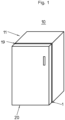
- FIG. 1 a perspective view of a closed refrigerator and/or freezer 10 is shown.
- the refrigerator and/or freezer 10 comprises a body 11 and at least one closure element 20 which closes an opening in the body 11.
- a gap 19 can be seen between the closure element 20 and the body 11, in which a profile arrangement 1 is arranged.
- the profile arrangement 1 can be arranged both on the closure element 20 and on the body 11 of the refrigerator and/or freezer 10.
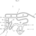
- FIG. 2 a sectional view of a further profile arrangement 1 of a refrigerator and/or freezer 10 according to the invention is shown.
- the refrigerator and/or freezer 10 has a body 11, which is formed by the wall 13 in this exemplary embodiment.
- the wall 13 of the body 11 has a first wall element 130, which is made of metal and on which a second wall element 131 is arranged, which consists of a polymeric material and which are connected to one another in a force-fitting manner.
- the closure element 20 is arranged, which in this exemplary embodiment has a first closure part 21, which is made of a metallic material and a second closure part 22 arranged thereon, which is made of a polymeric material .
- a groove is arranged in the second closure part 22 of the closure element 20, in which the fastening arrangement 2 of the profile arrangement 1 is arranged.
- the profile arrangement 1 comprises a base 8, a fastening arrangement 2, at least one sealing arrangement 3 and a profile element 5.
- the profile arrangement 1 has a magnetic element 100 in its hollow chamber 30, which is made of a soft magnetic material and, when used as intended, serves to be between the first wall element 130 of the wall 13 of the body 11, and the profile arrangement 1, a non-positive connection is established by the magnetic force of the magnetic element 15.
- the profile arrangement 1 is arranged between the body 11 and the closure element 20 of the refrigerator and/or freezer 10 in such a way that the profile element 5 closes the gap 19 almost over the entire surface.
- the free end 51 of the profile element 5 is arranged on the sealing arrangement 3, the free end 52 of the profile element 5 being connected via at least one movement arrangement 4 which projects at least partially into the sealing arrangement 3 with the base 8.
- the profile arrangement 1 comprises a base 8, a fastening arrangement 2, a sealing arrangement 3 and a profile element 5.
- the free end 51 of the profile element 5 is arranged on the sealing arrangement 3 and the further free end 52 of the profile element 5 is connected to the base via at least one 8 is connected via at least one movement arrangement 4 which projects at least partially into the sealing arrangement 3 and which has at least two movement sections 40, 41 arranged approximately opposite one another.
- the sealing arrangement 3 of the profile arrangement 1 has at least one insulation element 15, which is arranged at a distance from the profile element 5 via at least one hollow chamber 35 and is integrally connected thereto and is designed as a web.
- the insulation element 15 designed as a web is arranged parallel to the profile element 5 on the sealing arrangement 3.
- the insulation element 15 designed as a web is approximately linear, approximately prismatic in cross section and has a wall thickness of approximately 0.5 mm.
- the insulation element 15 designed as a web is further designed so that it has a length of approximately 15 mm between its free ends.
- the profile arrangement 1 it is surprisingly possible with the profile arrangement 1 to effectively prevent or reduce possible heat input from the surrounding area of the refrigerator and/or freezer 10 via the gap 19 through the insulation element 15 designed as a web.
- the insulation element 15 designed as a web is made of a polymeric material, like the sealing arrangement 3. Therefore, due to the inherent material properties, it represents a poor heat conductor in the sense of the heat input from the surrounding space into the refrigerator and / or freezer 10.
- a further advantage of the refrigerator and/or freezer 10 according to the invention is that the insulation element 15 designed as a web is arranged at a distance from the profile element 5 or the sealing arrangement 3 of the profile arrangement 1 via the hollow chamber 35.
- the thickness of the insulation element 15 designed as a web and the width or volume of the hollow chamber 35 it is possible for the first time to effectively reduce or completely prevent heat input via the gap 19 of the refrigerator and/or freezer 10.
- the profile arrangement 1 of the refrigerator and/or freezer 10 according to the invention is designed such that a further sealing element 9 is arranged on the sealing arrangement 3 directly on the hollow chamber 31, which additionally covers the gap between the second wall element 131 of the body 11 and the second closure part 22 of the closure element 20 closes energetically effectively.
- the refrigerator and/or freezer 10 it is also possible to prevent the cold/temperature existing in the interior of the body 11 of the refrigerator and/or freezer 10 from being released into the interior via the sealing arrangement 3 of the profile arrangement 1 and the gap 19 .
- the profile arrangement 1 is further designed such that the free end 52 of the profile element 5 is arranged at a distance from the base 8 via a movement arrangement 4 which at least partially projects into the sealing arrangement 3.
- the profile arrangement 1 is further designed such that the profile element 5 is connected to the sealing arrangement 3 via a stiffening element 6.
- the profile element 5 is connected to the hollow chamber 30 of the sealing arrangement 3 via a stiffening element 6.
- the movement arrangement 4 of the profile arrangement 1 is designed to protrude into the sealing arrangement 3 at approximately an acute angle relative to the profile element 5.
- the movement arrangement 4 has two movement sections 40, 41 arranged opposite one another, which are connected to one another via a connecting element 42.
- the first movement section 40 is formed approximately parallel to the second movement section 41 of the movement arrangement 4.
- the profile arrangement 1 is further designed such that the base 8 is arranged approximately orthogonally to the profile element 5 and the fastening arrangement 2 is arranged on the base 8 in a materially bonded manner at approximately a right angle.
- FIG. 3 a sectional view of another profile arrangement 1 of a refrigerator and/or freezer is shown.
- the profile arrangement 1 comprises a base 8, a fastening arrangement 2, a sealing arrangement 3 and a profile element 5.
- the free end 51 of the profile element 5 is arranged on the sealing arrangement 3, in particular on the hollow chamber 30, while the free end 52 of the profile element 5 has at least one movement arrangement 4, with the base 8 via at least one movement arrangement 4 which at least partially protrudes into the sealing arrangement 3 , connected is.
- the profile arrangement 1 is designed such that the sealing arrangement 3 has at least one insulation element 15, which is arranged at a distance from the profile element 5 via at least one hollow chamber 34 and is integrally connected thereto and is designed as a web.
- the insulation element 15 designed as a web is arranged approximately parallel to the profile element 5 on the sealing arrangement 3.
- the insulation element 15 designed as a web is approximately linear, approximately prismatic in cross section and has a wall thickness of approximately 0.4 mm.
- the insulation element 15 designed as a web is arranged with its one free end on the hollow chamber 30 of the sealing arrangement 3 and with its oppositely arranged further free end on the movement section 40 of the movement arrangement 4.
- the profile arrangement 1 is designed such that the insulation element 15 designed as a web separates the hollow chamber 32 of the sealing arrangement 3 and a further hollow chamber 34 through which the insulation element 15 designed as a web is arranged at a distance from the profile element 5.
- the profile arrangement 1 when used as intended in a refrigerator and/or freezer according to the invention, it is surprisingly possible to effectively reduce heat input from the room into the interior or a cold output from the interior of the refrigerator and/or freezer into the room .
- the profile arrangement 1 of the refrigerator and/or freezer according to the invention is further designed such that a further sealing element 9 is arranged on the hollow chamber 31 of the sealing arrangement 3.
- the profile arrangement 1 of the refrigerator and/or freezer according to the invention has a cover element 7 on the profile element 5, which is arranged in one piece on the free end 52 of the profile element 5.
- FIG. 4 a sectional view of another profile arrangement 1 of a refrigerator and/or freezer is shown.
- the profile arrangement 1 has a base 8, a fastening arrangement 2, a sealing arrangement 3 and a profile element 5.
- the free end 51 of the profile element 5 is arranged on the sealing arrangement 3, the free end 52 of the profile element 5 being connected via at least one fastening arrangement 4 which projects at least partially into the sealing arrangement 3 and is connected to the base 8 via at least one fastening arrangement 4.
- the profile arrangement 1 is designed such that the sealing arrangement 3 has at least one insulation element 15, which is arranged at a distance from the profile element 5 via at least one hollow chamber 34, 35 and is integrally connected thereto and is designed as a web.
- the profile arrangement is designed in such a way that the sealing arrangement 3 has an insulating element 15 which is arranged over the hollow chamber 35 at a distance from the profile element 5 and is connected in one piece and is designed as a web.
- the insulation element 15 designed as a web is curved:
- the insulation element 15 designed as a web has a curvature that projects outwards from the sealing arrangement 3 and is therefore convex.
- the profile arrangement 1 is designed such that the sealing arrangement 3 has at least one insulation element 15 which is arranged at a distance from the profile element 5 via a hollow chamber 34 and is integrally connected thereto and designed as a web.
- the profile arrangement 1 in this exemplary embodiment is further designed such that a further hollow chamber 36 is arranged between the hollow chamber 30 and 31 on the sealing arrangement 3.
- the profile arrangement 1 is further designed in such a way that a further hollow chamber 33 is formed on the hollow chamber 31 of the sealing arrangement 3, which is formed by a further wall section of the sealing arrangement 3.
- the profile arrangement 1 is designed such that the insulation element 15, which is designed as a web and is arranged at a distance from the profile element 5 via the hollow chamber 34, is arranged on the sealing arrangement 3 at approximately an acute/obtuse angle.
- the insulation element 15 has a wall thickness of approximately 0.3 mm.
- the insulation element 15, designed as a web, has a length of approximately 12 mm between its free ends.
- the insulation element 15 designed as a web has a wall thickness of approximately 0.5 mm. Furthermore, the insulation element 15 designed as a web has a length of approximately 35 mm between its free ends.
- the profile arrangement 1 is designed such that the insulation element 15, which is arranged at a distance from the profile element 5 via the hollow chamber 35 and is designed as a web, has a cover element 7 at its free end.
- the profile arrangement 1 When used as intended or in the installed state, it is surprisingly possible with the profile arrangement 1 to provide refrigerators and/or freezers according to the invention in which the gap between the closure element and the body can be covered in a visually appealing manner, with the required tolerance compensation between the closure element as well as the body with an optimized profile stroke of a profile arrangement and in particular to successfully reduce or prevent the heat input into or the cold output from the device.
Landscapes
- Engineering & Computer Science (AREA)
- Chemical & Material Sciences (AREA)
- Combustion & Propulsion (AREA)
- Physics & Mathematics (AREA)
- Mechanical Engineering (AREA)
- Thermal Sciences (AREA)
- General Engineering & Computer Science (AREA)
- Refrigerator Housings (AREA)
Description
- Die Erfindung betrifft das technische Gebiet der Kühl- und / oder Gefriergeräte, umfassend wenigstens einen Korpus und wenigstens ein, eine Öffnung des Korpus verschließendes, Verschlusselement, sowie wenigstens einer, in einem zwischen dem Verschlusselement und dem Korpus gebildeten Spalt angeordneten, Profilanordnung gemäß den Merkmalen des Obergriffes des Anspruches 1.
- Derartige Kühl- und / oder Gefriergeräte sind im Stand der Technik bereits beschrieben. Bei Kühl-und / oder Gefriergeräten haben Profilanordnungen die wichtige Funktion, den konstruktiv bedingten Spalt zwischen dem Verschlusselement und einem Korpus abzudichten, Toleranzen auszugleichen und im Falle des Einsatzes von Magnetprofilanordnungen das Verschließen der Kühlgerätetür am Korpus mittels Magnethaftkraft zu gewährleisten. Dabei erfolgt bei den Profilanordnungen der Toleranzausgleich sowie der Hub der Profilanordnung mittels Balgkonstruktionen, welche im Sichtbereich dieser Profilanordnungen deutlich erkennbar sind.
- So offenbart die
EP 0 599 161 B1 eine derartiges Kühl- und / oder Gefriergerät. Eine Profilanordnung ist hierbei als Dichtungsanordnung ausgebildet für die Tür eines Kühl- oder Gefriergerätes, mit einem wärmeisolierenden Gehäuse, dessen Öffnung mit einer Tür verschließbar ist, die an ihrer der Öffnung zugewandten, mit einer Innenverkleidung ausgestatteten Seite eine am Rand der Tür umlaufend angeordnete, balgartige Magnetdichtung aufweist, die mit einem Dichtungskopf und einem Dichtungsfuß ausgestattet ist, die miteinander mit flexiblen, als Dehnfalten ausgebildeten Wandungen verbunden sind, wobei der Dichtungsfuß in einer öffnungsseitig sich verjüngenden, zur Türöffnung gerichteten Aufnahmenut an der Innenverkleidung verankert ist, während der mit Magnetleisten ausgestattete Dichtungskopf im geschlossenen Zustand der Tür am Öffnungsrand des Gehäuses aufliegt und die Tür am Öffnungsrand festhält, wobei der Dichtungskopf zum Dichtungsfuß seitlich versetzt angeordnet ist, welcher mit einer einseitigen Ausbauchung ausgestattet ist, welche mit einem Hinterschnitt in der Aufnahmenut zusammenwirkt und welche entgegengesetzt zum seitlichen Versatz näher am Dichtungskopf angeordnet ist, wobei sich die der Ausbauchung gegenüberliegende Seite des Dichtungsfußes in der Aufnahmenut abstützt, wobei der Dichtungsfuß mit einem Einführkeil versehen ist und auf seiner der Ausbauchung gegenüberliegenden Seite einen Vorsprung aufweist, welchem in Wesentlichen höhengleich zum Maximum der Ausbauchung angeordnet ist und welcher in der Aufnahmenut sich unter einer geringen Vorspannung am Wandabschnitt der Aufnahmenut abstützt. Dabei sind die als Dehnfalten ausgebildeten Wandungen von der die Magnetleiste aufnehmenden Hohlkammer des Dichtungskopfes beabstandet angeordnet. - Eine weiteres gattungsgemäßes Kühl- und / oder Gefriergerät ist in der
DE 601 15 098 T2 offenbart. Hierbei ist eine Profilanordnung als verbesserte Dichtungsanordnung für Kühlschränke und ähnliches mit einem aus Kunststoffmaterial hergestellten Profil ausgebildet, wobei die Anordnung aus einem Schrank, einer Tür und einem Innentürfeldelement, welches mit dem Schrank gekoppelt werden kann und einem Abschnitt einer Balgdichtung besteht, welche einen abgedichteten Verschluss zwischen der Tür und dem Schrank bereitstellt, wobei vorgesehen ist, dass ein Profil und der Dichtungsabschnitt zusammengepasst sind oder ein einzelnes integrales Teil ausbilden, welches durch Koextrusion von zwei Materialien, welche verschiedene Festigkeitsgrade aufweisen, hergestellt ist, um so, falls nötig, ein bequemes Ablösen des Dichtungsabschnitts vom Profil entlang des Bereichs ihrer Verbindung zu ermöglichen, wobei das Profil eine Rille, die dazu ausgestattet ist, einen Ersatzabschnitt einer Balgdichtung aufzunehmen und wenigstens einen elastisch nachgiebigen Seitenabschnitt aufweist, welcher wirkt, um eine Schnappverbindung zwischen dem Profil und dem Innentürfeldelement bereitzustellen, wobei der Abschnitt mit einer gerillten Aufnahme endet, welche einen im Wesentlichen C-förmigen Querschnitt aufweist und so ausgestaltet ist, um eine Kante des Innentürfeldelements aufzunehmen, wobei man sich weiter vorstellt, dass das Profil eine Basis aufweist, welche an gegenüberliegenden Enden mit Dichtungsstreifen versehen ist, die mit der Tür und dem Innentürfeldelement zusammenwirken, wobei an der gerillten Aufnahme, welche einen im Wesentlichen C-förmigen Querschnitt aufweist, wenigstens ein Dichtstreifen vorgesehen ist, welcher aus einem weichen Material hergestellt ist und gegenüberliegend der Kante des Innentürfeldelements eingerichtet ist, sodass, wenn das Innentürfeldelement wirksam mit dem Profil gekoppelt ist, der Dichtungsstreifen unter der Wirkung einer elastischen Rückstellung des Abschnitts gegen die Kante des Innentürfeldelements zusammengedrückt wird, wobei man sich weiter vorstellt, dass ein Krümmungsbereich im rechten Winkel des Innentürfeldelements einen Radius von etwa 3 bis 6 mm aufweist, um so eine optimale Kontrastwirkung mit einem der Dichtungsstreifen der Basis des Profils sicherzustellen. - Der Dichtungsabschnitt ist weiter so ausgebildet, dass er eine dehnbare Kammer festlegt, die als ein Balg wirkt und eine obere Kammer aufweist, die ausgestaltet ist um einen Stab aus magnetischem Material aufzunehmen. Zwischen der oberen Kammer bzw. der dehnbaren Kammer und dem der Dichtungsanordnung ist ein Spalt ausgebildet.
- Nachteilig bei dem Stand der Technik ist, dass einerseits die bei geschlossenen Kühl-und/oder Gefriergeräten dem Betrachter entgegentretende Optik im Spalt zwischen der Tür und dem Korpus des Kühl- und/oder Gefriergerätes durch diese Dichtungsanordnung optisch nicht ansprechend wirken und dass andererseits der Wärmeingang in bzw. der Kälteausgang aus dem Kühl- und / oder Gefriergerät nicht wirksam sowie effektiv verhinderbar ist.
- Ein weiterer Nachteil aus dem Stand der Technik besteht darin, dass die energetische Wirksamkeit bei Kühl- und / oder Gefriergeräten nicht optimierbar bzw. verbesserbar ist.
- Die
WO 2017/108189 A1 offenbart ein weiteres gattungsgemäßes Kühl- und / oder Gefriergerät, umfassend wenigstens einen Korpus und wenigstens ein, eine Öffnung des Korpus verschließendes, Verschlusselement, sowie wenigstens einer, in einem zwischen dem Verschlusselement und dem Korpus gebildeten Spalt, angeordneten Profilanordnung umfassend eine Basis, wenigstens eine Befestigungsanordnung, wenigstens eine Dichtungsanordnung sowie wenigstens ein Profilelement, wobei wenigstens ein freies Ende des Profilelements an der Dichtungsanordnung angeordnet ist, wobei wenigstens ein weiteres freies Ende des Profilelements über wenigstens ein, mit der Basis über wenigstens eine, in die Dichtungsanordnung wenigstens teilweise hineinragende, Bewegungsanordnung, welche wenigstens zwei einander etwa gegenüberliegend angeordnete Bewegungsabschnitte aufweist, verbunden ist, wobei die Dichtungsanordnung wenigsten ein, über wenigstens eine Hohlkammer beabstandet zum Profilelement angeordnetes, einstückig damit verbundenes, als Steg ausgebildetes Isolationselement aufweist. - Hier setzt die Erfindung ein, die sich die Aufgabe gestellt hat, ein Kühl- und / oder Gefriergerät zur Verfügung zu stellen, welches die Nachteile des bekannten Standes der Technik erfolgreich überwindet, das wirtschaftlich und kostengünstig herstellbar ist, bei dem der konstruktiv bedingte Spalt zwischen Verschlusselement und Korpus des Kühl- und / oder Gefriergerätes optisch ansprechend abdeckbar ist und das einen Wärmeingang in bzw. einen Kälteausgang aus dem Gerät erfolgreich verhindert.
- Erfindungsgemäß wird dies durch ein Kühl- und / oder Gefriergerät mit den Merkmalen des Anspruches 1 gelöst. Weitere vorteilhafte Ausgestaltungen sind in den Unteransprüchen beschrieben.
- Es hat sich überraschend herausgestellt, dass ein Kühl- und / oder Gefriergerät, umfassend wenigstens einen Korpus und wenigstens ein, eine Öffnung des Korpus verschließendes Verschlusselement, sowie wenigstens einer, in einer zwischen dem Verschlusselement und dem Korpus gebildeten Spalt, angeordneten Profilanordnung umfassend eine Basis, wenigstens eine Befestigungsanordnung, wenigstens eine Dichtungsanordnung sowie wenigstens ein Profilelement, wobei wenigstens ein freies Ende des Profilelements an der Dichtungsanordnung angeordnet ist, wobei wenigstens ein weiteres freies Ende des Profilelementes über wenigstens ein, mit der Basis über wenigstens eine, in die Dichtungsanordnung wenigstens teilweise hineinragende, Bewegungsanordnung, welche wenigstens zwei einander etwa gegenüberliegend angeordnete Bewegungsabschnitte aufweist, verbunden ist, wobei die Dichtungsanordnung wenigstens einen, über wenigstens eine Hohlkammer beabstandet zum Profilelement angeordneten, einstückig damit verbundenen, als Steg ausgebildetes Isolationselement aufweist, sich dadurch auszeichnet, dass das als Steg ausgebildetes Isolationselement parallel zum Profilelement an der Dichtungsanordnung angeordnet ist. Durch diese vorteilhafte Ausgestaltung kann bei dem erfindungsgemäßen Kühl- und / oder Gefriergerät, welches nicht nur wirtschaftlich und kostengünstig herstellbar ist, sondern welches einen Wärmeingang in bzw. einen Kälteausgang aus dem Gerät energetisch wirksam verhindert.
- Überraschenderweise hat sich weiterhin gezeigt, dass ein Kühl- und / oder Gefriergerät, umfassend wenigstens einen Korpus und wenigstens einem, eine Öffnung des Korpus verschließenden Verschlusselement, sowie wenigstens einer, in einem zwischen dem Verschlusselement und dem Korpus gebildeten Spalt, angeordneten Profilanordnung umfassend eine Basis, wenigstens eine Befestigungsanordnung, wenigstens eine Dichtungsanordnung sowie wenigstens ein Profilelement, wobei wenigstens ein freies Ende des Profilelements an der Dichtungsanordnung angeordnet ist, wobei wenigstens ein weiteres freies Ende des Profilelements über wenigstens eine, an der Dichtungsanordnung wenigstens teilweise angeordnete, Bewegungsanordnung, von der Basis beabstandet, angeordnet ist, sich dadurch auszeichnet, dass die Dichtungsanordnung wenigstens einen, über wenigstens eine Hohlkammer beabstandet zum Profilelement angeordneten, einstückig damit verbundenen, als Steg ausgebildetes Isolationselement aufweist.
- Bei dem erfindungsgemäßen Kühl- und / oder Gefriergerät ist es somit erstmals möglich, den Spalt zwischen dem Verschlusselement und dem Korpus optisch ansprechend abzudecken, den erforderlichen Toleranzausgleich zwischen dem Verschlusselement sowie dem Korpus mit einem optimierten Profilhub einer Profilanordnung zu realisieren und insbesondere den Wärmeeingang in bzw. den Kälteausgang aus dem Gerät erfolgreich zu verhindern.
- Dabei hat es sich weiterhin als vorteilhaft herausgestellt bei dem erfindungsgemäßen Kühl-und / oder Gefriergerät, dass das als Steg ausgebildetes Isolationselement etwa linear, im Querschnitt etwa prismatisch ausgebildet ist und eine Wandstärke von etwa 0,1 bis 10 mm, vorzugsweise 0,25 bis 5 mm aufweist. Somit können erstmals erfindungsgemäße Kühl- und / oder Gefriergeräte zur Verfügung gestellt werden, die unabhängig von dem zu kühlenden Volumen im Korpus einen Wärmeeingang in bzw. einen Kälteausgang aus dem Gerät wirksam verhindern.
- Es hat sich weiterhin vorteilhaft herausgestellt, dass das als Steg ausgebildetes Isolationselement zwischen seinen freien Enden eine Breite von etwa 5 bis 50 mm, vorzugsweise etwa 7 bis 40 mm aufweist. Hierdurch kann einerseits durch die Position und insbesondere durch die Geometrie des als Steg ausgebildetes Isolationselement ein erfindungsgemäßes Kühl- und / oder Gefriergerät zur Verfügung gestellt werden, bei dem ein Wärmedurchgang bzw. Kälteeingang erfolgreich verhindert bzw. reduzierbar ist.
- Bei dem erfindungsgemäßen Kühl- und / oder Gefriergerät ist das als Steg ausgebildetes Isolationselement vorteilhafterweise so ausgebildet, dass es einen Wärmedurchlasswiderstand R gemäß EN ISO 6946 von etwa 30 bis 450 (m2·K) / W, bevorzugt etwa 40 bis 400 (m2·K) / W, besonders bevorzugt etwa 50 bis 350 (m2·K) / W bei einer Wanddicke von etwa 1,5 bis 10 mm aufweist. Der Wärmedurchlasswiderstand R insbesondere als Steg ausgebildetes Isolationselementes charakterisiert das Verhältnis der Dicke zur Wärmeleitfähigkeit gemäß EN ISO 6946 Bauteile. Es hat sich überraschend herausgestellt, dass durch die Geometrie / Dicke als auch die Auswahl des Werkstoffes des als Steg ausgebildetes Isolationselementes des erfindungsgemäßen Kühl- und / oder Gefriergerätes ein gegenüber dem Stand der Technik überraschend hoher Wärmedurchlasswiderstand erzielbar ist. Somit ist es mit der erfindungsgemäßen Kühl- und / oder Gefriergerät erstmals möglich, den bisher energetisch ungünstigen Spalt zwischen dem Verschlusselement und dem Korpus eines Kühl- und / oder Gefriergerätes und der darin angeordneten Profilanordnung so zu gestalten, dass aufgrund des hohen Wärmedurchlasswiderstandes gemäß EN ISO 6946 eine Energieeinsparung bei einem Kühl- und / oder Gefriergerät realisierbar ist.
- Weiterhin hat sich überraschend herausgestellt bei dem erfindungsgemäßen Kühl- und / oder Gefriergerät, dass ein derart als Steg ausgebildetes Isolationselement beispielsweise aus einem organischen Material hergestellt, eine sehr niedrige Wärmeleitfähigkeit aufweist. Hierdurch wird eine nachhaltige Verbesserung der Wärmedämmeigenschaften des erfindungsgemäßen Kühl- und / oder Gefriergerätes bei bestimmungsgemäßen Einsatz einer Profilanordnung mit wenigstens einem als Steg ausgebildeten Isolationselementes an einem Verschlusselement und / oder einem Korpus eines Kühl- und / oder Gefriergerätes realisiert.
- Das als Steg ausgebildetes Isolationselement aus einem Werkstoff hergestellt ist ausgewählt aus der Gruppe wie Polyvinylchlorid (PVC); Polyolefin, wie Polypropylen (PP) oder Polyethylen (PE); styrolbasiertes Polymer, wie Polystyrol (PS) oder Styrol-Butadien-Copolymer mit überwiegendem Styrolanteil (SB) oder Acrylnitril-Styrol-Acrylester-Copolymere (ASA) oder Acrylnitril-Butadien-Styrol-Copolymere (ABS) oder Styrolacrylnitril (SAN); Polybutylentherephthalat (PBT); Polyethylentherephthalat (PET); Polyoxymethylen (POM); Polyamid (PA); Polymethylmethacrylat (PMMA); Polytetrafluorethylen (PTFE); Polyurethan (PUR); sowie Mischungen aus wenigstens zwei dieser Materialien. Hierdurch ist eine kostengünstige und wirtschaftliche Herstellung der Profilanordnung für ein erfindungsgemäßes Kühl- und / oder Gefriergerät möglich. Dies auch bei gleichzeitiger Beibehaltung des erforderlichen Toleranzausgleiches zwischen dem Verschlusselement und / oder dem Korpus eines Kühl- und / oder Gefriergerätes. Weiterhin ist ein möglicher Wärmeeingang in bzw. Kälteausgang aus dem Kühl- und / oder Gefriergerät erfolgreich verhindert.
- In einer weiteren vorteilhaften Ausgestaltung des erfindungsgemäßen Kühl- und / oder Gefriergerätes ist das als Steg ausgebildetes Isolationselement an wenigstens einer Hohlkammer der Dichtungsanordnung angeordnet. Hierdurch lässt sich ein erfindungsgemäßes Kühl- und / oder Gefriergerät zur Verfügung stellen, welches wirtschaftlich und kostengünstig herstellbar ist und welches beim bestimmungsgemäßen Einsatz einen Wärmeingang in bzw. einen Kälteausgang aus dem Gerät effektiv und wirksam verhindert.
- Weiterhin vorteilhaft bei dem erfindungsgemäßen Kühl- und / oder Gefriergerät ist, dass das Profilelement der Profilanordnung über wenigstens ein Versteifungselement mit der Dichtungsanordnung verbunden ist. Hierdurch ist vorteilhafterweise erreichbar, dass bei bestimmungsgemäßer Verwendung des Kühl- und / oder Gefriergerätes neben dem optisch ansprechenden Verschluss des Spaltes auch sichergestellt ist, dass beim Öffnen und Schließen des Verschlusselements eine Stabilisierung der Dichtungsanordnung realisierbar ist.
- Ebenfalls vorteilhaft bei dem erfindungsgemäßen Kühl- und / oder Gefriergerätes ist, dass das als Steg ausgebildetes Isolationselement über wenigstens ein Versteifungselement mit wenigstens einer Hohlkammer der Dichtungsanordnung verbunden ist. In dieser vorteilhaften Ausgestaltung ist das erfindungsgemäße Kühl- und / oder Gefriergerät so konzipiert, dass bei bestimmungsgemäßem Einsatz die Funktion insbesondere der Profilanordnung hinsichtlich der thermischen Abdichtung optimiert bzw. der Festigkeit, unter Beibehaltung der Funktionalität der Profilanordnung, stabilisiert ist.
- Es hat sich weiterhin als vorteilhaft bei dem erfindungsgemäßen Kühl- und / oder Gefriergerät herausgestellt, dass das als Steg ausgebildetes Isolationselement wenigstens ein Abdeckelement aufweist. Durch diese vorteilhafte Ausgestaltung der Profilanordnung ist es erstmals möglich, dass bei bestimmungsgemäßem Einsatz an einem Verschlusselement und / oder einem Korpus eines Kühl- und / oder Gefriergerätes die bestehenden Toleranzunterschiede unmittelbar optisch ansprechend abdeckbar sind.
- Dabei hat es sich weiter als vorteilhaft herausgestellt bei dem erfindungsgemäßen Kühl-und / oder Gefriergerät, dass die wenigstens eine Bewegungsanordnung der Profilanordnung in etwa einem spitzen Winkel bezogen zum Profilelement in die Dichtungsanordnung hineinragt. Hierdurch kann ein erfindungsgemäßes Kühl- und / oder Gefriergerät zur Verfügung gestellt werden, bei dem bei bestimmungsgemäßem Gebrauch die für das Abdichten erforderliche Funktion der Profilanordnung von außen durch den Nutzer nicht mehr sichtbar ist, ohne das die mechanische und insbesondere die thermische Funktionalität eingeschränkt ist.
- Dabei hat es sich weiterhin als vorteilhaft bei dem erfindungsgemäßen Kühl- und / oder Gefriergerät herausgestellt, dass die wenigstens eine Bewegungsanordnung der Profilanordnung wenigstens zwei einander etwa gegenüberliegend angeordnete, über wenigstens ein Verbindungselement miteinander verbundene Bewegungsabschnitte aufweist. Durch diese vorteilhafte Ausgestaltung der Profilanordnung ist es bei bestimmungsgemäßer Verwendung erstmals möglich, den Spalt zwischen dem Verschlusselement und dem Korpus eines erfindungsgemäßen Kühl- und / oder Gefriergerätes so optisch ansprechend und thermisch wirksam abzudecken, dass insbesondere auch toleranzbedingte Spaltmaßunterschiede optimal überdeckbar sind.
- Ein weiterer Vorteil des erfindungsgemäßen Kühl- und / oder Gefriergerätes besteht darin, dass die Dichtungsanordnung und / oder die Bewegungsanordnung und / oder das Profilelement und / oder das als Steg ausgebildetes Isolationselement aus einem weichelastischen, polymeren Werkstoff hergestellt ist, mit einer Härte Shore A gemäß DIN EN ISO 868 von etwa 50 bis 100, bevorzugt 60 bis 90. Durch die Variation der einzelnen polymeren Werkstoffe der Dichtungsanordnung und / oder der Bewegungsanordnung und / oder des Profilelements und / oder des als Steg ausgebildeten Isolationselementes können alle derzeit bekannten Abmessungen eines Spaltes zwischen dem Verschlusselement und dem Korpus eines erfindungsgemäßen Kühl- und / oder Gefriergerätes optisch ansprechend bei voller mechanischer Funktionalität und thermischer Isolierung erstmals realisiert werden.
- Das erfindungsgemäße Kühl- und / oder Gefriergerät sowie die Profilanordnung sollen nun an Ausführungsbeispielen, die diese nicht einschränken, näher beschrieben werden.
- Es zeigen:
- Fig. 1:
- perspektivische Darstellung eines verschlossenen Kühl- und / oder Gefriergerätes;
- Fig. 2:
- Schnittdarstellung einer Profilanordnung in ihrem Einbauzustand eines erfindungsgemäßen Kühl- und / oder Gefriergerätes;
- Fig. 3:
- Schnittdarstellung einer weiteren Profilanordnung eines Kühl- und / oder Gefriergerätes;
- Fig. 4:
- Schnittdarstellung einer weiteren Profilanordnung eines Kühl- und / oder Gefriergerätes.
- In der
Fig. 1 ist eine perspektivische Darstellung eines verschlossenen Kühl- und / oder Gefriergerätes 10 dargestellt. - Das Kühl- und / oder Gefriergerät 10 umfasst einen Korpus 11 und wenigstens ein, eine Öffnung des Korpus 11 verschließendes, Verschlusselement 20.
- Zwischen dem Verschlusselement 20 sowie dem Korpus 11 ist ein Spalt 19 erkennbar, in dem eine Profilanordnung 1 angeordnet ist.
- Die Profilanordnung 1 kann dabei sowohl am Verschlusselement 20 als auch am Korpus 11 des Kühl- und / oder Gefriergerätes 10 angeordnet sein.
- In der
Fig. 2 ist eine Schnittdarstellung einer weiteren Profilanordnung 1 eines erfindungsgemäßen Kühl- und / oder Gefriergerätes 10 dargestellt. - Das Kühl- und/oder Gefriergerät 10 weist einen Korpus 11 auf, der in diesem Ausführungsbeispiel durch die Wand 13 gebildet ist.
- Die Wand 13 des Korpus 11 weist ein erstes Wandelement 130 auf, welches aus Metall hergestellt ist und an dem ein zweites Wandelement 131 angeordnet ist, welches aus einem polymeren Werkstoff besteht und die miteinander kraftschlüssig verbunden sind.
- Gegenüber dem Korpus 11 des Kühl- und/oder Gefriergerät 10 ist das Verschlusselement 20 angeordnet, welches in diesem Ausführungsbeispiel ein erstes Verschlussteil 21, welches aus einem metallischen Werkstoff hergestellt ist und ein daran angeordnetes zweites Verschlussteil 22 aufweist, welches aus einem polymeren Werkstoff hergestellt ist.
- Im zweiten Verschlussteil 22 des Verschlusselements 20 ist eine Nut angeordnet, in der die Befestigungsanordnung 2 der Profilanordnung 1 angeordnet ist.
- Die Profilanordnung 1 umfasst eine Basis 8, eine Befestigungsanordnung 2, wenigstens eine Dichtungsanordnung 3 sowie ein Profilelement 5.
- Die Profilanordnung 1 weist in diesem Ausführungsbeispiel in ihrer Hohlkammer 30 ein Magnetelement 100 auf, welche aus einem weichmagnetischen Werkstoff hergestellt ist und bei bestimmungsgemäßer Verwendung dazu dient, dass zwischen dem ersten Wandelement 130 der Wand 13 des Korpus 11, und der Profilanordnung 1 eine kraftschlüssige Verbindung durch die Magnetkraft des Magnetelementes 15 hergestellt ist.
- In diesem Ausführungsbeispiel ist die Profilanordnung 1 so zwischen dem Korpus 11 und dem Verschlusselement 20 des Kühl- und / oder Gefriergerätes 10 angeordnet, dass das Profilelement 5 den Spalt 19 nahezu vollflächig verschließt.
- Das freie Ende 51 des Profilelementes 5 ist an der Dichtungsanordnung 3 angeordnet, wobei das freie Ende 52 des Profilelements 5 über wenigstens ein, mit der Basis 8 über wenigstens eine, in die Dichtungsanordnung 3 wenigstens teilweise hineinragende, Bewegungsanordnung 4, verbunden ist.
- Die Profilanordnung 1 umfasst eine Basis 8, eine Befestigungsanordnung 2, eine Dichtungsanordnung 3 sowie ein Profilelement 5. Das freie Ende 51 des Profilelements 5 ist an der Dichtungsanordnung 3 angeordnet und das weitere freie Ende 52 des Profilelements 5 ist über wenigstens ein, mit der Basis 8 über wenigstens eine, in die Dichtungsanordnung 3 wenigstens teilweise hineinragende, Bewegungsanordnung 4, welche wenigstens zwei einander etwa gegenüberliegend angeordnete Bewegungsabschnitte 40, 41 aufweist verbunden.
- Die Dichtungsanordnung 3 der Profilanordnung 1 weist in diesem Ausführungsbeispiel wenigstens ein, über wenigstens eine Hohlkammer 35 beabstandet zum Profilelement 5 angeordnetes, einstückig damit verbundenes, als Steg ausgebildetes Isolationselement 15 auf. Das als Steg ausgebildete Isolationselement 15 ist in diesem Ausführungsbeispiel parallel zum Profilelement 5 an der Dichtungsanordnung 3 angeordnet.
- Weiterhin ist das als Steg ausgebildete Isolationselement 15 etwa linear, im Querschnitt etwa prismatisch ausgebildet und weist eine Wandstärke von etwa 0,5 mm auf.
- Das als Steg ausgebildete Isolationselement 15 ist weiter so ausgebildet, dass es zwischen seinen freien Enden eine Länge von etwa 15 mm aufweist.
- In dieser vorteilhaften Ausgestaltung ist es mit der Profilanordnung 1 überraschenderweise möglich, einen möglichen Wärmeeingang aus dem Umgebungsbereich des Kühl- und / oder Gefriergerätes 10 über den Spalt 19 wirksam durch das als Steg ausgebildete Isolationselement 15 zu verhindern bzw. zu reduzieren.
- Das als Steg ausgebildete Isolationselement 15 ist dabei aus einem polymeren Werkstoff hergestellt, wie die Dichtungsanordnung 3. Somit stellt es aus den immanenten Materialeigenschaften heraus einen schlechten Wärmeleiter im Sinne des Wärmeeinganges von dem Umgebungsraum in das Kühl- und / oder Gefriergerät 10 dar.
- Ein weiterer Vorteil des erfindungsgemäßen Kühl- und / oder Gefriergerätes 10 besteht darin, dass das als Steg ausgebildete Isolationselement 15 über die Hohlkammer 35 vom Profilelement 5 bzw. der Dichtungsanordnung 3 der Profilanordnung 1 beabstandet angeordnet ist.
- Durch die Dimensionierung der Dicke der als Steg ausgebildeten Isolationselement 15 sowie die Breite bzw. das Volumen der Hohlkammer 35 ist es erstmals möglich, insbesondere einen Wärmeeingang über den Spalt 19 des Kühl- und / oder Gefriergerätes 10 wirksam zu reduzieren bzw. ganz zu verhindern.
- Weiterhin ist die Profilanordnung 1 des erfindungsgemäßen Kühl- und / oder Gefriergerätes 10 so ausgebildet, dass an der Dichtungsanordnung 3 direkt an der Hohlkammer 31 ein weiteres Dichtelement 9 angeordnet ist, welches zusätzlich den Spalt zwischen dem zweiten Wandelement 131 des Korpus 11 und dem zweiten Verschlussteil 22 des Verschlusselements 20 energetisch wirksam verschließt.
- Somit ist zusätzlich bei dem erfindungsgemäßen Kühl- und / oder Gefriergerät 10 verhinderbar, dass die im Innenraum des Korpus 11 des Kühl- und / oder Gefriergerätes 10 bestehende Kälte / Temperatur über die Dichtungsanordnung 3 der Profilanordnung 1 und den Spalt 19 in den Innenraum abgebbar ist.
- Insbesondere durch das etwa parallel zum Profilelement 5, als Steg ausgebildete Isolationselement 15 und die Hohlkammer 35 der Dichtungsanordnung 3 kann ein Wärmeeingang über den Spalt 19 in das Innere des Kühl- und / oder Gefriergerätes 10 verhindert bzw. ein Kälteausgang aus dem Kühl- und / oder Gefriergerät 10 ebenfalls wirksam reduziert bzw. verhindert werden.
- Die Profilanordnung 1 ist weiterhin so ausgebildet, dass das freie Ende 52 des Profilelementes 5 über eine, in die Dichtungsanordnung 3 wenigstens teilweise hineinragende, Bewegungsanordnung 4 von der Basis 8 beabstandet, angeordnet ist.
- Die Profilanordnung 1 ist weiterhin so ausgebildet, dass das Profilelement 5 über ein Versteifungselement 6 mit der Dichtungsanordnung 3 verbunden ist.
- In diesem Ausführungsbeispiel ist das Profilelement 5 über ein Versteifungselement 6 mit der Hohlkammer 30 der Dichtungsanordnung 3 verbunden.
- Die Bewegungsanordnung 4 der Profilanordnung 1 ist in diesem Ausführungsbeispiel in etwa einem spitzen Winkel bezogen zum Profilelement 5 in die Dichtungsanordnung 3 hineinragend, ausgebildet. Die Bewegungsanordnung 4 weist in diesem Ausführungsbeispiel zwei einander gegenüberliegend angeordnete Bewegungsabschnitte 40, 41 auf, die über ein Verbindungselement 42 miteinander verbunden sind.
- In diesem Ausführungsbeispiel ist der erste Bewegungsabschnitt 40 in etwa parallel zum zweiten Bewegungsabschnitt 41 der Bewegungsanordnung 4 ausgebildet.
- Die Profilanordnung 1 ist weiter so ausgebildet, dass die Basis 8 etwa orthogonal zum Profilelement 5 angeordnet ist und die Befestigungsanordnung 2 an der Basis 8 stoffschlüssig in etwa einem rechten Winkel angeordnet ist.
- In der
Fig. 3 ist eine Schnittdarstellung einer weiteren Profilanordnung 1 eines Kühl- und / oder Gefriergerätes dargestellt. - Die Profilanordnung 1 umfasst eine Basis 8, eine Befestigungsanordnung 2, eine Dichtungsanordnung 3 sowie ein Profilelement 5.
- Das freie Ende 51 des Profilelements 5 ist an der Dichtungsanordnung 3, insbesondere an der Hohlkammer 30 angeordnet, während das freie Ende 52 des Profilelements 5 über wenigstens ein, mit der Basis 8 über wenigstens eine, in die Dichtungsanordnung 3 wenigstens teilweise hineinragende, Bewegungsanordnung 4, verbunden ist.
- In diesem Ausführungsbeispiel ist die Profilanordnung 1 so ausgebildet, dass die Dichtungsanordnung 3 wenigstens ein, über wenigstens eine Hohlkammer 34 beabstandet zum Profilelement 5 angeordnetes, einstückig damit verbundenes, als Steg ausgebildetes Isolationselement 15 aufweist.
- Das als Steg ausgebildete Isolationselement 15 ist etwa parallel zum Profilelement 5 an der Dichtungsanordnung 3 angeordnet.
- In diesem Ausführungsbeispiel ist das als Steg ausgebildete Isolationselement 15 etwa linear, im Querschnitt etwa prismatisch ausgebildet und weist eine Wandstärke von etwa 0,4 mm auf.
- Weiterhin ist das als Steg ausgebildete Isolationselement 15 in diesem Ausführungsbeispiel mit seinem einen freien Ende an der Hohlkammer 30 der Dichtungsanordnung 3 sowie mit seinem gegenüberliegend angeordneten weiteren freien Ende an dem Bewegungsabschnitt 40 der Bewegungsanordnung 4 angeordnet.
- In diesem Ausführungsbeispiel ist die Profilanordnung 1 so ausgebildet, dass das als Steg ausgebildete Isolationselement 15 die Hohlkammer 32 der Dichtungsanordnung 3 trennt und eine weitere Hohlkammer 34, durch welche das als Steg ausgebildete Isolationselement 15 vom Profilelement 5 beabstandet angeordnet ist.
- Insbesondere bei bestimmungsgemäßem Einsatz der Profilanordnung 1 in einem erfindungsgemäßen Kühl- und / oder Gefriergerät ist es somit überraschenderweise möglich, einen Wärmeeingang aus dem Raum in das Innere bzw. einen Kälteausgang aus dem Inneren des Kühl- und / oder Gefriergerätes in den Raum wirksam zu reduzieren.
- Die Profilanordnung 1 des erfindungsgemäßen Kühl- und / oder Gefriergerätes ist weiterhin so ausgebildet, dass an der Hohlkammer 31 der Dichtungsanordnung 3 ein weiteres Dichtelement 9 angeordnet ist.
- Weiterhin weist die Profilanordnung 1 des erfindungsgemäßen Kühl- und / oder Gefriergerätes am Profilelement 5 ein Abdeckelement 7 auf, welches einstückig am freien Ende 52 des Profilelements 5 angeordnet ist.
- In der
Fig. 4 ist eine Schnittdarstellung einer weiteren Profilanordnung 1 eines Kühl- und / oder Gefriergerätes dargestellt. - Die Profilanordnung 1 weist eine Basis 8, eine Befestigungsanordnung 2, eine Dichtungsanordnung 3 sowie ein Profilelement 5 auf.
- Das freie Ende 51 des Profilelements 5 ist an der Dichtungsanordnung 3 angeordnet, wobei das freie Ende 52 des Profilelements 5 über wenigstens ein, mit der Basis 8 über wenigstens eine, in die Dichtungsanordnung 3 wenigstens teilweise hineinragende, Befestigungsanordnung 4 verbunden ist.
- In diesem Ausführungsbeispiel ist die Profilanordnung 1 so ausgebildet, dass die Dichtungsanordnung 3 wenigstens ein, über wenigstens eine Hohlkammer 34, 35 beabstandet zum Profilelement 5 angeordnetes, einstückig damit verbundenes, als Steg ausgebildetes Isolationselement 15 aufweist.
- In diesem Ausführungsbeispiel ist die Profilanordnung so ausgebildet, dass die Dichtungsanordnung 3 über ein, über die Hohlkammer 35 beabstandet zum Profilelement 5 angeordnetes, einstückig damit verbundenes, als Steg ausgebildetes Isolationselement 15 aufweist. Das als Steg ausgebildete Isolationselement 15 ist gekrümmt ausgebildet: Das als Steg ausgebildete Isolationselement 15 weist eine nach außen von der Dichtungsanordnung 3 wegragende Krümmung auf, ist also konvex ausgebildet.
- Weiterhin ist die Profilanordnung 1 so ausgebildet, dass die Dichtungsanordnung 3 wenigstens ein über eine Hohlkammer 34 zum Profilelement 5 beabstandet angeordnetes, einstückig damit verbundenes, als Steg ausgebildetes Isolationselement 15 aufweist.
- Die Profilanordnung 1 in diesem Ausführungsbeispiel weiterhin so ausgebildet, dass zwischen der Hohlkammer 30 und 31 an die Dichtungsanordnung 3 eine weitere Hohlkammer 36 angeordnet ist.
- Die Profilanordnung 1 ist in diesem Ausführungsbeispiel weiter so ausgebildet, dass an der Hohlkammer 31 der Dichtungsanordnung 3 eine weitere Hohlkammer 33 ausgebildet ist, die von einem weiteren Wandabschnitt der Dichtungsanordnung 3 gebildet ist.
- Bei bestimmungsgemäßer Verwendung der Profilanordnung 1 in einem erfindungsgemäßen Kühl- und / oder Gefriergerät ist es überraschenderweise möglich, im Einbauzustand gemäß der
Fig. 2 , einen Wärmeeingang aus dem umgebenden Raum über den nicht dargestellten Spalt des Kühl- und / oder Gefriergerätes wirksam über die als Steg ausgebildeten Isolationselemente, welche über die Hohlkammer 34, 35 vom Profilelement 5 beabstandet angeordnet sind, zu verhindern. - In diesem Ausführungsbeispiel ist die Profilanordnung 1 so ausgebildet, dass das als Steg ausgebildete Isolationselement 15, welches über die Hohlkammer 34 vom Profilelement 5 beabstandet angeordnet ist, in etwa einem spitzen / stumpfen Winkel an der Dichtungsanordnung 3 angeordnet ist.
- Das Isolationselement 15 weist in diesem Ausführungsbeispiel eine Wanddicke von ca. 0,3 mm auf. Das als Steg ausgebildete Isolationselement 15 weist zwischen seinen freien Enden eine Länge von etwa 12 mm auf.
- Das als Steg ausgebildete Isolationselement 15, welches über die Hohlkammer 35 beabstandet zum Profilelement 5 angeordnet ist, ist in diesem Ausführungsbeispiel parallel zum Profilelement 5 angeordnet.
- Das als Steg ausgebildete Isolationselement 15 weist in diesem Ausführungsbeispiel eine Wandstärke von etwa 0,5 mm auf. Weiterhin weist das als Steg ausgebildete Isolationselement 15 zwischen seinen freien Enden eine Länge von etwa 35 mm auf.
- Weiterhin ist die Profilanordnung 1 so ausgebildet, dass das über die Hohlkammer 35 vom Profilelement 5 beabstandet angeordnete, als Steg ausgebildete, Isolationselement 15 an seinem freien Ende ein Abdeckelement 7 aufweist.
- Bei bestimmungsgemäßem Einsatz bzw. im Einbauzustand ist es mit der Profilanordnung 1 überraschenderweise möglich, erfindungsgemäße Kühl- und / oder Gefriergeräte zur Verfügung zu stellen, bei denen der Spalt zwischen dem Verschlusselement und dem Korpus optisch ansprechend abdeckbar ist, wobei der erforderliche Toleranzausgleich zwischen dem Verschlusselement sowie dem Korpus mit einem optimierten Profilhub einer Profilanordnung realisierbar ist und insbesondere den Wärmeeingang in bzw. den Kälteausgang aus dem Gerät erfolgreich zu reduzieren bzw. auch zu verhindern.
Claims (7)
- Kühl- und / oder Gefriergerät (10), umfassend wenigstens einen Korpus (11) und wenigstens ein, eine Öffnung des Korpus (11) verschließendes, Verschlusselement (20), sowie wenigstens einer, in einem zwischen dem Verschlusselement (20) und dem Korpus (11) gebildeten Spalt (19), angeordneten Profilanordnung (1) umfassend eine Basis (8), wenigstens eine Befestigungsanordnung (2), wenigstens eine Dichtungsanordnung (3) sowie wenigstens ein Profilelement (5), wobei wenigstens ein freies Ende (51) des Profilelements (5) an der Dichtungsanordnung (3) angeordnet ist, wobei wenigstens ein weiteres freies Ende (52) des Profilelements (5) über wenigstens ein, mit der Basis (8) über wenigstens eine, in die Dichtungsanordnung (3) wenigstens teilweise hineinragende, Bewegungsanordnung (4), welche wenigstens zwei einander etwa gegenüberliegend angeordnete Bewegungsabschnitte (40, 41) aufweist, verbunden ist, wobei die Dichtungsanordnung (3) wenigsten ein, über wenigstens eine Hohlkammer (34, 35) beabstandet zum Profilelement (5) angeordnetes, einstückig damit verbundenes, als Steg ausgebildetes Isolationselement (15) aufweist, dadurch gekennzeichnet, dass als Steg ausgebildetes Isolationselement (15) parallel zum Profilelement (5) an der Dichtungsanordnung (3) angeordnet ist, dass das als Steg ausgebildete Isolationselement (15) einen Wärmedurchlasswiderstand R gemäß EN ISO 6946 von etwa 30 bis 450 (m2·K) / W, bevorzugt etwa 40 bis 400 (m2·K) / W, besonders bevorzugt etwa 50 bis 350 (m2·K) / W bei einer Wanddicke von etwa 1,5 bis 10 mm aufweist.
- Kühl- und / oder Gefriergerät (10) nach Anspruch 1, dass das als Steg ausgebildetes Isolationselement (15) etwa linear, im Querschnitt etwa prismatisch ausgebildet ist und eine Wandstärke von etwa 0,1 bis10 mm, vorzugsweise etwa 0,25 bis 5 mm aufweist.
- Kühl- und / oder Gefriergerät (10) nach einem der vorhergehenden Ansprüche, dadurch gekennzeichnet, dass das als Steg ausgebildetes Isolationselement (15) zwischen seinen freien Enden eine Länge von etwa 5 bis 50 mm, vorzugsweise etwa 7 bis 40 mm aufweist.
- Kühl- und / oder Gefriergerät (10) nach einem der vorhergehenden Ansprüche, dadurch gekennzeichnet, dass das als Steg ausgebildete Isolationselement (15) eine Wärmeleitfähigkeit von vorzugsweise 0,02 bis 0,15 W / (m·K), vorzugsweise etwa 0,02 bis 0,08 W / (m·K) aufweist.
- Kühl- und / oder Gefriergerät (10) nach einem der vorhergehenden Ansprüche, dadurch gekennzeichnet, dass das als Steg ausgebildetes Isolationselement (15) an wenigstens einer Hohlkammer (30, 31, 32, 33, 34, 35, 36) der Dichtungsanordnung (3) angeordnet ist.
- Kühl- und / oder Gefriergerät (10) nach einem der vorhergehenden Ansprüche, dadurch gekennzeichnet, dass das als Steg ausgebildetes Isolationselement (15) wenigstens ein Abdeckelement (7) aufweist.
- Kühl- und / oder Gefriergerät (10) nach einem der vorhergehenden Ansprüche, dadurch gekennzeichnet, dass die Dichtungsanordnung (3) und / oder die Bewegungsanordnung (4) und / oder das Profilelement (5) und/oder das als Steg ausgebildetes Isolationselement (15) aus einem weichelastischem, polymeren Werkstoff hergestellt ist, mit einer Härte Shore A gemäß DIN EN ISO 868 von etwa 50 bis 100, bevorzugt 60 bis 90.
Applications Claiming Priority (1)
| Application Number | Priority Date | Filing Date | Title |
|---|---|---|---|
| DE202017107822.1U DE202017107822U1 (de) | 2017-12-21 | 2017-12-21 | Kühl- und / oder Gefriergerät |
Publications (2)
| Publication Number | Publication Date |
|---|---|
| EP3502602A1 EP3502602A1 (de) | 2019-06-26 |
| EP3502602B1 true EP3502602B1 (de) | 2023-11-01 |
Family
ID=64664115
Family Applications (1)
| Application Number | Title | Priority Date | Filing Date |
|---|---|---|---|
| EP18211250.8A Active EP3502602B1 (de) | 2017-12-21 | 2018-12-10 | Kühl- und/oder gefriergerät |
Country Status (2)
| Country | Link |
|---|---|
| EP (1) | EP3502602B1 (de) |
| DE (1) | DE202017107822U1 (de) |
Families Citing this family (2)
| Publication number | Priority date | Publication date | Assignee | Title |
|---|---|---|---|---|
| DE102018207625A1 (de) | 2018-05-16 | 2019-11-21 | BSH Hausgeräte GmbH | Dichtelement mit Abschlussteil in Form eines Ringabschnitts, Tür mit einem Dichtelement sowie Haushaltsgerät |
| DE202019105890U1 (de) * | 2019-10-23 | 2021-01-26 | Rehau Ag + Co | Profilanordnung, insbesondere für ein Kühl- und / oder Gefriergerät |
Family Cites Families (6)
| Publication number | Priority date | Publication date | Assignee | Title |
|---|---|---|---|---|
| DE59308866D1 (de) | 1992-11-27 | 1998-09-17 | Bosch Siemens Hausgeraete | Dichtungsanordnung, insbesondere für die Tür eines Kühl- oder Gefriergerätes |
| IT1281660B1 (it) * | 1996-01-15 | 1998-02-26 | Ilpea Ind Spa | Profilo perfezionato di materia plastica per mobili frigoriferi e simili |
| ITMI20010472A1 (it) | 2001-03-07 | 2002-09-07 | Ilpea Ind Spa | Insieme di tenuta migliorato per mobili frigoriferi e simili con profilo di materia plastica |
| CA2438766C (en) * | 2003-08-29 | 2008-12-30 | Maytag Corporation | Refrigerator incorporating french doors with rotating mullion bar |
| WO2014171905A1 (en) * | 2013-04-18 | 2014-10-23 | Conta Elastik Urunler San. Ve Tic. A.S. | A coated and foamed sealing member |
| DE202015107071U1 (de) * | 2015-12-23 | 2017-03-27 | Rehau Ag + Co | Kühl- und / oder Gefriergerät |
-
2017
- 2017-12-21 DE DE202017107822.1U patent/DE202017107822U1/de not_active Expired - Lifetime
-
2018
- 2018-12-10 EP EP18211250.8A patent/EP3502602B1/de active Active
Also Published As
| Publication number | Publication date |
|---|---|
| DE202017107822U1 (de) | 2019-03-25 |
| EP3502602A1 (de) | 2019-06-26 |
Similar Documents
| Publication | Publication Date | Title |
|---|---|---|
| EP3394533B1 (de) | Profilanordnung, insbesondere für ein kühl- und/oder gefriergerät | |
| EP3394534B1 (de) | Kühl- und/oder gefriergerät | |
| EP2952839A1 (de) | Tür für ein haushaltsgerät sowie haushaltsgerät | |
| EP3502602A1 (de) | Kühl- und/oder gefriergerät | |
| EP3669130B1 (de) | Kältegerät | |
| EP3379181A1 (de) | Haushaltgerätevorrichtung mit einem Korpus, einem Verschlusselement sowie einer an dem Korpus und an dem Verschlusselement befestigthen Leitung | |
| EP3569757B2 (de) | Dichtelement mit einem abschlussteil in der form eines ringabschnitts, tür mit einem dichtelement sowie ein haushaltsgerät | |
| EP2682555A2 (de) | Eckverbindungselement | |
| DE102007008707A1 (de) | Kühlgerät | |
| EP0660056B1 (de) | Türblatt für ein thermisch isoliertes Fach, insbesondere ein Kühlfach eines Kühlmöbels | |
| EP1110045B1 (de) | Tür eines kühl- oder gefriergerätes mit einer dichtung | |
| EP4048967B1 (de) | Profilanordnung, insbesondere für ein kühl- und/oder gefriergerät | |
| DE102010003460B4 (de) | Kältegerät, insbesondere Standkältegerät | |
| DE102014206948A1 (de) | Haushaltskältegerät | |
| DE102018130766A1 (de) | Profilanordnung, insbesondere für ein Kühl- und / oder Gefriergerät | |
| DE102010003459B4 (de) | Kältegerät, insbesondere Standkältegerät | |
| EP3655714B1 (de) | Kältegerät mit umströmten verdampfer | |
| DE102007061039A1 (de) | Schließkraftunterstützte Verriegelungsvorrichtung | |
| EP3163232A1 (de) | Kältegerät mit hinterlegteil und verfahren zum herstellen eines kältegerätes mit hinterlegteil | |
| DE102010030440A1 (de) | Kältegerät, insbesondere Haushaltskältegerät | |
| EP2746704B1 (de) | Haushaltskältegerät mit einem nicht-geradlinig verlaufenden Luftspalt zwischen einer Gefrierfach-Tür und einer benachbarten Gefrierfach-Wand | |
| DE102019132750A1 (de) | Profilanordnung, insbesondere für ein Kühl- und/oder Gefriergerät | |
| EP2955468B1 (de) | Türabstandshalter und haushaltsgerät mit einem türabstandshalter | |
| EP2193946B1 (de) | Dichtungsprofil | |
| AT17515U1 (de) | Fensterbankabschluss |
Legal Events
| Date | Code | Title | Description |
|---|---|---|---|
| PUAI | Public reference made under article 153(3) epc to a published international application that has entered the european phase |
Free format text: ORIGINAL CODE: 0009012 |
|
| STAA | Information on the status of an ep patent application or granted ep patent |
Free format text: STATUS: THE APPLICATION HAS BEEN PUBLISHED |
|
| AK | Designated contracting states |
Kind code of ref document: A1 Designated state(s): AL AT BE BG CH CY CZ DE DK EE ES FI FR GB GR HR HU IE IS IT LI LT LU LV MC MK MT NL NO PL PT RO RS SE SI SK SM TR |
|
| AX | Request for extension of the european patent |
Extension state: BA ME |
|
| STAA | Information on the status of an ep patent application or granted ep patent |
Free format text: STATUS: REQUEST FOR EXAMINATION WAS MADE |
|
| 17P | Request for examination filed |
Effective date: 20191127 |
|
| RBV | Designated contracting states (corrected) |
Designated state(s): AL AT BE BG CH CY CZ DE DK EE ES FI FR GB GR HR HU IE IS IT LI LT LU LV MC MK MT NL NO PL PT RO RS SE SI SK SM TR |
|
| RAP1 | Party data changed (applicant data changed or rights of an application transferred) |
Owner name: REHAU AG + CO |
|
| STAA | Information on the status of an ep patent application or granted ep patent |
Free format text: STATUS: EXAMINATION IS IN PROGRESS |
|
| 17Q | First examination report despatched |
Effective date: 20211007 |
|
| RAP1 | Party data changed (applicant data changed or rights of an application transferred) |
Owner name: REHAU INDUSTRIES SE & CO. KG |
|
| RAP3 | Party data changed (applicant data changed or rights of an application transferred) |
Owner name: REHAU INDUSTRIES SE & CO. KG |
|
| GRAP | Despatch of communication of intention to grant a patent |
Free format text: ORIGINAL CODE: EPIDOSNIGR1 |
|
| STAA | Information on the status of an ep patent application or granted ep patent |
Free format text: STATUS: GRANT OF PATENT IS INTENDED |
|
| INTG | Intention to grant announced |
Effective date: 20230717 |
|
| GRAS | Grant fee paid |
Free format text: ORIGINAL CODE: EPIDOSNIGR3 |
|
| GRAA | (expected) grant |
Free format text: ORIGINAL CODE: 0009210 |
|
| STAA | Information on the status of an ep patent application or granted ep patent |
Free format text: STATUS: THE PATENT HAS BEEN GRANTED |
|
| AK | Designated contracting states |
Kind code of ref document: B1 Designated state(s): AL AT BE BG CH CY CZ DE DK EE ES FI FR GB GR HR HU IE IS IT LI LT LU LV MC MK MT NL NO PL PT RO RS SE SI SK SM TR |
|
| REG | Reference to a national code |
Ref country code: GB Ref legal event code: FG4D Free format text: NOT ENGLISH |
|
| REG | Reference to a national code |
Ref country code: CH Ref legal event code: EP |
|
| REG | Reference to a national code |
Ref country code: DE Ref legal event code: R096 Ref document number: 502018013548 Country of ref document: DE |
|
| REG | Reference to a national code |
Ref country code: IE Ref legal event code: FG4D Free format text: LANGUAGE OF EP DOCUMENT: GERMAN |
|
| REG | Reference to a national code |
Ref country code: LT Ref legal event code: MG9D |
|
| REG | Reference to a national code |
Ref country code: NL Ref legal event code: MP Effective date: 20231101 |
|
| PG25 | Lapsed in a contracting state [announced via postgrant information from national office to epo] |
Ref country code: GR Free format text: LAPSE BECAUSE OF FAILURE TO SUBMIT A TRANSLATION OF THE DESCRIPTION OR TO PAY THE FEE WITHIN THE PRESCRIBED TIME-LIMIT Effective date: 20240202 |
|
| PG25 | Lapsed in a contracting state [announced via postgrant information from national office to epo] |
Ref country code: IS Free format text: LAPSE BECAUSE OF FAILURE TO SUBMIT A TRANSLATION OF THE DESCRIPTION OR TO PAY THE FEE WITHIN THE PRESCRIBED TIME-LIMIT Effective date: 20240301 |
|
| PG25 | Lapsed in a contracting state [announced via postgrant information from national office to epo] |
Ref country code: LT Free format text: LAPSE BECAUSE OF FAILURE TO SUBMIT A TRANSLATION OF THE DESCRIPTION OR TO PAY THE FEE WITHIN THE PRESCRIBED TIME-LIMIT Effective date: 20231101 |
|
| PG25 | Lapsed in a contracting state [announced via postgrant information from national office to epo] |
Ref country code: NL Free format text: LAPSE BECAUSE OF FAILURE TO SUBMIT A TRANSLATION OF THE DESCRIPTION OR TO PAY THE FEE WITHIN THE PRESCRIBED TIME-LIMIT Effective date: 20231101 |
|
| PG25 | Lapsed in a contracting state [announced via postgrant information from national office to epo] |
Ref country code: ES Free format text: LAPSE BECAUSE OF FAILURE TO SUBMIT A TRANSLATION OF THE DESCRIPTION OR TO PAY THE FEE WITHIN THE PRESCRIBED TIME-LIMIT Effective date: 20231101 |
|
| PG25 | Lapsed in a contracting state [announced via postgrant information from national office to epo] |
Ref country code: NL Free format text: LAPSE BECAUSE OF FAILURE TO SUBMIT A TRANSLATION OF THE DESCRIPTION OR TO PAY THE FEE WITHIN THE PRESCRIBED TIME-LIMIT Effective date: 20231101 Ref country code: LT Free format text: LAPSE BECAUSE OF FAILURE TO SUBMIT A TRANSLATION OF THE DESCRIPTION OR TO PAY THE FEE WITHIN THE PRESCRIBED TIME-LIMIT Effective date: 20231101 Ref country code: IS Free format text: LAPSE BECAUSE OF FAILURE TO SUBMIT A TRANSLATION OF THE DESCRIPTION OR TO PAY THE FEE WITHIN THE PRESCRIBED TIME-LIMIT Effective date: 20240301 Ref country code: GR Free format text: LAPSE BECAUSE OF FAILURE TO SUBMIT A TRANSLATION OF THE DESCRIPTION OR TO PAY THE FEE WITHIN THE PRESCRIBED TIME-LIMIT Effective date: 20240202 Ref country code: ES Free format text: LAPSE BECAUSE OF FAILURE TO SUBMIT A TRANSLATION OF THE DESCRIPTION OR TO PAY THE FEE WITHIN THE PRESCRIBED TIME-LIMIT Effective date: 20231101 Ref country code: BG Free format text: LAPSE BECAUSE OF FAILURE TO SUBMIT A TRANSLATION OF THE DESCRIPTION OR TO PAY THE FEE WITHIN THE PRESCRIBED TIME-LIMIT Effective date: 20240201 Ref country code: PT Free format text: LAPSE BECAUSE OF FAILURE TO SUBMIT A TRANSLATION OF THE DESCRIPTION OR TO PAY THE FEE WITHIN THE PRESCRIBED TIME-LIMIT Effective date: 20240301 |
|
| PG25 | Lapsed in a contracting state [announced via postgrant information from national office to epo] |
Ref country code: SE Free format text: LAPSE BECAUSE OF FAILURE TO SUBMIT A TRANSLATION OF THE DESCRIPTION OR TO PAY THE FEE WITHIN THE PRESCRIBED TIME-LIMIT Effective date: 20231101 Ref country code: RS Free format text: LAPSE BECAUSE OF FAILURE TO SUBMIT A TRANSLATION OF THE DESCRIPTION OR TO PAY THE FEE WITHIN THE PRESCRIBED TIME-LIMIT Effective date: 20231101 Ref country code: PL Free format text: LAPSE BECAUSE OF FAILURE TO SUBMIT A TRANSLATION OF THE DESCRIPTION OR TO PAY THE FEE WITHIN THE PRESCRIBED TIME-LIMIT Effective date: 20231101 Ref country code: NO Free format text: LAPSE BECAUSE OF FAILURE TO SUBMIT A TRANSLATION OF THE DESCRIPTION OR TO PAY THE FEE WITHIN THE PRESCRIBED TIME-LIMIT Effective date: 20240201 Ref country code: LV Free format text: LAPSE BECAUSE OF FAILURE TO SUBMIT A TRANSLATION OF THE DESCRIPTION OR TO PAY THE FEE WITHIN THE PRESCRIBED TIME-LIMIT Effective date: 20231101 Ref country code: HR Free format text: LAPSE BECAUSE OF FAILURE TO SUBMIT A TRANSLATION OF THE DESCRIPTION OR TO PAY THE FEE WITHIN THE PRESCRIBED TIME-LIMIT Effective date: 20231101 |
|
| PG25 | Lapsed in a contracting state [announced via postgrant information from national office to epo] |
Ref country code: DK Free format text: LAPSE BECAUSE OF FAILURE TO SUBMIT A TRANSLATION OF THE DESCRIPTION OR TO PAY THE FEE WITHIN THE PRESCRIBED TIME-LIMIT Effective date: 20231101 |
|
| PG25 | Lapsed in a contracting state [announced via postgrant information from national office to epo] |
Ref country code: CZ Free format text: LAPSE BECAUSE OF FAILURE TO SUBMIT A TRANSLATION OF THE DESCRIPTION OR TO PAY THE FEE WITHIN THE PRESCRIBED TIME-LIMIT Effective date: 20231101 |
|
| PG25 | Lapsed in a contracting state [announced via postgrant information from national office to epo] |
Ref country code: SK Free format text: LAPSE BECAUSE OF FAILURE TO SUBMIT A TRANSLATION OF THE DESCRIPTION OR TO PAY THE FEE WITHIN THE PRESCRIBED TIME-LIMIT Effective date: 20231101 |
|
| PG25 | Lapsed in a contracting state [announced via postgrant information from national office to epo] |
Ref country code: SM Free format text: LAPSE BECAUSE OF FAILURE TO SUBMIT A TRANSLATION OF THE DESCRIPTION OR TO PAY THE FEE WITHIN THE PRESCRIBED TIME-LIMIT Effective date: 20231101 Ref country code: SK Free format text: LAPSE BECAUSE OF FAILURE TO SUBMIT A TRANSLATION OF THE DESCRIPTION OR TO PAY THE FEE WITHIN THE PRESCRIBED TIME-LIMIT Effective date: 20231101 Ref country code: IT Free format text: LAPSE BECAUSE OF FAILURE TO SUBMIT A TRANSLATION OF THE DESCRIPTION OR TO PAY THE FEE WITHIN THE PRESCRIBED TIME-LIMIT Effective date: 20231101 Ref country code: EE Free format text: LAPSE BECAUSE OF FAILURE TO SUBMIT A TRANSLATION OF THE DESCRIPTION OR TO PAY THE FEE WITHIN THE PRESCRIBED TIME-LIMIT Effective date: 20231101 Ref country code: DK Free format text: LAPSE BECAUSE OF FAILURE TO SUBMIT A TRANSLATION OF THE DESCRIPTION OR TO PAY THE FEE WITHIN THE PRESCRIBED TIME-LIMIT Effective date: 20231101 Ref country code: CZ Free format text: LAPSE BECAUSE OF FAILURE TO SUBMIT A TRANSLATION OF THE DESCRIPTION OR TO PAY THE FEE WITHIN THE PRESCRIBED TIME-LIMIT Effective date: 20231101 |
|
| REG | Reference to a national code |
Ref country code: CH Ref legal event code: PL |
|
| REG | Reference to a national code |
Ref country code: DE Ref legal event code: R097 Ref document number: 502018013548 Country of ref document: DE |
|
| PG25 | Lapsed in a contracting state [announced via postgrant information from national office to epo] |
Ref country code: LU Free format text: LAPSE BECAUSE OF NON-PAYMENT OF DUE FEES Effective date: 20231210 |
|
| PG25 | Lapsed in a contracting state [announced via postgrant information from national office to epo] |
Ref country code: MC Free format text: LAPSE BECAUSE OF FAILURE TO SUBMIT A TRANSLATION OF THE DESCRIPTION OR TO PAY THE FEE WITHIN THE PRESCRIBED TIME-LIMIT Effective date: 20231101 |
|
| REG | Reference to a national code |
Ref country code: BE Ref legal event code: MM Effective date: 20231231 |
|
| PG25 | Lapsed in a contracting state [announced via postgrant information from national office to epo] |
Ref country code: MC Free format text: LAPSE BECAUSE OF FAILURE TO SUBMIT A TRANSLATION OF THE DESCRIPTION OR TO PAY THE FEE WITHIN THE PRESCRIBED TIME-LIMIT Effective date: 20231101 Ref country code: LU Free format text: LAPSE BECAUSE OF NON-PAYMENT OF DUE FEES Effective date: 20231210 |
|
| PLBE | No opposition filed within time limit |
Free format text: ORIGINAL CODE: 0009261 |
|
| STAA | Information on the status of an ep patent application or granted ep patent |
Free format text: STATUS: NO OPPOSITION FILED WITHIN TIME LIMIT |
|
| 26N | No opposition filed |
Effective date: 20240802 |
|
| REG | Reference to a national code |
Ref country code: IE Ref legal event code: MM4A |
|
| PG25 | Lapsed in a contracting state [announced via postgrant information from national office to epo] |
Ref country code: IE Free format text: LAPSE BECAUSE OF NON-PAYMENT OF DUE FEES Effective date: 20231210 |
|
| PG25 | Lapsed in a contracting state [announced via postgrant information from national office to epo] |
Ref country code: BE Free format text: LAPSE BECAUSE OF NON-PAYMENT OF DUE FEES Effective date: 20231231 |
|
| PG25 | Lapsed in a contracting state [announced via postgrant information from national office to epo] |
Ref country code: FR Free format text: LAPSE BECAUSE OF NON-PAYMENT OF DUE FEES Effective date: 20240101 |
|
| PG25 | Lapsed in a contracting state [announced via postgrant information from national office to epo] |
Ref country code: CH Free format text: LAPSE BECAUSE OF NON-PAYMENT OF DUE FEES Effective date: 20231231 |
|
| GBPC | Gb: european patent ceased through non-payment of renewal fee |
Effective date: 20240201 |
|
| PG25 | Lapsed in a contracting state [announced via postgrant information from national office to epo] |
Ref country code: SI Free format text: LAPSE BECAUSE OF FAILURE TO SUBMIT A TRANSLATION OF THE DESCRIPTION OR TO PAY THE FEE WITHIN THE PRESCRIBED TIME-LIMIT Effective date: 20231101 |
|
| PG25 | Lapsed in a contracting state [announced via postgrant information from national office to epo] |
Ref country code: SI Free format text: LAPSE BECAUSE OF FAILURE TO SUBMIT A TRANSLATION OF THE DESCRIPTION OR TO PAY THE FEE WITHIN THE PRESCRIBED TIME-LIMIT Effective date: 20231101 Ref country code: IE Free format text: LAPSE BECAUSE OF NON-PAYMENT OF DUE FEES Effective date: 20231210 Ref country code: FR Free format text: LAPSE BECAUSE OF NON-PAYMENT OF DUE FEES Effective date: 20240101 Ref country code: CH Free format text: LAPSE BECAUSE OF NON-PAYMENT OF DUE FEES Effective date: 20231231 Ref country code: BE Free format text: LAPSE BECAUSE OF NON-PAYMENT OF DUE FEES Effective date: 20231231 |
|
| PG25 | Lapsed in a contracting state [announced via postgrant information from national office to epo] |
Ref country code: GB Free format text: LAPSE BECAUSE OF NON-PAYMENT OF DUE FEES Effective date: 20240201 |
|
| PG25 | Lapsed in a contracting state [announced via postgrant information from national office to epo] |
Ref country code: GB Free format text: LAPSE BECAUSE OF NON-PAYMENT OF DUE FEES Effective date: 20240201 |
|
| PG25 | Lapsed in a contracting state [announced via postgrant information from national office to epo] |
Ref country code: RO Free format text: LAPSE BECAUSE OF FAILURE TO SUBMIT A TRANSLATION OF THE DESCRIPTION OR TO PAY THE FEE WITHIN THE PRESCRIBED TIME-LIMIT Effective date: 20231101 |
|
| PG25 | Lapsed in a contracting state [announced via postgrant information from national office to epo] |
Ref country code: FI Free format text: LAPSE BECAUSE OF FAILURE TO SUBMIT A TRANSLATION OF THE DESCRIPTION OR TO PAY THE FEE WITHIN THE PRESCRIBED TIME-LIMIT Effective date: 20231101 |
|
| PG25 | Lapsed in a contracting state [announced via postgrant information from national office to epo] |
Ref country code: CY Free format text: LAPSE BECAUSE OF FAILURE TO SUBMIT A TRANSLATION OF THE DESCRIPTION OR TO PAY THE FEE WITHIN THE PRESCRIBED TIME-LIMIT; INVALID AB INITIO Effective date: 20181210 |
|
| PG25 | Lapsed in a contracting state [announced via postgrant information from national office to epo] |
Ref country code: HU Free format text: LAPSE BECAUSE OF FAILURE TO SUBMIT A TRANSLATION OF THE DESCRIPTION OR TO PAY THE FEE WITHIN THE PRESCRIBED TIME-LIMIT; INVALID AB INITIO Effective date: 20181210 |
|
| PGFP | Annual fee paid to national office [announced via postgrant information from national office to epo] |
Ref country code: TR Payment date: 20250915 Year of fee payment: 8 |
|
| PGFP | Annual fee paid to national office [announced via postgrant information from national office to epo] |
Ref country code: AT Payment date: 20251120 Year of fee payment: 8 |
|
| PGFP | Annual fee paid to national office [announced via postgrant information from national office to epo] |
Ref country code: DE Payment date: 20251231 Year of fee payment: 8 |