EP3502595B1 - Vorrichtung und verfahren zur kühlung von produkten - Google Patents
Vorrichtung und verfahren zur kühlung von produkten Download PDFInfo
- Publication number
- EP3502595B1 EP3502595B1 EP17208688.6A EP17208688A EP3502595B1 EP 3502595 B1 EP3502595 B1 EP 3502595B1 EP 17208688 A EP17208688 A EP 17208688A EP 3502595 B1 EP3502595 B1 EP 3502595B1
- Authority
- EP
- European Patent Office
- Prior art keywords
- conveyor
- cooling gas
- cooling
- aperture
- products
- Prior art date
- Legal status (The legal status is an assumption and is not a legal conclusion. Google has not performed a legal analysis and makes no representation as to the accuracy of the status listed.)
- Active
Links
Images
Classifications
-
- F—MECHANICAL ENGINEERING; LIGHTING; HEATING; WEAPONS; BLASTING
- F25—REFRIGERATION OR COOLING; COMBINED HEATING AND REFRIGERATION SYSTEMS; HEAT PUMP SYSTEMS; MANUFACTURE OR STORAGE OF ICE; LIQUEFACTION SOLIDIFICATION OF GASES
- F25D—REFRIGERATORS; COLD ROOMS; ICE-BOXES; COOLING OR FREEZING APPARATUS NOT OTHERWISE PROVIDED FOR
- F25D13/00—Stationary devices, e.g. cold-rooms
- F25D13/06—Stationary devices, e.g. cold-rooms with conveyors carrying articles to be cooled through the cooling space
- F25D13/067—Stationary devices, e.g. cold-rooms with conveyors carrying articles to be cooled through the cooling space with circulation of gaseous cooling fluid
-
- B—PERFORMING OPERATIONS; TRANSPORTING
- B65—CONVEYING; PACKING; STORING; HANDLING THIN OR FILAMENTARY MATERIAL
- B65G—TRANSPORT OR STORAGE DEVICES, e.g. CONVEYORS FOR LOADING OR TIPPING, SHOP CONVEYOR SYSTEMS OR PNEUMATIC TUBE CONVEYORS
- B65G69/00—Auxiliary measures taken, or devices used, in connection with loading or unloading
- B65G69/20—Auxiliary treatments, e.g. aerating, heating, humidifying, deaerating, cooling, de-watering or drying, during loading or unloading; Loading or unloading in a fluid medium other than air
-
- A—HUMAN NECESSITIES
- A23—FOODS OR FOODSTUFFS; TREATMENT THEREOF, NOT COVERED BY OTHER CLASSES
- A23B—PRESERVATION OF FOODS, FOODSTUFFS OR NON-ALCOHOLIC BEVERAGES; CHEMICAL RIPENING OF FRUIT OR VEGETABLES
- A23B2/00—Preservation of foods or foodstuffs, in general
- A23B2/80—Freezing; Subsequent thawing; Cooling
-
- F—MECHANICAL ENGINEERING; LIGHTING; HEATING; WEAPONS; BLASTING
- F25—REFRIGERATION OR COOLING; COMBINED HEATING AND REFRIGERATION SYSTEMS; HEAT PUMP SYSTEMS; MANUFACTURE OR STORAGE OF ICE; LIQUEFACTION SOLIDIFICATION OF GASES
- F25D—REFRIGERATORS; COLD ROOMS; ICE-BOXES; COOLING OR FREEZING APPARATUS NOT OTHERWISE PROVIDED FOR
- F25D2400/00—General features of, or devices for refrigerators, cold rooms, ice-boxes, or for cooling or freezing apparatus not covered by any other subclass
- F25D2400/30—Quick freezing
-
- F—MECHANICAL ENGINEERING; LIGHTING; HEATING; WEAPONS; BLASTING
- F25—REFRIGERATION OR COOLING; COMBINED HEATING AND REFRIGERATION SYSTEMS; HEAT PUMP SYSTEMS; MANUFACTURE OR STORAGE OF ICE; LIQUEFACTION SOLIDIFICATION OF GASES
- F25D—REFRIGERATORS; COLD ROOMS; ICE-BOXES; COOLING OR FREEZING APPARATUS NOT OTHERWISE PROVIDED FOR
- F25D25/00—Charging, supporting, and discharging the articles to be cooled
- F25D25/04—Charging, supporting, and discharging the articles to be cooled by conveyors
-
- F—MECHANICAL ENGINEERING; LIGHTING; HEATING; WEAPONS; BLASTING
- F25—REFRIGERATION OR COOLING; COMBINED HEATING AND REFRIGERATION SYSTEMS; HEAT PUMP SYSTEMS; MANUFACTURE OR STORAGE OF ICE; LIQUEFACTION SOLIDIFICATION OF GASES
- F25D—REFRIGERATORS; COLD ROOMS; ICE-BOXES; COOLING OR FREEZING APPARATUS NOT OTHERWISE PROVIDED FOR
- F25D3/00—Devices using other cold materials; Devices using cold-storage bodies
- F25D3/10—Devices using other cold materials; Devices using cold-storage bodies using liquefied gases, e.g. liquid air
- F25D3/11—Devices using other cold materials; Devices using cold-storage bodies using liquefied gases, e.g. liquid air with conveyors carrying articles to be cooled through the cooling space
Definitions
- the present invention is directed to an apparatus and a method for cooling products, in particular food products.
- Cooling apparatuses and cooling methods are known for various goods, in particular for food products.
- the goods are usually treated by a cooling gas such as nitrogen.
- the temperature of the goods can be reduced due to the low temperature the cooling gas usually has. This way, in particular perishable food products can be frozen for storage and/or delivery to final customers.
- Cooling devices are known, for example, from US 2008/163640 A1 , JP S63 259366 A and US 2004/099005 A1 .
- an object of the present invention to overcome at least in part the disadvantages known from prior art and in particular to provide an apparatus and a method for cooling products in a particularly energy efficient and fast way.
- the present invention discloses an apparatus for cooling products according to claim 1 that comprises at least:
- the first side of the conveyor is opposite the second side of the conveyor.
- the conveyor and the whole apparatus are preferably designed to convey the products to be cooled through the cooling chamber on the first side of the conveyor.
- the described apparatus is preferably designed to cool food products such as meat patties or hot breaded food products like Schnitzel. In particular, the products can be frozen by the described cooling apparatus. Thereby, food products can be prepared for storage and/or delivery to final customers. However, not only food products but also any other goods can be cooled with the described apparatus.
- the products can be cooled within the cooling chamber.
- the cooling chamber is preferably a space that is thermally isolated from the environment.
- the cooling chamber is preferably confined by respective boundaries such as housing walls and preferably doors, locks and/or barriers through which the conveyor enters and leaves the cooling chamber.
- the products can be conveyed through the cooling chamber by the conveyor.
- the conveyor comprises preferably a conveyor belt, onto which the products can be placed.
- the conveyor belt can be held and moved by two or more rolls. That is, the conveyor can have a first run and a second run, which can be moved concurrently. Thereby, the products can be placed in particular on the first run.
- the products can be placed onto the conveyor outside or inside the cooling chamber. Also, the products can be taken from the conveyor outside or inside the cooling chamber. Air locks can be provided, via which the products can be moved into and out of the cooling chamber.
- the cooling chamber is preferably designed as a tunnel through which the conveyor can convey the products. The apparatus hence can also be referred to as a cooling tunnel.
- the cooling gas is introduced into the cooling chamber.
- the cooling gas is preferably a gas such as nitrogen or carbon dioxide.
- the cooling chamber comprises preferably at least one cooling gas inlet, through which the cooling gas or at least a gas such as nitrogen or carbon dioxide can be introduced into the cooling chamber.
- Nitrogen or carbon dioxide can be provided to the cooling gas inlet, for example, from a storage tank and/or from a network for supplying the cooling gas. Nitrogen or carbon dioxide thereby can be provided in the gaseous and/or in the liquid state. If the gas is provided at least in part in its liquid state, the gas can evaporate within the cooling chamber.
- the cooling gas is preferably provided at a low temperature such as -150 °C to -40°C such that the products can be cooled by the cooling gas.
- the cooling gas is introduced into the cooling chamber in such a way that the cooling gas impinges the products.
- This can be achieved in particular by a respective design and arrangement of the cooling gas inlet.
- the cooling gas that is already within the cooling chamber is circulated through the cooling chamber. Thereby, the cooling gas can impinge products more than once. This can increase energy efficiency.
- the cooling gas can be circulated by the at least one circulator.
- the at least one circulator preferably comprises a fan. With the at least one circulator a flow of the cooling gas can be generated within the cooling chamber. With the at least one circulator the cooling gas can be preferably circulated at least within that part of the cooling chamber in which the conveyor is located.
- the first aperture element is designed such that the cooling gas can impinge the first side of the conveyor after having penetrated through the first aperture openings. Due to the first aperture element with the first aperture openings the flow of the cooling gas can be directed onto those parts of the conveyor, where products are actually placed. That is, the flow of the cooling gas can be restricted locally by the first aperture element with the first aperture openings. This can reduce the amount of cooling gas required as there is less cooling gas that impinges parts of the conveyor where no products are placed. Those parts of the conveyor do not have to be cooled. By reducing the consumption of cooling gas the energy efficiency of the cooling can be increased.
- the cooling gas can be directed onto the products with an increased flow rate. Thereby, a particularly fast cooling of the products can be achieved. This corresponds to a particularly high cooling rate.
- the conveyor comprises a plurality of perforation openings.
- the perforation openings are preferably openings within the conveyor (belt) extending through the conveyor (belt). Through the perforation openings the cooling gas can penetrate through the conveyor from the first side of the conveyor to the second side of the conveyor.
- the smaller the density of the perforation openings is that is the fewer perforation openings are provided and/or the smaller the perforation openings are per area of the conveyor), the smaller is a second pressure on the second side of the conveyor compared to a first pressure on the first side of the conveyor.
- the conveyor is designed such that a pressure gradient between the first side of the conveyor and the second side of the conveyor is generated when the first side of the conveyor is impinged with the cooling gas.
- the flow of the cooling gas is slowed down by the conveyor.
- the pressure of the cooling gas at the second side of the conveyor is lower than on the first side of the conveyor.
- the first pressure is between 10 Pa (Pascal) and 300 Pa larger than the second pressure.
- the apparatus is designed such that the products can be received at the first side of the conveyor.
- the products are in use conveyed on the first side of the conveyor.
- the products can be impinged by the cooling gas as the first side of the conveyor is impinged with the cooling gas.
- the conveyor is oriented in such a way that the first side is an upper side.
- the cooling gas then can impinge the first side of the conveyor from a top of the cooling chamber (from above), thereby pressing the products down onto the conveyor.
- the first aperture element is preferably arranged above the first side of the conveyor and the second aperture element is preferably arranged below the second side of the conveyor.
- the first aperture openings are slits oriented along a conveying direction of the conveyor.
- the conveying direction is the direction into which the products can be conveyed by the conveyor i.e. the direction of movement of the conveyor in use.
- the cooling gas can impinge the products through the slits.
- the first aperture openings have a shape that is adapted to the path the products take when being conveyed through the cooling chamber.
- the slits extend preferably along the whole first aperture element, that is preferably along the whole cooling chamber. Alternatively, it is preferred that there are multiple shorter slits provided along the conveying direction. With several smaller slits the stability of the first aperture element may be increased compared to an embodiment with only one large slit.
- slits Perpendicular to the conveying direction there are preferably multiple slits provided as the first aperture openings. Preferably, these slits are oriented parallel to each other.
- the first aperture openings are circular, wherein a plurality of the first aperture openings is arranged in at least one line along the conveying direction.
- a second aperture element with a plurality of second aperture openings is provided such that the cooling gas penetrates through the second aperture openings after having passed through the conveyor.
- the second aperture element is preferably designed such that the cooling gas can flow away from the second side of the conveyor only by penetrating through the second aperture openings. Due to the second aperture element with the second aperture openings the flow of the cooling gas towards the first side of the conveyor and through the conveyor can be influenced. This can enhance the local restriction of the flow of the cooling gas caused by the first aperture element. Thereby, the consumption of cooling gas can be reduced even more and the energy efficiency of the cooling can be increased further.
- the second aperture openings are slits oriented along a conveying direction of the conveyor.
- the second aperture openings preferably have a shape that is adapted to the path the products take when being conveyed through the cooling chamber.
- the slits extend preferably along the whole second aperture element, that is preferably along the whole cooling chamber. Alternatively, it is preferred that there are multiple shorter slits provided along the conveying direction. This may increase stability of the second aperture element.
- slits Perpendicular to the conveying direction there are preferably multiple slits provided as the second aperture openings. Preferably, these slits are oriented parallel to each other.
- the second aperture openings are circular, wherein a plurality of the second aperture openings is arranged in at least one line along the conveying direction.
- first aperture element and the second aperture element are designed and arranged such that each of the first aperture openings is aligned with a corresponding of the second aperture openings.
- first aperture openings and the second aperture openings are designed and arranged in the same way. That is, the cooling gas that has penetrated through a particular first aperture opening can penetrate through the conveyor and subsequently through a second aperture opening that has the same shape as the first aperture opening and that is situated at the same position as seen from a direction perpendicular to a conveyor surface.
- the first aperture element and the second aperture element can have the same shape.
- the first aperture element and the second aperture element can be plates that are arranged parallel to each other and spaced apart in the direction perpendicular to the conveyor surface.
- first aperture openings and the second aperture openings being adapted to each other as described, a well-defined flow of the cooling gas around the products can be generated.
- the apparatus further comprises guiding elements for guiding a flow of the cooling gas, wherein the guiding elements are arranged within the cooling chamber such that an impingement section is formed adjacent to a first side of the conveyor, in which the cooling gas can impinge the first side of the conveyor having a first pressure, wherein the first aperture element is arranged within the impingement section, wherein the conveyor is designed such that the cooling gas can penetrate through the conveyor so as to have a second pressure at a second side of the conveyor, wherein the second pressure is lower than the first pressure, and wherein the guiding elements are arranged such as to form at least one backflow channel from the second side of the conveyor to the at least one circulator, and wherein the cooling gas can be directed into the impingement section via the at least one circulator.
- the guiding elements are preferably designed in such a way that the cooling gas cannot penetrate through the guiding elements.
- the guiding elements are preferably designed such that only a small fraction of the cooling gas that impinges a guiding element can penetrate through the guiding element.
- the flow of the cooling gas can be guided by the guiding elements.
- the impingement section is a part of the cooling chamber that is confined at least in part by the guiding elements. Further, the impingement section is preferably partly confined by the first side of the conveyor. The impingement section thus is that part of the cooling chamber, via which the cooling gas can impinge the products.
- the pressure of the cooling gas within the impingement section and in particular adjacent to the first side of the conveyor, that is the first pressure, can influence the cooling of the products.
- the impingement section is not necessarily confined to all sides.
- the first aperture element is situated within the impingement section.
- the first pressure thus is the pressure between the first aperture element and the first side of the conveyor.
- the cooling gas can penetrate through the conveyor to the second side of the conveyor.
- the conveyor comprises a first run and a second run
- the first side of the conveyor is a first side of the first run
- the second side of the conveyor is a second side of the first run. That is, the second side of the conveyor faces a space between the first run and the second run.
- the cooling gas can penetrate from the first side of the conveyor through the first run of the conveyor to the second side and thus enter the space between the first and second runs.
- the first aperture element is arranged adjacent to the first run of the conveyor, preferably above the first run of the conveyor, and the second aperture element is arranged between the first and second runs of the conveyor.
- the fact that the second pressure is lower than the first pressure means in particular that the conveyor constitutes a flow resistance. That is, by penetrating through the conveyor the flow of the cooling gas is slowed down.
- the cooling gas is guided to the at least one backflow channel.
- the cooling gas can flow back to the at least one circulator.
- the cooling gas can be introduced into the impingement section and can impinge the conveyor again.
- a circular flow path for the cooling gas is provided.
- the at least one backflow channel is preferably situated outside the impingement section. At least a part of the guiding elements preferably separate the impingement section from the at least one backflow channel.
- the guiding elements are arranged such that the cooling gas can flow concurrently through the impingement section and the at least one backflow channel.
- the cooling gas can be introduced into a top of the impingement section via the at least one circulator, can flow down to the first side of the conveyor, can penetrate through the conveyor to the second side of the conveyor and can flow up to the at least one circulator through the backflow channel.
- This can allow a particularly space-saving construction of the described apparatus.
- At least two circulators are provided and wherein at least one of the guiding elements is arranged between the circulators.
- the guiding elements are preferably arranged such that the cooling gas can be introduced into the impingement section only via the at least two circulators.
- at least one of the guiding elements is preferably arranged between the at least two circulators. This way, the cooling gas cannot enter the impingement section via a space in between the at least two circulators. It is possible that a small space is left between the circulators and the guiding elements. This may facilitate the construction.
- the guiding elements and the at least two circulators are preferably arranged in such a way that no cooling gas or only a little of the cooling gas can flow into the impingement section without flowing through one of the circulators.
- the at least one backflow channel is formed between at least one respective guiding element and a boundary of the cooling chamber.
- the backflow channel can be formed between the impingement section, which is confined by guiding elements, and the boundaries of the cooling chamber. This can allow a particularly space-saving construction of the described apparatus.
- the impingement section has a rectangular cross section perpendicular to a conveying direction of the conveyor.
- the impingement section has a rectangular cross section. That means in particular that a cross section through which the flow of the cooling gas is guided from the at least one circulator to the first side of the conveyor is constant. Thus, a particularly uniform flow of the cooling gas can be generated.
- the at least one circulator is preferably arranged at that side of the impingement section that is opposite to the first side of the conveyor.
- a method according to claim 12 for cooling products comprises at least the following steps:
- the products are placed onto the conveyor in such a way that each of the products is assigned at least one respective of the first aperture openings.
- the first and also the second aperture openings are arranged such that a well-defined flow of the cooling gas can be generated around the products. That is, the aperture openings define positions on the conveyor in a direction perpendicular to the conveyor, where the products are preferably placed. The fact that to each of the products at least one respective of the first aperture openings is assigned means that each product is placed in one of these positions.
- the at least one respective first aperture opening can be in particular one or more slits along the path on which the product is conveyed through the cooling chamber. If the products are placed onto the conveyor in the described way, a particularly energy efficient cooling can be achieved.
- each of the products is placed onto the conveyor in such a way that each of the products is assigned at least one respective of the first aperture openings and at least one respective of the second aperture openings.
- the cooling gas that penetrates through the at least one first aperture opening assigned to a respective product impinges the product centrally.
- the flow of the cooling gas is guided by at least one guiding element.
- the at least one backflow channel is confined at least by at least one respective guiding element and a boundary of the cooling chamber.
- the cooling gas impinges the first side of the conveyor concurrently to a flow of the cooling gas through the at least one backflow channel.
- the cooling gas impinges the product centrally. That way the cooling gas can spread across the surface of the product and can cool all parts of the product.
- the fact that the product is impinged centrally refers to a direction perpendicular to the conveying direction within a plane of the conveyor.
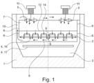
- Fig. 1 shows an embodiment being useful for understanding the invention, which is outside the subject-matter of the claims.
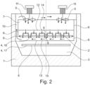
- Figure 2 shows an embodiment according to the present invention, which discloses an apparatus for cooling products according to claim 1.
- Fig. 1 shows a first embodiment of an apparatus 1 for cooling products 2 that comprises a cooling chamber 3 with a conveyor 4 for conveying the products 2 through the cooling chamber 3.
- the conveyor has a first run 16 and a second run 17.
- the products 2 can be received at a first side 8 of the conveyor.
- the conveyor 4 comprises a plurality of perforation openings and is designed such that a pressure gradient between the first side 8 of the conveyor 4 and a second side 9 of the conveyor 4 is generated when the first side 8 of the conveyor 4 is impinged with a cooling gas.
- the conveyor 4 is designed such that the cooling gas can penetrate through the conveyor 4 so as to have a second pressure at the second side 9 of the conveyor 4.
- the second pressure is lower than the first pressure.
- the first side 8 of the conveyor 4 is an upper side and the second side 9 of the conveyor 4 is a lower side.
- the apparatus 1 comprises two circulators 5 for circulating the cooling gas within the cooling chamber 3. Each circulator 5 has a motor 11. Further, the apparatus 1 comprises a first aperture element 12 with a plurality of first aperture openings 14.
- the conveyor 4 and the circulators 5 are arranged within the cooling chamber 3 such that the cooling gas can impinge a first side 8 of the conveyor 4.
- the first aperture element 12 is arranged within the cooling chamber 3 such that the cooling gas penetrates through the first aperture openings 14 before impinging the first side 8 of the conveyor 4.
- the first aperture openings 14 are slits oriented along a conveying direction of the conveyor 4.
- the conveying direction of the conveyor 4 is oriented perpendicular to the drawing plane of Fig. 1 .
- the apparatus 1 further comprises guiding elements 6 for guiding a flow of the cooling gas, wherein the guiding elements 6 are arranged within the cooling chamber 3 such that an impingement section 7 is formed adjacent to the first side 8 of the conveyor 4, in which the cooling gas can impinge the first side 8 of the conveyor 4 having a first pressure.
- the impingement section 7 has a rectangular cross section in a plane perpendicular to the conveying direction of the conveyor 4.
- the first aperture element 12 is arranged within the impingement section 7.
- the conveyor 4 is designed such that the cooling gas can penetrate through the conveyor 4 so as to have a second pressure at a second side 9 of the conveyor 4, wherein the second pressure is lower than the first pressure, and wherein the guiding elements 6 are arranged to form a backflow channel 10 from the second side 9 of the conveyor 4 to the circulators 5.
- the cooling gas can be directed into the impingement section 7 via the circulators 5.
- the guiding elements 6 are arranged such that the cooling gas can flow concurrently through the impingement section 7 and the backflow channel 10.
- the backflow channel 10 is confined by guiding elements 6 and a boundary of the cooling chamber 3.
- One of the guiding elements 6 is arranged between the circulators 5.
- the products 2 can be placed onto the conveyor 4 in such a way that each of the products 2 is assigned at least one respective of the first aperture openings 14.
- the first aperture opening 14 assigned to a product 2 is located above below the product 2.
- the cooling gas that penetrates through the at least one first aperture opening 14 assigned to a respective product 2 impinges the product 2 centrally.
- Fig. 1 In the cross section view of Fig. 1 two circulators 5 can be seen. Further circulators 5 can be provided at other positions in the conveying direction. Respective further guiding elements 6 may also be provided.
- Fig. 2 shows a second embodiment of an apparatus 1 for cooling products 2.
- the second embodiment is equivalent to the first embodiment.
- the second embodiment further comprises a second aperture element 13 with a plurality of second aperture openings 15.
- the second aperture element 13 is provided such that the cooling gas penetrates through the second aperture openings 15 after having passed through the conveyor 4.
- the second aperture openings 15 are slits oriented along a conveying direction of the conveyor 4.
- the first aperture element 12 and the second aperture element 13 are designed and arranged such that each of the first aperture openings 14 is aligned with a corresponding of the second aperture openings 15.
- products 2 such as food products can be cooled using a cooling gas such as a gas comprising nitrogen.
- a cooling gas such as a gas comprising nitrogen.
- aperture elements 12, 13 a flow of the cooling gas is guided.
- the products 2 can be cooled particularly energy efficiently and at a particularly high cooling rate.
Landscapes
- Engineering & Computer Science (AREA)
- Mechanical Engineering (AREA)
- Chemical & Material Sciences (AREA)
- Combustion & Propulsion (AREA)
- Physics & Mathematics (AREA)
- Thermal Sciences (AREA)
- General Engineering & Computer Science (AREA)
- Devices That Are Associated With Refrigeration Equipment (AREA)
Claims (14)
- Einrichtung (1) zum Kühlen von Produkten (2), die mindestens Folgendes umfasst:- eine Kühlkammer (3) mit einem Förderer (4) zum Fördern der Produkte (2) durch die Kühlkammer (3),- mindestens eine Umwälzvorrichtung (5) zum Umwälzen eines Kühlgases innerhalb zumindest eines Teils der Kühlkammer (3),- ein erstes Blendenelement (12) mit mehreren ersten Blendenöffnungen (14), wobei der Förderer (4) und die mindestens eine Umwälzvorrichtung (5) innerhalb der Kühlkammer (3) derart angeordnet sind, dass das Kühlgas auf eine erste Seite (8) des Förderers (4) aufprallen kann, dadurch gekennzeichnet, dass das erste Blendenelement (12) innerhalb der Kühlkammer (3) derart angeordnet ist, dass das Kühlgas durch die ersten Blendenöffnungen (14) dringt, bevor es auf die erste Seite (8) des Förderers (4) aufprallt, wobei ein zweites Blendenelement (13) mit mehreren zweiten Blendenöffnungen (15) derart bereitgestellt ist, dass das Kühlgas durch die zweiten Blendenöffnungen (15) dringt, nachdem es den Förderer (4) durchströmt hat.
- Einrichtung (1) nach Anspruch 1, wobei der Förderer (4) derart ausgestaltet ist, dass ein Druckgradient zwischen der ersten Seite (8) des Förderers (4) und der zweiten Seite (9) des Förderers (4) erzeugt wird, wenn Kühlgas auf die erste Seite (8) des Förderers (4) aufprallt.
- Einrichtung (1) nach einem der vorhergehenden Ansprüche, wobei die Einrichtung (1) derart ausgestaltet ist, dass die Produkte (2) an der ersten Seite (8) des Förderers (4) aufgenommen werden können.
- Einrichtung (1) nach einem der vorhergehenden Ansprüche, wobei die ersten Blendenöffnungen (14) Schlitze sind, die entlang einer Förderrichtung des Förderers (4) ausgerichtet sind.
- Einrichtung (1) nach einem der vorhergehenden Ansprüche, wobei die zweiten Blendenöffnungen (15) Schlitze sind, die entlang einer Förderrichtung des Förderers (4) ausgerichtet sind.
- Einrichtung (1) nach einem der vorhergehenden Ansprüche, wobei das erste Blendenelement (12) und das zweite Blendenelement (13) derart ausgestaltet und angeordnet sind, dass jede der ersten Blendenöffnungen (14) mit einer entsprechenden der zweiten Blendenöffnungen (15) ausgerichtet ist.
- Einrichtung (1) nach einem der vorhergehenden Ansprüche, wobei die Einrichtung (1) ferner Führungselemente (6) zum Führen einer Strömung des Kühlgases umfasst, wobei die Führungselemente (6) innerhalb der Kühlkammer (3) derart angeordnet sind, dass ein Aufprallabschnitt (7) angrenzend an eine erste Seite (8) des Förderers (4) ausgebildet wird, in dem das Kühlgas auf die erste Seite (8) des Förderers (4) aufprallen kann, die einen ersten Druck aufweist, wobei das erste Blendenelement (12) innerhalb des Aufprallabschnitts (7) angeordnet ist, wobei der Förderer (4) derart ausgestaltet ist, dass das Kühlgas durch den Förderer (4) dringen kann, so dass ein zweiter Druck an einer zweiten Seite (9) des Förderers (4) entsteht, wobei der zweite Druck niedriger als der erste Druck ist, und wobei die Führungselemente (6) derart angeordnet sind, dass sie mindestens einen Rückströmkanal (10) von der zweiten Seite (9) des Förderers (4) zu der mindestens einen Umwälzvorrichtung (5) ausbilden, und wobei das Kühlgas über die mindestens eine Umwälzvorrichtung (5) in den Aufprallabschnitt (7) geleitet werden kann.
- Einrichtung (1) nach Anspruch 7, wobei die Führungselemente (6) derart angeordnet sind, dass das Kühlgas gleichzeitig durch den Aufprallabschnitt (7) und den mindestens einen Rückströmkanal (10) strömen kann.
- Einrichtung (1) nach Anspruch 7 oder 8, wobei mindestens zwei Umwälzvorrichtungen (5) vorgesehen sind und wobei mindestens eines der Führungselemente (6) zwischen den Umwälzvorrichtungen (5) angeordnet ist.
- Einrichtung (1) nach einem der Ansprüche 7 bis 9, wobei der mindestens eine Rückströmkanal (10) zwischen mindestens einem jeweiligen Führungselement (6) und einer Begrenzung der Kühlkammer (3) ausgebildet ist.
- Einrichtung (1) nach einem der vorhergehenden Ansprüche, wobei der Aufprallabschnitt (7) einen rechteckigen Querschnitt senkrecht zu einer Förderrichtung des Förderers (4) aufweist.
- Verfahren zum Kühlen von Produkten, das mindestens die folgenden Schritte umfasst:a) Fördern der Produkte (2) durch eine Kühlkammer (3) mit einem Förderer (4), undb) Erzeugen einer Kühlgasströmung innerhalb der Kühlkammer (3), wobei die Strömung derart erzeugt wird, dass das Kühlgas auf eine erste Seite (8) des Förderers (4) aufprallt, nachdem es durch erste Blendenöffnungen (14) eines ersten Blendenelements (12) gedrungen ist, und dass das Kühlgas durch zweite Blendenöffnungen (15) eines zweiten Blendenelements (13) dringt, nachdem es den Förderer (4) durchströmt hat.
- Verfahren nach Anspruch 12, wobei die Produkte (2) derart auf dem Förderer (4) platziert werden, dass jedem der Produkte (2) jeweils mindestens eine der ersten Blendenöffnungen (14) zugeordnet wird.
- Verfahren nach Anspruch 13, wobei das Kühlgas, das durch die mindestens eine erste Blendenöffnung (14) dringt, die einem jeweiligen Produkt (2) zugeordnet ist, mittig auf das Produkt (2) aufprallt.
Priority Applications (3)
| Application Number | Priority Date | Filing Date | Title |
|---|---|---|---|
| ES17208688T ES3031300T3 (en) | 2017-12-19 | 2017-12-19 | Apparatus and method for cooling products |
| EP17208688.6A EP3502595B1 (de) | 2017-12-19 | 2017-12-19 | Vorrichtung und verfahren zur kühlung von produkten |
| US16/225,632 US20190186804A1 (en) | 2017-12-19 | 2018-12-19 | Apparatus and method for cooling products |
Applications Claiming Priority (1)
| Application Number | Priority Date | Filing Date | Title |
|---|---|---|---|
| EP17208688.6A EP3502595B1 (de) | 2017-12-19 | 2017-12-19 | Vorrichtung und verfahren zur kühlung von produkten |
Publications (2)
| Publication Number | Publication Date |
|---|---|
| EP3502595A1 EP3502595A1 (de) | 2019-06-26 |
| EP3502595B1 true EP3502595B1 (de) | 2025-04-23 |
Family
ID=60781760
Family Applications (1)
| Application Number | Title | Priority Date | Filing Date |
|---|---|---|---|
| EP17208688.6A Active EP3502595B1 (de) | 2017-12-19 | 2017-12-19 | Vorrichtung und verfahren zur kühlung von produkten |
Country Status (3)
| Country | Link |
|---|---|
| US (1) | US20190186804A1 (de) |
| EP (1) | EP3502595B1 (de) |
| ES (1) | ES3031300T3 (de) |
Families Citing this family (1)
| Publication number | Priority date | Publication date | Assignee | Title |
|---|---|---|---|---|
| CN111351298B (zh) * | 2020-03-10 | 2021-12-14 | 泉州台商投资区茂源工业设计有限公司 | 一种数控机床零部件生产的冷却定型输送装置 |
Citations (1)
| Publication number | Priority date | Publication date | Assignee | Title |
|---|---|---|---|---|
| US20180058744A1 (en) * | 2016-09-01 | 2018-03-01 | Michael D. Newman | Method and apparatus for impingement freezing of irregularly shaped products |
Family Cites Families (7)
| Publication number | Priority date | Publication date | Assignee | Title |
|---|---|---|---|---|
| US1865168A (en) * | 1930-03-25 | 1932-06-28 | Equity Construction Company In | Refrigerating method and apparatus |
| US4481782A (en) * | 1983-01-25 | 1984-11-13 | The Boc Group, Inc. | Methods and apparatus for refrigerating products |
| JPS63259366A (ja) * | 1987-04-14 | 1988-10-26 | 株式会社 前川製作所 | ジエツト気流による冷凍、加熱または乾燥等の伝熱促進方法 |
| WO2004018945A2 (en) * | 2002-08-20 | 2004-03-04 | The Boc Group, Inc. | Flow enhanced tunnel freezer |
| DK200500335A (da) * | 2005-03-04 | 2006-09-05 | Carnitech As | Impingement fryser |
| US20070062380A1 (en) * | 2005-08-03 | 2007-03-22 | The Boc Group, Inc. | Crust freezing system |
| DE102008019903A1 (de) * | 2008-04-21 | 2009-10-22 | Airinotec Gmbh | Kühltunnel und Verfahren zum Betrieb eines solchen |
-
2017
- 2017-12-19 ES ES17208688T patent/ES3031300T3/es active Active
- 2017-12-19 EP EP17208688.6A patent/EP3502595B1/de active Active
-
2018
- 2018-12-19 US US16/225,632 patent/US20190186804A1/en not_active Abandoned
Patent Citations (1)
| Publication number | Priority date | Publication date | Assignee | Title |
|---|---|---|---|---|
| US20180058744A1 (en) * | 2016-09-01 | 2018-03-01 | Michael D. Newman | Method and apparatus for impingement freezing of irregularly shaped products |
Also Published As
| Publication number | Publication date |
|---|---|
| ES3031300T3 (en) | 2025-07-07 |
| US20190186804A1 (en) | 2019-06-20 |
| EP3502595A1 (de) | 2019-06-26 |
Similar Documents
| Publication | Publication Date | Title |
|---|---|---|
| EP1543276B1 (de) | Tunnelgefrieranlage mit verbesserter Strömung | |
| US9739520B2 (en) | Combined impingement/plate freezer | |
| JP3671121B2 (ja) | 衝突冷却装置 | |
| KR101693634B1 (ko) | 냉기 분사 기구 | |
| CN109421961B (zh) | 收缩装置和用于从收缩装置的内部空间中抽吸空气的方法 | |
| EP3502595B1 (de) | Vorrichtung und verfahren zur kühlung von produkten | |
| EP3290834B1 (de) | Impinger zum kühlen oder gefrieren von produkten und zugehöriges verfahren | |
| EP3502596B1 (de) | Vorrichtung und verfahren zur kühlung von produkten | |
| US9791201B1 (en) | Spiral chiller apparatus and method of chilling | |
| EP3502594A1 (de) | Vorrichtung und verfahren zur kühlung von produkten | |
| EP3216352B1 (de) | Kühlvorrichtung und verfahren zum kühlen von rieselfähigen elementen | |
| JP2987590B1 (ja) | 多段式凍結装置及び方法 | |
| JP7061847B2 (ja) | 食品冷凍装置および食品冷凍方法 | |
| US20100162727A1 (en) | Freezer with pulse flow generator | |
| US20070214679A1 (en) | Thermal impingement apparatus | |
| JP6146799B2 (ja) | 蒸気加熱庫内の蒸気温度の調整構造 | |
| AU2017312447B2 (en) | Mechanical snow and ice removal for impinger | |
| NL1008720C2 (nl) | Inrichting en werkwijze voor het invriezen van voedselproducten. | |
| EP3444547B1 (de) | Lebensmittelgefrieranlage und zugehöriges verfahren zur abfuhr von gefriergas | |
| US20060046222A1 (en) | Apparatus for uniform flow distribution of gas in processing equipment | |
| EP3318825B1 (de) | Verfahren und vorrichtung zum kühlen von gegenständen mittels einer kryogenen flüssigkeit mittels oszillierenden fluidseparationsdüsen | |
| WO2024263949A1 (en) | Appartus and methods of providing uniform surface freezing to food products | |
| EP3764030A1 (de) | Verfahren und vorrichtung zur kühlung von produkten | |
| EP3395183A1 (de) | Kühlungsvorrichtung zum kühlen fliessfähiger artikel und verwendung davon | |
| NZ748106B2 (en) | Mechanical snow and ice removal for impinger |
Legal Events
| Date | Code | Title | Description |
|---|---|---|---|
| PUAI | Public reference made under article 153(3) epc to a published international application that has entered the european phase |
Free format text: ORIGINAL CODE: 0009012 |
|
| STAA | Information on the status of an ep patent application or granted ep patent |
Free format text: STATUS: THE APPLICATION HAS BEEN PUBLISHED |
|
| AK | Designated contracting states |
Kind code of ref document: A1 Designated state(s): AL AT BE BG CH CY CZ DE DK EE ES FI FR GB GR HR HU IE IS IT LI LT LU LV MC MK MT NL NO PL PT RO RS SE SI SK SM TR |
|
| AX | Request for extension of the european patent |
Extension state: BA ME |
|
| STAA | Information on the status of an ep patent application or granted ep patent |
Free format text: STATUS: REQUEST FOR EXAMINATION WAS MADE |
|
| 17P | Request for examination filed |
Effective date: 20191219 |
|
| RBV | Designated contracting states (corrected) |
Designated state(s): AL AT BE BG CH CY CZ DE DK EE ES FI FR GB GR HR HU IE IS IT LI LT LU LV MC MK MT NL NO PL PT RO RS SE SI SK SM TR |
|
| STAA | Information on the status of an ep patent application or granted ep patent |
Free format text: STATUS: EXAMINATION IS IN PROGRESS |
|
| 17Q | First examination report despatched |
Effective date: 20210216 |
|
| RAP3 | Party data changed (applicant data changed or rights of an application transferred) |
Owner name: L'AIR LIQUIDE, SOCIETE ANONYME POUR L'ETUDE ET L'EXPLOITATION DES PROCEDES GEORGES CLAUDE Owner name: AIR LIQUIDE DEUTSCHLAND GMBH |
|
| GRAP | Despatch of communication of intention to grant a patent |
Free format text: ORIGINAL CODE: EPIDOSNIGR1 |
|
| STAA | Information on the status of an ep patent application or granted ep patent |
Free format text: STATUS: GRANT OF PATENT IS INTENDED |
|
| RIC1 | Information provided on ipc code assigned before grant |
Ipc: F25D 3/11 20060101ALN20241023BHEP Ipc: F25D 13/06 20060101AFI20241023BHEP |
|
| INTG | Intention to grant announced |
Effective date: 20241108 |
|
| GRAJ | Information related to disapproval of communication of intention to grant by the applicant or resumption of examination proceedings by the epo deleted |
Free format text: ORIGINAL CODE: EPIDOSDIGR1 |
|
| STAA | Information on the status of an ep patent application or granted ep patent |
Free format text: STATUS: EXAMINATION IS IN PROGRESS |
|
| GRAP | Despatch of communication of intention to grant a patent |
Free format text: ORIGINAL CODE: EPIDOSNIGR1 |
|
| STAA | Information on the status of an ep patent application or granted ep patent |
Free format text: STATUS: GRANT OF PATENT IS INTENDED |
|
| INTC | Intention to grant announced (deleted) | ||
| RIC1 | Information provided on ipc code assigned before grant |
Ipc: F25D 3/11 20060101ALN20250116BHEP Ipc: F25D 13/06 20060101AFI20250116BHEP |
|
| INTG | Intention to grant announced |
Effective date: 20250124 |
|
| GRAS | Grant fee paid |
Free format text: ORIGINAL CODE: EPIDOSNIGR3 |
|
| GRAA | (expected) grant |
Free format text: ORIGINAL CODE: 0009210 |
|
| STAA | Information on the status of an ep patent application or granted ep patent |
Free format text: STATUS: THE PATENT HAS BEEN GRANTED |
|
| AK | Designated contracting states |
Kind code of ref document: B1 Designated state(s): AL AT BE BG CH CY CZ DE DK EE ES FI FR GB GR HR HU IE IS IT LI LT LU LV MC MK MT NL NO PL PT RO RS SE SI SK SM TR |
|
| REG | Reference to a national code |
Ref country code: GB Ref legal event code: FG4D |
|
| REG | Reference to a national code |
Ref country code: CH Ref legal event code: EP |
|
| REG | Reference to a national code |
Ref country code: DE Ref legal event code: R096 Ref document number: 602017089032 Country of ref document: DE |
|
| REG | Reference to a national code |
Ref country code: IE Ref legal event code: FG4D |
|
| REG | Reference to a national code |
Ref country code: NL Ref legal event code: FP |
|
| REG | Reference to a national code |
Ref country code: ES Ref legal event code: FG2A Ref document number: 3031300 Country of ref document: ES Kind code of ref document: T3 Effective date: 20250707 |
|
| RAP4 | Party data changed (patent owner data changed or rights of a patent transferred) |
Owner name: AIR LIQUIDE DEUTSCHLAND GMBH Owner name: L'AIR LIQUIDE, SOCIETE ANONYME POUR L'ETUDEET L'EXPLOITATION DES PROCEDES GEORGES CLAUDE |
|
| REG | Reference to a national code |
Ref country code: DE Ref legal event code: R081 Ref document number: 602017089032 Country of ref document: DE Owner name: AIR LIQUIDE DEUTSCHLAND GMBH, DE Free format text: FORMER OWNER: AIR LIQUIDE DEUTSCHLAND GMBH, 40235 DUESSELDORF, DE |
|
| REG | Reference to a national code |
Ref country code: AT Ref legal event code: MK05 Ref document number: 1788100 Country of ref document: AT Kind code of ref document: T Effective date: 20250423 |
|
| PG25 | Lapsed in a contracting state [announced via postgrant information from national office to epo] |
Ref country code: PT Free format text: LAPSE BECAUSE OF FAILURE TO SUBMIT A TRANSLATION OF THE DESCRIPTION OR TO PAY THE FEE WITHIN THE PRESCRIBED TIME-LIMIT Effective date: 20250825 Ref country code: FI Free format text: LAPSE BECAUSE OF FAILURE TO SUBMIT A TRANSLATION OF THE DESCRIPTION OR TO PAY THE FEE WITHIN THE PRESCRIBED TIME-LIMIT Effective date: 20250423 |
|
| REG | Reference to a national code |
Ref country code: LT Ref legal event code: MG9D |
|
| PG25 | Lapsed in a contracting state [announced via postgrant information from national office to epo] |
Ref country code: GR Free format text: LAPSE BECAUSE OF FAILURE TO SUBMIT A TRANSLATION OF THE DESCRIPTION OR TO PAY THE FEE WITHIN THE PRESCRIBED TIME-LIMIT Effective date: 20250724 Ref country code: NO Free format text: LAPSE BECAUSE OF FAILURE TO SUBMIT A TRANSLATION OF THE DESCRIPTION OR TO PAY THE FEE WITHIN THE PRESCRIBED TIME-LIMIT Effective date: 20250723 |
|
| PG25 | Lapsed in a contracting state [announced via postgrant information from national office to epo] |
Ref country code: PL Free format text: LAPSE BECAUSE OF FAILURE TO SUBMIT A TRANSLATION OF THE DESCRIPTION OR TO PAY THE FEE WITHIN THE PRESCRIBED TIME-LIMIT Effective date: 20250423 |
|
| PG25 | Lapsed in a contracting state [announced via postgrant information from national office to epo] |
Ref country code: BG Free format text: LAPSE BECAUSE OF FAILURE TO SUBMIT A TRANSLATION OF THE DESCRIPTION OR TO PAY THE FEE WITHIN THE PRESCRIBED TIME-LIMIT Effective date: 20250423 |
|
| PG25 | Lapsed in a contracting state [announced via postgrant information from national office to epo] |
Ref country code: HR Free format text: LAPSE BECAUSE OF FAILURE TO SUBMIT A TRANSLATION OF THE DESCRIPTION OR TO PAY THE FEE WITHIN THE PRESCRIBED TIME-LIMIT Effective date: 20250423 |
|
| PG25 | Lapsed in a contracting state [announced via postgrant information from national office to epo] |
Ref country code: AT Free format text: LAPSE BECAUSE OF FAILURE TO SUBMIT A TRANSLATION OF THE DESCRIPTION OR TO PAY THE FEE WITHIN THE PRESCRIBED TIME-LIMIT Effective date: 20250423 |
|
| PG25 | Lapsed in a contracting state [announced via postgrant information from national office to epo] |
Ref country code: RS Free format text: LAPSE BECAUSE OF FAILURE TO SUBMIT A TRANSLATION OF THE DESCRIPTION OR TO PAY THE FEE WITHIN THE PRESCRIBED TIME-LIMIT Effective date: 20250723 |
|
| PG25 | Lapsed in a contracting state [announced via postgrant information from national office to epo] |
Ref country code: IS Free format text: LAPSE BECAUSE OF FAILURE TO SUBMIT A TRANSLATION OF THE DESCRIPTION OR TO PAY THE FEE WITHIN THE PRESCRIBED TIME-LIMIT Effective date: 20250823 |
|
| PG25 | Lapsed in a contracting state [announced via postgrant information from national office to epo] |
Ref country code: LV Free format text: LAPSE BECAUSE OF FAILURE TO SUBMIT A TRANSLATION OF THE DESCRIPTION OR TO PAY THE FEE WITHIN THE PRESCRIBED TIME-LIMIT Effective date: 20250423 |
|
| PGFP | Annual fee paid to national office [announced via postgrant information from national office to epo] |
Ref country code: DE Payment date: 20251211 Year of fee payment: 9 |
|
| PG25 | Lapsed in a contracting state [announced via postgrant information from national office to epo] |
Ref country code: SM Free format text: LAPSE BECAUSE OF FAILURE TO SUBMIT A TRANSLATION OF THE DESCRIPTION OR TO PAY THE FEE WITHIN THE PRESCRIBED TIME-LIMIT Effective date: 20250423 Ref country code: DK Free format text: LAPSE BECAUSE OF FAILURE TO SUBMIT A TRANSLATION OF THE DESCRIPTION OR TO PAY THE FEE WITHIN THE PRESCRIBED TIME-LIMIT Effective date: 20250423 |
|
| PGFP | Annual fee paid to national office [announced via postgrant information from national office to epo] |
Ref country code: IT Payment date: 20251222 Year of fee payment: 9 |
|
| PGFP | Annual fee paid to national office [announced via postgrant information from national office to epo] |
Ref country code: FR Payment date: 20251229 Year of fee payment: 9 Ref country code: NL Payment date: 20251219 Year of fee payment: 9 |
|
| PGFP | Annual fee paid to national office [announced via postgrant information from national office to epo] |
Ref country code: BE Payment date: 20251219 Year of fee payment: 9 |
|
| PG25 | Lapsed in a contracting state [announced via postgrant information from national office to epo] |
Ref country code: CZ Free format text: LAPSE BECAUSE OF FAILURE TO SUBMIT A TRANSLATION OF THE DESCRIPTION OR TO PAY THE FEE WITHIN THE PRESCRIBED TIME-LIMIT Effective date: 20250423 |
|
| PG25 | Lapsed in a contracting state [announced via postgrant information from national office to epo] |
Ref country code: EE Free format text: LAPSE BECAUSE OF FAILURE TO SUBMIT A TRANSLATION OF THE DESCRIPTION OR TO PAY THE FEE WITHIN THE PRESCRIBED TIME-LIMIT Effective date: 20250423 |
|
| REG | Reference to a national code |
Ref country code: DE Ref legal event code: R097 Ref document number: 602017089032 Country of ref document: DE |
|
| PG25 | Lapsed in a contracting state [announced via postgrant information from national office to epo] |
Ref country code: RO Free format text: LAPSE BECAUSE OF FAILURE TO SUBMIT A TRANSLATION OF THE DESCRIPTION OR TO PAY THE FEE WITHIN THE PRESCRIBED TIME-LIMIT Effective date: 20250423 Ref country code: SK Free format text: LAPSE BECAUSE OF FAILURE TO SUBMIT A TRANSLATION OF THE DESCRIPTION OR TO PAY THE FEE WITHIN THE PRESCRIBED TIME-LIMIT Effective date: 20250423 |
|
| PLBE | No opposition filed within time limit |
Free format text: ORIGINAL CODE: 0009261 |
|
| STAA | Information on the status of an ep patent application or granted ep patent |
Free format text: STATUS: NO OPPOSITION FILED WITHIN TIME LIMIT |
|
| REG | Reference to a national code |
Ref country code: CH Ref legal event code: L10 Free format text: ST27 STATUS EVENT CODE: U-0-0-L10-L00 (AS PROVIDED BY THE NATIONAL OFFICE) Effective date: 20260304 |