EP3502427A1 - Séparateur d'huile comprenant des éléments en spirale délimitant des trajets d'écoulement hélicoïdaux - Google Patents
Séparateur d'huile comprenant des éléments en spirale délimitant des trajets d'écoulement hélicoïdaux Download PDFInfo
- Publication number
- EP3502427A1 EP3502427A1 EP18214132.5A EP18214132A EP3502427A1 EP 3502427 A1 EP3502427 A1 EP 3502427A1 EP 18214132 A EP18214132 A EP 18214132A EP 3502427 A1 EP3502427 A1 EP 3502427A1
- Authority
- EP
- European Patent Office
- Prior art keywords
- oil
- oil separator
- inlet
- extending
- valve head
- Prior art date
- Legal status (The legal status is an assumption and is not a legal conclusion. Google has not performed a legal analysis and makes no representation as to the accuracy of the status listed.)
- Granted
Links
- 239000007789 gas Substances 0.000 claims abstract description 120
- 230000004044 response Effects 0.000 claims abstract description 13
- 239000011295 pitch Substances 0.000 claims description 17
- 230000002093 peripheral effect Effects 0.000 claims description 15
- 230000033001 locomotion Effects 0.000 claims description 6
- 230000010006 flight Effects 0.000 claims description 5
- 238000005192 partition Methods 0.000 description 16
- 238000002485 combustion reaction Methods 0.000 description 14
- 239000000463 material Substances 0.000 description 13
- 239000003595 mist Substances 0.000 description 13
- 238000011144 upstream manufacturing Methods 0.000 description 10
- 238000000926 separation method Methods 0.000 description 7
- 238000007373 indentation Methods 0.000 description 5
- 230000005484 gravity Effects 0.000 description 4
- 230000001133 acceleration Effects 0.000 description 3
- 238000000034 method Methods 0.000 description 3
- 239000002245 particle Substances 0.000 description 3
- 238000005057 refrigeration Methods 0.000 description 3
- 239000004677 Nylon Substances 0.000 description 2
- 239000000446 fuel Substances 0.000 description 2
- 239000007788 liquid Substances 0.000 description 2
- 238000004519 manufacturing process Methods 0.000 description 2
- 239000000203 mixture Substances 0.000 description 2
- 229920001778 nylon Polymers 0.000 description 2
- 238000003466 welding Methods 0.000 description 2
- 241000251468 Actinopterygii Species 0.000 description 1
- 239000002253 acid Substances 0.000 description 1
- 150000007513 acids Chemical class 0.000 description 1
- 238000004026 adhesive bonding Methods 0.000 description 1
- 238000005452 bending Methods 0.000 description 1
- 239000006227 byproduct Substances 0.000 description 1
- 239000000567 combustion gas Substances 0.000 description 1
- 230000000295 complement effect Effects 0.000 description 1
- 238000010276 construction Methods 0.000 description 1
- 230000007423 decrease Effects 0.000 description 1
- 238000005516 engineering process Methods 0.000 description 1
- 230000013011 mating Effects 0.000 description 1
- 230000007246 mechanism Effects 0.000 description 1
- 238000012986 modification Methods 0.000 description 1
- 230000004048 modification Effects 0.000 description 1
- 238000000465 moulding Methods 0.000 description 1
- 230000008569 process Effects 0.000 description 1
- 230000001105 regulatory effect Effects 0.000 description 1
- 238000009423 ventilation Methods 0.000 description 1
Images


Classifications
-
- F—MECHANICAL ENGINEERING; LIGHTING; HEATING; WEAPONS; BLASTING
- F01—MACHINES OR ENGINES IN GENERAL; ENGINE PLANTS IN GENERAL; STEAM ENGINES
- F01M—LUBRICATING OF MACHINES OR ENGINES IN GENERAL; LUBRICATING INTERNAL COMBUSTION ENGINES; CRANKCASE VENTILATING
- F01M13/00—Crankcase ventilating or breathing
- F01M13/04—Crankcase ventilating or breathing having means for purifying air before leaving crankcase, e.g. removing oil
-
- B—PERFORMING OPERATIONS; TRANSPORTING
- B01—PHYSICAL OR CHEMICAL PROCESSES OR APPARATUS IN GENERAL
- B01D—SEPARATION
- B01D45/00—Separating dispersed particles from gases or vapours by gravity, inertia, or centrifugal forces
- B01D45/04—Separating dispersed particles from gases or vapours by gravity, inertia, or centrifugal forces by utilising inertia
- B01D45/08—Separating dispersed particles from gases or vapours by gravity, inertia, or centrifugal forces by utilising inertia by impingement against baffle separators
-
- F—MECHANICAL ENGINEERING; LIGHTING; HEATING; WEAPONS; BLASTING
- F01—MACHINES OR ENGINES IN GENERAL; ENGINE PLANTS IN GENERAL; STEAM ENGINES
- F01M—LUBRICATING OF MACHINES OR ENGINES IN GENERAL; LUBRICATING INTERNAL COMBUSTION ENGINES; CRANKCASE VENTILATING
- F01M13/00—Crankcase ventilating or breathing
- F01M13/0011—Breather valves
-
- F—MECHANICAL ENGINEERING; LIGHTING; HEATING; WEAPONS; BLASTING
- F01—MACHINES OR ENGINES IN GENERAL; ENGINE PLANTS IN GENERAL; STEAM ENGINES
- F01M—LUBRICATING OF MACHINES OR ENGINES IN GENERAL; LUBRICATING INTERNAL COMBUSTION ENGINES; CRANKCASE VENTILATING
- F01M13/00—Crankcase ventilating or breathing
- F01M2013/0038—Layout of crankcase breathing systems
- F01M2013/0044—Layout of crankcase breathing systems with one or more valves
-
- F—MECHANICAL ENGINEERING; LIGHTING; HEATING; WEAPONS; BLASTING
- F01—MACHINES OR ENGINES IN GENERAL; ENGINE PLANTS IN GENERAL; STEAM ENGINES
- F01M—LUBRICATING OF MACHINES OR ENGINES IN GENERAL; LUBRICATING INTERNAL COMBUSTION ENGINES; CRANKCASE VENTILATING
- F01M13/00—Crankcase ventilating or breathing
- F01M13/04—Crankcase ventilating or breathing having means for purifying air before leaving crankcase, e.g. removing oil
- F01M2013/0422—Separating oil and gas with a centrifuge device
- F01M2013/0427—Separating oil and gas with a centrifuge device the centrifuge device having no rotating part, e.g. cyclone
-
- F—MECHANICAL ENGINEERING; LIGHTING; HEATING; WEAPONS; BLASTING
- F01—MACHINES OR ENGINES IN GENERAL; ENGINE PLANTS IN GENERAL; STEAM ENGINES
- F01M—LUBRICATING OF MACHINES OR ENGINES IN GENERAL; LUBRICATING INTERNAL COMBUSTION ENGINES; CRANKCASE VENTILATING
- F01M13/00—Crankcase ventilating or breathing
- F01M13/04—Crankcase ventilating or breathing having means for purifying air before leaving crankcase, e.g. removing oil
- F01M2013/0461—Crankcase ventilating or breathing having means for purifying air before leaving crankcase, e.g. removing oil with a labyrinth
Definitions
- the present disclosure relates generally to oil separators for separating oil from oil-laden gases. More particularly, the present disclosure relates to an oil separator that includes a plurality of spiral members that each define a helical flow path for guiding the oil-laden gases therethrough to separate oil from the oil-laden gases.
- Internal combustion engines of vehicles typically include a combustion chamber where a fuel/air mixture is burned to cause movement of a set of reciprocating pistons, as well as a crankcase which contains the crankshaft driven by the pistons.
- a combustion chamber where a fuel/air mixture is burned to cause movement of a set of reciprocating pistons, as well as a crankcase which contains the crankshaft driven by the pistons.
- combustion gases leak past the pistons from the combustion chamber and into the crankcase or cam shaft housing.
- These combustion or blowby gases typically contain by-products of the combustion process including moisture, acids and an oil mist. Oil mist can further be generated as the result of moving components in the crankcase sloshing hot oil around. It is known for the oil mist to be carried by a crankcase ventilation system to the intake manifold of the internal combustion engine where it is then burned in the combustion chamber along with the fuel/air mixture. This often results in an undesirable increase in oil consumption.
- the oil separator includes a housing that defines a chamber.
- a partition assembly is disposed in the chamber and divides the chamber into an entry segment and an exit segment.
- the entry segment defines an inlet that extends into the chamber for receiving oil-laden gases from the crankcase, and the exit segment defines an outlet that extends into the chamber for expelling gases to the intake manifold.
- the partition assembly includes a channel that extends between a first opening in the entry segment and a second opening in the exit segment for passing the oil-laden gases between the entry and exit segments.
- a spiral member is disposed in the channel.
- the spiral member defines a helical flow path for guiding the oil-laden gases during passing of the oil-laden gases through the channel to separate the oil from the oil-laden gases. More specifically, small oil droplets pass and coalesce into larger droplets on the inner wall of the channel due to centrifugal forces created as the oil-laden gases pass through the helical flow path. The larger droplets are then directed by gravity to oil outlets and passed to a sump, which generally holds excess oil in the system.
- the flow rate of the crankcase gas inside the helical flow path depends on the quantity of crankcase gas produced per unit time and on the flow cross-section of the flow path.
- the quantity of crankcase gas produced per unit time is largely related to the speed and load of the engine.
- an oil separator for separating oil from oil-laden gases, the oil separator includes a housing having a plurality of cavities, with each of the cavities extending between a proximal end and a distal end.
- a plurality of augers each has a helical flight extending about a longitudinal central axis between an inlet end and an outlet end. The augers being disposed in separate ones of the cavities to form helical flow paths about the central longitudinal axes.
- At least one of the augers has an annular wall extending from the inlet end about the central longitudinal axis to bound an inlet chamber.
- An end cap having an inlet, is fixed to the annular wall over the inlet chamber.
- a plunger valve has a valve head disposed in the inlet chamber, wherein a spring member is configured to bias the valve head into a closed position in sealed abutment with the end cap to perfect a seal over the inlet to inhibit the flow of oil-laden gases therethrough.
- the valve head is moveable within the chamber against the bias of the spring member to an open position away from the end cap in response to pressure being applied against the valve head sufficient to overcome the bias of the spring member.
- the end cap can be provided with a through opening extending along the longitudinal central axis and the plunger valve can be provided with a valve stem extending from the valve head through the through opening, and wherein the spring member can be disposed about the valve stem.
- the end cap can be provided with an annular outer periphery extending between upper and lower walls, with the through opening extending through the upper and lower walls and the inlet extending into the outer periphery and through the lower wall.
- the valve stem can be provided having at least a portion with a non-circular outer peripheral surface, as viewed in cross-section taken transversely to the longitudinal central axis, with the through opening in the upper wall having a peripheral surface conforming at least in part with the non-circular outer peripheral surface of the valve stem to inhibit lateral play of the valve stem within the through opening in the upper wall.
- the through opening in the lower wall has an enlarged peripheral surface relative to the valve stem to form the portion of the inlet extending through the lower wall between the valve stem and the enlarged peripheral surface of the through opening.
- At least some of the helical flights can be provided having different helical pitches from one another to maximize the separating efficiency during varying flow rates.
- At least one of the plurality of augers does not have a valve head disposed therein, wherein the at least one auger having a valve head disposed in the inlet chamber has a helical flight with a first helical pitch and the at least one auger not having a plunger head disposed therein has a helical flight with a second helical pitch, with the first helical pitch being greater than the second helical pitch.
- the augers can be provided having one of a protrusion or a recess and the cavities can be provided having the other of a protrusion or a recess, with the protrusion and the recess being configured for a snap fit with one another to facilitate modular assembly.
- the protrusion can be formed as an annular rib and the recess can be formed as an annular groove.
- a protrusion can be provided to extend radially inwardly from the annular wall, with the protrusion forming a stop surface configured to confront the valve head to limit the movement of the valve head within the inlet chamber.
- each of the cavities can be configured the same for interchangeable receipt of any one of the plurality of augers to facilitate modular assembly.
- an oil separator for separating oil from oil-laden gases includes a housing having at least one cavity.
- An auger is disposed in at least one cavity, with the auger having a helical flight extending about a longitudinal central axis between an inlet end and an outlet end to form a helical flow path about the longitudinal central axis.
- At least one auger has an annular wall extending from the inlet end about the longitudinal central axis with an end wall fixed to the annular wall to bound an inlet chamber.
- the end wall includes an inlet extending into the inlet chamber to selectively allow the flow of oil-laden gases therethrough.
- a valve head is disposed in the inlet chamber and a spring member is configured to bias the valve head into a closed position to perfect a seal over the inlet to inhibit the flow of oil-laden gases therethrough.
- the valve head is moveable within the inlet chamber against the bias of the spring member to an open position in response to pressure being applied against the valve head sufficient to overcome the bias of the spring member.
- Example embodiments will now be described more fully with reference to the accompanying drawings.
- Each of the example embodiments is directed to an oil separator for separating oil from oil-laden gases.
- the example embodiments only are provided so that this disclosure will be thorough, and will fully convey the scope to those who are skilled in the art. Numerous specific details are set forth such as examples of specific components, devices, and methods, to provide a thorough understanding of embodiments of the present disclosure. It will be apparent to those skilled in the art that specific details need not be employed, that example embodiments may be embodied in many different forms and that neither should be construed to limit the scope of the disclosure. In some example embodiments, well-known processes, well-known device structures, and well-known technologies are not described in detail.
- the present disclosure is directed to one or more embodiments of an oil separator of the type well-suited for separating oil from oil-laden gases.
- the oil separator may be utilized to separate oil from gases of various devices such as, but not limited to, internal combustion engines of motor vehicles and refrigeration systems.
- the oil separator in accordance with one aspect of the present disclosure includes a housing defining a chamber.
- a partition assembly is disposed in the chamber and divides the chamber into an entry segment and an exit segment.
- the entry segment defines an inlet that extends into the chamber for receiving oil-laden gases, and the exit segment defines an outlet that extends into the chamber for expelling gases.
- the partition assembly includes a plurality of channels that each extend between a first opening in the entry segment and a second opening in the exit segment for passing the oil-laden gases between the entry and exit segments.
- a plurality of spiral members are each disposed in one of the channels. Each of the spiral members define a helical flow path for guiding the oil-laden gases in the helical flow path about the spiral member during passing of the oil-laden gases through the channels to separate the oil from the oil-laden gases.
- At least one valve can be connected to at least one of the openings of the channels.
- the stated valve is moveable between an open and closed position in response to a predetermined pressure being applied against the valve for maintaining the velocity of the oil-laden gases passing through the channels within a predetermined range.
- the oil separator further includes a fine mist separator assembly that includes a fibrous pad disposed in the exit chamber adjacent to and in alignment with the second openings for absorbing oil in the oil-laden gases immediately after the oil-laden gases have passed through the frames.
- an exemplary embodiment of an oil separator 20 is generally shown.
- the exemplary embodiment of the oil separator 20 is described in operable connection with an internal combustion engine of a vehicle, however, it should be appreciated that the oil separator 20 could also be connected to other systems, e.g., a refrigeration system.
- the oil separator 20 includes a housing 22 that has a base 24, a top 26 and a pair of sidewalls 28 and defines a chamber 30, 32.
- a partition assembly 34 is disposed in the chamber 30, 32 and divides the housing 22 into an entry segment 30 and an exit segment 32.
- the entry segment 30 defines an inlet 36 that extends into the chamber 30, 32 for receiving oil-laden gases from the crank-case of the combustion engine into the chamber 30, 32.
- the exit segment 32 defines a gas outlet 38 that extends into the chamber 30, 32 for expelling gases from the chamber 30, 32 to an air intake assembly of the combustion engine.
- a plurality of baffles 40 are disposed in the chamber 30, 32 in the entry segment 30 between the inlet 36 and the partition assembly 34.
- Each of the baffles 40 extend between the base 24 and the top 26 to define a labyrinth passage for guiding the oil-laden gases after the oil-laden gases have entered the chamber 30, 32 through the inlet 36.
- the baffles 40 separate the oil from the oil-laden gases during contact of the oil-laden gases with the baffles 40.
- At least one of the plurality of baffles 40 can be a "fish hook" style baffle that extends from the sidewall 28 in an arc shape over the inlet 36 which is particularly utilized to isolate splashing liquid oil that may be present during immediate entry of the oil-laden gases through the inlet 36.
- At least one of the plurality of baffles 40 extends linearly from the sidewall 28. It should be appreciated that the shapes and positions of the baffles 40 provide for a swirling shape of the oil-laden gases passing through the labyrinth passage which aids in causing contact between oil particles and the baffles 40.
- the base 24 of the housing 22 defines at least one oil outlet 44 in the chamber 30, 32 for expelling the oil that has been separated from the oil-laden gases of the crank-case into an oil pan of the combustion engine.
- a plurality of oil outlets 44 are provided with at least one in each of the entry and exit segments 30, 32 of the chamber 30, 32, however, it should be appreciated that any number of oil outlets 44 could be defined along the base 24. It should further be appreciated that the base 24 may be sloped toward the oil outlets 44 to funnel the separated oil into the oil outlets 44.
- the partition assembly 34 includes a plurality of generally tapered tube-shaped frames 46 that extend in parallel relationship with one another.
- three frames 46 are utilized, however, it should be appreciated that more or fewer could be used.
- Each of the frames 46 presents an outer surface and an inner surface 50.
- the inner surface 50 of each of the frames 46 defines a channel 52 that extends between a first opening 54 in the entry segment 30 and a second opening 56 in the exit segment 32 for passing the oil-laden gases between the entry segment 30 and the exit segment 32 after the oil laden gases have passed through the labyrinth passage 42.
- a connecting member 58 connects the plurality of frames 46 to one another and interconnects the frames 46 to the housing 22.
- Each of the sidewalls 28 includes a modular segment 60 that is removeably connected to the base 24 and the remaining portion of the sidewall 28.
- the modular segments 60 extend in spaced and parallel relationship with one another.
- a pair of slots 62 are defined by opposing modular segments 60 of the sidewalls 28 in the chamber 30, 32 and in alignment with one another.
- the slots 62 each receive an edge of the connecting member 58 to position the frames 46 in place. It should be appreciated that the modular construction of the modular segments 60 and connecting member 58 provide for simple and fast manufacturing steps in assembling the modular segments 60 and connecting member 58.
- a plurality of spiral members 66 are each disposed in one of the channels 52 of each of the frames 46.
- Each of the spiral members 66 includes a shaft 68 and a flight 70.
- the shaft 68 extends between a proximal end disposed adjacent to the first opening 54, and a distal end disposed adjacent to the second opening 56.
- the flight 70 extends in a spiral shape about the shaft 68 and defines a helical flow path for guiding the oil-laden gases during passing of the oil-laden gases through the channels 52 to further separate the oil from the oil-laden gases during contact of the oil-laden gases with the frame 46.
- centrifugal forces are produced as the oil-laden gases pass through the helical flow path, which forces small oil droplets to coalesce into larger droplets on the inner surface 50 of the frame 46. After the droplets have coalesced, gravity causes them to flow toward the oil outlets 44 in their liquid state.
- each of the frames 46 defines an oil indentation 53 that extends linearly between the first opening 54 and the second opening 56 for passing the oil that has been separated from the oil-laden gases by the channel 52 axially toward the at least one oil outlet 44 in the entry segment 30 of the housing 22.
- the frames 46 extend parallel to the base 24, and the inner surface 50 of each of the frames 46 has a generally frustoconical shape with the first opening 54 having a larger diameter than the second opening 56 for passing the oil that has been separated from the oil-laden gases at a downward angle via the oil indentation 53 into the entry segment 30 to further aid in removing separated oil from channels 52.
- a plurality of upstream plates 76, 176 each cover over one of the first openings 54 of the frames 46 and a plurality of downstream plates 78 each cover over one of the second openings 56 of the frames 46.
- Each of the downstream plates 78 defines a central hole 79 that can receive the distal end of the shaft 68 of one of the spiral members 66 for securing the member to the downstream plates 78. It should be appreciated that the distal end of the shaft 68 could be connected to the downstream plates 78 in other ways.
- Each of the downstream plates 78 further defines a plurality of nozzle holes 80 that are disposed circumferentially about the center hole 79 for guiding the oil-laden gases therethrough after the oil-laden gases have passed through the helical path defined by the spiral member 66.
- the proximate location of the nozzle holes 80 near the end of the helical flow path causes the gases to flow through only a portion of the nozzles due to the shape of the flow path of the gases provided by the helical flow path.
- This causes the nozzle holes 80 to operate "artificially small", i.e., the area through which the gases pass through the nozzle holes 80 is smaller than the total area of the nozzle holes 80, thereby allowing the nozzle holes 80 to be formed with relatively large diameters. This advantageously reduces the pressure drop between the entrance and exit segments 30, 32 of the chamber 30, 32, allowing oil to more easily escape from the oil outlets 44.
- At least one valve 82, 182 is connected to at least one of the openings 54, 56 of the channels 52.
- the valves 82, 182 are moveable between an open and closed position in response to a predetermined pressure being applied against the valve 82, 182.
- the predetermined pressure is provided as a result of the pressure difference between the entrance and exit segments 30, 32 of the chamber 30, 32, which correlates with the quantity of crankcase gases produced per unit time.
- the flow rate of the oil-laden gases inside the helical flow path depends on the quantity of the oil-laden gases produced by unit time by the engine per unit time and on the flow cross-section of the helical flow path.
- the moveable valves 82, 182 ensure that the gases flow through the channels 52 within a predetermined velocity range as the quantity of the oil-laden gases produced per unit time varies. More specifically, when the quantity of oil-laden gases decreases, the valves 82, 182 are biased closed, and when the quantity of oil-laden gases increases, the valves 82, 182 are forced open.
- valves 82, 182 are provided, each over one of the first openings 54, thereby leaving one of the first openings 54 open at all times. It should be appreciated that more or fewer valves 82, 182 could be utilized.
- the plurality of valves 82, 182 are each biased in a closed position, and moveable to an open position for opening the first opening 54 in response the predetermined pressure being applied. More specifically, the valves 82, 182 move inwardly in response to the predetermined pressures being applied.
- the valves 82 could be made of various flexible materials or could be biased shut by way of one or more biasing mechanisms, including, but not limited to, a spring.
- each of the upstream plates 76 defines a mouth 83 that extends into the channel 52.
- the plurality of valves 82 are each flexibly and pivotally connected to one of the upstream plates 76 along an edge of each of the valves 82.
- the valves 82 each overlie one of the mouths 83 and are shaped and sized substantially the same as the mouth 83 which they overlie such that they close the mouths 83 while in the closed position and may flex into the channel 52 toward the open position in response to the predetermined pressure being applied.
- the upstream plates 176 are each integrally part of one of the spiral members 70. Furthermore, a mouth 183 into the opening 54 is defined between each of the upstream plates 176 and the inner surface 50 of the frame 46.
- the plurality of valves 182 each have a face portion 183 that is shaped substantially the same as a mouth 183 which they overlie such that they close the mouth 183 while in the closed position.
- Each of the valves 182 further includes a neck portion 184 that extends downwardly from the face portion 183.
- the neck portions 184 are each connected to a cross-member portion 185 that extends generally transversely to the neck portion 184 and interconnects the neck portions 184.
- the neck portion 184 of each of the valves 182 is flexibly and pivotally connected to the cross-member portion 185 such that the neck portion 184 may move into the channel 52 toward the open position in response to the predetermined pressure being applied.
- a fastener 186 connects the cross-member portion 185 to the base 24 of the housing 22. It should be appreciated that various types of fasteners may be utilized including, but not limited to, bolts and screws.
- the width, thickness and material of the neck portions 184 may vary to adjust the pressure required to move the neck portions 184 to open the channels 52.
- each mouth 83, 183 is sized differently than the mouths 83, 183 positioned adjacent thereto such that opening the valves 82, 182 may be staged depending on the quantity of crankcase gasses produced per unit time, thereby optimizing the separation efficiency of the oil separator 20.
- separated efficiency means the amount of oil that is extracted from the oil-laden gasses. Therefore, the valves 82, 182 may be opened to complement the helical flow path that corresponds with the first opening 54 that is always opened. Varying the predetermined pressure may be accomplished by constructing the valves 82, 182 of flexible materials that have different spring constants from one another or utilizing springs that have different spring constants.
- a fine mist separator assembly 84 is disposed in the exit chamber 30, 32 for further separating oil from the oil-laden gases after the oil-laden gases have passed through the frames 46.
- the fine mist separator assembly 84 includes a generally rectangular-shaped fibrous pad 86 that is porous and disposed adjacent to and in alignment with the second openings 56 of the frames 46 for further absorbing oil in the oil-laden gases to further separate oil from the oil-laden gases.
- the fibrous pad 86 is made of a nonwoven nylon felt material, however, it should be appreciated that other materials could be utilized without departing from the scope of the subject disclosure. Additionally, the fibrous pad 86 could have other shapes, e.g., a triangular shape.
- the fine mist separator assembly 84 also includes a generally rectangular-shaped impactor wall 87 that is disposed adjacent to the fibrous pad 86 between the sidewalls 28.
- the impactor wall 87 defines a plurality of indentations 89 that extend downwardly toward the base 24 for further separating the oil from the oil-laden gases during contact of the oil-laden gases with the impactor wall 87, and for directing the separated oil toward the base 24.
- the impactor wall 87 extends between the modular segments 60 of the sidewalls 28.
- the impactor wall 87 also includes a flange 88 that extends parallel to the base 24 over the fibrous pad 86 for limiting upward movement of the fibrous pad 86 to secure the fibrous pad 86 adjacent to the second openings 56.
- one or more passages could be defined by the partition assembly for allowing oil that has been separated by the fibrous pad 86 and / or impactor wall 87 to pass between the entry and exit segments 30, 32 of the chamber 30, 32.
- the passages could be defined between the base 24 and sidewalls 28.
- a plurality of lower walls 90 extend upwardly from the base 24 in the entry and exit segments 30, 32 for further separating oil from the oil-laden gases during contact of the oil-laden gases with the lower walls 90, and to limit the velocity of the oil-laden gases moving adjacent to the base 24.
- Each of the lower walls 90 extend between the sidewalls 28 and are spaced from the top 26.
- a plurality of arches 92 are disposed in the exit segment 32 near the outlet 38 for further separating oil from the oil-laden gases during contact of the oil-laden gases with the arches 92 and to limit the velocity of the oil-laden gases moving adjacent to the top 26.
- the lower walls 90 and arches 92 each provide for a "dead area" in their respective segments 30, 32 of the chamber 30, 32 that promotes settling of the oil-laden gases to allow separated oil to drain through the oil outlets 44.
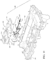
- an exemplary embodiment of another oil separator 220 is generally shown, wherein the same reference numerals as used above, offset by a factor of 200, are used to identify like features.
- the exemplary embodiment of the oil separator 220 is described in operable connection with an internal combustion engine of a vehicle, and is shown in a non-limiting embodiment as be disposed in a cam cover assembly 200 however, it should be appreciated that the oil separator 220 could also be incorporated within other vehicle engine components, such as a crank case, as discussed above, or within other systems, e.g., a refrigeration system.
- FIGS. 11-12 , and 14-17 an exemplary embodiment of another oil separator 220 is generally shown, wherein the same reference numerals as used above, offset by a factor of 200, are used to identify like features.
- the exemplary embodiment of the oil separator 220 is described in operable connection with an internal combustion engine of a vehicle, and is shown in a non-limiting embodiment as be disposed in a cam cover assembly 200 however, it should be appreciated that
- the oil separator 220 is disposed between an oil separator cover, also referred to as housing 222 that has a base 224, a top 226 and sidewalls 228.
- the sidewalls 228 define an inlet 236, that extends into a chamber for receiving oil-laden gases, and an oil outlet 244, that allows oil to flow freely therethrough under the force of gravity from the chamber back to an oil sump of the internal combustion engine, whereas the remaining gases are free to be expelled through a cam cover 202 of the assembly 220, such as via a standard gas recirculation valve (not shown, but known in the art).
- At least one or a plurality of baffles 240 can be disposed in the chamber bounded by the housing 222 and cam cover 202, such as adjacent the inlet 236.
- the baffles 240 can extend between the base 224 and the top 226, such as from the base 224, sidewalls 228 and/or top 226, to define a labyrinth passage for guiding the oil-laden gases after the oil-laden gases have entered the chamber through the inlet 236.
- the baffles 240 can be configured as discussed above for the baffles 40, and thus, no further discussion is believed necessary.
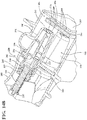
- the oil separator 220 includes a housing 258 having a plurality of generally tapered tube-shaped receptacles, also referred to as frames 246, that extend in laterally spaced, parallel relationship with one another.
- Each of the frames 246 are configured for receipt of a spiral member, also referred to as auger 266, therein.
- auger 266, a spiral member
- two frames 246 are shown; however, it should be appreciated that more could be included.
- Each of the frames 246 presents an outer surface 248 and an inner surface 250.
- each of the frames 246 bounds a channel, also referred to as cavity 252, shown as being frustroconical in shape, that extends between an inlet, also referred to as first opening 254, and an outlet, also referred to as second opening 256.
- the inner surface 250 is shown in a non-limiting embodiment as having a groove or channel 203 extending from the inlet 254 toward the outlet 256, wherein the channel 203 receives a mating protrusion 267 extending radially outwardly from the respective auger 266 to essentially close off the channel 203 adjacent the inlet 254 against a backflow of oil, wherein the channel 203 functions to drain coalesced oil toward and through the outlet 256, as discussed further below.
- the inner surface 250 is further shown as having one of a protrusion or recess, shown in a non-limiting embodiment as having a recess in the form of an annular groove 205 extending therein adjacent the inlet 254.
- the annular grooves 205 facilitate fixation of the augers 266 in the respective cavities 252 of the frames 246.
- the housing 258 is preferably formed as a monolithic piece of material, such as in a molding operation, by way of example and without limitation, and thus, the plurality of frames 246 are formed as a monolithic piece of material with the housing 258.
- the housing 258 and the frames 246 could be otherwise fixed to one another as separate pieces of material.
- the housing 258 is configured to be fixed between the cam cover 202 and the oil separator cover 222, and in one non-limiting embodiment, the housing 258 is configured to be fixed to the oil separator cover 222, such as in a gluing or welding operation, by way of example and without limitation, whereupon the integral subassembly of the oil separator cover 222 and the oil separator 220 can then be assembled to the cam cover 202.
- the housing 258 can be provided having a generally U-shaped channel 204 sized for close or snug receipt of a flange 206 of the oil separator cover 222 therein.
- a rib 208 of material shown as being a rib of oil separator cover material within the channel 204 can be provided, wherein the rib 208 of material can be subsequently melted in a welding operation to permanently fix the oil separator cover 222 to the housing 258.
- the channel 204 and rib 208 could be reversed to be on opposite parts, or that they could configured differently than shown.
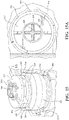
- the augers 266 each have a helical flight 270 extending about a longitudinal central axis 207 between a proximal end, also referred to as an inlet end 209, and a distal end, also referred to as an outlet end 211. Each of the augers 266 is disposed in a separate one of the cavities 252 to form helical flow paths about the associated central longitudinal axis 207. As shown in a non-limiting embodiment of FIG. 11A , the augers 266 can each be formed having the same configuration as one another, including the flights 270 having the same helical pitch and otherwise, or, as shown in another non-limiting embodiment of FIG.
- At least some of the augers 266, 266' can be formed having a different configuration from one another, wherein the flights 270, 270' of the respective augers 266, 266' can have a different helical pitch from one another, with other differences also being possible, with at least some shown and discussed hereafter.
- the augers 266, as shown in FIG. 11A include one auger 266 having its inlet end 209 left uncovered and open, thereby being freely and continuously exposed and open to flow of oil-laden gas therethrough during all vehicle operating conditions, and one auger 266 having an end wall or cover, also referred to as end cap 212 thereon. Accordingly, if oil-laden gas is present and flowing toward the inlet ends 209, the oil-laden gas is unobstructed and free to flow into the cavity 252 and around the uncovered auger 266.
- the auger 266 having the end cap 212 is predisposed to preventing the flow of the oil-laden gas into the cavity 252 and around the auger 266 under relatively low flow rate, low pressure conditions, such as when the vehicle is idling or otherwise operating in a low demand condition. Then, upon the flow rate and pressure increasing relative to the low flow rate, low pressure conditions, such as during vehicle acceleration, for example, as will be understood by one skilled in the art, an inlet 213 in the end cap 212 is automatically opened to the flow of oil-laden gas therethrough, such that the oil-laden gas can flow through the inlet 213 and about the additional auger 266 to further facilitate the efficient separation of oil mist from the gases.
- the end cap 212 is shown as being fixed to the inlet end 209 of the auger 266, wherein the inlet end 209 is presented at a free end of an annular wall 214 which extends from the inlet end 209 about the longitudinal central axis 207 toward the helical flight 270 to bound an inlet chamber 215 of the auger 266.
- the end cap 212 has an annular outer periphery 216 extending between an upper wall 217 and a lower wall 218, with a plurality of webs 219 extending between the upper and lower walls 217, 218.
- a through opening 221 extends along the longitudinal central axis 207 through the upper and lower walls 217, 219 and the inlet 213 extends into the outer periphery 216 between the webs 219 and through the lower wall 218. As such, the through opening 221 and the inlet 213 merge with one another through the lower wall 218.
- the augers 266, 266' have one of a protrusion or a recess, shown in a non-limiting embodiment as a protrusion 223 configured for snapping receipt in the corresponding recess 205 in the inner surface 250 of the frames 246.
- the protrusion 223 is shown as an annular rib 223 configured for snapping receipt in the annular groove 205.
- the augers 266, 266' are interchangeable with one another during assembly, and thus, the oil separator 220 can be configured as desired, having augers 266 with helical flights 270 having the same pitch, or having augers 266, 266' with different helical pitches.
- the augers 266 having a larger helical pitch reduce the pressure drop between the inlet end 209 and outlet end 211 and provide an increased velocity of the gases through the cavity 252, while the augers 266' having a smaller helical pitch increase the centripetal force of the oil-laden gases, thereby facilitating separation of the oil droplets for the oil-laden gases at reduced flow rate operating conditions. Accordingly, a predetermined matching of the augers 266, 266' results in an optimal, efficient operation of the oil separator 220.
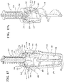
- the oil separator 220 includes a plunger valve 227 having a valve head 229 disposed in the inlet chamber 215.
- the valve head 229 is configured to move automatically into and out of sealed relation with a valve seat 213' at the inlet 213 in response to varying operating conditions.
- valve head 229 Under relatively low flow rate, low pressure conditions, the valve head 229 remains in a sealed relation with the valve seat 213' at the inlet 213, and then, upon the flow rate and pressure increasing relative to the low flow rate, low pressure conditions, such as during vehicle acceleration, the valve head 229 moves out from sealed engagement with the valve seat 213' at the inlet 213, and if the flow rate of the oil-laden gas is sufficient to fully open the plunger valve 227, the valve head 229 moves into engagement with a valve head stop surface 232, shown as a protrusion or rib projecting radially inwardly from the annular wall 214 of the auger 266 such that the stop surface 232 confronts the valve head 229 to limit the movement of the valve head 229 within the inlet chamber 215 away from the end cap 212 to provide a maximum flow through configuration.
- a valve head stop surface 232 shown as a protrusion or rib projecting radially inwardly from the annular wall 214 of the auger 266 such that the stop surface
- the plunger valve 227 has a valve stem 231 extending from the valve head 229 along the longitudinal central axis 207 through the through opening 221 in the upper wall 217.
- the valve stem 231 includes at least a portion, and is shown in its entirety as having a non-circular outer peripheral surface 233, as viewed in cross-section taken transversely to the longitudinal central axis 207. With the through opening 221 in the upper wall 217 having a peripheral surface conforming at least in part, and shown in its entirety, with the non-circular outer peripheral surface 233 of the valve stem 231, lateral play of the valve stem 231 within the through opening 221 in the upper wall 217 is inhibited.
- the lateral cross-sectional shape of the outer peripheral surface 233 is generally cross or X-shaped with a corresponding shape being provided by the periphery of the through opening 221.
- the periphery of the through opening 221 corresponding with the inlet 213 in the lower wall 218 is enlarged relative to the outer peripheral surface 233 of the valve stem 231 to allow the free flow of gases through the inlet 213 upon the valve head 229 being biased to the open position.
- the oil separator 220 includes a spring member 235 configured to bias the valve head 229 into the closed position in sealed abutment with the end cap 212 to perfect a seal over the inlet 213 to inhibit the flow of oil-laden gases therethrough.
- the valve head 229 is moveable within the chamber 215 against the bias of the spring member 235 to an open position spaced axially away from the lower wall 218 of the end cap 212 in response to pressure being applied against the valve head 229 sufficient to overcome the bias of the spring member 235.
- the spring member 235 can be provided as a coil spring disposed about the valve stem 231.
- the spring member 235 is captured between the upper wall 217 of the end cap 212 and a retaining feature, shown as a retaining member 237 that is fixed to the valve stem 231, such as via a heat-staked portion of the valve stem 231, by way of example and without limitation.
- the retaining member 237 can be provided as a washer or the like, disposed on an end of the valve stem 231, whereupon the end of the valve stem 231 can be heat-staked or other deformed to fix the retaining member 237 in the desired compressed position against a bias of the spring member 235.
- the compressive bias applied by the spring member 235 against the upper wall 217 and the retaining member 237 forces the valve head 229 into sealed relation about the inlet 213.
- the spring force of the spring member 235 can be selected as desired to allow the force required to move the valve head 229 out of sealed engagement about the inlet 213 to be precisely regulated.
- a fine mist separator assembly 284 is disposed downstream of the outlet second openings 256 for further separating oil from the oil-laden gases after the oil-laden gases have passed through the frames 246, as discussed above.
- the fine mist separator assembly 284 includes a generally rectangular-shaped fibrous pad 286 that is porous and disposed adjacent to and in alignment with the second openings 256 of the frames 246 for further absorbing oil in the oil-laden gases to further separate oil from the oil-laden gases.
- the fibrous pad 286 can be made of a nonwoven nylon felt material, however, it should be appreciated that other materials could be utilized without departing from the scope of the subject disclosure, wherein the pad can be adhered, welded or otherwise fixed to the cover 202, by way of example and without limitation.
- the fine mist separator assembly 84 also includes a generally rectangular-shaped impactor wall 287 that is disposed adjacent to the fibrous pad 286.
- the impactor wall 287 is shown as being formed as an integral, monolithic piece with the cover 202, though it could be formed separately and attached thereto, if desired.
- the impactor wall 287 has a plurality of indentations 289 that further separate the oil from the oil-laden gases during contact of the oil-laden gases with the impactor wall 287, and channel the separated oil toward the oil outlet 244. Meanwhile, "clean,” substantially oil-free gases pass over the impactor wall 287 toward a gas outlet. It should be appreciated that the fine mist separator assembly 284 could be configured otherwise, such as without the fibrous pad 286, as discussed above.
- valve head 229 In use, depending on the operating conditions of the vehicle, the valve head 229 will either remain in closed and sealed relation against the valve seat 213' (i.e., under low flow conditions, such as at idle), thereby directing the entirety of the flow of oil-laden gasses through the uncovered auger(s) 266, as discussed above, or the valve head 229 will move out of sealed relation from the valve seat 213' to an open position (i.e., under relatively increased flow conditions, such as during acceleration or other high demand use conditions), thereby distributing the of the flow of oil-laden gasses through both the uncovered auger(s) 266 and the augers 266 including the plunger valve 227.
- the opening and closing of the plunger valve 227 can be controlled by selecting a spring member 235 having the desired spring constant(s). Accordingly, if a plurality of the plunger valves 227 is provided in the assembly 200, different ones of the plunger valves 227 can be provided having spring members 235 with different spring constants from one another, thereby causing the respective plunger valves 227 to open under different flow rates/pressures from one another, thus, providing optimal flow of the oil-laden gases through the oil separator 220 and maximizing the efficiency in which the oil is separated from the oil-laden gases. Further, as discussed above, the helical pitches of the different augers 266, 266' can be varied from one another as desired for the intended vehicle platform. Of course, as discussed above, at least one of the plurality of augers 266, 266' can be provided not having a valve head 229 disposed therein, thereby being continuously open to the flow of oil-laden gases therethrough.
Applications Claiming Priority (1)
| Application Number | Priority Date | Filing Date | Title |
|---|---|---|---|
| US15/848,102 US10286347B2 (en) | 2015-09-15 | 2017-12-20 | Oil separator including spiral members defining helical flow paths |
Publications (2)
| Publication Number | Publication Date |
|---|---|
| EP3502427A1 true EP3502427A1 (fr) | 2019-06-26 |
| EP3502427B1 EP3502427B1 (fr) | 2021-09-01 |
Family
ID=64746215
Family Applications (1)
| Application Number | Title | Priority Date | Filing Date |
|---|---|---|---|
| EP18214132.5A Active EP3502427B1 (fr) | 2017-12-20 | 2018-12-19 | Séparateur d'huile comprenant des éléments en spirale délimitant des trajets d'écoulement hélicoïdaux |
Country Status (6)
| Country | Link |
|---|---|
| EP (1) | EP3502427B1 (fr) |
| KR (1) | KR20190074992A (fr) |
| CN (1) | CN109944660B (fr) |
| CA (1) | CA3027567C (fr) |
| ES (1) | ES2901633T3 (fr) |
| MX (1) | MX2018015786A (fr) |
Citations (6)
| Publication number | Priority date | Publication date | Assignee | Title |
|---|---|---|---|---|
| US6860915B2 (en) | 2001-06-07 | 2005-03-01 | Robert Bosch Gmbh | Oil separating device for crankcase gases of an internal combustion engine |
| WO2005049176A1 (fr) * | 2003-11-12 | 2005-06-02 | Mecaplast S.A.M. | Dispositif separateur d’huile |
| US20130118357A1 (en) * | 2010-06-02 | 2013-05-16 | Juergen Meusel | Tubular camshaft with integrated oil separator |
| JP2014125929A (ja) * | 2012-12-26 | 2014-07-07 | Sanoh Industrial Co Ltd | オイルセパレータ |
| JP2017025823A (ja) * | 2015-07-23 | 2017-02-02 | トヨタ紡織株式会社 | Pcvバルブ |
| US20170072352A1 (en) * | 2015-09-15 | 2017-03-16 | Miniature Precision Components, Inc. | Oil separator including spiral members defining helical flow paths |
Family Cites Families (4)
| Publication number | Priority date | Publication date | Assignee | Title |
|---|---|---|---|---|
| EP0341282B1 (fr) * | 1987-11-24 | 1994-05-11 | Conoco Specialty Products Inc. | Separateur a cyclone |
| BRPI0508511B1 (pt) * | 2004-03-08 | 2018-07-17 | Reinz-Dichtungs-Gmbh. | tampa de cabeçote do bloco dos cilindros para cobrir um cabeçote de um motor de combustão interna |
| DE102005042286A1 (de) * | 2005-09-06 | 2007-04-12 | Mahle International Gmbh | Einrichtung zur Trennung eines Gas-Flüssigkeitsgemisches |
| DE102008017919A1 (de) * | 2008-04-08 | 2009-10-15 | Mann + Hummel Gmbh | Abscheider für eine Kurbelgehäuseentlüftung einer Brennkraftmaschine |
-
2018
- 2018-12-14 CA CA3027567A patent/CA3027567C/fr active Active
- 2018-12-14 MX MX2018015786A patent/MX2018015786A/es unknown
- 2018-12-19 ES ES18214132T patent/ES2901633T3/es active Active
- 2018-12-19 CN CN201811554736.8A patent/CN109944660B/zh active Active
- 2018-12-19 EP EP18214132.5A patent/EP3502427B1/fr active Active
- 2018-12-19 KR KR1020180164961A patent/KR20190074992A/ko not_active Application Discontinuation
Patent Citations (6)
| Publication number | Priority date | Publication date | Assignee | Title |
|---|---|---|---|---|
| US6860915B2 (en) | 2001-06-07 | 2005-03-01 | Robert Bosch Gmbh | Oil separating device for crankcase gases of an internal combustion engine |
| WO2005049176A1 (fr) * | 2003-11-12 | 2005-06-02 | Mecaplast S.A.M. | Dispositif separateur d’huile |
| US20130118357A1 (en) * | 2010-06-02 | 2013-05-16 | Juergen Meusel | Tubular camshaft with integrated oil separator |
| JP2014125929A (ja) * | 2012-12-26 | 2014-07-07 | Sanoh Industrial Co Ltd | オイルセパレータ |
| JP2017025823A (ja) * | 2015-07-23 | 2017-02-02 | トヨタ紡織株式会社 | Pcvバルブ |
| US20170072352A1 (en) * | 2015-09-15 | 2017-03-16 | Miniature Precision Components, Inc. | Oil separator including spiral members defining helical flow paths |
Also Published As
| Publication number | Publication date |
|---|---|
| CA3027567A1 (fr) | 2019-06-20 |
| KR20190074992A (ko) | 2019-06-28 |
| EP3502427B1 (fr) | 2021-09-01 |
| ES2901633T3 (es) | 2022-03-23 |
| MX2018015786A (es) | 2019-08-29 |
| CA3027567C (fr) | 2023-02-21 |
| CN109944660A (zh) | 2019-06-28 |
| CN109944660B (zh) | 2022-04-01 |
Similar Documents
| Publication | Publication Date | Title |
|---|---|---|
| US10661210B2 (en) | Oil separator including spiral members defining helical flow paths | |
| US10286347B2 (en) | Oil separator including spiral members defining helical flow paths | |
| US4723529A (en) | Oil separator for a blowby gas ventilation system of an internal combustion engine | |
| US7380545B2 (en) | Oil drain device for an engine oil separator | |
| US9885266B2 (en) | Oil mist separator | |
| US7140358B1 (en) | Oil separator | |
| US5129371A (en) | Cam cover oil separator for crankcase ventilation | |
| US9598992B2 (en) | Separation device for an aerosol stream | |
| ITMI970929U1 (it) | Sfiato del basamento con integrate funzioni aggiuntive | |
| WO2006020672A1 (fr) | Dispositif de separation air/huile | |
| EP3597877B1 (fr) | Dispositif de séparation d'huile et de gaz d'un moteur à combustion interne | |
| JP2004521236A (ja) | 内燃機関のクランクケーシングガスのためのオイル分離装置 | |
| US7246612B2 (en) | Oil separator | |
| US7219629B2 (en) | Breathing system in combustion engine | |
| US8156926B2 (en) | Systems and methods for filtering crankcase fumes | |
| US20060102159A1 (en) | Protruding oil separation baffle holes | |
| CA3027567C (fr) | Separateur d'huile comportant des elements en spirale definissant des parcours d'ecoulement helicoidaux | |
| CN104033209B (zh) | 从发动机窜气分离机油的发动机组件及其方法 | |
| CN111315466B (zh) | 曲轴箱通风中的油管理结构 | |
| CN111197512B (zh) | 油雾分离器 | |
| CN113272531B (zh) | 内燃机 | |
| CN103184912B (zh) | 发动机曲轴箱油气分离系统 | |
| JPH0622108Y2 (ja) | エンジンのブローバイガス取出構造 | |
| EP1199448A1 (fr) | Moteur à combustion avec un dispositif pour séparer les particules d'huile de lubrification des gas de carter | |
| JP2021173217A (ja) | 調圧装置 |
Legal Events
| Date | Code | Title | Description |
|---|---|---|---|
| PUAI | Public reference made under article 153(3) epc to a published international application that has entered the european phase |
Free format text: ORIGINAL CODE: 0009012 |
|
| STAA | Information on the status of an ep patent application or granted ep patent |
Free format text: STATUS: THE APPLICATION HAS BEEN PUBLISHED |
|
| AK | Designated contracting states |
Kind code of ref document: A1 Designated state(s): AL AT BE BG CH CY CZ DE DK EE ES FI FR GB GR HR HU IE IS IT LI LT LU LV MC MK MT NL NO PL PT RO RS SE SI SK SM TR |
|
| AX | Request for extension of the european patent |
Extension state: BA ME |
|
| STAA | Information on the status of an ep patent application or granted ep patent |
Free format text: STATUS: REQUEST FOR EXAMINATION WAS MADE |
|
| 17P | Request for examination filed |
Effective date: 20190812 |
|
| RBV | Designated contracting states (corrected) |
Designated state(s): AL AT BE BG CH CY CZ DE DK EE ES FI FR GB GR HR HU IE IS IT LI LT LU LV MC MK MT NL NO PL PT RO RS SE SI SK SM TR |
|
| RAP1 | Party data changed (applicant data changed or rights of an application transferred) |
Owner name: NOVARES US ENGINE COMPONENTS, INC. |
|
| GRAP | Despatch of communication of intention to grant a patent |
Free format text: ORIGINAL CODE: EPIDOSNIGR1 |
|
| STAA | Information on the status of an ep patent application or granted ep patent |
Free format text: STATUS: GRANT OF PATENT IS INTENDED |
|
| INTG | Intention to grant announced |
Effective date: 20210330 |
|
| GRAS | Grant fee paid |
Free format text: ORIGINAL CODE: EPIDOSNIGR3 |
|
| GRAA | (expected) grant |
Free format text: ORIGINAL CODE: 0009210 |
|
| STAA | Information on the status of an ep patent application or granted ep patent |
Free format text: STATUS: THE PATENT HAS BEEN GRANTED |
|
| AK | Designated contracting states |
Kind code of ref document: B1 Designated state(s): AL AT BE BG CH CY CZ DE DK EE ES FI FR GB GR HR HU IE IS IT LI LT LU LV MC MK MT NL NO PL PT RO RS SE SI SK SM TR |
|
| REG | Reference to a national code |
Ref country code: GB Ref legal event code: FG4D |
|
| REG | Reference to a national code |
Ref country code: CH Ref legal event code: EP Ref country code: AT Ref legal event code: REF Ref document number: 1426464 Country of ref document: AT Kind code of ref document: T Effective date: 20210915 |
|
| REG | Reference to a national code |
Ref country code: DE Ref legal event code: R096 Ref document number: 602018022755 Country of ref document: DE |
|
| REG | Reference to a national code |
Ref country code: IE Ref legal event code: FG4D |
|
| REG | Reference to a national code |
Ref country code: LT Ref legal event code: MG9D |
|
| REG | Reference to a national code |
Ref country code: NL Ref legal event code: MP Effective date: 20210901 |
|
| PG25 | Lapsed in a contracting state [announced via postgrant information from national office to epo] |
Ref country code: HR Free format text: LAPSE BECAUSE OF FAILURE TO SUBMIT A TRANSLATION OF THE DESCRIPTION OR TO PAY THE FEE WITHIN THE PRESCRIBED TIME-LIMIT Effective date: 20210901 Ref country code: FI Free format text: LAPSE BECAUSE OF FAILURE TO SUBMIT A TRANSLATION OF THE DESCRIPTION OR TO PAY THE FEE WITHIN THE PRESCRIBED TIME-LIMIT Effective date: 20210901 Ref country code: RS Free format text: LAPSE BECAUSE OF FAILURE TO SUBMIT A TRANSLATION OF THE DESCRIPTION OR TO PAY THE FEE WITHIN THE PRESCRIBED TIME-LIMIT Effective date: 20210901 Ref country code: SE Free format text: LAPSE BECAUSE OF FAILURE TO SUBMIT A TRANSLATION OF THE DESCRIPTION OR TO PAY THE FEE WITHIN THE PRESCRIBED TIME-LIMIT Effective date: 20210901 Ref country code: NO Free format text: LAPSE BECAUSE OF FAILURE TO SUBMIT A TRANSLATION OF THE DESCRIPTION OR TO PAY THE FEE WITHIN THE PRESCRIBED TIME-LIMIT Effective date: 20211201 Ref country code: BG Free format text: LAPSE BECAUSE OF FAILURE TO SUBMIT A TRANSLATION OF THE DESCRIPTION OR TO PAY THE FEE WITHIN THE PRESCRIBED TIME-LIMIT Effective date: 20211201 Ref country code: LT Free format text: LAPSE BECAUSE OF FAILURE TO SUBMIT A TRANSLATION OF THE DESCRIPTION OR TO PAY THE FEE WITHIN THE PRESCRIBED TIME-LIMIT Effective date: 20210901 |
|
| REG | Reference to a national code |
Ref country code: AT Ref legal event code: MK05 Ref document number: 1426464 Country of ref document: AT Kind code of ref document: T Effective date: 20210901 |
|
| PG25 | Lapsed in a contracting state [announced via postgrant information from national office to epo] |
Ref country code: PL Free format text: LAPSE BECAUSE OF FAILURE TO SUBMIT A TRANSLATION OF THE DESCRIPTION OR TO PAY THE FEE WITHIN THE PRESCRIBED TIME-LIMIT Effective date: 20210901 Ref country code: LV Free format text: LAPSE BECAUSE OF FAILURE TO SUBMIT A TRANSLATION OF THE DESCRIPTION OR TO PAY THE FEE WITHIN THE PRESCRIBED TIME-LIMIT Effective date: 20210901 Ref country code: GR Free format text: LAPSE BECAUSE OF FAILURE TO SUBMIT A TRANSLATION OF THE DESCRIPTION OR TO PAY THE FEE WITHIN THE PRESCRIBED TIME-LIMIT Effective date: 20211202 |
|
| REG | Reference to a national code |
Ref country code: ES Ref legal event code: FG2A Ref document number: 2901633 Country of ref document: ES Kind code of ref document: T3 Effective date: 20220323 |
|
| PG25 | Lapsed in a contracting state [announced via postgrant information from national office to epo] |
Ref country code: AT Free format text: LAPSE BECAUSE OF FAILURE TO SUBMIT A TRANSLATION OF THE DESCRIPTION OR TO PAY THE FEE WITHIN THE PRESCRIBED TIME-LIMIT Effective date: 20210901 |
|
| PG25 | Lapsed in a contracting state [announced via postgrant information from national office to epo] |
Ref country code: IS Free format text: LAPSE BECAUSE OF FAILURE TO SUBMIT A TRANSLATION OF THE DESCRIPTION OR TO PAY THE FEE WITHIN THE PRESCRIBED TIME-LIMIT Effective date: 20220101 Ref country code: SM Free format text: LAPSE BECAUSE OF FAILURE TO SUBMIT A TRANSLATION OF THE DESCRIPTION OR TO PAY THE FEE WITHIN THE PRESCRIBED TIME-LIMIT Effective date: 20210901 Ref country code: SK Free format text: LAPSE BECAUSE OF FAILURE TO SUBMIT A TRANSLATION OF THE DESCRIPTION OR TO PAY THE FEE WITHIN THE PRESCRIBED TIME-LIMIT Effective date: 20210901 Ref country code: RO Free format text: LAPSE BECAUSE OF FAILURE TO SUBMIT A TRANSLATION OF THE DESCRIPTION OR TO PAY THE FEE WITHIN THE PRESCRIBED TIME-LIMIT Effective date: 20210901 Ref country code: PT Free format text: LAPSE BECAUSE OF FAILURE TO SUBMIT A TRANSLATION OF THE DESCRIPTION OR TO PAY THE FEE WITHIN THE PRESCRIBED TIME-LIMIT Effective date: 20220103 Ref country code: NL Free format text: LAPSE BECAUSE OF FAILURE TO SUBMIT A TRANSLATION OF THE DESCRIPTION OR TO PAY THE FEE WITHIN THE PRESCRIBED TIME-LIMIT Effective date: 20210901 Ref country code: EE Free format text: LAPSE BECAUSE OF FAILURE TO SUBMIT A TRANSLATION OF THE DESCRIPTION OR TO PAY THE FEE WITHIN THE PRESCRIBED TIME-LIMIT Effective date: 20210901 Ref country code: CZ Free format text: LAPSE BECAUSE OF FAILURE TO SUBMIT A TRANSLATION OF THE DESCRIPTION OR TO PAY THE FEE WITHIN THE PRESCRIBED TIME-LIMIT Effective date: 20210901 Ref country code: AL Free format text: LAPSE BECAUSE OF FAILURE TO SUBMIT A TRANSLATION OF THE DESCRIPTION OR TO PAY THE FEE WITHIN THE PRESCRIBED TIME-LIMIT Effective date: 20210901 |
|
| REG | Reference to a national code |
Ref country code: DE Ref legal event code: R097 Ref document number: 602018022755 Country of ref document: DE |
|
| PLBE | No opposition filed within time limit |
Free format text: ORIGINAL CODE: 0009261 |
|
| STAA | Information on the status of an ep patent application or granted ep patent |
Free format text: STATUS: NO OPPOSITION FILED WITHIN TIME LIMIT |
|
| PG25 | Lapsed in a contracting state [announced via postgrant information from national office to epo] |
Ref country code: MC Free format text: LAPSE BECAUSE OF FAILURE TO SUBMIT A TRANSLATION OF THE DESCRIPTION OR TO PAY THE FEE WITHIN THE PRESCRIBED TIME-LIMIT Effective date: 20210901 Ref country code: IT Free format text: LAPSE BECAUSE OF FAILURE TO SUBMIT A TRANSLATION OF THE DESCRIPTION OR TO PAY THE FEE WITHIN THE PRESCRIBED TIME-LIMIT Effective date: 20210901 Ref country code: DK Free format text: LAPSE BECAUSE OF FAILURE TO SUBMIT A TRANSLATION OF THE DESCRIPTION OR TO PAY THE FEE WITHIN THE PRESCRIBED TIME-LIMIT Effective date: 20210901 |
|
| REG | Reference to a national code |
Ref country code: CH Ref legal event code: PL |
|
| 26N | No opposition filed |
Effective date: 20220602 |
|
| PG25 | Lapsed in a contracting state [announced via postgrant information from national office to epo] |
Ref country code: SI Free format text: LAPSE BECAUSE OF FAILURE TO SUBMIT A TRANSLATION OF THE DESCRIPTION OR TO PAY THE FEE WITHIN THE PRESCRIBED TIME-LIMIT Effective date: 20210901 |
|
| REG | Reference to a national code |
Ref country code: BE Ref legal event code: MM Effective date: 20211231 |
|
| PG25 | Lapsed in a contracting state [announced via postgrant information from national office to epo] |
Ref country code: LU Free format text: LAPSE BECAUSE OF NON-PAYMENT OF DUE FEES Effective date: 20211219 Ref country code: IE Free format text: LAPSE BECAUSE OF NON-PAYMENT OF DUE FEES Effective date: 20211219 |
|
| PG25 | Lapsed in a contracting state [announced via postgrant information from national office to epo] |
Ref country code: BE Free format text: LAPSE BECAUSE OF NON-PAYMENT OF DUE FEES Effective date: 20211231 |
|
| PG25 | Lapsed in a contracting state [announced via postgrant information from national office to epo] |
Ref country code: LI Free format text: LAPSE BECAUSE OF NON-PAYMENT OF DUE FEES Effective date: 20211231 Ref country code: CH Free format text: LAPSE BECAUSE OF NON-PAYMENT OF DUE FEES Effective date: 20211231 |
|
| PGFP | Annual fee paid to national office [announced via postgrant information from national office to epo] |
Ref country code: ES Payment date: 20230102 Year of fee payment: 5 |
|
| PGFP | Annual fee paid to national office [announced via postgrant information from national office to epo] |
Ref country code: DE Payment date: 20221228 Year of fee payment: 5 |
|
| PG25 | Lapsed in a contracting state [announced via postgrant information from national office to epo] |
Ref country code: CY Free format text: LAPSE BECAUSE OF FAILURE TO SUBMIT A TRANSLATION OF THE DESCRIPTION OR TO PAY THE FEE WITHIN THE PRESCRIBED TIME-LIMIT Effective date: 20210901 |
|
| PG25 | Lapsed in a contracting state [announced via postgrant information from national office to epo] |
Ref country code: HU Free format text: LAPSE BECAUSE OF FAILURE TO SUBMIT A TRANSLATION OF THE DESCRIPTION OR TO PAY THE FEE WITHIN THE PRESCRIBED TIME-LIMIT; INVALID AB INITIO Effective date: 20181219 |
|
| GBPC | Gb: european patent ceased through non-payment of renewal fee |
Effective date: 20221219 |
|
| PG25 | Lapsed in a contracting state [announced via postgrant information from national office to epo] |
Ref country code: GB Free format text: LAPSE BECAUSE OF NON-PAYMENT OF DUE FEES Effective date: 20221219 |
|
| PGFP | Annual fee paid to national office [announced via postgrant information from national office to epo] |
Ref country code: FR Payment date: 20231222 Year of fee payment: 6 |
|
| PGFP | Annual fee paid to national office [announced via postgrant information from national office to epo] |
Ref country code: ES Payment date: 20240129 Year of fee payment: 6 |
|
| PG25 | Lapsed in a contracting state [announced via postgrant information from national office to epo] |
Ref country code: MK Free format text: LAPSE BECAUSE OF FAILURE TO SUBMIT A TRANSLATION OF THE DESCRIPTION OR TO PAY THE FEE WITHIN THE PRESCRIBED TIME-LIMIT Effective date: 20210901 |
|
| PGFP | Annual fee paid to national office [announced via postgrant information from national office to epo] |
Ref country code: DE Payment date: 20240227 Year of fee payment: 6 |