EP3501810A1 - Pultruded fibrous composite strips having corrugated profiles for wind turbine blade spar caps - Google Patents
Pultruded fibrous composite strips having corrugated profiles for wind turbine blade spar caps Download PDFInfo
- Publication number
- EP3501810A1 EP3501810A1 EP17210037.2A EP17210037A EP3501810A1 EP 3501810 A1 EP3501810 A1 EP 3501810A1 EP 17210037 A EP17210037 A EP 17210037A EP 3501810 A1 EP3501810 A1 EP 3501810A1
- Authority
- EP
- European Patent Office
- Prior art keywords
- strip
- strips
- abutment surface
- wind turbine
- stack
- Prior art date
- Legal status (The legal status is an assumption and is not a legal conclusion. Google has not performed a legal analysis and makes no representation as to the accuracy of the status listed.)
- Granted
Links
- 239000002131 composite material Substances 0.000 title claims abstract description 36
- 238000000034 method Methods 0.000 claims abstract description 100
- 229920005989 resin Polymers 0.000 claims abstract description 60
- 239000011347 resin Substances 0.000 claims abstract description 60
- 230000002093 peripheral effect Effects 0.000 description 21
- 238000004519 manufacturing process Methods 0.000 description 14
- 239000000835 fiber Substances 0.000 description 11
- 238000001802 infusion Methods 0.000 description 11
- 238000010276 construction Methods 0.000 description 7
- 230000008569 process Effects 0.000 description 7
- 230000007246 mechanism Effects 0.000 description 6
- 239000011159 matrix material Substances 0.000 description 4
- 229920002430 Fibre-reinforced plastic Polymers 0.000 description 3
- 230000008901 benefit Effects 0.000 description 3
- 230000002787 reinforcement Effects 0.000 description 3
- OKTJSMMVPCPJKN-UHFFFAOYSA-N Carbon Chemical compound [C] OKTJSMMVPCPJKN-UHFFFAOYSA-N 0.000 description 2
- 239000004593 Epoxy Substances 0.000 description 2
- 239000004760 aramid Substances 0.000 description 2
- 229920003235 aromatic polyamide Polymers 0.000 description 2
- 229910052799 carbon Inorganic materials 0.000 description 2
- 239000003795 chemical substances by application Substances 0.000 description 2
- 238000013461 design Methods 0.000 description 2
- 239000011151 fibre-reinforced plastic Substances 0.000 description 2
- 239000012530 fluid Substances 0.000 description 2
- 239000011521 glass Substances 0.000 description 2
- 239000003365 glass fiber Substances 0.000 description 2
- 238000009787 hand lay-up Methods 0.000 description 2
- 238000010348 incorporation Methods 0.000 description 2
- 239000000463 material Substances 0.000 description 2
- 238000005259 measurement Methods 0.000 description 2
- 238000012986 modification Methods 0.000 description 2
- 230000004048 modification Effects 0.000 description 2
- 230000000737 periodic effect Effects 0.000 description 2
- 229920000728 polyester Polymers 0.000 description 2
- 229920002635 polyurethane Polymers 0.000 description 2
- 239000004814 polyurethane Substances 0.000 description 2
- 238000002360 preparation method Methods 0.000 description 2
- 238000007788 roughening Methods 0.000 description 2
- 229920001567 vinyl ester resin Polymers 0.000 description 2
- 229920000049 Carbon (fiber) Polymers 0.000 description 1
- 240000007182 Ochroma pyramidale Species 0.000 description 1
- 229920005830 Polyurethane Foam Polymers 0.000 description 1
- 239000004917 carbon fiber Substances 0.000 description 1
- 238000004891 communication Methods 0.000 description 1
- 239000000470 constituent Substances 0.000 description 1
- 238000010924 continuous production Methods 0.000 description 1
- 238000003851 corona treatment Methods 0.000 description 1
- 230000032798 delamination Effects 0.000 description 1
- 230000001419 dependent effect Effects 0.000 description 1
- 238000011161 development Methods 0.000 description 1
- 230000018109 developmental process Effects 0.000 description 1
- 238000001125 extrusion Methods 0.000 description 1
- 239000012467 final product Substances 0.000 description 1
- 239000006260 foam Substances 0.000 description 1
- 238000000227 grinding Methods 0.000 description 1
- 238000010438 heat treatment Methods 0.000 description 1
- 238000005470 impregnation Methods 0.000 description 1
- 238000001746 injection moulding Methods 0.000 description 1
- 239000003562 lightweight material Substances 0.000 description 1
- 239000007788 liquid Substances 0.000 description 1
- 238000009832 plasma treatment Methods 0.000 description 1
- 239000011496 polyurethane foam Substances 0.000 description 1
- 238000010248 power generation Methods 0.000 description 1
- 230000008439 repair process Effects 0.000 description 1
- 238000005488 sandblasting Methods 0.000 description 1
- 230000002123 temporal effect Effects 0.000 description 1
- 238000001721 transfer moulding Methods 0.000 description 1
- 230000007704 transition Effects 0.000 description 1
- 230000037303 wrinkles Effects 0.000 description 1
Images


Classifications
-
- B—PERFORMING OPERATIONS; TRANSPORTING
- B29—WORKING OF PLASTICS; WORKING OF SUBSTANCES IN A PLASTIC STATE IN GENERAL
- B29C—SHAPING OR JOINING OF PLASTICS; SHAPING OF MATERIAL IN A PLASTIC STATE, NOT OTHERWISE PROVIDED FOR; AFTER-TREATMENT OF THE SHAPED PRODUCTS, e.g. REPAIRING
- B29C70/00—Shaping composites, i.e. plastics material comprising reinforcements, fillers or preformed parts, e.g. inserts
- B29C70/04—Shaping composites, i.e. plastics material comprising reinforcements, fillers or preformed parts, e.g. inserts comprising reinforcements only, e.g. self-reinforcing plastics
- B29C70/28—Shaping operations therefor
- B29C70/30—Shaping by lay-up, i.e. applying fibres, tape or broadsheet on a mould, former or core; Shaping by spray-up, i.e. spraying of fibres on a mould, former or core
- B29C70/34—Shaping by lay-up, i.e. applying fibres, tape or broadsheet on a mould, former or core; Shaping by spray-up, i.e. spraying of fibres on a mould, former or core and shaping or impregnating by compression, i.e. combined with compressing after the lay-up operation
- B29C70/345—Shaping by lay-up, i.e. applying fibres, tape or broadsheet on a mould, former or core; Shaping by spray-up, i.e. spraying of fibres on a mould, former or core and shaping or impregnating by compression, i.e. combined with compressing after the lay-up operation using matched moulds
-
- B—PERFORMING OPERATIONS; TRANSPORTING
- B29—WORKING OF PLASTICS; WORKING OF SUBSTANCES IN A PLASTIC STATE IN GENERAL
- B29C—SHAPING OR JOINING OF PLASTICS; SHAPING OF MATERIAL IN A PLASTIC STATE, NOT OTHERWISE PROVIDED FOR; AFTER-TREATMENT OF THE SHAPED PRODUCTS, e.g. REPAIRING
- B29C70/00—Shaping composites, i.e. plastics material comprising reinforcements, fillers or preformed parts, e.g. inserts
- B29C70/04—Shaping composites, i.e. plastics material comprising reinforcements, fillers or preformed parts, e.g. inserts comprising reinforcements only, e.g. self-reinforcing plastics
- B29C70/28—Shaping operations therefor
- B29C70/40—Shaping or impregnating by compression not applied
- B29C70/50—Shaping or impregnating by compression not applied for producing articles of indefinite length, e.g. prepregs, sheet moulding compounds [SMC] or cross moulding compounds [XMC]
- B29C70/52—Pultrusion, i.e. forming and compressing by continuously pulling through a die
-
- B—PERFORMING OPERATIONS; TRANSPORTING
- B29—WORKING OF PLASTICS; WORKING OF SUBSTANCES IN A PLASTIC STATE IN GENERAL
- B29D—PRODUCING PARTICULAR ARTICLES FROM PLASTICS OR FROM SUBSTANCES IN A PLASTIC STATE
- B29D99/00—Subject matter not provided for in other groups of this subclass
- B29D99/0025—Producing blades or the like, e.g. blades for turbines, propellers, or wings
- B29D99/0028—Producing blades or the like, e.g. blades for turbines, propellers, or wings hollow blades
-
- F—MECHANICAL ENGINEERING; LIGHTING; HEATING; WEAPONS; BLASTING
- F03—MACHINES OR ENGINES FOR LIQUIDS; WIND, SPRING, OR WEIGHT MOTORS; PRODUCING MECHANICAL POWER OR A REACTIVE PROPULSIVE THRUST, NOT OTHERWISE PROVIDED FOR
- F03D—WIND MOTORS
- F03D1/00—Wind motors with rotation axis substantially parallel to the air flow entering the rotor
- F03D1/06—Rotors
- F03D1/065—Rotors characterised by their construction elements
- F03D1/0675—Rotors characterised by their construction elements of the blades
-
- B—PERFORMING OPERATIONS; TRANSPORTING
- B29—WORKING OF PLASTICS; WORKING OF SUBSTANCES IN A PLASTIC STATE IN GENERAL
- B29L—INDEXING SCHEME ASSOCIATED WITH SUBCLASS B29C, RELATING TO PARTICULAR ARTICLES
- B29L2031/00—Other particular articles
- B29L2031/08—Blades for rotors, stators, fans, turbines or the like, e.g. screw propellers
- B29L2031/082—Blades, e.g. for helicopters
- B29L2031/085—Wind turbine blades
-
- F—MECHANICAL ENGINEERING; LIGHTING; HEATING; WEAPONS; BLASTING
- F05—INDEXING SCHEMES RELATING TO ENGINES OR PUMPS IN VARIOUS SUBCLASSES OF CLASSES F01-F04
- F05B—INDEXING SCHEME RELATING TO WIND, SPRING, WEIGHT, INERTIA OR LIKE MOTORS, TO MACHINES OR ENGINES FOR LIQUIDS COVERED BY SUBCLASSES F03B, F03D AND F03G
- F05B2230/00—Manufacture
- F05B2230/20—Manufacture essentially without removing material
-
- F—MECHANICAL ENGINEERING; LIGHTING; HEATING; WEAPONS; BLASTING
- F05—INDEXING SCHEMES RELATING TO ENGINES OR PUMPS IN VARIOUS SUBCLASSES OF CLASSES F01-F04
- F05B—INDEXING SCHEME RELATING TO WIND, SPRING, WEIGHT, INERTIA OR LIKE MOTORS, TO MACHINES OR ENGINES FOR LIQUIDS COVERED BY SUBCLASSES F03B, F03D AND F03G
- F05B2240/00—Components
- F05B2240/20—Rotors
- F05B2240/30—Characteristics of rotor blades, i.e. of any element transforming dynamic fluid energy to or from rotational energy and being attached to a rotor
- F05B2240/301—Cross-section characteristics
-
- F—MECHANICAL ENGINEERING; LIGHTING; HEATING; WEAPONS; BLASTING
- F05—INDEXING SCHEMES RELATING TO ENGINES OR PUMPS IN VARIOUS SUBCLASSES OF CLASSES F01-F04
- F05B—INDEXING SCHEME RELATING TO WIND, SPRING, WEIGHT, INERTIA OR LIKE MOTORS, TO MACHINES OR ENGINES FOR LIQUIDS COVERED BY SUBCLASSES F03B, F03D AND F03G
- F05B2250/00—Geometry
- F05B2250/10—Geometry two-dimensional
- F05B2250/18—Geometry two-dimensional patterned
- F05B2250/184—Geometry two-dimensional patterned sinusoidal
-
- F—MECHANICAL ENGINEERING; LIGHTING; HEATING; WEAPONS; BLASTING
- F05—INDEXING SCHEMES RELATING TO ENGINES OR PUMPS IN VARIOUS SUBCLASSES OF CLASSES F01-F04
- F05B—INDEXING SCHEME RELATING TO WIND, SPRING, WEIGHT, INERTIA OR LIKE MOTORS, TO MACHINES OR ENGINES FOR LIQUIDS COVERED BY SUBCLASSES F03B, F03D AND F03G
- F05B2250/00—Geometry
- F05B2250/60—Structure; Surface texture
- F05B2250/61—Structure; Surface texture corrugated
- F05B2250/611—Structure; Surface texture corrugated undulated
-
- Y—GENERAL TAGGING OF NEW TECHNOLOGICAL DEVELOPMENTS; GENERAL TAGGING OF CROSS-SECTIONAL TECHNOLOGIES SPANNING OVER SEVERAL SECTIONS OF THE IPC; TECHNICAL SUBJECTS COVERED BY FORMER USPC CROSS-REFERENCE ART COLLECTIONS [XRACs] AND DIGESTS
- Y02—TECHNOLOGIES OR APPLICATIONS FOR MITIGATION OR ADAPTATION AGAINST CLIMATE CHANGE
- Y02E—REDUCTION OF GREENHOUSE GAS [GHG] EMISSIONS, RELATED TO ENERGY GENERATION, TRANSMISSION OR DISTRIBUTION
- Y02E10/00—Energy generation through renewable energy sources
- Y02E10/70—Wind energy
- Y02E10/72—Wind turbines with rotation axis in wind direction
-
- Y—GENERAL TAGGING OF NEW TECHNOLOGICAL DEVELOPMENTS; GENERAL TAGGING OF CROSS-SECTIONAL TECHNOLOGIES SPANNING OVER SEVERAL SECTIONS OF THE IPC; TECHNICAL SUBJECTS COVERED BY FORMER USPC CROSS-REFERENCE ART COLLECTIONS [XRACs] AND DIGESTS
- Y02—TECHNOLOGIES OR APPLICATIONS FOR MITIGATION OR ADAPTATION AGAINST CLIMATE CHANGE
- Y02P—CLIMATE CHANGE MITIGATION TECHNOLOGIES IN THE PRODUCTION OR PROCESSING OF GOODS
- Y02P70/00—Climate change mitigation technologies in the production process for final industrial or consumer products
- Y02P70/50—Manufacturing or production processes characterised by the final manufactured product
Definitions
- a resin-infusion process is used.
- Various laminate layers of the shell 21 are laid up, generally by hand-lay, in a mould cavity, the conventional strips 235 are then stacked where the spar caps 230 are to be formed i.e. interspersed between parts of the leeward and the windward shells 21a, 21b, and a vacuum is applied to the mould cavity.
- Resin is, simultaneously from a far side or subsequently, introduced into the mould.
- the vacuum pressure causes the resin to flow over and around the laminate layers and the strips 235 of the stack and to infuse into the interstitial spaces between the laid up layers and between the strips 235.
- the resin-infused layup is cured to harden the resin and bond the various laminate layers and the strips 235 together and to each other to form the blade 210.
- the strips 235 described above have a relatively smooth and flat outer surface resulting from the pultrusion process used in manufacturing of the strips 235.
- the lack of resin in-between the strips 235 results in poor bonding of the strips 235 for example by forming kissing bonds.
- Improperly bonded strips 235 pose increased risk of delamination occurring in the blade structure and this may lead to damage and compromise of the structural integrity of the turbine blade 235.
- the aforementioned problem is caused as a result of flat smooth outer surface of the strips 235, whether pultruded or otherwise manufactured, which pack closely with the flat smooth surfaces of other similar strips 235 leaving little or no space for flow of resin during resin infusion.
- expanse of the peripheral region 51p as measured along the first side 51 and perpendicular to the longitudinal axis 99 may be between 2% and 10% of a distance between the first and the second edge 61, 62 as measured along the first side 51 and perpendicular to the longitudinal axis 99.
- the advantage of having the peripheral regions 51p is that presence of the peripheral regions 51p allows incorporation of a peel ply (not shown in FIGs 5 and 6 ) on the surface of first side 51 during the pultrusion process.
Landscapes
- Engineering & Computer Science (AREA)
- Mechanical Engineering (AREA)
- Chemical & Material Sciences (AREA)
- Life Sciences & Earth Sciences (AREA)
- Sustainable Development (AREA)
- Sustainable Energy (AREA)
- Combustion & Propulsion (AREA)
- General Engineering & Computer Science (AREA)
- Composite Materials (AREA)
- Wind Motors (AREA)
Abstract
Description
- The present invention relates generally to wind turbines, and in particular, to a spar cap of a wind turbine rotor blade. More specifically, the present invention relates to pultruded unidirectional fibrous composite strips, spar caps having a stack of such pultruded unidirectional fibrous composite strips, and a method for making a spar cap with such pultruded unidirectional fibrous composite strips.
- Dimensions of wind turbines and wind blades are ever increasing, and consequently are increasing the challenges to overcome during the manufacturing processes of such wind turbine rotor blades. Presently, preferred materials used to manufacture wind turbine rotor blades, hereinafter also referred to as the blades, are glass- and/or carbon-fibre reinforced plastics commonly referred to as "composites", which are generally processed through hand lay-up and resin injection molding processes. Larger sections, longer spans, thicker structural components of the blades make the resin flow very complex to design and optimize, and thus posing an increased risk of manufacturing errors such as transverse wrinkles, poor impregnation of the resin, air pockets, large areas with dry fibres, and so on and so forth. These errors can extend over wide areas, can be very time consuming and very costly to repair and can drastically affect the cost and reliability of the final product i.e. the manufactured blade for the wind turbine. Additionally, hand lay-up of composite structures becomes very time-consuming especially with the increase of thicknesses and number of layers required in manufacturing of the blades.
- Recent developments in the wind turbine industry have led to the introduction of pultruded unidirectional fibrous composite strips, i.e. pultruded strips of composite material having unidirectional fibers (UD) reinforcement, mostly in the spar cap constructions, which represent the main load carrying components of the rotor blades.
-
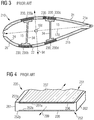
FIG 3 shows a cross-sectional view of an airfoil section of a conventionally knownrotor blade 210, hereinafter also referred to as theconventional blade 210, havingpultruded strips 235 stacked in spar caps 230 of theconventional blade 210. One of these structural elements, i.e. the conventionally knownpultruded strips 235 is schematically depicted inFIG 4 . The conventionally knownpultruded strip 235, hereinafter also referred to as theconventional strip 235 is defined by planar surfaces and generally resembles a longitudinally, i.e. along alongitudinal axis 299 of theconventional strip 235, elongated rectangular parallelepiped such as a bar or slab, and has a rectangular shaped cross-section when sectioned normally to thelongitudinal axis 299. Suchconventional strips 235 ofFIG 4 are stacked atop each other to form a stack of theconventional strips 235. The stack is then resin infused to form the conventional spar cap 230. - As shown in
FIG 3 , theconventional blade 210 includes ashell 21. Theshell 21 is generally made from two half shells i.e. aleeward shell 21a and awindward shell 21b both moulded generally from glass-fibre reinforced plastics. This is generally referred to as the 'butterfly blade' since it has twoseparate half shells complete shell 21 for example the twohalf shells shell 21. Alternatively, theblade 210 may include ashell 21 that is formed integrally i.e. theshell 21 does not have the twohalf shells shell 21 have a sandwich panel construction and comprise acore 22 of lightweight material e.g. polyurethane foam, PET foam, balsa wood, etc. sandwiched between inner and outer surfaces orfacesheets shell 21. Within theblade 210 is ablade cavity 15. Theblade 210 may include one or more spar caps 230, generally in pairs for example first pair of spar caps 230 namely spar caps 230a and 230b and second pairs of spar caps 230 namely spar caps 230c and 230d. Each pair of the spar caps 230 i.e. the spar caps 230a, 230b and the spar caps 230c and 230d are supported by ashear web 34, also referred to as theweb 34, which forms a generally known I-beam shape along with the spar caps 230. The spar caps 230a, 230b, 230c, 230d are generally embedded in theshell 21 either partially or completely. One spar cap 230 of each pair is embedded or integrated with theleeward shell 21a and the other spar cap 230 of the pair is embedded or integrated with thewindward shell 21b. - The spar caps 230 have a generally elongated rectangular parallelepiped shape such as a bar or slab, elongated in a span wise direction of the
blade 210, i.e. in other words the spar cap 230 has a rectangular cross section when sectioned perpendicular to the span of theblade 210. The conventionally known spar cap 230 is made up of the stack(s) of prefabricatedconventional strips 235 ofFIG 4 . Theconventional strips 235 are pultruded strips of carbon-fibre reinforced plastic and are substantially flat and have a rectangular cross-section. - During manufacturing of the turbine blade 210 a resin-infusion process is used. Various laminate layers of the
shell 21 are laid up, generally by hand-lay, in a mould cavity, theconventional strips 235 are then stacked where the spar caps 230 are to be formed i.e. interspersed between parts of the leeward and thewindward shells strips 235 of the stack and to infuse into the interstitial spaces between the laid up layers and between thestrips 235. Finally, the resin-infused layup is cured to harden the resin and bond the various laminate layers and thestrips 235 together and to each other to form theblade 210. - The
strips 235 described above have a relatively smooth and flat outer surface resulting from the pultrusion process used in manufacturing of thestrips 235. As a result, when thestrips 235 are stacked atop one another in the mould, there is very little space at the interfaces between thestrips 235 for allowing adequate amounts of resin to flow therein. The lack of resin in-between thestrips 235 results in poor bonding of thestrips 235 for example by forming kissing bonds. Improperly bondedstrips 235 pose increased risk of delamination occurring in the blade structure and this may lead to damage and compromise of the structural integrity of theturbine blade 235. The aforementioned problem is caused as a result of flat smooth outer surface of thestrips 235, whether pultruded or otherwise manufactured, which pack closely with the flat smooth surfaces of othersimilar strips 235 leaving little or no space for flow of resin during resin infusion. - To solve the aforementioned problem of inadequate space between the flat faced
strips 235 some recent techniques use roughening of the flat smooth surface of thestrip 235 for example by using peel-ply 236 as shown inFIG 4 , or by using other surface roughening techniques such as sandblasting, sanding, grinding, corona treatment, plasma treatment etc. These techniques require additional steps in the manufacturing process of theblade 210 and thus make the manufacturing process lengthier and resource intensive, for example requiring sanding equipment and manpower, etc. - Thus in a nutshell the stacking of the
conventional strips 235 during manufacturing of the spar caps 230 leaves inadequate amount of interstitial space between thestrips 235 causing problem in resin infusion into these interstitial space between thestrips 235. Therefore there exists a need for a technique that ensures adequate amount of interstitial space between the strips that are used to stack with each other to form the spar caps for wind turbine rotor blades, and thus at least partially obviating the problem of inadequate resin infusion and/or resin excess into these interstitial spaces between the stacked strips. - The object of the present invention is to provide a technique that ensures adequate amount of interstitial space between the strips stacked with each other to form the spar caps for wind turbine rotor blades, and thus allowing adequate resin infusion into these interstitial spaces between the stacked strips.
- The abovementioned object is achieved by a pultruded fibrous composite strip according to
claim 1 of the present technique, by a spar cap according toclaim 12 of the present technique, by a wind turbine rotor blade according toclaim 13 of the present technique, and by a method for making a spar cap according toclaim 14 of the present technique. Advantageous embodiments of the present technique are provided in dependent claims. - In a first aspect of the present technique a pultruded fibrous composite strip is presented. The pultruded fibrous composite strip, hereinafter also referred to as the strip is for stacking with one or more similar strips to form a spar cap of a wind turbine rotor blade, hereinafter also referred to as the blade. The strip has a substantially constant cross-section defined by first and second mutually opposed and longitudinally extending sides, and by first and second longitudinal edges. The first side includes a first abutment surface and the second side includes a second abutment surface. At least one of the first abutment surface and the second abutment surface has a corrugated profile such that a plurality of longitudinally extending grooves are defined on the first abutment surface and/or the second abutment surface. When the strip is stacked with similar strips, in preparation of resin infusion and subsequent curing of the resin to bond the strip with the other similar strips to form the spar cap, the grooves on the first and/or the second abutment surface of the strip facilitate flow of resin, and thereby better resin infusion between the strips of the stack is achieved compared to conventionally known strips with flat or planar abutment surfaces.
- The pultruded fibrous composite strip is a pultruded strip of composite material having unidirectional fibers (UD) reinforcement The pultruded strips have structural fibers, generally longitudinally running along the strip and hence unidirectional, made of glass, carbon, aramid and/or basalt, while the matrix that keeps the fibers together in the strip and protects them from external agents may be, but not limited to, epoxy, vinylester, polyurethane, polyester, etc.
- The profile of the abutment surface means an outline, silhouette, contour, shape of the surface. The profile of the abutment surface is represented by a curvature of the surface when observed holistically for the surface.
- In an embodiment of the strip, the corrugated profile has a wave shape in a transverse direction of the strip. The transverse direction of the strip extends between the first and the second longitudinal edges of the strip. The transverse direction of the strip is perpendicular to a longitudinal direction of the strip. The wave shape ensures that corrugations are spread across the abutment surface.
- In another embodiment of the strip, the wave shape is a symmetric waveform, i.e. the wave shape resembles a symmetric waveform such as symmetric periodic waveform for example a sinusoidal waveform. Thus the corrugation is spread evenly over the abutment surface.
- In another embodiment of the strip, amplitude of the wave shape is between 100 µm (micrometer) and 1000 µm. The amplitude of the wave shape is a distance between a lowest point of a groove and a highest point of a ridge, measured along a thickness of the strip, i.e. measured along a direction perpendicular to the transverse direction of the strip. Thus the grooves are deep enough to ensure proper resin flow through the grooves but not too deep to limit the resin within the groove i.e. in other words the grooves facilitate the flow of resin during resin infusion but then are over-filled and allow flow of resin, in the transverse direction of the strip, to areas of the abutment surfaces adjacent to the grooves.
- In another embodiment of the strip, wavelength of the wave shape is between 2 mm (millimeter) and 50 mm. The wavelength of the wave shape is a distance between the two consecutive grooves or between two consecutive ridges formed adjoining a given groove.
- In another embodiment of the strip, the first abutment surface and the second abutment surface both have corrugated profiles. The first abutment surface has a first wave shape, and the second abutment surface has a second wave shape, both the first and the second wave shapes extend or are oriented in the transverse direction of the strip, i.e. direction of the strip that extends between the first and the second longitudinal edges of the strip and is perpendicular to a longitudinal direction of the strip. In this embodiment of the strip, the first and the second wave shapes are identical. Thus stacking of the strips is compact.
- In another embodiment of the strip, the first abutment surface and the second abutment surface both have corrugated profiles. The first abutment surface has a first wave shape, and the second abutment surface has a second wave shape, both the first and the second wave shapes extend or are oriented in the transverse direction of the strip, i.e. direction of the strip that extends between the first and the second longitudinal edges of the strip and is perpendicular to a longitudinal direction of the strip. In this embodiment of the strip, the first and the second wave shapes are non-identical, i.e. the first and the second wave shapes differ in amplitude and/or wavelength. Thus the grooves on the abutment surface of a given strip are not completely closed or filled up by the ridges of the abutment surface of an adjacent strip in the stack.
- In another embodiment of the strip, one from the first abutment surface and the second abutment surface has the corrugated profile and the other has a planar surface. The strips when stacked may be stacked in such a way that the abutment surface of a given strip having the corrugated profile faces the abutment surface of an adjacent strip having the planar surface, and vice versa. Thus the grooves on the abutment surface of the given strip are not closed or filled up by the abutment surface of the adjacent strip in the stack.
- In another embodiment of the strip, the first abutment surface and/or the second abutment surface having the corrugated profile, i.e. the abutment surface or the abutment surfaces having the corrugated profile according to the present technique, include or includes one or more trenches formed therein and extending between at least two adjacent longitudinally extending grooves of the plurality of longitudinally extending grooves present on the abutment surface. The one or more trenches are configured to fluidly connect the two adjacent longitudinally extending grooves i.e. the trenches allow or facilitate flow of resin between the two adjacent grooves. The trenches may have different orientations with respect to the grooves for example the trenches may oriented at 90 degree, 45 degree, etc with respect to the grooves.
- In another embodiment of the strip, the strip includes a first peel-ply layer on the first abutment surface and/or a second peel-ply layer on the second abutment surface. The peel-ply layer at least partially covers the abutment surface on which the peel-ply layer is present. The peel-ply layer is present on the abutment surface(s) having the corrugated profile. The peel-ply or the peel-plies may be removed before stacking of the strips and before performing resin infusion and the removal of the peel-ply or the peel-plies provides a roughened surface on the abutment surface from where the peel-ply has been removed.
- In a second aspect of the present technique, a spar cap for a wind turbine rotor blade is presented. The spar cap includes a plurality of pultruded fibrous composite strips stacked with one or more similar strips to form a stack of the strips. Each of the strips is as described hereinabove for the first aspect of the present technique. In the stack, the strips are oriented such that one of the abutment surfaces, i.e. either the first or the second abutment surface of the strip, of one of the strips of the stack faces one of the abutment surfaces of an adjacent strip, i.e. faces either the first or the second abutment surface of the adjacent strip of the stack. The spar cap with such strips has better resin bonding compared to the conventional spar caps without strips with corrugated profiles.
- In a third aspect of the present technique, a wind turbine rotor blade is presented. The wind turbine rotor blade, hereinafter also referred to as the blade, has at least one spar cap extending longitudinally in a span-wise direction of the blade. The spar cap includes a plurality of pultruded fibrous composite strips stacked with one or more similar strips. Each of the strips is according to the first aspect of the present technique as described hereinabove. Each of the strips is oriented such that the first and the second sides of the strip longitudinally extend along the span-wise direction of the blade and are spaced apart in a flap-wise direction of the blade, and the first and the second edges of the strip longitudinally extend along the span-wise direction of the blade and are spaced apart in a chordwise direction of the blade. The blade having the spar cap according to the present technique has better resin bonding between the constituent strips of the spar cap as compared to the conventional spar caps without strips with corrugated profiles.
- In a fourth aspect of the present technique a method for making a spar cap for a wind turbine rotor blade is presented. In the method of the present technique, a plurality of pultruded fibrous composite strips is provided. Each of the strips is according to the first aspect of the present technique described hereinabove. The strips are then stacked in a mould to form a stack of the strips. The strips are stacked such that in the stack so formed one of the abutment surfaces, i.e. either the first abutment surface or the second abutment surface of one of the strips of the stack faces one of the abutment surfaces, i.e. either the first abutment surface or the second abutment surface, of an adjacent strip of the stack to define longitudinally extending resin flow channels, thereinbetween. Each of the resin flow channels includes at least one of longitudinally extending grooves defined on one of the abutment surfaces facing each other in the stack. Thereafter, in the method, resin is supplied to the stack. The resin is caused to infiltrate into the longitudinally extending resin flow channels. Finally in the method, the resin is cured to bond the adjacent strips together.
- In an embodiment of the method, one or more of the strips include a first peel-ply layer at least partially covering the first abutment surface and/or a second peel-ply layer at least partially covering the second abutment surface. The peel-ply layer is present on the surface having the corrugated profile. In the method the first and/or the second peel plies are removed from their respective abutment surfaces before stacking the strips in the mould to form the stack of the strips.
- The above mentioned attributes and other features and advantages of the present technique and the manner of attaining them will become more apparent and the present technique itself will be better understood by reference to the following description of embodiments of the present technique taken in conjunction with the accompanying drawings, wherein:
- FIG 1
- schematically depicts a wind turbine having a wind turbine rotor blade in which a spar cap made from pultruded fibrous composite strips of the present technique may be incorporated;
- FIG 2
- schematically depicts the wind turbine rotor blade in which the spar cap made from the pultruded fibrous composite strips of the present technique may be incorporated;
- FIG 3
- depicts a cross-sectional view of an airfoil of a conventionally known turbine blade having a conventionally known spar cap made from conventionally known pultruded strips;
- FIG 4
- depicts a conventionally known pultruded strip used to manufacture the conventionally known spar cap;
- FIG 5
- schematically depicts a perspective view of an exemplary embodiment of a pultruded fibrous composite strips of the present technique;
- FIG 6
- schematically depicts a cross-sectional view of another exemplary embodiment of the pultruded strip of the present technique;
- FIG 7
- schematically depicts a cross-sectional view of the exemplary embodiment of the pultruded strip of
FIG 5 depicting exemplary wave shapes of first and second abutment surfaces of the strip of the present technique; - FIG 8
- schematically depicts a cross-sectional view of the strip of
FIG 7 depicting a scheme of measurements of the wave shapes; - FIG 9
- schematically depicts a cross-sectional view of another exemplary embodiment of the strip of the present technique depicting exemplary non-identical wave shapes of the first and the second abutment surfaces of the strip of the present technique;
- FIG 10
- schematically depicts a cross-sectional view of yet another exemplary embodiment of the pultruded strip of the present technique depicting an exemplary wave shape of the first abutment surface and depicting planar surfaces as part of the second abutment surface of the strip of the present technique;
- FIG 11
- schematically depicts a cross-sectional view of further exemplary embodiment of the pultruded strip of the present technique depicting an exemplary wave shape of the first abutment surface and depicting planar second abutment surface of the strip of the present technique;
- FIG 12
- schematically depicts a cross-sectional view of an exemplary embodiment of the pultruded strip of the present technique depicting a first peel-ply layer and a second peel-ply layer on the first and the second abutment surfaces, respectively, in accordance with aspects of the present technique;
- FIG 13
- schematically depicts an exemplary embodiment of two pultruded fibrous composite strips of the present technique stacked with each other to manufacture the spar cap of the present technique;
- FIG 14
- schematically depicts another exemplary embodiment of two pultruded fibrous composite strips of the present technique stacked with each other to manufacture the spar cap of the present technique;
- FIG 15
- schematically depicts yet another exemplary embodiment of two pultruded fibrous composite strips of the present technique stacked with each other to manufacture the spar cap of the present technique;
- FIG 16
- schematically depicts a further exemplary embodiment of two pultruded fibrous composite strips of the present technique stacked with each other to manufacture the spar cap of the present technique;
- FIG 17
- schematically depicts a perspective view of an exemplary embodiment of the strip of the present technique having a trench connecting two adjacent grooves in the strip;
- FIG 18
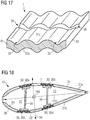
- depicts a cross-sectional view of an exemplary embodiment of an airfoil of the wind turbine rotor blade of
FIG 2 having a spar cap made from the strips of the present technique; and - FIG 19
- presents a flow chart depicting a method for making a spar cap for a wind turbine rotor blade in accordance with aspects of the present technique.
- Hereinafter, above-mentioned and other features of the present technique are described in details. Various embodiments are described with reference to the drawing, wherein like reference numerals are used to refer to like elements throughout. In the following description, for the purpose of explanation, numerous specific details are set forth in order to provide a thorough understanding of one or more embodiments. It may be noted that the illustrated embodiments are intended to explain, and not to limit the invention. It may be evident that such embodiments may be practiced without these specific details.
- It may be noted that in the present disclosure, the terms "first", "second", "third" etc. are used herein only to facilitate discussion, and carry no particular temporal or chronological significance unless otherwise indicated.
-
FIG 1 shows an exemplary embodiment of awind turbine 100 of the present technique. Thewind turbine 100 includes atower 120, which is mounted on a fundament (not shown). Anacelle 122 is mounted on top of thetower 120 and rotatable with regard to thetower 120 by means of a yawangle adjustment mechanism 121 such as yaw bearings and yaw motors. The yawangle adjustment mechanism 121 functions to rotate thenacelle 122 around a vertical axis (not shown) referred to as a yaw axis, which is aligned with the longitudinal extension of thetower 120. The yawangle adjustment mechanism 121 rotates thenacelle 122 during operation of thewind turbine 100 to ensure that thenacelle 122 is appropriately aligned with the current wind direction to which thewind turbine 100 is subjected. - The
wind turbine 100 further includes arotor 110 having at least arotor blade 10, and generally threerotor blades 10, although in the perspective view ofFIG 1 only tworotor blades 10 are visible. One of therotor blades 10 is schematically depicted inFIG 2 . Therotor 110 is rotatable around arotational axis 110a. Therotor blades 10, hereinafter also referred to as theblades 10 or as theblade 10 when referring to one of theblades 10, are generally mounted at adriving collar 112, also referred to as ahub 112. Thehub 112 is mounted rotatable with regard to thenacelle 122 by means of a main bearing (not shown). Thehub 112 is rotatable about therotational axis 110a. Each of theblades 10 extends radially with respect to therotational axis 110a and has anairfoil section 20. - In between the
hub 112 and each of therotor blades 10, is provided ablade adjustment mechanism 116 in order to adjust the blade pitch angle of theblade 10 by rotating therespective blade 10 about a longitudinal axis (not shown) of theblade 10. The longitudinal axis of each of theblade 10 is aligned substantially parallel with the longitudinal extension of therespective blade 10. Theblade adjustment mechanism 116 functions to adjust blade pitch angles of therespective blade 10. - The
wind turbine 100 includes amain shaft 125 that rotatably couples therotor 110, particularly thehub 112, to agenerator 128 housed within thenacelle 122. Thehub 112 is connected to a rotor of thegenerator 128. In an exemplary embodiment (not shown) of thewind turbine 100, thehub 112 is connected directly to the rotor of thegenerator 128, thus thewind turbine 100 is referred to as a gearless, directdrive wind turbine 100. As an alternative, as shown in the exemplary embodiment ofFIG 1 , thewind turbine 100 includes agear box 124 provided within thenacelle 122 and themain shaft 125 connects thehub 112 to thegenerator 128 via thegear box 124, thereby thewind turbine 100 is referred to as a gearedwind turbine 100. Thegear box 124 is used to convert the number of revolutions of therotor 110 into a higher number of revolutions of themain shaft 125, and consequently of the rotor of thegenerator 128. Furthermore, abrake 126 is provided in order to stop the operation of thewind turbine 100 or to reduce the rotational speed of therotor 110 for instance in case of a very strong wind and/or in case of an emergency. - The
wind turbine 100 further includes acontrol system 150 for operating thewind turbine 100 at desired operational parameters, for example at a desired yaw angle, with a desired blade pitch, at a desired rotational speed of therotor 110, and so on and so forth. The controlling and/or adjusting of the operational parameters are performed to obtain an optimized power generation under the existent conditions for example under existent wind conditions and other weather conditions. - The
wind turbine 100 may further include different sensors for example arotational speed sensor 143, apower sensor 144,angle sensors 142, etc that provide inputs to thecontrol mechanism 150 or other components of thewind turbine 100 to optimize operation of thewind turbine 100. - Furthermore as shown in
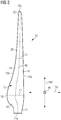
FIG 2 , therotor blade 10 includes aroot section 11 having aroot 11a and anairfoil section 20. Generally, therotor blade 10 includes a transition section 90 in between theroot section 11 and theairfoil section 20. Theairfoil section 20, hereinafter also referred to as theairfoil 20, includes atip section 12 having atip 12a. Theroot 11a and thetip 12a are separated by aspan 16, of therotor blade 10, which follows the shape of therotor blade 10. A direction along or parallel to thespan 16 is referred to asspan-wise direction 16d. Thetip section 12, including thetip 12a therein, extends from thetip 121 towards theroot 11a up to a span-wise position of approx 33.3% (percent), i.e. one third of the total length of theblade 10, as measured from thetip 12a. Thetip 12a extends within thetip section 12 towards theroot 11a up to a span-wise position of approx. one meter. Therotor blade 10 includes aleading edge section 14 having aleading edge 14a, and a trailingedge section 13 having a trailingedge 13a. The trailingedge section 13 surrounds the trailingedge 13a. Similarly, theleading edge section 14 surrounds theleading edge 14a. - At each span-wise position perpendicular to the
span 16, achord line 17 that connects theleading edge 14a and the trailingedge 13a can be defined. A direction along or parallel to thechord line 17 is referred to aschord-wise direction 17d.FIG 3 depicts twosuch chord lines 17 at two different span-wise positions. Furthermore a direction mutually perpendicular to thespan-wise direction 16d and to thechord-wise direction 17d is referred to as aflap-wise direction 9d. Therotor blade 10 has ashoulder 18 that is a section of therotor blade 10 where thechord line 17 has maximum chord length, i.e. in example ofFIG 2 at thechord line 17 that is depicted towards theroot 11a. - In the
wind turbine 100, one or more of theblades 10 include one or more spar caps 30 shown inFIG 18 according to the present technique. In accordance with the present technique, the spar cap 30 of the present technique includes a component of such a spar cap 30 i.e. apultruded strip 1 as shown inFIGs 5 to 18 . The technique also presents amethod 500 for making such a spar cap 30 using thepultruded strip 1 of the present technique as shown inFIG 19 . Hereinafter,FIGs 5 to 19 in combination withFIGs 1 and2 have been referred to further explain the present technique. It may be noted that therotor blade 10 of the present technique differs from the conventionally knownrotor blade 210 as shown inFIG 3 only for the spar cap 30 and thepultruded strips 1, and other components of therotor blade 10 are same as described hereinabove with reference toFIG 3 for theconventional blade 210, for example theweb 34, the leeward andwindward shells pultruded strip 1 as opposed to the structure of theconventional strip 235, and in the spar cap 30 resulting from the use of thepultruded strips 1 as opposed to the spar caps 230 formed from the conventional strips 235. -
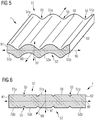
FIGs 5 and 6 show exemplary embodiments of thepultruded strip 1 of the present technique. As aforementioned, thepultruded strips 1, hereinafter also referred to as thestrip 1 are pultruded unidirectional fibrous composite strips. Thestrip 1, depicted inFIGs 5 to 18 is a pultruded strip of composite material having unidirectional fibers (UD) reinforcement i.e. thestrips 1 have structural fibers, generally longitudinally running along the strip and hence unidirectional, made of glass, carbon, aramid and/or basalt, while the matrix that keeps the fibers together in thestrip 1 and protects the fibers from external agents may be, but not limited to, epoxy, vinylester, polyurethane, polyester, etc. Each of thestrips 1 are formed by pultrusion, a continuous process similar to extrusion, in which fibers e.g. glass-fibers or carbon-fibers are pulled through a supply of liquid resin i.e. through the material of the matrix that keeps the fibers together, and through dies that shape thestrip 1 to the shape according to the present technique. The resin i.e. the matrix material is then cured, for example by heating in an open chamber, or by employing heated dies that cure the resin as thestrip 1 is pultruded. - The
strip 1 is used to form the spar cap 30 ofFIG 18 by stacking thestrip 1 with one or moresimilar strips 1 to form the spar cap 30 of therotor blade 10 of thewind turbine 100. As shown inFIG 5 , thestrip 1 has alongitudinal axis 99 extending generally in the direction in which thestrip 1 was pultruded when manufactured, and which is also the direction along which the fibers (not shown) of thestrip 1 extend. Thestrip 1, as depicted from a cross-section of thestrip 1 as shown inFIG 6 , and as can be inferred fromFIG 5 , has afirst side 51 and asecond side 52 opposite to thefirst side 51, and afirst edge 61 and asecond edge 62 opposite to thefirst edge 61. Thestrip 1 has a substantially constant cross-section, i.e. thestrip 1 maintains its cross-sectional shape and dimensions at positions along thelongitudinal axis 99. Thestrip 1 is defined by the first and the second mutually opposed and longitudinally extendingsides longitudinal edges sides edges longitudinal axis 99 of thestrip 1. - The
first side 51 includes afirst abutment surface 51a. Thefirst abutment surface 51a may be the entire surface of thefirst side 51 i.e. covering the entire expanse between the first and the second edges 61, 62. Alternatively, thefirst abutment surface 51a may be a substantial part of the entire surface of thefirst side 51 and may be limited by a border or peripheral region or peripheral surface region of thefirst side 51 towards the first and the second edges 61, 62, or in other words, the surface of thefirst side 51 has at least two regions - namely the twoperipheral regions 51p and thefirst abutment surface 51a sandwiched between theperipheral regions 51p. The width of each of theperipheral region 51p i.e. expanse of theperipheral region 51p, as measured along thefirst side 51 and perpendicular to thelongitudinal axis 99 may be between 2% and 10% of a distance between the first and thesecond edge first side 51 and perpendicular to thelongitudinal axis 99. The advantage of having theperipheral regions 51p is that presence of theperipheral regions 51p allows incorporation of a peel ply (not shown inFIGs 5 and 6 ) on the surface offirst side 51 during the pultrusion process. When a peel ply is incorporated on the surface offirst side 51 during the pultrusion process, the area or region of the surface of thefirst side 51 covered by the peel-ply is thefirst abutment surface 51a, and the area or region of the surface of thefirst side 51 not covered by the peel-ply is the firstperipheral regions 51p. When a peel ply is incorporated on the surface offirst side 51, a surface of the peel ply is flush with the firstperipheral regions 51p. - Similarly, the
second side 52 includes asecond abutment surface 52a. Thesecond abutment surface 52a may be the entire surface of thesecond side 52 i.e. covering the entire expanse between the first and the second edges 61, 62. Alternatively, thesecond abutment surface 52a may be a substantial part of the entire surface of thesecond side 52 and may be limited by a border or peripheral region or peripheral surface region of thesecond side 52 towards the first and the second edges 61, 62, or in other words, the surface of thesecond side 52 has at least two regions - namely the twoperipheral regions 52p and thesecond abutment surface 52a sandwiched between theperipheral regions 52p. The width of each of theperipheral region 52p i.e. expanse of theperipheral region 52p, as measured along thesecond side 52 and perpendicular to thelongitudinal axis 99 may be between 2% and 10% of a distance between the first and thesecond edge second side 52 and perpendicular to thelongitudinal axis 99. The advantage of having theperipheral regions 52p is that presence of theperipheral regions 52p allows incorporation of a peel ply (not shown inFIGs 5 and 6 ) on the surface ofsecond side 52 during the pultrusion process. When a peel ply is incorporated on the surface ofsecond side 52 during the pultrusion process, the area or region of the surface of thesecond side 52 covered by the peel-ply is thesecond abutment surface 52a, and the area or region of surface of thesecond side 52 not covered by the peel-ply is the secondperipheral regions 52p. When a peel ply is incorporated on the surface ofsecond side 52, a surface of the peel ply is flush with the secondperipheral regions 52p. - According to aspects of the present technique, at least one of the
first abutment surface 51a and thesecond abutment surface 52a has a corrugated profile, i.e. shaped into a series ofparallel ridges 56 andgrooves 55. As a result of the corrugated profile, a plurality of longitudinally extendinggrooves 55 are defined on thefirst abutment surface 51a and/or thesecond abutment surface 52a i.e. on the abutment surface that has the corrugated profile - which may be both the abutment surfaces 51a and 52a, or one of the abutment surfaces i.e. either 51a or 52a. Theridges 56 may be hill-shaped as shown inFIG 5 or may be flat as shown inFIG 6 . - The
groove 55 may be understood as a pit, trench, channel, canal or valley that extends along thelongitudinal axis 99 and on theabutment surface strip 1 is stacked withsimilar strips 1, as later depicted inFIGs 13 to 16 , in preparation of resin infusion and subsequent curing of the resin to bond thestrip 1 with the othersimilar strips 1 to form the spar cap 30, thegrooves 55 on the first and/or thesecond abutment surfaces strip 1 facilitate flow of resin, and thereby better resin infusion between thestrips 1 of the stack is achieved compared to conventionally knownstrips 235 with flat orplanar abutment surfaces second sides second edges conventional strip 235 shown inFIG 4 . -
FIG 5 andFIG 7 schematically depict an embodiment of thestrip 1 in which the corrugated profile has a wave shape in atransverse direction 96 of thestrip 1. Thetransverse direction 96 of the strip extends between the first and the secondlongitudinal edges transverse direction 96 of thestrip 1 is perpendicular to the longitudinal direction oraxis 99 of thestrip 1.FIG 7 shows two axes namelyaxis 96a andaxis 96b that extend along thetransverse direction 96 of thestrip 1. As can be seen in the depiction ofFIG 7 , thefirst abutment surface 51a has the corrugated profile in form of the wave shape, and thesecond abutment surface 52a also has the corrugated profile in form of the wave shape. Thefirst abutment surface 51a, when observed in the direction of the longitudinal axis depicts the wave shape. Theaxis 96a is represented only for the purpose of depiction of the wave shape of thefirst abutment surface 51a. Similarly, thesecond abutment surface 52a, when observed in the direction of the longitudinal axis depicts the wave shape. Theaxis 96b is represented only for the purpose of depiction of the wave shape of thesecond abutment surface 52a. - In another embodiment of the strip, as also depicted in
FIG 7 , the wave shape is a symmetric waveform, i.e. the wave shape resembles a symmetric waveform such as symmetric periodic waveform for example a sinusoidal waveform. Thus the corrugation is spread evenly over theabutment surface grooves 55 formed on the abutment surfaces 51a, 52a as shown inFIGs 5 to 18 are provided as way of explanation and not as a way of limitation. It may also be noted that the number ofgrooves 55 formed on theabutment surface -
FIG 8 provides a scheme of measurements for the corrugated profile when present in form of a wave shape, and particularly when present in form of the sinusoidal waveform. As shown inFIG 8 , the wave shape has amplitude A1 for the waveform on thefirst abutment surface 51a and/or amplitude A2 for the waveform on thesecond abutment surface 52a. Similarly, the wave shape has wavelength λ1 for the waveform on thefirst abutment surface 51a and/or wavelength λ2 for the waveform on thesecond abutment surface 52a. In general the amplitude A, i.e. either A1 and/or A2, is between 100 µm (micrometer) and 1000 µm. Independently of the aforementioned range for the amplitude A, in general the wavelength λ, i.e. either λ1 and/or λ2, of the wave shape is between 2 mm and 50 mm. The wavelength λ of the wave shape is a distance between the twoconsecutive grooves 55 or between the tworidges 56 formed adjoining a givengroove 55. The amplitude A of the wave shape is a distance between a lowest point of a givengroove 55 and a highest point of an adjoiningridge 56, measured along a thickness of thestrip 1, i.e. measured along adirection 97, as shown inFIG 5 , perpendicular to thetransverse direction 96 of thestrip 1 and perpendicular to thelongitudinal axis 99 of thestrip 1. - As shown in
FIGs 7, 8, and 9 in embodiments of thestrip 1, thefirst abutment surface 51a and thesecond abutment surface 52a both have corrugated profiles in form of the first wave shape and the second wave shape, respectively. Both the first and the second wave shapes extend or are oriented in thetransverse direction 96 of thestrip 1, i.e. direction of the strip that extends between the first and the secondlongitudinal edges strip 1 and is perpendicular to thelongitudinal direction 99 of thestrip 1. In an embodiment of thestrip 1, as shown inFIGs 7 and 8 the first and the second wave shapes are identical i.e. the amplitudes A1 and A2 are substantially the same and the wavelengths λ1 and λ2 are substantially the same. In an alternate embodiment of thestrip 1, as shown inFIG 9 , the first and the second wave shapes are non-identical i.e. the first and the second wave shapes differ from each other in wavelength and/or amplitude (not shown inFIG 9 ). - As shown in
FIG 10 , in another embodiment of thestrip 1, thefirst abutment surface 51a and thesecond abutment surface 52a have the corrugated profile, however, one or both of the abutment surfaces 51a, 52a include planar surfaces P in between twoadjoining grooves 55. As shown inFIG 11 , in another embodiment of thestrip 1, one from thefirst abutment surface 51a and thesecond abutment surface 52a has the corrugated profile and the other has a planar surface P and is thus without corrugated profile. - As shown in
FIG 17 , in an embodiment of thestrip 1, thefirst abutment surface 51a and/or thesecond abutment surface 52a having the corrugated profile also includes one ormore trenches 58 formed therein. AlthoughFIG 17 depicts only onesuch trench 58, it is well within the scope of the present technique that a plurality ofsuch trenches 58 are formed on theabutment surface trenches 58 extends between at least twoadjacent grooves 55. Thetrenches 58 are pits, canals, channels, or valleys formed on theabutment surface adjacent grooves 55 so establishing fluid communication, i.e. being fluidly connected, between theadjacent grooves 55 i.e. thetrench 58 allow or facilitate flow of resin between the twoadjacent grooves 55. In a non-depicted embodiment thetrenches 58 extend perpendicular to thegrooves 55. -
FIG 12 depicts yet another embodiment of thestrip 1. In this embodiment thestrip 1 includes a first peel-ply layer 36 on thefirst abutment surface 51a and/or a second peel-ply layer 38 on thesecond abutment surface 52a. The peel-ply layer 36,38 at least partially covers theabutment surface ply layer 36,38 is present. Thesurface 37 of thepeel ply layer 36,38 is flush with the surface of theperipheral region sides strip 1. -
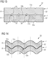
FIGs 13 to 16 show stacks 32 formed by placing thestrip 1 on top of anotherstrip 1. It may be noted that directional terminology, such as 'top', 'bottom', 'front', 'back' etc., is used inFIGs 13 to 16 and in other accompanying FIGs of the present technique with reference to the orientation of the FIG(s) being described. The components of the invention can be positioned in a number of different orientations. As such, the directional terminology is used for purposes of illustration and is in no way limiting. For example the stacking of thestrips 1 may be side by side instead of on top of one another. It may also be noted that although in thestacks 32 only twostrips 1 are depicted inFIGs 13 to 16 , in general the number ofstrips 1 in thestacks 32 are greater, for example between four and twelve, or more. The number ofstrips 1 to be stacked in thestack 32 depends on numerous factors for example, thickness of thestrips 1, desired thickness of the spar cap 30, etc. Thestack 32 ofFIG 13 shows twoidentical strips 1 ofFIG 6 stacked. Thestack 32 ofFIG 14 shows twoidentical strips 1 ofFIG 5 and7 stacked. Thestack 32 ofFIG 15 shows twonon-identical strips 1 stacked. The stack ofFIG 16 shows twoidentical strips 1 stacked but each of the stacked strip is has non-identical waveforms on itsrespective abutment surfaces FIGs 13 to 16 , as a result of thegrooves 55 present on the abutment surfaces 51a, 52a, when thestrips 1 are stacked,resin flow channels 59 are defined between the adjacent strips 1. Theresin flow channels 59 include one or more of thegrooves 55 of one or both of the adjacent strips 1. Theresin flow channels 59 also extend longitudinally between the surfaces of theadjacent strips 1 and facilitate resin flow. -
FIG 18 , in comparison withFIG 3 , depictsrotor blade 10 having spar caps 30 of the present technique. Instead of the conventional spar caps 230a, 230b, 230c, 230d are the spar caps 30a, 30b, 30c, 30d of the present technique. The spar cap 30 includes a plurality ofstrips 1 stacked with one or moresimilar strips 1. Each of thestrips 1 is as described hereinabove with respect toFIGs 5 to 12 andFIG 17 , and are stacked for example as described forFIGs 13 to 16 . Thestrips 1 are oriented such that one of the abutment surfaces 51a, 52a i.e. either the first or thesecond abutment surface strip 1 faces one of the abutment surfaces 51a, 52a of anadjacent strip 1, i.e. faces either the first or thesecond abutment surface adjacent strip 1. The first and thesecond sides flap-wise direction 9d. The first and the second edges 61, 62 are spaced apart in thechord-wise direction 17d. The first and thesecond sides strips 1 extend longitudinally along thespan-wise direction 16d. -
FIG 19 depicts a flow chart showing themethod 500 for making the spar cap 30, i.e. the one or more of the spar caps 30a, 30b, 30c, 30d, for the windturbine rotor blade 10. In themethod 500, in a step 510 a plurality of thestrips 1 is provided. Each of thestrips 1 is as described hereinabove in reference toFIGs 5 to 12 . Thestrips 1 are then stacked in a mould to form a stack of the strips. In themethod 500, after thestep 510 in astep 530, thestrips 1 are stacked as described hereinabove in reference toFIGs 13 to 16 , thus defining theresin flow channels 59 in-between the stacked strips 1. After completion of this stage of themethod 500, the mould has thestack 32 of thestrips 1 and has components that are placed to form parts of theshell 21 of theblade 10. Thereafter, subsequent to thestep 530 in themethod 500, in astep 540 resin is supplied to thestack 32. The resin flow in thestep 540 may be achieved by Vacuum Assisted Resin Transfer Molding (VARTM) process. Finally in themethod 500, in astep 550 the resin is cured to bond theadjacent strips 1 together. - An embodiment of the
method 500, when thestrips 1 used for themethod 500 include the first and/or the second peel-ply layers 36, 38 as described hereinabove in reference toFIG 17 , includes astep 520 in which the first and/or the second peel plies 36, 38 are removed from theirrespective abutment surfaces step 530 is performed. - It may be noted that the
strips 1 of the present technique are used for thewind turbine blades 10 that have the so-called 'structural shell design' as shown inFIG 18 in which the spar caps 30a, 30b, 30c, 30d are integrated within the structure of theouter shell 21. Furthermore, the number of spar caps 30a, 30b, 30c, 30d depicted inFIG 18 are for exemplary purposed only, and it may be appreciated by one skilled in the art that theblade 10 of the present technique may have two spar caps 30 i.e. only one pair of the spar caps 30, or may have more than four spar caps 30, for example six spar caps 30 forming three distinct pairs of the spar caps 30. - It may further be noted that description of
FIG 3 and its comparison withFIG 18 represents a 'butterfly blade' construction. However, the present technique is also applicable to the well known 'integral blade' construction of Siemens, where unlike butterfly blade construction the leeward and windward shells are not separately manufactured. In the integral blade construction the entire shell is manufactured in one-part as an integral shell and thus does not have a separately manufactured leeward and windward side. - While the present technique has been described in detail with reference to certain embodiments, it should be appreciated that the present technique is not limited to those precise embodiments. Rather, in view of the present disclosure which describes exemplary modes for practicing the invention, many modifications and variations would present themselves, to those skilled in the art without departing from the scope and spirit of this invention. The scope of the invention is, therefore, indicated by the following claims rather than by the foregoing description. All changes, modifications, and variations coming within the meaning and range of equivalency of the claims are to be considered within their scope.
Claims (15)
- A pultruded fibrous composite strip (1) for stacking with one or more similar strips (1) to form a spar cap (30) of a wind turbine rotor blade (10), the strip (1) being of substantially constant cross-section defined by first and second mutually opposed and longitudinally extending sides (51,52) and by first and second longitudinal edges (61,62), the first and second sides (51,52) comprising, respectively, first and second abutment surfaces (51a,52a),
charachterized in that,
at least one of the first abutment surface (51a) and the second abutment surface (52a) has a corrugated profile such that a plurality of longitudinally extending grooves (55) are defined on the first abutment surface (51a) and/or the second abutment surface (52a). - The strip (1) according to claim 1, wherein the corrugated profile has a wave shape in a transverse direction (96) extending between the first and the second longitudinal edges (61,62) and wherein the transverse direction (96) of the strip (1) is perpendicular to a longitudinal direction (99) of the strip (1).
- The strip (1) according to claim 2, wherein the wave shape is a symmetric waveform.
- The strip (1) according to claim 3, wherein the symmetric waveform is a sinusoidal waveform.
- The strip (1) according to any of claims 2 to 4, wherein amplitude (A) of the wave shape is between 100 µm and 1000 µm.
- The strip (1) according to any of claims 2 to 5, wherein wavelength (λ) of the wave shape is between 2 mm and 50 mm.
- The strip (1) according to any of claims 1 to 6, wherein the first abutment surface (51a) and the second abutment surface (52a) both have corrugated profiles having a first wave shape and a second wave shape, respectively, in a transverse direction (96) extending between the first and the second longitudinal edges (61,62) and wherein the transverse direction (96) of the strip (1) is perpendicular to a longitudinal direction (99) of the strip (1) and wherein the first and the second wave shapes are identical.
- The strip (1) according to any of claims 1 to 6, wherein the first abutment surface (51a) and the second abutment surface (52a) both have corrugated profiles having a first wave shape and a second wave shape, respectively, in a transverse direction (96) extending between the first and the second longitudinal edges (61,62) and wherein the transverse direction (96) of the strip (1) is perpendicular to a longitudinal direction (99) of the strip (1) and wherein the first and the second wave shapes differ in amplitude (A) and/or wavelength (λ).
- The strip (1) according to any of claims 1 to 6, wherein one of the first abutment surface (51a) and the second abutment surface (52a) has the corrugated profile and other of the first abutment surface (51a) and the second abutment surface (52a) has a planar surface.
- The strip (1) according to any of claims 1 to 9, wherein the first abutment surface (51a) and/or the second abutment surface (52a) having the corrugated profile comprises one or more trenches (58) formed therein and extending between at least two adjacent longitudinally extending grooves (55) of the plurality of longitudinally extending grooves (55), wherein the one or more trenches (58) are configured to fluidly connect the two adjacent longitudinally extending grooves (55).
- The strip (1) according to any of claims 1 to 10, wherein the strip (1) comprises a first peel-ply layer (36) and/or a second peel-ply layer (38), respectively, at least partially covering the first abutment surface (51a) and/or the second abutment surface (52a) having the corrugated profile.
- A spar cap (30) for a wind turbine rotor blade (10), wherein the spar cap (30) comprises a plurality of pultruded fibrous composite strips (1) stacked with one or more similar strips (1) to form a stack (32) of the strips (1), wherein each of the pultruded fibrous composite strips (1) is according to any of claims 1 to 11, and wherein in the stack (32) the pultruded fibrous composite strips (1) are oriented such that one of the abutment surfaces (51a,52a) of one of the strips (1) of the stack (32) faces one of the abutment surfaces (51a,52a) of an adjacent strip (1) of the stack (32).
- A wind turbine rotor blade (10) having at least one spar cap (30) extending longitudinally in a span-wise direction (16d) of the wind turbine rotor blade (10), the spar cap (30) comprising a plurality of pultruded fibrous composite strips (1) stacked with one or more similar strips (1), wherein each of the pultruded fibrous composite strips (1) is according to any of claims 1 to 11, and wherein each of the pultruded fibrous composite strips (1) is oriented such that:- the first and the second sides (51,52) of the strip (1) longitudinally extend along the span-wise direction (16d) of the wind turbine rotor blade (10) and are spaced apart in a flap-wise direction (9d) of the wind turbine rotor blade (10), and- the first and the second edges (61,62) of the strip (1) longitudinally extend along the span-wise direction (16d) of the wind turbine rotor blade (10) and are spaced apart in a chordwise direction (17d) of the wind turbine rotor blade (10).
- A method (500) for making a spar cap (30) for a wind turbine rotor blade (10), the method (500) comprising:- providing (510) a plurality of pultruded fibrous composite strips (1), wherein each of the pultruded fibrous composite strips (1) is according to any of claims 1 to 11;- stacking (530) the strips (1) in a mould to form a stack (32) of the strips (1) such that in the stack (32) so formed one of the abutment surfaces (51a,52a) of one of the strips (1) of the stack (32) faces one of the abutment surfaces (51a,52a) of an adjacent strip (1) of the stack (32) to define longitudinally extending resin flow channels (59) thereinbetween, wherein each of the resin flow channels (59) comprises at least one of longitudinally extending grooves (55) defined on one of the abutment surfaces (51a,52a) facing each other in the stack (32);- supplying (540) resin to the stack (32) and causing the resin to infiltrate into the longitudinally extending resin flow channels (59); and- curing (550) the resin to bond the adjacent strips (1) together.
- The method (500) according to claim 14, wherein one or more of the pultruded fibrous composite strips (1) comprises a first peel-ply layer (36) and/or a second peel-ply layer (38) at least partially covering the first abutment surface (51a) and/or the second abutment surface (52a), respectively, having the corrugated profile, wherein the method (500) further comprises:- removing (520) the first and/or the second peel plies (36,38) before stacking the strips (1) in the mould to form the stack (32) of the strips (1).
Priority Applications (4)
| Application Number | Priority Date | Filing Date | Title |
|---|---|---|---|
| EP17210037.2A EP3501810B1 (en) | 2017-12-22 | 2017-12-22 | Pultruded fibrous composite strips having corrugated profiles for wind turbine blade spar caps |
| DK17210037.2T DK3501810T3 (en) | 2017-12-22 | 2017-12-22 | Pultruded fiber composite strips with corrugated profiles for spar caps for wind turbine blades |
| US16/218,631 US11231008B2 (en) | 2017-12-22 | 2018-12-13 | Pultruded fibrous composite strips having corrugated profiles for wind turbine blade spar caps |
| CN201811583530.8A CN109989877B (en) | 2017-12-22 | 2018-12-24 | Pultruded fiber composite strip of corrugated profile for wind turbine blade spar cap |
Applications Claiming Priority (1)
| Application Number | Priority Date | Filing Date | Title |
|---|---|---|---|
| EP17210037.2A EP3501810B1 (en) | 2017-12-22 | 2017-12-22 | Pultruded fibrous composite strips having corrugated profiles for wind turbine blade spar caps |
Publications (2)
| Publication Number | Publication Date |
|---|---|
| EP3501810A1 true EP3501810A1 (en) | 2019-06-26 |
| EP3501810B1 EP3501810B1 (en) | 2022-06-01 |
Family
ID=60811868
Family Applications (1)
| Application Number | Title | Priority Date | Filing Date |
|---|---|---|---|
| EP17210037.2A Active EP3501810B1 (en) | 2017-12-22 | 2017-12-22 | Pultruded fibrous composite strips having corrugated profiles for wind turbine blade spar caps |
Country Status (4)
| Country | Link |
|---|---|
| US (1) | US11231008B2 (en) |
| EP (1) | EP3501810B1 (en) |
| CN (1) | CN109989877B (en) |
| DK (1) | DK3501810T3 (en) |
Cited By (6)
| Publication number | Priority date | Publication date | Assignee | Title |
|---|---|---|---|---|
| CN110836165A (en) * | 2019-11-22 | 2020-02-25 | 中材科技风电叶片股份有限公司 | Strip-shaped piece and manufacturing method thereof, beam and manufacturing method thereof, blade and wind turbine generator |
| WO2020144058A1 (en) * | 2019-01-08 | 2020-07-16 | Senvion Gmbh | Pultrudates having elevations and grooves and method for production thereof |
| CN113464357A (en) * | 2021-03-22 | 2021-10-01 | 中材科技(萍乡)风电叶片有限公司 | Strip-shaped piece, beam, blade and wind turbine generator system |
| US11247301B2 (en) | 2019-03-21 | 2022-02-15 | Siemens Gamesa Renewable Energy A/S | Method of repairing a damaged spar cap of a wind turbine blade of a wind turbine |
| EP4086453A1 (en) * | 2021-05-04 | 2022-11-09 | Doosan Enerbility Co., Ltd. | Wind turbine blade and wind turbine including the same |
| WO2024074662A1 (en) | 2022-10-05 | 2024-04-11 | Arkema France | Spar cap and method of production thereof |
Families Citing this family (9)
| Publication number | Priority date | Publication date | Assignee | Title |
|---|---|---|---|---|
| JP6993542B2 (en) | 2018-09-11 | 2022-02-04 | ティーピーアイ コンポジッツ,インコーポレーティッド | Alignment profile for pultrusion of wind blade spur caps |
| DK3670169T3 (en) | 2018-12-21 | 2022-11-07 | Siemens Gamesa Renewable Energy As | Process for vacuum-assisted resin injection molding |
| EP3792049A1 (en) * | 2019-09-13 | 2021-03-17 | Siemens Gamesa Renewable Energy Innovation & Technology, S.L. | Wind turbine blade |
| CN110836164B (en) * | 2019-11-22 | 2023-11-24 | 中材科技风电叶片股份有限公司 | Strip, beam, manufacturing method of strip, blade and wind turbine generator |
| CN112848378B (en) * | 2020-12-26 | 2022-03-29 | 吉林大学 | Fiber reinforced composite blade material with bionic structure and preparation method thereof |
| CN113059826B (en) * | 2021-04-01 | 2022-03-29 | 南京航空航天大学 | Method for controlling resin flow subareas in composite material component |
| CN114953522A (en) * | 2022-06-10 | 2022-08-30 | 南通艾郎风电科技发展有限公司 | Wind power blade pultrusion glass plate edge chamfering device |
| EP4310319A1 (en) * | 2022-07-22 | 2024-01-24 | LM Wind Power A/S | Blade assembly for a wind turbine blade, wind turbine blade and method for building a wind turbine blade |
| WO2024040548A1 (en) * | 2022-08-26 | 2024-02-29 | Envision Energy Co., Ltd | A web, a wind turbine blade and a manufacturing method thereof |
Citations (4)
| Publication number | Priority date | Publication date | Assignee | Title |
|---|---|---|---|---|
| EP1754589A1 (en) * | 2005-08-17 | 2007-02-21 | General Electric Company | Method for making a continuous laminate, in particular suitable as a spar cap or another part of a wind energy turbine rotor blade |
| US20120027609A1 (en) * | 2011-05-17 | 2012-02-02 | Prasad Ogde | Wind turbine rotor blade with precured fiber rods and method for producing the same |
| GB2484942A (en) * | 2010-10-26 | 2012-05-02 | Vestas Wind Sys As | Flexible ground plane and core structure for an RF signal absorbing arrangement |
| US20170002792A1 (en) * | 2015-06-30 | 2017-01-05 | General Electric Company | Corrugated pre-cured laminate plates for use within wind turbine rotor blades |
Family Cites Families (14)
| Publication number | Priority date | Publication date | Assignee | Title |
|---|---|---|---|---|
| ES2319599B1 (en) * | 2007-01-08 | 2010-01-26 | Guillermo Petri Larrea | REVERSIBLE SECTIONING SYSTEM IN VARIOUS PARTS OF AEROGENERATING BLADES. |
| US7976282B2 (en) | 2007-01-26 | 2011-07-12 | General Electric Company | Preform spar cap for a wind turbine rotor blade |
| WO2013097855A2 (en) * | 2011-12-29 | 2013-07-04 | Vestas Wind Systems A/S | A wind turbine blade and method of manufacturing a wind turbine blade |
| DK2922690T3 (en) * | 2012-11-20 | 2017-05-22 | Vestas Wind Sys As | Wind turbine blades and methods for making them |
| PL2931498T3 (en) * | 2012-12-03 | 2020-03-31 | Lm Wp Patent Holding A/S | Method of manufacturing a wind turbine blade |
| GB2520083A (en) * | 2013-11-11 | 2015-05-13 | Vestas Wind Sys As | Wind turbine blades |
| GB201320166D0 (en) * | 2013-11-15 | 2014-01-01 | Vestas Wind Sys As | Wind turbine components |
| US9816482B2 (en) * | 2014-11-17 | 2017-11-14 | General Electric Company | Spar cap for a wind turbine rotor blade |
| CN205805834U (en) | 2016-07-27 | 2016-12-14 | 三一重型能源装备有限公司 | A kind of tower and use the wind-driven generator of this tower |
| EP3541613A1 (en) * | 2016-11-17 | 2019-09-25 | Vestas Wind Systems A/S | A reinforcing structure for a wind turbine blade |
| FR3059935B1 (en) * | 2016-12-13 | 2020-05-29 | Epsilon Composite | PROFILE WITH A TAPE |
| US10987879B2 (en) * | 2017-03-02 | 2021-04-27 | General Electric Company | Methods of manufacturing rotor blade components for a wind turbine |
| EP3621788B1 (en) * | 2017-05-09 | 2023-09-27 | Vestas Wind Systems A/S | Pultruded strips |
| US10895244B2 (en) * | 2018-09-25 | 2021-01-19 | General Electric Company | Joint interface for wind turbine rotor blade components |
-
2017
- 2017-12-22 DK DK17210037.2T patent/DK3501810T3/en active
- 2017-12-22 EP EP17210037.2A patent/EP3501810B1/en active Active
-
2018
- 2018-12-13 US US16/218,631 patent/US11231008B2/en active Active
- 2018-12-24 CN CN201811583530.8A patent/CN109989877B/en active Active
Patent Citations (4)
| Publication number | Priority date | Publication date | Assignee | Title |
|---|---|---|---|---|
| EP1754589A1 (en) * | 2005-08-17 | 2007-02-21 | General Electric Company | Method for making a continuous laminate, in particular suitable as a spar cap or another part of a wind energy turbine rotor blade |
| GB2484942A (en) * | 2010-10-26 | 2012-05-02 | Vestas Wind Sys As | Flexible ground plane and core structure for an RF signal absorbing arrangement |
| US20120027609A1 (en) * | 2011-05-17 | 2012-02-02 | Prasad Ogde | Wind turbine rotor blade with precured fiber rods and method for producing the same |
| US20170002792A1 (en) * | 2015-06-30 | 2017-01-05 | General Electric Company | Corrugated pre-cured laminate plates for use within wind turbine rotor blades |
Cited By (9)
| Publication number | Priority date | Publication date | Assignee | Title |
|---|---|---|---|---|
| WO2020144058A1 (en) * | 2019-01-08 | 2020-07-16 | Senvion Gmbh | Pultrudates having elevations and grooves and method for production thereof |
| US11247301B2 (en) | 2019-03-21 | 2022-02-15 | Siemens Gamesa Renewable Energy A/S | Method of repairing a damaged spar cap of a wind turbine blade of a wind turbine |
| CN110836165A (en) * | 2019-11-22 | 2020-02-25 | 中材科技风电叶片股份有限公司 | Strip-shaped piece and manufacturing method thereof, beam and manufacturing method thereof, blade and wind turbine generator |
| CN110836165B (en) * | 2019-11-22 | 2023-11-17 | 中材科技风电叶片股份有限公司 | Strip-shaped piece, manufacturing method, beam, manufacturing method, blade and wind turbine generator |
| CN113464357A (en) * | 2021-03-22 | 2021-10-01 | 中材科技(萍乡)风电叶片有限公司 | Strip-shaped piece, beam, blade and wind turbine generator system |
| EP4086453A1 (en) * | 2021-05-04 | 2022-11-09 | Doosan Enerbility Co., Ltd. | Wind turbine blade and wind turbine including the same |
| US11754038B2 (en) | 2021-05-04 | 2023-09-12 | Doosan Enerbility Co., Ltd. | Wind turbine blade and wind turbine including the same |
| WO2024074662A1 (en) | 2022-10-05 | 2024-04-11 | Arkema France | Spar cap and method of production thereof |
| FR3140573A1 (en) | 2022-10-05 | 2024-04-12 | Arkema France | Spar FOOTBED AND CORRESPONDING PRODUCTION METHOD |
Also Published As
| Publication number | Publication date |
|---|---|
| US20190195190A1 (en) | 2019-06-27 |
| CN109989877B (en) | 2021-10-29 |
| EP3501810B1 (en) | 2022-06-01 |
| US11231008B2 (en) | 2022-01-25 |
| CN109989877A (en) | 2019-07-09 |
| DK3501810T3 (en) | 2022-07-04 |
Similar Documents
| Publication | Publication Date | Title |
|---|---|---|
| US11231008B2 (en) | Pultruded fibrous composite strips having corrugated profiles for wind turbine blade spar caps | |
| US11454208B2 (en) | Pultruded fibrous composite strips having non-planar profiles cross-section for wind turbine blade spar caps | |
| EP3418556B1 (en) | A wind turbine blade with hybrid spar cap and associated method for making | |
| US11607826B2 (en) | Method of manufacturing at least two preforms for moulding a wind turbine blade | |
| EP3418557B1 (en) | A wind turbine blade with hybrid spar cap and associated method for making | |
| US10987879B2 (en) | Methods of manufacturing rotor blade components for a wind turbine | |
| EP3501808B1 (en) | A pre-formed spar cap assembly for embedding in a wind turbine rotor blade | |
| US10077758B2 (en) | Corrugated pre-cured laminate plates for use within wind turbine rotor blades | |
| US11577478B2 (en) | Method of molding a shell part of a wind turbine blade | |
| US20230182405A1 (en) | Pultruded bibre-reinforced strip for a reinforced structure, such as a spar cap | |
| US20220364542A1 (en) | Method and system of manufacturing a wind turbine blade | |
| CN113840720A (en) | Alternative base coat application method | |
| CN112840120A (en) | Wind turbine blade with multiple spar caps | |
| CN118556001A (en) | Manufacture of wind turbine blade spar caps | |
| EP3787882A1 (en) | Methods of manufacturing rotor blade components for a wind turbine | |
| EP3946909B1 (en) | Manufacture of a reinforced shell part of a wind turbine blade | |
| US20240247636A1 (en) | Spar cap with tapering and serrated end section | |
| EP4234192A1 (en) | Method for manufacturing wind turbine blade preforms with complex geometries | |
| US20240018938A1 (en) | Wind turbine blade having buckling-resistant spar caps |
Legal Events
| Date | Code | Title | Description |
|---|---|---|---|
| PUAI | Public reference made under article 153(3) epc to a published international application that has entered the european phase |
Free format text: ORIGINAL CODE: 0009012 |
|
| STAA | Information on the status of an ep patent application or granted ep patent |
Free format text: STATUS: THE APPLICATION HAS BEEN PUBLISHED |
|
| AK | Designated contracting states |
Kind code of ref document: A1 Designated state(s): AL AT BE BG CH CY CZ DE DK EE ES FI FR GB GR HR HU IE IS IT LI LT LU LV MC MK MT NL NO PL PT RO RS SE SI SK SM TR |
|
| AX | Request for extension of the european patent |
Extension state: BA ME |
|
| STAA | Information on the status of an ep patent application or granted ep patent |
Free format text: STATUS: REQUEST FOR EXAMINATION WAS MADE |
|
| 17P | Request for examination filed |
Effective date: 20191223 |
|
| RBV | Designated contracting states (corrected) |
Designated state(s): AL AT BE BG CH CY CZ DE DK EE ES FI FR GB GR HR HU IE IS IT LI LT LU LV MC MK MT NL NO PL PT RO RS SE SI SK SM TR |
|
| GRAP | Despatch of communication of intention to grant a patent |
Free format text: ORIGINAL CODE: EPIDOSNIGR1 |
|
| STAA | Information on the status of an ep patent application or granted ep patent |
Free format text: STATUS: GRANT OF PATENT IS INTENDED |
|
| RIC1 | Information provided on ipc code assigned before grant |
Ipc: F03D 1/06 20060101ALI20220126BHEP Ipc: B29D 99/00 20100101AFI20220126BHEP |
|
| INTG | Intention to grant announced |
Effective date: 20220209 |
|
| GRAS | Grant fee paid |
Free format text: ORIGINAL CODE: EPIDOSNIGR3 |
|
| GRAA | (expected) grant |
Free format text: ORIGINAL CODE: 0009210 |
|
| STAA | Information on the status of an ep patent application or granted ep patent |
Free format text: STATUS: THE PATENT HAS BEEN GRANTED |
|
| AK | Designated contracting states |
Kind code of ref document: B1 Designated state(s): AL AT BE BG CH CY CZ DE DK EE ES FI FR GB GR HR HU IE IS IT LI LT LU LV MC MK MT NL NO PL PT RO RS SE SI SK SM TR |
|
| REG | Reference to a national code |
Ref country code: GB Ref legal event code: FG4D |
|
| REG | Reference to a national code |
Ref country code: AT Ref legal event code: REF Ref document number: 1495102 Country of ref document: AT Kind code of ref document: T Effective date: 20220615 Ref country code: CH Ref legal event code: EP |
|
| REG | Reference to a national code |
Ref country code: IE Ref legal event code: FG4D |
|
| REG | Reference to a national code |
Ref country code: DE Ref legal event code: R096 Ref document number: 602017057962 Country of ref document: DE |
|
| REG | Reference to a national code |
Ref country code: DK Ref legal event code: T3 Effective date: 20220630 |
|
| REG | Reference to a national code |
Ref country code: DE Ref legal event code: R082 Ref document number: 602017057962 Country of ref document: DE Representative=s name: SAUTHOFF, KARSTEN, DIPL.-ING. UNIV., DE |
|
| REG | Reference to a national code |
Ref country code: LT Ref legal event code: MG9D |
|
| REG | Reference to a national code |
Ref country code: NL Ref legal event code: MP Effective date: 20220601 |
|
| PG25 | Lapsed in a contracting state [announced via postgrant information from national office to epo] |
Ref country code: SE Free format text: LAPSE BECAUSE OF FAILURE TO SUBMIT A TRANSLATION OF THE DESCRIPTION OR TO PAY THE FEE WITHIN THE PRESCRIBED TIME-LIMIT Effective date: 20220601 Ref country code: NO Free format text: LAPSE BECAUSE OF FAILURE TO SUBMIT A TRANSLATION OF THE DESCRIPTION OR TO PAY THE FEE WITHIN THE PRESCRIBED TIME-LIMIT Effective date: 20220901 Ref country code: LT Free format text: LAPSE BECAUSE OF FAILURE TO SUBMIT A TRANSLATION OF THE DESCRIPTION OR TO PAY THE FEE WITHIN THE PRESCRIBED TIME-LIMIT Effective date: 20220601 Ref country code: HR Free format text: LAPSE BECAUSE OF FAILURE TO SUBMIT A TRANSLATION OF THE DESCRIPTION OR TO PAY THE FEE WITHIN THE PRESCRIBED TIME-LIMIT Effective date: 20220601 Ref country code: GR Free format text: LAPSE BECAUSE OF FAILURE TO SUBMIT A TRANSLATION OF THE DESCRIPTION OR TO PAY THE FEE WITHIN THE PRESCRIBED TIME-LIMIT Effective date: 20220902 Ref country code: FI Free format text: LAPSE BECAUSE OF FAILURE TO SUBMIT A TRANSLATION OF THE DESCRIPTION OR TO PAY THE FEE WITHIN THE PRESCRIBED TIME-LIMIT Effective date: 20220601 Ref country code: ES Free format text: LAPSE BECAUSE OF FAILURE TO SUBMIT A TRANSLATION OF THE DESCRIPTION OR TO PAY THE FEE WITHIN THE PRESCRIBED TIME-LIMIT Effective date: 20220601 Ref country code: BG Free format text: LAPSE BECAUSE OF FAILURE TO SUBMIT A TRANSLATION OF THE DESCRIPTION OR TO PAY THE FEE WITHIN THE PRESCRIBED TIME-LIMIT Effective date: 20220901 |
|
| REG | Reference to a national code |
Ref country code: AT Ref legal event code: MK05 Ref document number: 1495102 Country of ref document: AT Kind code of ref document: T Effective date: 20220601 |
|
| PG25 | Lapsed in a contracting state [announced via postgrant information from national office to epo] |
Ref country code: RS Free format text: LAPSE BECAUSE OF FAILURE TO SUBMIT A TRANSLATION OF THE DESCRIPTION OR TO PAY THE FEE WITHIN THE PRESCRIBED TIME-LIMIT Effective date: 20220601 Ref country code: PL Free format text: LAPSE BECAUSE OF FAILURE TO SUBMIT A TRANSLATION OF THE DESCRIPTION OR TO PAY THE FEE WITHIN THE PRESCRIBED TIME-LIMIT Effective date: 20220601 Ref country code: LV Free format text: LAPSE BECAUSE OF FAILURE TO SUBMIT A TRANSLATION OF THE DESCRIPTION OR TO PAY THE FEE WITHIN THE PRESCRIBED TIME-LIMIT Effective date: 20220601 |
|
| PG25 | Lapsed in a contracting state [announced via postgrant information from national office to epo] |
Ref country code: NL Free format text: LAPSE BECAUSE OF FAILURE TO SUBMIT A TRANSLATION OF THE DESCRIPTION OR TO PAY THE FEE WITHIN THE PRESCRIBED TIME-LIMIT Effective date: 20220601 |
|
| PG25 | Lapsed in a contracting state [announced via postgrant information from national office to epo] |
Ref country code: SM Free format text: LAPSE BECAUSE OF FAILURE TO SUBMIT A TRANSLATION OF THE DESCRIPTION OR TO PAY THE FEE WITHIN THE PRESCRIBED TIME-LIMIT Effective date: 20220601 Ref country code: SK Free format text: LAPSE BECAUSE OF FAILURE TO SUBMIT A TRANSLATION OF THE DESCRIPTION OR TO PAY THE FEE WITHIN THE PRESCRIBED TIME-LIMIT Effective date: 20220601 Ref country code: RO Free format text: LAPSE BECAUSE OF FAILURE TO SUBMIT A TRANSLATION OF THE DESCRIPTION OR TO PAY THE FEE WITHIN THE PRESCRIBED TIME-LIMIT Effective date: 20220601 Ref country code: PT Free format text: LAPSE BECAUSE OF FAILURE TO SUBMIT A TRANSLATION OF THE DESCRIPTION OR TO PAY THE FEE WITHIN THE PRESCRIBED TIME-LIMIT Effective date: 20221003 Ref country code: EE Free format text: LAPSE BECAUSE OF FAILURE TO SUBMIT A TRANSLATION OF THE DESCRIPTION OR TO PAY THE FEE WITHIN THE PRESCRIBED TIME-LIMIT Effective date: 20220601 Ref country code: CZ Free format text: LAPSE BECAUSE OF FAILURE TO SUBMIT A TRANSLATION OF THE DESCRIPTION OR TO PAY THE FEE WITHIN THE PRESCRIBED TIME-LIMIT Effective date: 20220601 Ref country code: AT Free format text: LAPSE BECAUSE OF FAILURE TO SUBMIT A TRANSLATION OF THE DESCRIPTION OR TO PAY THE FEE WITHIN THE PRESCRIBED TIME-LIMIT Effective date: 20220601 |
|
| PG25 | Lapsed in a contracting state [announced via postgrant information from national office to epo] |
Ref country code: IS Free format text: LAPSE BECAUSE OF FAILURE TO SUBMIT A TRANSLATION OF THE DESCRIPTION OR TO PAY THE FEE WITHIN THE PRESCRIBED TIME-LIMIT Effective date: 20221001 |
|
| REG | Reference to a national code |
Ref country code: DE Ref legal event code: R097 Ref document number: 602017057962 Country of ref document: DE |
|
| PG25 | Lapsed in a contracting state [announced via postgrant information from national office to epo] |
Ref country code: AL Free format text: LAPSE BECAUSE OF FAILURE TO SUBMIT A TRANSLATION OF THE DESCRIPTION OR TO PAY THE FEE WITHIN THE PRESCRIBED TIME-LIMIT Effective date: 20220601 |
|
| PLBE | No opposition filed within time limit |
Free format text: ORIGINAL CODE: 0009261 |
|
| STAA | Information on the status of an ep patent application or granted ep patent |
Free format text: STATUS: NO OPPOSITION FILED WITHIN TIME LIMIT |
|
| 26N | No opposition filed |
Effective date: 20230302 |
|
| PG25 | Lapsed in a contracting state [announced via postgrant information from national office to epo] |
Ref country code: SI Free format text: LAPSE BECAUSE OF FAILURE TO SUBMIT A TRANSLATION OF THE DESCRIPTION OR TO PAY THE FEE WITHIN THE PRESCRIBED TIME-LIMIT Effective date: 20220601 |
|
| REG | Reference to a national code |
Ref country code: CH Ref legal event code: PL |
|
| REG | Reference to a national code |
Ref country code: BE Ref legal event code: MM Effective date: 20221231 |
|
| PG25 | Lapsed in a contracting state [announced via postgrant information from national office to epo] |
Ref country code: LU Free format text: LAPSE BECAUSE OF NON-PAYMENT OF DUE FEES Effective date: 20221222 |
|
| PG25 | Lapsed in a contracting state [announced via postgrant information from national office to epo] |
Ref country code: LI Free format text: LAPSE BECAUSE OF NON-PAYMENT OF DUE FEES Effective date: 20221231 Ref country code: IE Free format text: LAPSE BECAUSE OF NON-PAYMENT OF DUE FEES Effective date: 20221222 Ref country code: CH Free format text: LAPSE BECAUSE OF NON-PAYMENT OF DUE FEES Effective date: 20221231 |
|
| PG25 | Lapsed in a contracting state [announced via postgrant information from national office to epo] |
Ref country code: BE Free format text: LAPSE BECAUSE OF NON-PAYMENT OF DUE FEES Effective date: 20221231 |
|
| PGFP | Annual fee paid to national office [announced via postgrant information from national office to epo] |
Ref country code: GB Payment date: 20231220 Year of fee payment: 7 |
|
| PG25 | Lapsed in a contracting state [announced via postgrant information from national office to epo] |
Ref country code: IT Free format text: LAPSE BECAUSE OF FAILURE TO SUBMIT A TRANSLATION OF THE DESCRIPTION OR TO PAY THE FEE WITHIN THE PRESCRIBED TIME-LIMIT Effective date: 20220601 |
|
| PGFP | Annual fee paid to national office [announced via postgrant information from national office to epo] |
Ref country code: FR Payment date: 20231219 Year of fee payment: 7 Ref country code: DK Payment date: 20231219 Year of fee payment: 7 Ref country code: DE Payment date: 20231214 Year of fee payment: 7 |
|
| PG25 | Lapsed in a contracting state [announced via postgrant information from national office to epo] |
Ref country code: HU Free format text: LAPSE BECAUSE OF FAILURE TO SUBMIT A TRANSLATION OF THE DESCRIPTION OR TO PAY THE FEE WITHIN THE PRESCRIBED TIME-LIMIT; INVALID AB INITIO Effective date: 20171222 |
|
| PG25 | Lapsed in a contracting state [announced via postgrant information from national office to epo] |
Ref country code: CY Free format text: LAPSE BECAUSE OF FAILURE TO SUBMIT A TRANSLATION OF THE DESCRIPTION OR TO PAY THE FEE WITHIN THE PRESCRIBED TIME-LIMIT Effective date: 20220601 |
|
| PG25 | Lapsed in a contracting state [announced via postgrant information from national office to epo] |
Ref country code: MK Free format text: LAPSE BECAUSE OF FAILURE TO SUBMIT A TRANSLATION OF THE DESCRIPTION OR TO PAY THE FEE WITHIN THE PRESCRIBED TIME-LIMIT Effective date: 20220601 |
|
| PG25 | Lapsed in a contracting state [announced via postgrant information from national office to epo] |
Ref country code: MC Free format text: LAPSE BECAUSE OF FAILURE TO SUBMIT A TRANSLATION OF THE DESCRIPTION OR TO PAY THE FEE WITHIN THE PRESCRIBED TIME-LIMIT Effective date: 20220601 |
|
| PG25 | Lapsed in a contracting state [announced via postgrant information from national office to epo] |
Ref country code: MC Free format text: LAPSE BECAUSE OF FAILURE TO SUBMIT A TRANSLATION OF THE DESCRIPTION OR TO PAY THE FEE WITHIN THE PRESCRIBED TIME-LIMIT Effective date: 20220601 |
|
| PG25 | Lapsed in a contracting state [announced via postgrant information from national office to epo] |
Ref country code: MT Free format text: LAPSE BECAUSE OF FAILURE TO SUBMIT A TRANSLATION OF THE DESCRIPTION OR TO PAY THE FEE WITHIN THE PRESCRIBED TIME-LIMIT Effective date: 20220601 |