EP1754589A1 - Method for making a continuous laminate, in particular suitable as a spar cap or another part of a wind energy turbine rotor blade - Google Patents
Method for making a continuous laminate, in particular suitable as a spar cap or another part of a wind energy turbine rotor blade Download PDFInfo
- Publication number
- EP1754589A1 EP1754589A1 EP20050107575 EP05107575A EP1754589A1 EP 1754589 A1 EP1754589 A1 EP 1754589A1 EP 20050107575 EP20050107575 EP 20050107575 EP 05107575 A EP05107575 A EP 05107575A EP 1754589 A1 EP1754589 A1 EP 1754589A1
- Authority
- EP
- European Patent Office
- Prior art keywords
- laminate
- channels
- fibers
- lower major
- continuous
- Prior art date
- Legal status (The legal status is an assumption and is not a legal conclusion. Google has not performed a legal analysis and makes no representation as to the accuracy of the status listed.)
- Granted
Links
- 238000000034 method Methods 0.000 title claims abstract description 33
- 239000000835 fiber Substances 0.000 claims abstract description 43
- 239000011159 matrix material Substances 0.000 claims abstract description 11
- 239000000463 material Substances 0.000 claims description 12
- 229920005989 resin Polymers 0.000 claims description 10
- 239000011347 resin Substances 0.000 claims description 10
- 238000001802 infusion Methods 0.000 claims description 7
- 239000003822 epoxy resin Substances 0.000 claims description 4
- 229920000647 polyepoxide Polymers 0.000 claims description 4
- 229920000049 Carbon (fiber) Polymers 0.000 claims description 3
- 239000004917 carbon fiber Substances 0.000 claims description 3
- 239000003365 glass fiber Substances 0.000 claims description 2
- 238000004519 manufacturing process Methods 0.000 description 10
- 239000002131 composite material Substances 0.000 description 5
- OKTJSMMVPCPJKN-UHFFFAOYSA-N Carbon Chemical compound [C] OKTJSMMVPCPJKN-UHFFFAOYSA-N 0.000 description 2
- 229910052799 carbon Inorganic materials 0.000 description 2
- 239000011521 glass Substances 0.000 description 2
- 238000012986 modification Methods 0.000 description 2
- 230000004048 modification Effects 0.000 description 2
- 125000006850 spacer group Chemical group 0.000 description 2
- 240000007182 Ochroma pyramidale Species 0.000 description 1
- 230000015572 biosynthetic process Effects 0.000 description 1
- 238000010276 construction Methods 0.000 description 1
- 238000010924 continuous production Methods 0.000 description 1
- 239000004744 fabric Substances 0.000 description 1
- 239000006260 foam Substances 0.000 description 1
- 238000007788 roughening Methods 0.000 description 1
Images


Classifications
-
- B—PERFORMING OPERATIONS; TRANSPORTING
- B29—WORKING OF PLASTICS; WORKING OF SUBSTANCES IN A PLASTIC STATE IN GENERAL
- B29C—SHAPING OR JOINING OF PLASTICS; SHAPING OF MATERIAL IN A PLASTIC STATE, NOT OTHERWISE PROVIDED FOR; AFTER-TREATMENT OF THE SHAPED PRODUCTS, e.g. REPAIRING
- B29C70/00—Shaping composites, i.e. plastics material comprising reinforcements, fillers or preformed parts, e.g. inserts
- B29C70/04—Shaping composites, i.e. plastics material comprising reinforcements, fillers or preformed parts, e.g. inserts comprising reinforcements only, e.g. self-reinforcing plastics
- B29C70/28—Shaping operations therefor
- B29C70/40—Shaping or impregnating by compression not applied
- B29C70/50—Shaping or impregnating by compression not applied for producing articles of indefinite length, e.g. prepregs, sheet moulding compounds [SMC] or cross moulding compounds [XMC]
- B29C70/52—Pultrusion, i.e. forming and compressing by continuously pulling through a die
- B29C70/525—Component parts, details or accessories; Auxiliary operations
-
- B—PERFORMING OPERATIONS; TRANSPORTING
- B29—WORKING OF PLASTICS; WORKING OF SUBSTANCES IN A PLASTIC STATE IN GENERAL
- B29C—SHAPING OR JOINING OF PLASTICS; SHAPING OF MATERIAL IN A PLASTIC STATE, NOT OTHERWISE PROVIDED FOR; AFTER-TREATMENT OF THE SHAPED PRODUCTS, e.g. REPAIRING
- B29C59/00—Surface shaping of articles, e.g. embossing; Apparatus therefor
- B29C59/02—Surface shaping of articles, e.g. embossing; Apparatus therefor by mechanical means, e.g. pressing
- B29C59/021—Surface shaping of articles, e.g. embossing; Apparatus therefor by mechanical means, e.g. pressing of profiled articles, e.g. hollow or tubular articles, beams
-
- B—PERFORMING OPERATIONS; TRANSPORTING
- B29—WORKING OF PLASTICS; WORKING OF SUBSTANCES IN A PLASTIC STATE IN GENERAL
- B29C—SHAPING OR JOINING OF PLASTICS; SHAPING OF MATERIAL IN A PLASTIC STATE, NOT OTHERWISE PROVIDED FOR; AFTER-TREATMENT OF THE SHAPED PRODUCTS, e.g. REPAIRING
- B29C59/00—Surface shaping of articles, e.g. embossing; Apparatus therefor
- B29C59/02—Surface shaping of articles, e.g. embossing; Apparatus therefor by mechanical means, e.g. pressing
- B29C59/04—Surface shaping of articles, e.g. embossing; Apparatus therefor by mechanical means, e.g. pressing using rollers or endless belts
- B29C59/043—Surface shaping of articles, e.g. embossing; Apparatus therefor by mechanical means, e.g. pressing using rollers or endless belts for profiled articles
-
- B—PERFORMING OPERATIONS; TRANSPORTING
- B29—WORKING OF PLASTICS; WORKING OF SUBSTANCES IN A PLASTIC STATE IN GENERAL
- B29C—SHAPING OR JOINING OF PLASTICS; SHAPING OF MATERIAL IN A PLASTIC STATE, NOT OTHERWISE PROVIDED FOR; AFTER-TREATMENT OF THE SHAPED PRODUCTS, e.g. REPAIRING
- B29C70/00—Shaping composites, i.e. plastics material comprising reinforcements, fillers or preformed parts, e.g. inserts
- B29C70/04—Shaping composites, i.e. plastics material comprising reinforcements, fillers or preformed parts, e.g. inserts comprising reinforcements only, e.g. self-reinforcing plastics
- B29C70/28—Shaping operations therefor
- B29C70/40—Shaping or impregnating by compression not applied
- B29C70/50—Shaping or impregnating by compression not applied for producing articles of indefinite length, e.g. prepregs, sheet moulding compounds [SMC] or cross moulding compounds [XMC]
- B29C70/504—Shaping or impregnating by compression not applied for producing articles of indefinite length, e.g. prepregs, sheet moulding compounds [SMC] or cross moulding compounds [XMC] using rollers or pressure bands
-
- B—PERFORMING OPERATIONS; TRANSPORTING
- B29—WORKING OF PLASTICS; WORKING OF SUBSTANCES IN A PLASTIC STATE IN GENERAL
- B29C—SHAPING OR JOINING OF PLASTICS; SHAPING OF MATERIAL IN A PLASTIC STATE, NOT OTHERWISE PROVIDED FOR; AFTER-TREATMENT OF THE SHAPED PRODUCTS, e.g. REPAIRING
- B29C70/00—Shaping composites, i.e. plastics material comprising reinforcements, fillers or preformed parts, e.g. inserts
- B29C70/04—Shaping composites, i.e. plastics material comprising reinforcements, fillers or preformed parts, e.g. inserts comprising reinforcements only, e.g. self-reinforcing plastics
- B29C70/28—Shaping operations therefor
- B29C70/54—Component parts, details or accessories; Auxiliary operations, e.g. feeding or storage of prepregs or SMC after impregnation or during ageing
- B29C70/545—Perforating, cutting or machining during or after moulding
-
- F—MECHANICAL ENGINEERING; LIGHTING; HEATING; WEAPONS; BLASTING
- F03—MACHINES OR ENGINES FOR LIQUIDS; WIND, SPRING, OR WEIGHT MOTORS; PRODUCING MECHANICAL POWER OR A REACTIVE PROPULSIVE THRUST, NOT OTHERWISE PROVIDED FOR
- F03D—WIND MOTORS
- F03D1/00—Wind motors with rotation axis substantially parallel to the air flow entering the rotor
- F03D1/06—Rotors
- F03D1/065—Rotors characterised by their construction elements
-
- B—PERFORMING OPERATIONS; TRANSPORTING
- B29—WORKING OF PLASTICS; WORKING OF SUBSTANCES IN A PLASTIC STATE IN GENERAL
- B29C—SHAPING OR JOINING OF PLASTICS; SHAPING OF MATERIAL IN A PLASTIC STATE, NOT OTHERWISE PROVIDED FOR; AFTER-TREATMENT OF THE SHAPED PRODUCTS, e.g. REPAIRING
- B29C2793/00—Shaping techniques involving a cutting or machining operation
- B29C2793/0009—Cutting out
-
- B—PERFORMING OPERATIONS; TRANSPORTING
- B29—WORKING OF PLASTICS; WORKING OF SUBSTANCES IN A PLASTIC STATE IN GENERAL
- B29C—SHAPING OR JOINING OF PLASTICS; SHAPING OF MATERIAL IN A PLASTIC STATE, NOT OTHERWISE PROVIDED FOR; AFTER-TREATMENT OF THE SHAPED PRODUCTS, e.g. REPAIRING
- B29C2793/00—Shaping techniques involving a cutting or machining operation
- B29C2793/009—Shaping techniques involving a cutting or machining operation after shaping
-
- B—PERFORMING OPERATIONS; TRANSPORTING
- B29—WORKING OF PLASTICS; WORKING OF SUBSTANCES IN A PLASTIC STATE IN GENERAL
- B29L—INDEXING SCHEME ASSOCIATED WITH SUBCLASS B29C, RELATING TO PARTICULAR ARTICLES
- B29L2031/00—Other particular articles
- B29L2031/08—Blades for rotors, stators, fans, turbines or the like, e.g. screw propellers
- B29L2031/082—Blades, e.g. for helicopters
- B29L2031/085—Wind turbine blades
-
- F—MECHANICAL ENGINEERING; LIGHTING; HEATING; WEAPONS; BLASTING
- F05—INDEXING SCHEMES RELATING TO ENGINES OR PUMPS IN VARIOUS SUBCLASSES OF CLASSES F01-F04
- F05B—INDEXING SCHEME RELATING TO WIND, SPRING, WEIGHT, INERTIA OR LIKE MOTORS, TO MACHINES OR ENGINES FOR LIQUIDS COVERED BY SUBCLASSES F03B, F03D AND F03G
- F05B2230/00—Manufacture
- F05B2230/20—Manufacture essentially without removing material
-
- F—MECHANICAL ENGINEERING; LIGHTING; HEATING; WEAPONS; BLASTING
- F05—INDEXING SCHEMES RELATING TO ENGINES OR PUMPS IN VARIOUS SUBCLASSES OF CLASSES F01-F04
- F05B—INDEXING SCHEME RELATING TO WIND, SPRING, WEIGHT, INERTIA OR LIKE MOTORS, TO MACHINES OR ENGINES FOR LIQUIDS COVERED BY SUBCLASSES F03B, F03D AND F03G
- F05B2280/00—Materials; Properties thereof
- F05B2280/60—Properties or characteristics given to material by treatment or manufacturing
- F05B2280/6003—Composites; e.g. fibre-reinforced
-
- F—MECHANICAL ENGINEERING; LIGHTING; HEATING; WEAPONS; BLASTING
- F05—INDEXING SCHEMES RELATING TO ENGINES OR PUMPS IN VARIOUS SUBCLASSES OF CLASSES F01-F04
- F05B—INDEXING SCHEME RELATING TO WIND, SPRING, WEIGHT, INERTIA OR LIKE MOTORS, TO MACHINES OR ENGINES FOR LIQUIDS COVERED BY SUBCLASSES F03B, F03D AND F03G
- F05B2280/00—Materials; Properties thereof
- F05B2280/60—Properties or characteristics given to material by treatment or manufacturing
- F05B2280/6013—Fibres
-
- F—MECHANICAL ENGINEERING; LIGHTING; HEATING; WEAPONS; BLASTING
- F05—INDEXING SCHEMES RELATING TO ENGINES OR PUMPS IN VARIOUS SUBCLASSES OF CLASSES F01-F04
- F05B—INDEXING SCHEME RELATING TO WIND, SPRING, WEIGHT, INERTIA OR LIKE MOTORS, TO MACHINES OR ENGINES FOR LIQUIDS COVERED BY SUBCLASSES F03B, F03D AND F03G
- F05B2280/00—Materials; Properties thereof
- F05B2280/60—Properties or characteristics given to material by treatment or manufacturing
- F05B2280/6014—Filler
-
- F—MECHANICAL ENGINEERING; LIGHTING; HEATING; WEAPONS; BLASTING
- F05—INDEXING SCHEMES RELATING TO ENGINES OR PUMPS IN VARIOUS SUBCLASSES OF CLASSES F01-F04
- F05C—INDEXING SCHEME RELATING TO MATERIALS, MATERIAL PROPERTIES OR MATERIAL CHARACTERISTICS FOR MACHINES, ENGINES OR PUMPS OTHER THAN NON-POSITIVE-DISPLACEMENT MACHINES OR ENGINES
- F05C2253/00—Other material characteristics; Treatment of material
- F05C2253/04—Composite, e.g. fibre-reinforced
-
- F—MECHANICAL ENGINEERING; LIGHTING; HEATING; WEAPONS; BLASTING
- F05—INDEXING SCHEMES RELATING TO ENGINES OR PUMPS IN VARIOUS SUBCLASSES OF CLASSES F01-F04
- F05C—INDEXING SCHEME RELATING TO MATERIALS, MATERIAL PROPERTIES OR MATERIAL CHARACTERISTICS FOR MACHINES, ENGINES OR PUMPS OTHER THAN NON-POSITIVE-DISPLACEMENT MACHINES OR ENGINES
- F05C2253/00—Other material characteristics; Treatment of material
- F05C2253/16—Fibres
-
- F—MECHANICAL ENGINEERING; LIGHTING; HEATING; WEAPONS; BLASTING
- F05—INDEXING SCHEMES RELATING TO ENGINES OR PUMPS IN VARIOUS SUBCLASSES OF CLASSES F01-F04
- F05C—INDEXING SCHEME RELATING TO MATERIALS, MATERIAL PROPERTIES OR MATERIAL CHARACTERISTICS FOR MACHINES, ENGINES OR PUMPS OTHER THAN NON-POSITIVE-DISPLACEMENT MACHINES OR ENGINES
- F05C2253/00—Other material characteristics; Treatment of material
- F05C2253/18—Filler
-
- Y—GENERAL TAGGING OF NEW TECHNOLOGICAL DEVELOPMENTS; GENERAL TAGGING OF CROSS-SECTIONAL TECHNOLOGIES SPANNING OVER SEVERAL SECTIONS OF THE IPC; TECHNICAL SUBJECTS COVERED BY FORMER USPC CROSS-REFERENCE ART COLLECTIONS [XRACs] AND DIGESTS
- Y02—TECHNOLOGIES OR APPLICATIONS FOR MITIGATION OR ADAPTATION AGAINST CLIMATE CHANGE
- Y02E—REDUCTION OF GREENHOUSE GAS [GHG] EMISSIONS, RELATED TO ENERGY GENERATION, TRANSMISSION OR DISTRIBUTION
- Y02E10/00—Energy generation through renewable energy sources
- Y02E10/70—Wind energy
- Y02E10/72—Wind turbines with rotation axis in wind direction
-
- Y—GENERAL TAGGING OF NEW TECHNOLOGICAL DEVELOPMENTS; GENERAL TAGGING OF CROSS-SECTIONAL TECHNOLOGIES SPANNING OVER SEVERAL SECTIONS OF THE IPC; TECHNICAL SUBJECTS COVERED BY FORMER USPC CROSS-REFERENCE ART COLLECTIONS [XRACs] AND DIGESTS
- Y02—TECHNOLOGIES OR APPLICATIONS FOR MITIGATION OR ADAPTATION AGAINST CLIMATE CHANGE
- Y02P—CLIMATE CHANGE MITIGATION TECHNOLOGIES IN THE PRODUCTION OR PROCESSING OF GOODS
- Y02P70/00—Climate change mitigation technologies in the production process for final industrial or consumer products
- Y02P70/50—Manufacturing or production processes characterised by the final manufactured product
Definitions
- the present invention relates to a method for making a fiber reinforced endless or continuous laminate which can be used for manufacturing a spar cap or another part of a rotor blade of a wind energy turbine. Moreover, the present invention relates to the use of such a laminate for making structures such as a spar cap or another part of a rotor blade of a wind energy turbine.
- Continuous laminates i.e. endless flat panels of fiber-reinforced resin or other curable material are basically known. These laminates are produced in a continuous process by pulling tows of fibers (e.g. of glass or carbon) through a bath of resin and by forming the panel thus obtained. Within the laminates the fibers are arranged side by side and are aligned substantially parallel to each other. These continuous laminates can have a thickness between under 1 mm and up to several mm. The width of the laminate can be realised in substantially every dimension.
- the matrix material e.g. resin
- the matrix material is cured in an endless process and the sheet-like laminate is wound up into coils with a length of a couple of hundreds of meters.
- These laminates are suitable to stack up parts or layers thereof for e.g.
- Continuous fiber reinforced laminates as described above are sold e.g. by the Finnish company EXEL.
- Using the continuous prefabricated fiber reinforced laminates for manufacturing a spar cap or another part of a wind energy turbine rotor blade involves an arrangement in which several layers of cut pieces of the laminate have to be arranged on top of each other in order to make a structure. These structures are arranged within specific areas and regions of a rotor blade mould in which also other sandwiched structures are placed.
- the spar cap and sandwich structure of the rotor blade provides for a rigid and shear-resistant overall structure which is light in weight and very stable.
- curable material e.g. resin
- the laminate layers are pressed together due to a vacuum applied to the mould.
- Such infusion processes are also used for manufacturing other elements made from laminates. During these processes it might happen that the curable material flowing into the mould does not penetrate all the way through between the layers of the laminates. This results in an insufficient mechanical connection of adjacent layers of the laminates, and, accordingly, in a less rigid and stable structural element of the rotor blade or another part made from the fiber reinforced laminates by the infusion process.
- At least one surface of the continuous fiber reinforced continuous laminate is prepared so as to comprise channels for the curable material (e.g. resin) to move in between the layers of the continuous laminate arranged in a stack during an infusion process.
- the goal of the invention is the provision of a well-adjusted room between adjacent layers of a stack of continuous laminates even under high pressure. This is achieved by forming channels in at least one of the surfaces of the continuous laminates after primer fabrication and curing of the continuous laminate or simultaneously therewith.
- the channels are formed by grinding at least one of the major surfaces of the fiber reinforced continuous laminate by means of a grinding tool.
- the grinding tool is moved crosswise to the fibers of the fiber reinforced continuous laminate and to the machine direction of the fiber reinforced continuous laminate production process. This creates crosswise channels by partly grinding away material on at least one of the upper and lower major surfaces of the continuous laminate. Thereby, the fibers are cut up to the depth of the grinding cuts. The cut fibers should be subtracted from the load carrying cross sectional area of the continuous laminate.
- the angle of the channels can be adjusted relative to the main access (longitudinal direction) of the continuous laminate. Most preferably forming channels is to be applied to both major surfaces of the continuous laminate.
- the roughness of the grinder or other channel forming tool should be adjusted to meet the requirements of the curable material (e.g. resin) to be moved between the layers and to minimize the flow drag of the entering curable material during the infusing process.
- the curable material e.g. resin
- the formation of the channels in the upper and/or lower major surface of the continuous laminate is performed while the matrix material of the continuous laminate cures.
- the channels preferably are not formed within the thickness areas of the continuous laminate within which the fibers are arranged.
- the continuous laminate comprises upper and/or lower thickness portions within which the channels are provided, and a middle portion arranged therebetween within which the fibers are arranged.
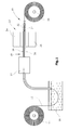
- Fig. 1 shows the individual steps of a first embodiment of a method for making a fiber reinforced continuous laminate 10.
- a plurality of substantially parallel glass or carbon fibers 12 are drawn from a roll 14 through a bath 16 of epoxy resin.
- Curable materials in which the fibers 12 are embedded can also be used.
- the composite of fibers 12 embedded in the epoxy resin is transported to a curing station 18. Thereafter, the cured laminate 20 is further transported to a channel forming station 22 comprising two grinding tools 24,26 for grinding the upper and lower major surfaces 28,30 of the cured laminate 20.
- a channel forming station 22 comprising two grinding tools 24,26 for grinding the upper and lower major surfaces 28,30 of the cured laminate 20.
- individual channels 32,34 are formed in the upper and lower major surfaces 28,30 of the cured laminate 20 in order to make the final prefabricated continuous fiber reinforced laminate 10 which thereafter is wound up as a coil 36. From this coil 36 several individual parts of the laminates (also referred to as panels) can be cut to be stacked on each other for producing a fiber reinforced laminate.
- channels 32,34 are formed in the major surfaces of the cured laminate 20 by grinding.
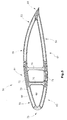
- the channels on each of the major surfaces are substantially parallel to each other while the sets of substantially parallel channels 32,34 are angled with respect to each other as well as with respect to the longitudinal direction of the continuous laminate 10.
- the channels 32,34 on the two major surfaces 28,30 of the continuous laminate 10 may have different dimensions.
- the channels 34 at the lower major surface 30 can be smaller in cross section than the channels 32 and the upper major surface 28 of the continuous laminate 10.
- Fig. 2 shows a cut piece of the continuous laminate 10 depicting the layers of fibers 12 as well as the sets of the channels 32 and 34 angled with respect to each other as well as with respect to the longitudinal direction of the continuous laminate 10. Moreover, one can see that the channels 32 and 34 are cut into to the upper and lower major surfaces 28,30, with also the fibers 12 arranged in these areas of the cut laminate.
- Channels 32,34 can also be formed by adding a peelply while manufacturing the continuous laminate and releasing it after curing.
- the fabric structure of the peelply can be chosen so as to give the desired surface condition to the continuous laminate.
- FIG. 3 An alternative process for making the continuous laminate 10 is shown in Fig. 3. As far as the elements shown in Fig. 3 are identical or similar to the elements shown in Figs. 1 and 2 the same reference numerals are used.
- Fig. 4 shows a cross sectional view of a wind energy turbine blade 50 comprising an upper and a lower shell 52,54 forming the shell of the blade 50.
- the shell of the blade 50 is comprised of upper and lower sandwiched structures 56,58 and 60,62 between which a spar 64 is arranged.
- the sandwiched structrues 56,58,60,62 each comprise rigid outer skins 66,68 with a spacer 70 therebetween (merely shown for laminate 56 in Fig. 3).
- the outer skins 66,68 may comprise a fiber reinforced resin while the spacer 70 may comprise a sandwiched structure, a foam or light weighted material like balsa wood.
- Those sandwiched structures are very well known in the manufacture of rotor blades.
- the spar 64 comprises an upper spar cap 72 and a lower spar cap 74 as well as two shear webs 76 therebetween.
- the shear webs 76 also are comprised of sandwiched structures as described earlier.
- the spar caps 72,74 as well as the front and rear ends 78,80 are made of a stack of portions of the laminates 10 manufactured and provided with surface channels as explained above in connection with Figs. 1 to 3.
- the blade 50 in Fig. 4 comprises laminated structures made of parts of the continuous laminate 10 manufactured in accordance with Figs. 1 to 3. These laminated structures, due to the channels 32 and 34 in the layers of the laminates, provide channels in which during the infusion process for manufacturing the blade 50 resin or the like curable material can be entered and completely and homogenously distributed between adjacent layers so that an ideal connection between adjacent layers of the laminates can be generated.
- the channels on at least one of the major surfaces of the continuous layer can be curved and/or intersect each other.
- roughening the continuous laminate provides for channel-like spaces between adjacent layers of the laminates.
Abstract
Description
- The present invention relates to a method for making a fiber reinforced endless or continuous laminate which can be used for manufacturing a spar cap or another part of a rotor blade of a wind energy turbine. Moreover, the present invention relates to the use of such a laminate for making structures such as a spar cap or another part of a rotor blade of a wind energy turbine.
- Continuous laminates, i.e. endless flat panels of fiber-reinforced resin or other curable material are basically known. These laminates are produced in a continuous process by pulling tows of fibers (e.g. of glass or carbon) through a bath of resin and by forming the panel thus obtained. Within the laminates the fibers are arranged side by side and are aligned substantially parallel to each other. These continuous laminates can have a thickness between under 1 mm and up to several mm. The width of the laminate can be realised in substantially every dimension. The matrix material (e.g. resin) is cured in an endless process and the sheet-like laminate is wound up into coils with a length of a couple of hundreds of meters. These laminates are suitable to stack up parts or layers thereof for e.g. a spar cap of a blade of a wind energy turbine. As the fibers are substantially perfectly aligned and maintained in this alignment within the prefabricated laminates, the risk of fiber misalignment (to which especially the carbon fibers are very sensitive) upon arranging the individual layers of the laminate in the mould for manufacturing the blade is reduced.
- Continuous fiber reinforced laminates as described above are sold e.g. by the Finnish company EXEL.
- Using the continuous prefabricated fiber reinforced laminates for manufacturing a spar cap or another part of a wind energy turbine rotor blade involves an arrangement in which several layers of cut pieces of the laminate have to be arranged on top of each other in order to make a structure. These structures are arranged within specific areas and regions of a rotor blade mould in which also other sandwiched structures are placed. The spar cap and sandwich structure of the rotor blade provides for a rigid and shear-resistant overall structure which is light in weight and very stable. In order to manufacture the blade, an infusion process is used during which curable material (e.g. resin) is flowing into the mould in order to penetrate between the layers of the laminate as well as the structural members of the rotor blade. During the infusion process the laminate layers are pressed together due to a vacuum applied to the mould. Such infusion processes are also used for manufacturing other elements made from laminates. During these processes it might happen that the curable material flowing into the mould does not penetrate all the way through between the layers of the laminates. This results in an insufficient mechanical connection of adjacent layers of the laminates, and, accordingly, in a less rigid and stable structural element of the rotor blade or another part made from the fiber reinforced laminates by the infusion process.
- The above-mentioned problem is solved by a method for making a continuous laminate, in particular suitable as a spar cap or another part of a wind energy turbine rotor blade, the method comprising the steps of
- providing a plurality of parallel fibers,
- embedding the fibers in a curable matrix material,
- curing the matrix material so as to obtain a fiber reinforced laminate having upper and lower major surfaces, and
- forming channels into at least one of the upper and lower major surfaces of the laminate wherein the channels on the upper and/or lower major surfaces are angled with respect to the direction of the fibers.
- Accordingly, by way of the invention at least one surface of the continuous fiber reinforced continuous laminate is prepared so as to comprise channels for the curable material (e.g. resin) to move in between the layers of the continuous laminate arranged in a stack during an infusion process. The goal of the invention is the provision of a well-adjusted room between adjacent layers of a stack of continuous laminates even under high pressure. This is achieved by forming channels in at least one of the surfaces of the continuous laminates after primer fabrication and curing of the continuous laminate or simultaneously therewith.
- In one aspect of the invention the channels are formed by grinding at least one of the major surfaces of the fiber reinforced continuous laminate by means of a grinding tool. The grinding tool is moved crosswise to the fibers of the fiber reinforced continuous laminate and to the machine direction of the fiber reinforced continuous laminate production process. This creates crosswise channels by partly grinding away material on at least one of the upper and lower major surfaces of the continuous laminate. Thereby, the fibers are cut up to the depth of the grinding cuts. The cut fibers should be subtracted from the load carrying cross sectional area of the continuous laminate. By adjusting the speed of the moving continuous laminate and the grinding tool, the angle of the channels can be adjusted relative to the main access (longitudinal direction) of the continuous laminate. Most preferably forming channels is to be applied to both major surfaces of the continuous laminate. Making the angles of the channels of the upper and lower major surfaces different from each other or just switching them from plus to minus, guaranties intersections of the channels so that the channels at the upper and lower major surfaces of the continuous laminate cannot match and close each other during stacking several layers of the continuous laminate. The roughness of the grinder or other channel forming tool should be adjusted to meet the requirements of the curable material (e.g. resin) to be moved between the layers and to minimize the flow drag of the entering curable material during the infusing process.
- According to another aspect of the present invention the formation of the channels in the upper and/or lower major surface of the continuous laminate is performed while the matrix material of the continuous laminate cures. In this process, the channels preferably are not formed within the thickness areas of the continuous laminate within which the fibers are arranged. Accordingly, the continuous laminate comprises upper and/or lower thickness portions within which the channels are provided, and a middle portion arranged therebetween within which the fibers are arranged.
- Further embodiments and aspects of the invention are the subject matter of the claims.
- The present invention will be described in more detail hereinbelow referring to the drawings in which
- Fig. 1
- shows schematically the individual process steps according to a first embodiment of a method for making a fiber reinforced continuous laminate according to the invention,
- Fig. 2
- shows a perspective view of a cut portion of the laminate made in accordance with the process schematically shown in Fig. 1,
- Fig. 3
- shows schematically the individual process steps according to a first embodiment of a method for making a fiber reinforced continuous laminate according to a second embodiment of the present invention,
- Fig. 4
- shows a cross sectional view of a rotor blade comprising a spar and other parts formed by a stack of layers of the continuous laminate laminated to each other.
- Fig. 1 shows the individual steps of a first embodiment of a method for making a fiber reinforced
continuous laminate 10. A plurality of substantially parallel glass orcarbon fibers 12 are drawn from aroll 14 through abath 16 of epoxy resin. However, other Curable materials in which thefibers 12 are embedded, can also be used. - The composite of
fibers 12 embedded in the epoxy resin is transported to acuring station 18. Thereafter, the curedlaminate 20 is further transported to achannel forming station 22 comprising twogrinding tools major surfaces laminate 20. In thechannel forming station 22, by means of the upper andlower grinding tools individual channels major surfaces laminate 20 in order to make the final prefabricated continuous fiber reinforcedlaminate 10 which thereafter is wound up as acoil 36. From thiscoil 36 several individual parts of the laminates (also referred to as panels) can be cut to be stacked on each other for producing a fiber reinforced laminate. - Within the
channel forming station 22,channels laminate 20 by grinding. The channels on each of the major surfaces are substantially parallel to each other while the sets of substantiallyparallel channels continuous laminate 10. Also thechannels major surfaces continuous laminate 10 may have different dimensions. For example thechannels 34 at the lowermajor surface 30 can be smaller in cross section than thechannels 32 and the uppermajor surface 28 of thecontinuous laminate 10. - Fig. 2 shows a cut piece of the
continuous laminate 10 depicting the layers offibers 12 as well as the sets of thechannels continuous laminate 10. Moreover, one can see that thechannels major surfaces fibers 12 arranged in these areas of the cut laminate. -
Channels - An alternative process for making the
continuous laminate 10 is shown in Fig. 3. As far as the elements shown in Fig. 3 are identical or similar to the elements shown in Figs. 1 and 2 the same reference numerals are used. -
Several fibers 12 of glass or carbon are drawn from aroll 14 and set through abath 16 of curable material (e.g. epoxy resin). Thereafter, the composite of resin with thefibers 12 embedded therein, is transported to a curing andchannel forming station channels major surfaces lower chain 38,40 having individual dies 42,44 are arranged above and below the composite 10 so as to form thechannels lower portions fibers 12 are embedded. The fabricatedcontinuous laminate 10 is again wound up as acoil 36. - Fig. 4 shows a cross sectional view of a wind
energy turbine blade 50 comprising an upper and alower shell blade 50. The shell of theblade 50 is comprised of upper and lower sandwichedstructures spar 64 is arranged. The sandwiched structrues 56,58,60,62 each comprise rigidouter skins spacer 70 therebetween (merely shown forlaminate 56 in Fig. 3). Theouter skins spacer 70 may comprise a sandwiched structure, a foam or light weighted material like balsa wood. Those sandwiched structures are very well known in the manufacture of rotor blades. - The
spar 64 comprises anupper spar cap 72 and alower spar cap 74 as well as twoshear webs 76 therebetween. Theshear webs 76 also are comprised of sandwiched structures as described earlier. The spar caps 72,74 as well as the front andrear ends laminates 10 manufactured and provided with surface channels as explained above in connection with Figs. 1 to 3. - The overall construction of the
blade 50 as shown in Fig. 4 with its individual sandwiched and laminated portions is basically known. However, according to the invention theblade 50 in Fig. 4 comprises laminated structures made of parts of thecontinuous laminate 10 manufactured in accordance with Figs. 1 to 3. These laminated structures, due to thechannels blade 50 resin or the like curable material can be entered and completely and homogenously distributed between adjacent layers so that an ideal connection between adjacent layers of the laminates can be generated. - Although the invention has been described and illustrated with reference to specific illustrative embodiments thereof, it is not intended that the invention be limited to those illustrative embodiments. For example, the channels on at least one of the major surfaces of the continuous layer can be curved and/or intersect each other. Also roughening the continuous laminate provides for channel-like spaces between adjacent layers of the laminates. Those skilled in the art will recognise that variations and modifications can be made without departing from the true scope of the invention as defined by the claims that follow. It is therefore intended to include within the invention all such variations and modifications as fall within the scope of the appended claims and equivalents thereof.
Claims (11)
- A method for making a continuous laminate, in particular suitable as a spar cap or another part of a wind energy turbine rotor blade, the method comprising the steps of- providing a plurality of parallel fibers (12),- embedding the fibers (12) in a curable matrix material (16),- curing the matrix material (16) so as to obtain a fiber reinforced laminate (20) having upper and lower major surfaces (28,30), and- forming channels (32,34) into at least one of the major upper and lower major surfaces (28,30) of the laminate (20) wherein the channels (32,34) on the upper and/or lower major surfaces (28,30) are angled with respect to the direction of the fibers (12).
- The method according to claim 1 wherein channels (32, 34) are formed in both of the upper and lower major surfaces (28,30) of the continuous laminate (10) wherein the channels (32,34) on the upper major surface (28) are angled with respect to the channels (34) on the lower major surface (30).
- The method according to claim 1 or 2 wherein the channels (32,34) are cut into the upper and/or lower major surface (28,30) of the continuous laminate (10) after curing of its matrix material.
- The method according to claim 3 wherein cutting is performed using at least one grinding tool (24,26).
- The method according to claim 1 or 2 wherein the channels (32,34) are formed into the upper and/or lower major surface (28,30) while the matrix material (16) cures.
- The method according to any one of claims 1 to 5 wherein the fibers (12) are selected from at least one of glass or carbon fibers.
- The method according to any one of claims 1 to 6 wherein the matrix material (16) is a resin and, in particular, an epoxy resin.
- The method according to any one of claims 1 to 7 wherein the channels (32,34) on one major surface (28,30) are substantially parallel to each other, respectively.
- The method according to any one of claims 1 to 8 wherein the channels (32,34) extend up to the edge of the laminate (20).
- Use of laminates (10) manufactured according to any of the proceeding claims in an infusion process for making structures from the laminate (10) by arranging layers of the laminate (10) on top of each other within a mould and infusing a curable material between the layers of the laminate (10) arranged within the mould.
- Use according to claim 10 for making a rotor blade (50) of a wind energy turbine.
Priority Applications (4)
| Application Number | Priority Date | Filing Date | Title |
|---|---|---|---|
| EP05107575.2A EP1754589B1 (en) | 2005-08-17 | 2005-08-17 | Use of continuous laminates, in particular suitable as a spar cap or another part of a wind energy turbine rotor blade |
| DK05107575.2T DK1754589T3 (en) | 2005-08-17 | 2005-08-17 | Use of the continuous laminate, in particular suitable as a beam cover or other part of a vindmøllerotorvinge |
| US11/462,453 US8226866B2 (en) | 2005-08-17 | 2006-08-04 | Method for making a continuous laminate, in particular suitable as a spar cap or another part of a wind energy turbine rotor blade |
| CN2006101262346A CN1915649B (en) | 2005-08-17 | 2006-08-17 | Method for making a continuous laminate, in particular suitable as a spar cap or another part of a wind energy turbine rotor blade |
Applications Claiming Priority (1)
| Application Number | Priority Date | Filing Date | Title |
|---|---|---|---|
| EP05107575.2A EP1754589B1 (en) | 2005-08-17 | 2005-08-17 | Use of continuous laminates, in particular suitable as a spar cap or another part of a wind energy turbine rotor blade |
Publications (2)
| Publication Number | Publication Date |
|---|---|
| EP1754589A1 true EP1754589A1 (en) | 2007-02-21 |
| EP1754589B1 EP1754589B1 (en) | 2015-10-14 |
Family
ID=35570181
Family Applications (1)
| Application Number | Title | Priority Date | Filing Date |
|---|---|---|---|
| EP05107575.2A Active EP1754589B1 (en) | 2005-08-17 | 2005-08-17 | Use of continuous laminates, in particular suitable as a spar cap or another part of a wind energy turbine rotor blade |
Country Status (4)
| Country | Link |
|---|---|
| US (1) | US8226866B2 (en) |
| EP (1) | EP1754589B1 (en) |
| CN (1) | CN1915649B (en) |
| DK (1) | DK1754589T3 (en) |
Cited By (19)
| Publication number | Priority date | Publication date | Assignee | Title |
|---|---|---|---|---|
| WO2008092451A2 (en) * | 2007-01-29 | 2008-08-07 | Danmarks Tekniske Universitet | Wind turbine blade |
| WO2009133143A1 (en) * | 2008-04-30 | 2009-11-05 | Vestas Wind Systems A/S | A consolidated composite pre-from |
| WO2010034755A2 (en) * | 2008-09-23 | 2010-04-01 | Groep Stevens International | Use of a composite article as spar component |
| EP2405130A1 (en) * | 2010-07-08 | 2012-01-11 | Lm Glasfiber A/S | Notch-reduced composite joint |
| WO2013007351A1 (en) * | 2011-07-11 | 2013-01-17 | Repower Systems Se | Method for producing a rotor blade for a wind turbine, sandwich preform and rotor blade for a wind turbine |
| US8454318B2 (en) | 2006-12-15 | 2013-06-04 | Bladena Aps | Reinforced aerodynamic profile |
| US8485786B2 (en) | 2007-01-16 | 2013-07-16 | Bladena Aps | Reinforced blade for wind turbine |
| EP2341239A3 (en) * | 2009-12-30 | 2014-01-01 | General Electric Company | Spar for a wind turbine rotor blade |
| US8632312B2 (en) | 2007-01-25 | 2014-01-21 | Bladena Aps | Reinforced blade for wind turbine |
| WO2014079565A3 (en) * | 2012-11-20 | 2014-07-17 | Hexcel Composites Limited | Moulding material |
| US8807953B2 (en) | 2008-06-24 | 2014-08-19 | Bladena Aps | Reinforced wind turbine blade |
| DE102014221965A1 (en) * | 2014-10-28 | 2016-04-28 | Senvion Gmbh | Rotor blade for a wind turbine and method for manufacturing a rotor blade |
| US9416768B2 (en) | 2009-12-02 | 2016-08-16 | Bladena Aps | Reinforced airfoil shaped body |
| EP2791500B1 (en) | 2011-12-16 | 2019-03-06 | Vestas Wind Systems A/S | Wind turbine blade and production method |
| EP3501810A1 (en) * | 2017-12-22 | 2019-06-26 | Siemens Gamesa Renewable Energy A/S | Pultruded fibrous composite strips having corrugated profiles for wind turbine blade spar caps |
| EP3511154A1 (en) * | 2018-01-15 | 2019-07-17 | Siemens Gamesa Renewable Energy A/S | Method for fabrication of a profile for a spar cap for a wind turbine blade, spar cap and wind turbine blade |
| EP3564017A1 (en) * | 2018-05-03 | 2019-11-06 | Siemens Gamesa Renewable Energy A/S | Pultrusion tool, apparatus and method |
| CN113352649A (en) * | 2021-06-17 | 2021-09-07 | 上海瓴荣材料科技有限公司 | Forming device and preparation method of fiber reinforced nylon wind power crossbeam |
| US11858225B2 (en) | 2017-05-09 | 2024-01-02 | Vestas Wind Systems A/S | Pultruded strips |
Families Citing this family (32)
| Publication number | Priority date | Publication date | Assignee | Title |
|---|---|---|---|---|
| DK1990178T3 (en) | 2007-05-07 | 2010-10-04 | Siemens Ag | Method of manufacturing a rotor blade for a wind turbine |
| CN102066747A (en) * | 2008-06-23 | 2011-05-18 | 丹麦技术大学 | A wind turbine blade with angled girders |
| CA2741479A1 (en) * | 2008-10-22 | 2010-04-29 | Vec Industries, L.L.C. | Wind turbine blade and method for manufacturing thereof |
| EP2358998B1 (en) | 2008-12-05 | 2017-09-20 | Vestas Wind Systems A/S | Efficient wind turbine blades, wind turbine blade structures, and associated systems and methods of manufacture, assembly and use |
| US7841835B2 (en) * | 2009-02-20 | 2010-11-30 | General Electric Company | Spar cap for wind turbine blades |
| US8753091B1 (en) | 2009-05-20 | 2014-06-17 | A&P Technology, Inc. | Composite wind turbine blade and method for manufacturing same |
| CN102022254B (en) * | 2009-09-23 | 2014-12-17 | 固瑞特模具(太仓)有限公司 | Wind turbine blade and manufacturing method thereof |
| US8702397B2 (en) * | 2009-12-01 | 2014-04-22 | General Electric Company | Systems and methods of assembling a rotor blade for use in a wind turbine |
| JP2011137386A (en) * | 2009-12-25 | 2011-07-14 | Mitsubishi Heavy Ind Ltd | Wind turbine rotor blade and method of manufacturing wind turbine rotor blade |
| US8142164B2 (en) * | 2009-12-31 | 2012-03-27 | General Electric Company | Rotor blade for use with a wind turbine and method for assembling rotor blade |
| ES2431602T3 (en) * | 2010-05-21 | 2013-11-27 | Siemens Aktiengesellschaft | Shovel of a wind turbine |
| US9500179B2 (en) | 2010-05-24 | 2016-11-22 | Vestas Wind Systems A/S | Segmented wind turbine blades with truss connection regions, and associated systems and methods |
| US9579861B2 (en) * | 2011-01-05 | 2017-02-28 | Vestas Wind Systems A/S | Laminate pre-form for a wind turbine blade |
| FR2972503B1 (en) | 2011-03-11 | 2013-04-12 | Epsilon Composite | MECHANICAL REINFORCEMENT FOR A COMPOSITE MATERIAL PART, IN PARTICULAR FOR A LARGE-SIZED WINDBREAD BLADE |
| US8622707B2 (en) * | 2011-12-19 | 2014-01-07 | General Electric Company | Root attachment for a rotor blade assembly |
| US8449259B1 (en) | 2012-05-15 | 2013-05-28 | Modular Wind Energy, Inc. | Lightning protection for wind turbine blades, and associated systems and methods |
| CA2878032C (en) * | 2012-07-20 | 2019-06-25 | Ahlstrom Corporation | A unidirectional reinforcement and a method of producing a unidirectional reinforcement |
| US9470205B2 (en) | 2013-03-13 | 2016-10-18 | Vestas Wind Systems A/S | Wind turbine blades with layered, multi-component spars, and associated systems and methods |
| GB2519566A (en) | 2013-10-25 | 2015-04-29 | Vestas Wind Sys As | Wind turbine blades |
| GB2520007A (en) | 2013-11-05 | 2015-05-13 | Vestas Wind Sys As | Improvements relating to wind turbine rotor blades |
| US10533535B2 (en) * | 2014-03-19 | 2020-01-14 | Korecarbon Llc | Turbine blade |
| DE102015206917B4 (en) * | 2015-04-16 | 2022-03-17 | Bayerische Motoren Werke Aktiengesellschaft | Pultrusion of endless profiles with a discontinuous cross-section |
| DE102015007801A1 (en) | 2015-06-19 | 2016-12-22 | Senvion Gmbh | Method for producing a component of a rotor blade of a wind energy plant |
| US10077758B2 (en) * | 2015-06-30 | 2018-09-18 | General Electric Company | Corrugated pre-cured laminate plates for use within wind turbine rotor blades |
| DE102015225467B4 (en) * | 2015-12-16 | 2019-12-19 | Airbus Defence and Space GmbH | Coated composite component and method for producing a coated composite component |
| WO2017204945A1 (en) | 2016-05-26 | 2017-11-30 | Ocv Intellectual Capital, Llc | System for making fibre-reinforcing materials for structural components |
| EP3354450A1 (en) | 2017-01-27 | 2018-08-01 | Nordex Energy GmbH | Pultruded profile for a structural component of a wind power plant |
| DE102017112721A1 (en) * | 2017-06-09 | 2018-12-13 | Wobben Properties Gmbh | Method for producing a wind turbine rotor blade |
| US11498748B2 (en) | 2017-11-29 | 2022-11-15 | Owens Corning Intellectual Capital, Llc | Pallet with rolls of reinforcement material |
| CN112236290A (en) | 2018-06-07 | 2021-01-15 | Ocv智识资本有限责任公司 | System and method for forming structural components |
| WO2020055396A1 (en) * | 2018-09-11 | 2020-03-19 | Tpi Composites, Inc. | Positioning profiles for pultrusions in wind blade spar caps |
| CN109676971A (en) * | 2019-02-15 | 2019-04-26 | 浙江新纳复合材料有限公司 | A kind of production technology and its production line of profiled filament muscle material |
Citations (6)
| Publication number | Priority date | Publication date | Assignee | Title |
|---|---|---|---|---|
| FR2424470A1 (en) * | 1978-04-26 | 1979-11-23 | Amf Inc | Stiff structures moulded with tubular and cellular cores - for skis, wings etc. of high specific stiffness |
| NL8104019A (en) * | 1981-08-28 | 1983-03-16 | Jan Bos | Fibre-reinforced plastic object has parallel reinforcing rods - with passages between for full penetration by liquid plastic on moulding |
| JPH036093A (en) * | 1989-06-02 | 1991-01-11 | Hitachi Chem Co Ltd | Prepreg sheet for multilayer printed wiring board |
| US5104718A (en) * | 1989-02-28 | 1992-04-14 | Mitsubishi Rayon Co., Ltd. | Prepreg and process for producing the same |
| US5421931A (en) * | 1991-07-18 | 1995-06-06 | Carmien; Joseph A. | Process for manufacturing reinforced rod assemblies, including tool handles |
| DE10014376A1 (en) * | 2000-01-18 | 2001-07-19 | Thomas Gmbh & Co Technik Innovation Kg | Pultrusion process for producing long plastic composite strips for seating springs includes an additional continuous forming member passing through the die with the preform |
Family Cites Families (4)
| Publication number | Priority date | Publication date | Assignee | Title |
|---|---|---|---|---|
| DE3920946A1 (en) * | 1989-06-27 | 1991-01-03 | Held Kurt | DEVICE FOR THE CONTINUOUS PRODUCTION OF LAMINATES |
| GB2375501B (en) * | 2001-05-03 | 2003-07-09 | Morgan Crucible Co | Extrusion of graphitic bodies |
| US6726809B2 (en) * | 2001-09-26 | 2004-04-27 | Albany International Corp. | Industrial process fabric |
| US7247003B2 (en) * | 2004-12-02 | 2007-07-24 | Siemens Power Generation, Inc. | Stacked lamellate assembly |
-
2005
- 2005-08-17 DK DK05107575.2T patent/DK1754589T3/en active
- 2005-08-17 EP EP05107575.2A patent/EP1754589B1/en active Active
-
2006
- 2006-08-04 US US11/462,453 patent/US8226866B2/en active Active
- 2006-08-17 CN CN2006101262346A patent/CN1915649B/en active Active
Patent Citations (6)
| Publication number | Priority date | Publication date | Assignee | Title |
|---|---|---|---|---|
| FR2424470A1 (en) * | 1978-04-26 | 1979-11-23 | Amf Inc | Stiff structures moulded with tubular and cellular cores - for skis, wings etc. of high specific stiffness |
| NL8104019A (en) * | 1981-08-28 | 1983-03-16 | Jan Bos | Fibre-reinforced plastic object has parallel reinforcing rods - with passages between for full penetration by liquid plastic on moulding |
| US5104718A (en) * | 1989-02-28 | 1992-04-14 | Mitsubishi Rayon Co., Ltd. | Prepreg and process for producing the same |
| JPH036093A (en) * | 1989-06-02 | 1991-01-11 | Hitachi Chem Co Ltd | Prepreg sheet for multilayer printed wiring board |
| US5421931A (en) * | 1991-07-18 | 1995-06-06 | Carmien; Joseph A. | Process for manufacturing reinforced rod assemblies, including tool handles |
| DE10014376A1 (en) * | 2000-01-18 | 2001-07-19 | Thomas Gmbh & Co Technik Innovation Kg | Pultrusion process for producing long plastic composite strips for seating springs includes an additional continuous forming member passing through the die with the preform |
Non-Patent Citations (1)
| Title |
|---|
| PATENT ABSTRACTS OF JAPAN vol. 015, no. 114 (E - 1047) 19 March 1991 (1991-03-19) * |
Cited By (33)
| Publication number | Priority date | Publication date | Assignee | Title |
|---|---|---|---|---|
| US8454318B2 (en) | 2006-12-15 | 2013-06-04 | Bladena Aps | Reinforced aerodynamic profile |
| US8485786B2 (en) | 2007-01-16 | 2013-07-16 | Bladena Aps | Reinforced blade for wind turbine |
| US8632312B2 (en) | 2007-01-25 | 2014-01-21 | Bladena Aps | Reinforced blade for wind turbine |
| WO2008092451A2 (en) * | 2007-01-29 | 2008-08-07 | Danmarks Tekniske Universitet | Wind turbine blade |
| WO2008092451A3 (en) * | 2007-01-29 | 2008-12-11 | Univ Danmarks Tekniske | Wind turbine blade |
| CN102123852B (en) * | 2008-04-30 | 2014-03-19 | 维斯塔斯风力系统有限公司 | A consolidated composite pre-from |
| WO2009133143A1 (en) * | 2008-04-30 | 2009-11-05 | Vestas Wind Systems A/S | A consolidated composite pre-from |
| CN102123852A (en) * | 2008-04-30 | 2011-07-13 | 维斯塔斯风力系统有限公司 | A consolidated composite pre-from |
| US8986487B2 (en) | 2008-04-30 | 2015-03-24 | Vestas Wind Systems A/S | Consolidated composite pre-form |
| US9784240B2 (en) | 2008-06-24 | 2017-10-10 | Bladena Solutions Aps | Reinforced wind turbine blade |
| US8807953B2 (en) | 2008-06-24 | 2014-08-19 | Bladena Aps | Reinforced wind turbine blade |
| WO2010034755A2 (en) * | 2008-09-23 | 2010-04-01 | Groep Stevens International | Use of a composite article as spar component |
| WO2010034755A3 (en) * | 2008-09-23 | 2010-10-28 | Groep Stevens International | Use of a composite article as spar component |
| US9416768B2 (en) | 2009-12-02 | 2016-08-16 | Bladena Aps | Reinforced airfoil shaped body |
| EP2341239A3 (en) * | 2009-12-30 | 2014-01-01 | General Electric Company | Spar for a wind turbine rotor blade |
| EP2405130A1 (en) * | 2010-07-08 | 2012-01-11 | Lm Glasfiber A/S | Notch-reduced composite joint |
| WO2012004383A3 (en) * | 2010-07-08 | 2012-11-29 | Lm Glasfiber A/S | Notch-reduced composite joint |
| US9366223B2 (en) | 2010-07-08 | 2016-06-14 | Lm Glasfiber A/S | Notch-reduced composite joint |
| WO2013007351A1 (en) * | 2011-07-11 | 2013-01-17 | Repower Systems Se | Method for producing a rotor blade for a wind turbine, sandwich preform and rotor blade for a wind turbine |
| DE102011078951C5 (en) * | 2011-07-11 | 2017-09-07 | Senvion Gmbh | Method for producing a rotor blade for a wind energy plant |
| EP2791500B1 (en) | 2011-12-16 | 2019-03-06 | Vestas Wind Systems A/S | Wind turbine blade and production method |
| US11629690B2 (en) | 2011-12-16 | 2023-04-18 | Vestas Wind Systems A/S | Wind turbine blades |
| US11371482B2 (en) | 2011-12-16 | 2022-06-28 | Vestas Wind Systems A/S | Wind turbine blades |
| CN104812812A (en) * | 2012-11-20 | 2015-07-29 | 赫克塞尔合成有限公司 | Moulding material |
| WO2014079565A3 (en) * | 2012-11-20 | 2014-07-17 | Hexcel Composites Limited | Moulding material |
| DE102014221965A1 (en) * | 2014-10-28 | 2016-04-28 | Senvion Gmbh | Rotor blade for a wind turbine and method for manufacturing a rotor blade |
| US11858225B2 (en) | 2017-05-09 | 2024-01-02 | Vestas Wind Systems A/S | Pultruded strips |
| US11231008B2 (en) | 2017-12-22 | 2022-01-25 | Siemens Gamesa Renewable Energy A/S | Pultruded fibrous composite strips having corrugated profiles for wind turbine blade spar caps |
| EP3501810A1 (en) * | 2017-12-22 | 2019-06-26 | Siemens Gamesa Renewable Energy A/S | Pultruded fibrous composite strips having corrugated profiles for wind turbine blade spar caps |
| EP3511154A1 (en) * | 2018-01-15 | 2019-07-17 | Siemens Gamesa Renewable Energy A/S | Method for fabrication of a profile for a spar cap for a wind turbine blade, spar cap and wind turbine blade |
| US11187204B2 (en) | 2018-01-15 | 2021-11-30 | Siemens Gamesa Renewable Energy A/S | Method for fabrication of a profile for a spar cap for a wind turbine blade, spar cap and wind turbine blade |
| EP3564017A1 (en) * | 2018-05-03 | 2019-11-06 | Siemens Gamesa Renewable Energy A/S | Pultrusion tool, apparatus and method |
| CN113352649A (en) * | 2021-06-17 | 2021-09-07 | 上海瓴荣材料科技有限公司 | Forming device and preparation method of fiber reinforced nylon wind power crossbeam |
Also Published As
| Publication number | Publication date |
|---|---|
| US20070040294A1 (en) | 2007-02-22 |
| US8226866B2 (en) | 2012-07-24 |
| CN1915649A (en) | 2007-02-21 |
| DK1754589T3 (en) | 2016-01-04 |
| EP1754589B1 (en) | 2015-10-14 |
| CN1915649B (en) | 2012-08-22 |
Similar Documents
| Publication | Publication Date | Title |
|---|---|---|
| EP1754589B1 (en) | Use of continuous laminates, in particular suitable as a spar cap or another part of a wind energy turbine rotor blade | |
| EP2922690B1 (en) | Wind turbine blades and method of manufacturing the same | |
| EP2295235B1 (en) | Fiber reinforced plastic-structure and a method to produce the fiber reinforced plastic-structure | |
| US8114329B2 (en) | Wing and blade structure using pultruded composites | |
| EP1786617B1 (en) | A method of cutting off laminate layers, eg a glass-fibre or carbon-fibre laminate layer in the blade of a wind turbine | |
| EP3068614B1 (en) | Wind turbine blades | |
| EP2441571B1 (en) | Proces for manufacturing a composite component | |
| CA2713031C (en) | Method to manufacture at least a component of a blade of a wind-turbine | |
| EP3894190B1 (en) | Method of forming a wind turbine blade shear web flange section and a wind turbine blade shear web. | |
| US9403340B2 (en) | Method of manufacturing a composite load-bearing structure | |
| EP3894189B1 (en) | Wind turbine blade shear web, method of manufacture and wind turbine blade | |
| CN113954388B (en) | Prefabricated limiting part, spar cap, fan blade, manufacturing method and prefabricated plate fixing method | |
| US20220364542A1 (en) | Method and system of manufacturing a wind turbine blade | |
| WO2023117013A1 (en) | Improvements relating to wind turbine blades | |
| DK2580046T3 (en) | METHOD AND DEVICE FOR MAKING COMPOSITION PROFILE WITH A NON-CIRCULAR SECTION |
Legal Events
| Date | Code | Title | Description |
|---|---|---|---|
| PUAI | Public reference made under article 153(3) epc to a published international application that has entered the european phase |
Free format text: ORIGINAL CODE: 0009012 |
|
| AK | Designated contracting states |
Kind code of ref document: A1 Designated state(s): AT BE BG CH CY CZ DE DK EE ES FI FR GB GR HU IE IS IT LI LT LU LV MC NL PL PT RO SE SI SK TR |
|
| AX | Request for extension of the european patent |
Extension state: AL BA HR MK YU |
|
| 17P | Request for examination filed |
Effective date: 20070425 |
|
| 17Q | First examination report despatched |
Effective date: 20070524 |
|
| AKX | Designation fees paid |
Designated state(s): AT BE BG CH CY CZ DE DK EE ES FI FR GB GR HU IE IS IT LI LT LU LV MC NL PL PT RO SE SI SK TR |
|
| GRAP | Despatch of communication of intention to grant a patent |
Free format text: ORIGINAL CODE: EPIDOSNIGR1 |
|
| INTG | Intention to grant announced |
Effective date: 20150605 |
|
| GRAS | Grant fee paid |
Free format text: ORIGINAL CODE: EPIDOSNIGR3 |
|
| GRAA | (expected) grant |
Free format text: ORIGINAL CODE: 0009210 |
|
| AK | Designated contracting states |
Kind code of ref document: B1 Designated state(s): AT BE BG CH CY CZ DE DK EE ES FI FR GB GR HU IE IS IT LI LT LU LV MC NL PL PT RO SE SI SK TR |
|
| REG | Reference to a national code |
Ref country code: GB Ref legal event code: FG4D |
|
| REG | Reference to a national code |
Ref country code: AT Ref legal event code: REF Ref document number: 754792 Country of ref document: AT Kind code of ref document: T Effective date: 20151015 Ref country code: CH Ref legal event code: EP |
|
| REG | Reference to a national code |
Ref country code: IE Ref legal event code: FG4D |
|
| REG | Reference to a national code |
Ref country code: DE Ref legal event code: R096 Ref document number: 602005047674 Country of ref document: DE |
|
| REG | Reference to a national code |
Ref country code: DK Ref legal event code: T3 Effective date: 20151223 |
|
| REG | Reference to a national code |
Ref country code: NL Ref legal event code: MP Effective date: 20151014 |
|
| REG | Reference to a national code |
Ref country code: LT Ref legal event code: MG4D |
|
| REG | Reference to a national code |
Ref country code: AT Ref legal event code: MK05 Ref document number: 754792 Country of ref document: AT Kind code of ref document: T Effective date: 20151014 |
|
| PG25 | Lapsed in a contracting state [announced via postgrant information from national office to epo] |
Ref country code: ES Free format text: LAPSE BECAUSE OF FAILURE TO SUBMIT A TRANSLATION OF THE DESCRIPTION OR TO PAY THE FEE WITHIN THE PRESCRIBED TIME-LIMIT Effective date: 20151014 Ref country code: IS Free format text: LAPSE BECAUSE OF FAILURE TO SUBMIT A TRANSLATION OF THE DESCRIPTION OR TO PAY THE FEE WITHIN THE PRESCRIBED TIME-LIMIT Effective date: 20160214 Ref country code: IT Free format text: LAPSE BECAUSE OF FAILURE TO SUBMIT A TRANSLATION OF THE DESCRIPTION OR TO PAY THE FEE WITHIN THE PRESCRIBED TIME-LIMIT Effective date: 20151014 Ref country code: NL Free format text: LAPSE BECAUSE OF FAILURE TO SUBMIT A TRANSLATION OF THE DESCRIPTION OR TO PAY THE FEE WITHIN THE PRESCRIBED TIME-LIMIT Effective date: 20151014 Ref country code: LT Free format text: LAPSE BECAUSE OF FAILURE TO SUBMIT A TRANSLATION OF THE DESCRIPTION OR TO PAY THE FEE WITHIN THE PRESCRIBED TIME-LIMIT Effective date: 20151014 |
|
| PG25 | Lapsed in a contracting state [announced via postgrant information from national office to epo] |
Ref country code: LV Free format text: LAPSE BECAUSE OF FAILURE TO SUBMIT A TRANSLATION OF THE DESCRIPTION OR TO PAY THE FEE WITHIN THE PRESCRIBED TIME-LIMIT Effective date: 20151014 Ref country code: AT Free format text: LAPSE BECAUSE OF FAILURE TO SUBMIT A TRANSLATION OF THE DESCRIPTION OR TO PAY THE FEE WITHIN THE PRESCRIBED TIME-LIMIT Effective date: 20151014 Ref country code: PT Free format text: LAPSE BECAUSE OF FAILURE TO SUBMIT A TRANSLATION OF THE DESCRIPTION OR TO PAY THE FEE WITHIN THE PRESCRIBED TIME-LIMIT Effective date: 20160215 Ref country code: SE Free format text: LAPSE BECAUSE OF FAILURE TO SUBMIT A TRANSLATION OF THE DESCRIPTION OR TO PAY THE FEE WITHIN THE PRESCRIBED TIME-LIMIT Effective date: 20151014 Ref country code: GR Free format text: LAPSE BECAUSE OF FAILURE TO SUBMIT A TRANSLATION OF THE DESCRIPTION OR TO PAY THE FEE WITHIN THE PRESCRIBED TIME-LIMIT Effective date: 20160115 Ref country code: PL Free format text: LAPSE BECAUSE OF FAILURE TO SUBMIT A TRANSLATION OF THE DESCRIPTION OR TO PAY THE FEE WITHIN THE PRESCRIBED TIME-LIMIT Effective date: 20151014 Ref country code: FI Free format text: LAPSE BECAUSE OF FAILURE TO SUBMIT A TRANSLATION OF THE DESCRIPTION OR TO PAY THE FEE WITHIN THE PRESCRIBED TIME-LIMIT Effective date: 20151014 |
|
| REG | Reference to a national code |
Ref country code: DE Ref legal event code: R097 Ref document number: 602005047674 Country of ref document: DE |
|
| PG25 | Lapsed in a contracting state [announced via postgrant information from national office to epo] |
Ref country code: CZ Free format text: LAPSE BECAUSE OF FAILURE TO SUBMIT A TRANSLATION OF THE DESCRIPTION OR TO PAY THE FEE WITHIN THE PRESCRIBED TIME-LIMIT Effective date: 20151014 |
|
| PLBE | No opposition filed within time limit |
Free format text: ORIGINAL CODE: 0009261 |
|
| STAA | Information on the status of an ep patent application or granted ep patent |
Free format text: STATUS: NO OPPOSITION FILED WITHIN TIME LIMIT |
|
| PG25 | Lapsed in a contracting state [announced via postgrant information from national office to epo] |
Ref country code: SK Free format text: LAPSE BECAUSE OF FAILURE TO SUBMIT A TRANSLATION OF THE DESCRIPTION OR TO PAY THE FEE WITHIN THE PRESCRIBED TIME-LIMIT Effective date: 20151014 Ref country code: EE Free format text: LAPSE BECAUSE OF FAILURE TO SUBMIT A TRANSLATION OF THE DESCRIPTION OR TO PAY THE FEE WITHIN THE PRESCRIBED TIME-LIMIT Effective date: 20151014 Ref country code: RO Free format text: LAPSE BECAUSE OF FAILURE TO SUBMIT A TRANSLATION OF THE DESCRIPTION OR TO PAY THE FEE WITHIN THE PRESCRIBED TIME-LIMIT Effective date: 20151014 |
|
| 26N | No opposition filed |
Effective date: 20160715 |
|
| PG25 | Lapsed in a contracting state [announced via postgrant information from national office to epo] |
Ref country code: SI Free format text: LAPSE BECAUSE OF FAILURE TO SUBMIT A TRANSLATION OF THE DESCRIPTION OR TO PAY THE FEE WITHIN THE PRESCRIBED TIME-LIMIT Effective date: 20151014 |
|
| PG25 | Lapsed in a contracting state [announced via postgrant information from national office to epo] |
Ref country code: BE Free format text: LAPSE BECAUSE OF FAILURE TO SUBMIT A TRANSLATION OF THE DESCRIPTION OR TO PAY THE FEE WITHIN THE PRESCRIBED TIME-LIMIT Effective date: 20151014 |
|
| PG25 | Lapsed in a contracting state [announced via postgrant information from national office to epo] |
Ref country code: MC Free format text: LAPSE BECAUSE OF FAILURE TO SUBMIT A TRANSLATION OF THE DESCRIPTION OR TO PAY THE FEE WITHIN THE PRESCRIBED TIME-LIMIT Effective date: 20151014 |
|
| REG | Reference to a national code |
Ref country code: CH Ref legal event code: PL |
|
| GBPC | Gb: european patent ceased through non-payment of renewal fee |
Effective date: 20160817 |
|
| PG25 | Lapsed in a contracting state [announced via postgrant information from national office to epo] |
Ref country code: LI Free format text: LAPSE BECAUSE OF NON-PAYMENT OF DUE FEES Effective date: 20160831 Ref country code: CH Free format text: LAPSE BECAUSE OF NON-PAYMENT OF DUE FEES Effective date: 20160831 |
|
| REG | Reference to a national code |
Ref country code: FR Ref legal event code: ST Effective date: 20170428 |
|
| REG | Reference to a national code |
Ref country code: IE Ref legal event code: MM4A |
|
| PG25 | Lapsed in a contracting state [announced via postgrant information from national office to epo] |
Ref country code: GB Free format text: LAPSE BECAUSE OF NON-PAYMENT OF DUE FEES Effective date: 20160817 Ref country code: FR Free format text: LAPSE BECAUSE OF NON-PAYMENT OF DUE FEES Effective date: 20160831 Ref country code: IE Free format text: LAPSE BECAUSE OF NON-PAYMENT OF DUE FEES Effective date: 20160817 |
|
| PG25 | Lapsed in a contracting state [announced via postgrant information from national office to epo] |
Ref country code: LU Free format text: LAPSE BECAUSE OF NON-PAYMENT OF DUE FEES Effective date: 20160817 |
|
| PG25 | Lapsed in a contracting state [announced via postgrant information from national office to epo] |
Ref country code: HU Free format text: LAPSE BECAUSE OF FAILURE TO SUBMIT A TRANSLATION OF THE DESCRIPTION OR TO PAY THE FEE WITHIN THE PRESCRIBED TIME-LIMIT; INVALID AB INITIO Effective date: 20050817 Ref country code: CY Free format text: LAPSE BECAUSE OF FAILURE TO SUBMIT A TRANSLATION OF THE DESCRIPTION OR TO PAY THE FEE WITHIN THE PRESCRIBED TIME-LIMIT Effective date: 20151014 |
|
| PG25 | Lapsed in a contracting state [announced via postgrant information from national office to epo] |
Ref country code: TR Free format text: LAPSE BECAUSE OF FAILURE TO SUBMIT A TRANSLATION OF THE DESCRIPTION OR TO PAY THE FEE WITHIN THE PRESCRIBED TIME-LIMIT Effective date: 20151014 |
|
| PG25 | Lapsed in a contracting state [announced via postgrant information from national office to epo] |
Ref country code: BG Free format text: LAPSE BECAUSE OF FAILURE TO SUBMIT A TRANSLATION OF THE DESCRIPTION OR TO PAY THE FEE WITHIN THE PRESCRIBED TIME-LIMIT Effective date: 20151014 |
|
| P01 | Opt-out of the competence of the unified patent court (upc) registered |
Effective date: 20230522 |
|
| PGFP | Annual fee paid to national office [announced via postgrant information from national office to epo] |
Ref country code: DK Payment date: 20230721 Year of fee payment: 19 Ref country code: DE Payment date: 20230720 Year of fee payment: 19 |
|
| REG | Reference to a national code |
Ref country code: DE Ref legal event code: R081 Ref document number: 602005047674 Country of ref document: DE Owner name: LM WIND POWER A/S, DK Free format text: FORMER OWNER: GENERAL ELECTRIC CO., SCHENECTADY, N.Y., US |