EP3418556B1 - A wind turbine blade with hybrid spar cap and associated method for making - Google Patents
A wind turbine blade with hybrid spar cap and associated method for making Download PDFInfo
- Publication number
- EP3418556B1 EP3418556B1 EP18176764.1A EP18176764A EP3418556B1 EP 3418556 B1 EP3418556 B1 EP 3418556B1 EP 18176764 A EP18176764 A EP 18176764A EP 3418556 B1 EP3418556 B1 EP 3418556B1
- Authority
- EP
- European Patent Office
- Prior art keywords
- pultrusion
- plates
- blade shell
- wind turbine
- hybrid pattern
- Prior art date
- Legal status (The legal status is an assumption and is not a legal conclusion. Google has not performed a legal analysis and makes no representation as to the accuracy of the status listed.)
- Active
Links
- 238000000034 method Methods 0.000 title claims description 29
- 239000011257 shell material Substances 0.000 claims description 85
- 239000000463 material Substances 0.000 claims description 25
- 239000002657 fibrous material Substances 0.000 claims description 23
- 238000004519 manufacturing process Methods 0.000 claims description 10
- 239000011347 resin Substances 0.000 claims description 10
- 229920005989 resin Polymers 0.000 claims description 10
- 239000003365 glass fiber Substances 0.000 claims description 8
- 229920000049 Carbon (fiber) Polymers 0.000 claims description 7
- 239000004917 carbon fiber Substances 0.000 claims description 7
- 238000001802 infusion Methods 0.000 claims description 7
- VNWKTOKETHGBQD-UHFFFAOYSA-N methane Chemical compound C VNWKTOKETHGBQD-UHFFFAOYSA-N 0.000 claims description 7
- 239000002131 composite material Substances 0.000 description 13
- 238000010586 diagram Methods 0.000 description 4
- OKTJSMMVPCPJKN-UHFFFAOYSA-N Carbon Chemical compound [C] OKTJSMMVPCPJKN-UHFFFAOYSA-N 0.000 description 2
- 238000005452 bending Methods 0.000 description 2
- 229910052799 carbon Inorganic materials 0.000 description 2
- 238000010276 construction Methods 0.000 description 2
- 239000011521 glass Substances 0.000 description 2
- 238000012986 modification Methods 0.000 description 2
- 230000004048 modification Effects 0.000 description 2
- 240000007182 Ochroma pyramidale Species 0.000 description 1
- 229910000831 Steel Inorganic materials 0.000 description 1
- 230000006835 compression Effects 0.000 description 1
- 238000007906 compression Methods 0.000 description 1
- 238000010924 continuous production Methods 0.000 description 1
- 239000011162 core material Substances 0.000 description 1
- 230000008878 coupling Effects 0.000 description 1
- 238000010168 coupling process Methods 0.000 description 1
- 238000005859 coupling reaction Methods 0.000 description 1
- 230000003247 decreasing effect Effects 0.000 description 1
- 239000004795 extruded polystyrene foam Substances 0.000 description 1
- 239000000835 fiber Substances 0.000 description 1
- 239000006260 foam Substances 0.000 description 1
- 239000011888 foil Substances 0.000 description 1
- 239000002648 laminated material Substances 0.000 description 1
- 239000003562 lightweight material Substances 0.000 description 1
- 239000000203 mixture Substances 0.000 description 1
- 238000000465 moulding Methods 0.000 description 1
- 238000006116 polymerization reaction Methods 0.000 description 1
- 238000003672 processing method Methods 0.000 description 1
- 239000010959 steel Substances 0.000 description 1
- 239000002023 wood Substances 0.000 description 1
Images


Classifications
-
- F—MECHANICAL ENGINEERING; LIGHTING; HEATING; WEAPONS; BLASTING
- F03—MACHINES OR ENGINES FOR LIQUIDS; WIND, SPRING, OR WEIGHT MOTORS; PRODUCING MECHANICAL POWER OR A REACTIVE PROPULSIVE THRUST, NOT OTHERWISE PROVIDED FOR
- F03D—WIND MOTORS
- F03D1/00—Wind motors with rotation axis substantially parallel to the air flow entering the rotor
- F03D1/06—Rotors
- F03D1/065—Rotors characterised by their construction elements
- F03D1/0675—Rotors characterised by their construction elements of the blades
-
- B—PERFORMING OPERATIONS; TRANSPORTING
- B29—WORKING OF PLASTICS; WORKING OF SUBSTANCES IN A PLASTIC STATE IN GENERAL
- B29C—SHAPING OR JOINING OF PLASTICS; SHAPING OF MATERIAL IN A PLASTIC STATE, NOT OTHERWISE PROVIDED FOR; AFTER-TREATMENT OF THE SHAPED PRODUCTS, e.g. REPAIRING
- B29C70/00—Shaping composites, i.e. plastics material comprising reinforcements, fillers or preformed parts, e.g. inserts
- B29C70/04—Shaping composites, i.e. plastics material comprising reinforcements, fillers or preformed parts, e.g. inserts comprising reinforcements only, e.g. self-reinforcing plastics
- B29C70/06—Fibrous reinforcements only
- B29C70/10—Fibrous reinforcements only characterised by the structure of fibrous reinforcements, e.g. hollow fibres
- B29C70/16—Fibrous reinforcements only characterised by the structure of fibrous reinforcements, e.g. hollow fibres using fibres of substantial or continuous length
- B29C70/20—Fibrous reinforcements only characterised by the structure of fibrous reinforcements, e.g. hollow fibres using fibres of substantial or continuous length oriented in a single direction, e.g. roofing or other parallel fibres
-
- B—PERFORMING OPERATIONS; TRANSPORTING
- B29—WORKING OF PLASTICS; WORKING OF SUBSTANCES IN A PLASTIC STATE IN GENERAL
- B29C—SHAPING OR JOINING OF PLASTICS; SHAPING OF MATERIAL IN A PLASTIC STATE, NOT OTHERWISE PROVIDED FOR; AFTER-TREATMENT OF THE SHAPED PRODUCTS, e.g. REPAIRING
- B29C70/00—Shaping composites, i.e. plastics material comprising reinforcements, fillers or preformed parts, e.g. inserts
- B29C70/04—Shaping composites, i.e. plastics material comprising reinforcements, fillers or preformed parts, e.g. inserts comprising reinforcements only, e.g. self-reinforcing plastics
- B29C70/28—Shaping operations therefor
- B29C70/30—Shaping by lay-up, i.e. applying fibres, tape or broadsheet on a mould, former or core; Shaping by spray-up, i.e. spraying of fibres on a mould, former or core
- B29C70/34—Shaping by lay-up, i.e. applying fibres, tape or broadsheet on a mould, former or core; Shaping by spray-up, i.e. spraying of fibres on a mould, former or core and shaping or impregnating by compression, i.e. combined with compressing after the lay-up operation
-
- B—PERFORMING OPERATIONS; TRANSPORTING
- B29—WORKING OF PLASTICS; WORKING OF SUBSTANCES IN A PLASTIC STATE IN GENERAL
- B29C—SHAPING OR JOINING OF PLASTICS; SHAPING OF MATERIAL IN A PLASTIC STATE, NOT OTHERWISE PROVIDED FOR; AFTER-TREATMENT OF THE SHAPED PRODUCTS, e.g. REPAIRING
- B29C70/00—Shaping composites, i.e. plastics material comprising reinforcements, fillers or preformed parts, e.g. inserts
- B29C70/04—Shaping composites, i.e. plastics material comprising reinforcements, fillers or preformed parts, e.g. inserts comprising reinforcements only, e.g. self-reinforcing plastics
- B29C70/28—Shaping operations therefor
- B29C70/40—Shaping or impregnating by compression not applied
- B29C70/50—Shaping or impregnating by compression not applied for producing articles of indefinite length, e.g. prepregs, sheet moulding compounds [SMC] or cross moulding compounds [XMC]
- B29C70/52—Pultrusion, i.e. forming and compressing by continuously pulling through a die
-
- B—PERFORMING OPERATIONS; TRANSPORTING
- B29—WORKING OF PLASTICS; WORKING OF SUBSTANCES IN A PLASTIC STATE IN GENERAL
- B29D—PRODUCING PARTICULAR ARTICLES FROM PLASTICS OR FROM SUBSTANCES IN A PLASTIC STATE
- B29D99/00—Subject matter not provided for in other groups of this subclass
- B29D99/0025—Producing blades or the like, e.g. blades for turbines, propellers, or wings
- B29D99/0028—Producing blades or the like, e.g. blades for turbines, propellers, or wings hollow blades
-
- B—PERFORMING OPERATIONS; TRANSPORTING
- B32—LAYERED PRODUCTS
- B32B—LAYERED PRODUCTS, i.e. PRODUCTS BUILT-UP OF STRATA OF FLAT OR NON-FLAT, e.g. CELLULAR OR HONEYCOMB, FORM
- B32B37/00—Methods or apparatus for laminating, e.g. by curing or by ultrasonic bonding
- B32B37/14—Methods or apparatus for laminating, e.g. by curing or by ultrasonic bonding characterised by the properties of the layers
- B32B37/16—Methods or apparatus for laminating, e.g. by curing or by ultrasonic bonding characterised by the properties of the layers with all layers existing as coherent layers before laminating
- B32B37/18—Methods or apparatus for laminating, e.g. by curing or by ultrasonic bonding characterised by the properties of the layers with all layers existing as coherent layers before laminating involving the assembly of discrete sheets or panels only
- B32B37/182—Methods or apparatus for laminating, e.g. by curing or by ultrasonic bonding characterised by the properties of the layers with all layers existing as coherent layers before laminating involving the assembly of discrete sheets or panels only one or more of the layers being plastic
-
- B—PERFORMING OPERATIONS; TRANSPORTING
- B32—LAYERED PRODUCTS
- B32B—LAYERED PRODUCTS, i.e. PRODUCTS BUILT-UP OF STRATA OF FLAT OR NON-FLAT, e.g. CELLULAR OR HONEYCOMB, FORM
- B32B5/00—Layered products characterised by the non- homogeneity or physical structure, i.e. comprising a fibrous, filamentary, particulate or foam layer; Layered products characterised by having a layer differing constitutionally or physically in different parts
- B32B5/22—Layered products characterised by the non- homogeneity or physical structure, i.e. comprising a fibrous, filamentary, particulate or foam layer; Layered products characterised by having a layer differing constitutionally or physically in different parts characterised by the presence of two or more layers which are next to each other and are fibrous, filamentary, formed of particles or foamed
- B32B5/24—Layered products characterised by the non- homogeneity or physical structure, i.e. comprising a fibrous, filamentary, particulate or foam layer; Layered products characterised by having a layer differing constitutionally or physically in different parts characterised by the presence of two or more layers which are next to each other and are fibrous, filamentary, formed of particles or foamed one layer being a fibrous or filamentary layer
- B32B5/26—Layered products characterised by the non- homogeneity or physical structure, i.e. comprising a fibrous, filamentary, particulate or foam layer; Layered products characterised by having a layer differing constitutionally or physically in different parts characterised by the presence of two or more layers which are next to each other and are fibrous, filamentary, formed of particles or foamed one layer being a fibrous or filamentary layer another layer next to it also being fibrous or filamentary
-
- F—MECHANICAL ENGINEERING; LIGHTING; HEATING; WEAPONS; BLASTING
- F03—MACHINES OR ENGINES FOR LIQUIDS; WIND, SPRING, OR WEIGHT MOTORS; PRODUCING MECHANICAL POWER OR A REACTIVE PROPULSIVE THRUST, NOT OTHERWISE PROVIDED FOR
- F03D—WIND MOTORS
- F03D13/00—Assembly, mounting or commissioning of wind motors; Arrangements specially adapted for transporting wind motor components
- F03D13/10—Assembly of wind motors; Arrangements for erecting wind motors
-
- B—PERFORMING OPERATIONS; TRANSPORTING
- B29—WORKING OF PLASTICS; WORKING OF SUBSTANCES IN A PLASTIC STATE IN GENERAL
- B29K—INDEXING SCHEME ASSOCIATED WITH SUBCLASSES B29B, B29C OR B29D, RELATING TO MOULDING MATERIALS OR TO MATERIALS FOR MOULDS, REINFORCEMENTS, FILLERS OR PREFORMED PARTS, e.g. INSERTS
- B29K2307/00—Use of elements other than metals as reinforcement
- B29K2307/04—Carbon
-
- B—PERFORMING OPERATIONS; TRANSPORTING
- B29—WORKING OF PLASTICS; WORKING OF SUBSTANCES IN A PLASTIC STATE IN GENERAL
- B29K—INDEXING SCHEME ASSOCIATED WITH SUBCLASSES B29B, B29C OR B29D, RELATING TO MOULDING MATERIALS OR TO MATERIALS FOR MOULDS, REINFORCEMENTS, FILLERS OR PREFORMED PARTS, e.g. INSERTS
- B29K2309/00—Use of inorganic materials not provided for in groups B29K2303/00 - B29K2307/00, as reinforcement
- B29K2309/08—Glass
-
- B—PERFORMING OPERATIONS; TRANSPORTING
- B29—WORKING OF PLASTICS; WORKING OF SUBSTANCES IN A PLASTIC STATE IN GENERAL
- B29L—INDEXING SCHEME ASSOCIATED WITH SUBCLASS B29C, RELATING TO PARTICULAR ARTICLES
- B29L2031/00—Other particular articles
- B29L2031/08—Blades for rotors, stators, fans, turbines or the like, e.g. screw propellers
- B29L2031/082—Blades, e.g. for helicopters
- B29L2031/085—Wind turbine blades
-
- B—PERFORMING OPERATIONS; TRANSPORTING
- B32—LAYERED PRODUCTS
- B32B—LAYERED PRODUCTS, i.e. PRODUCTS BUILT-UP OF STRATA OF FLAT OR NON-FLAT, e.g. CELLULAR OR HONEYCOMB, FORM
- B32B2260/00—Layered product comprising an impregnated, embedded, or bonded layer wherein the layer comprises an impregnation, embedding, or binder material
- B32B2260/02—Composition of the impregnated, bonded or embedded layer
- B32B2260/021—Fibrous or filamentary layer
- B32B2260/023—Two or more layers
-
- B—PERFORMING OPERATIONS; TRANSPORTING
- B32—LAYERED PRODUCTS
- B32B—LAYERED PRODUCTS, i.e. PRODUCTS BUILT-UP OF STRATA OF FLAT OR NON-FLAT, e.g. CELLULAR OR HONEYCOMB, FORM
- B32B2260/00—Layered product comprising an impregnated, embedded, or bonded layer wherein the layer comprises an impregnation, embedding, or binder material
- B32B2260/04—Impregnation, embedding, or binder material
- B32B2260/046—Synthetic resin
-
- B—PERFORMING OPERATIONS; TRANSPORTING
- B32—LAYERED PRODUCTS
- B32B—LAYERED PRODUCTS, i.e. PRODUCTS BUILT-UP OF STRATA OF FLAT OR NON-FLAT, e.g. CELLULAR OR HONEYCOMB, FORM
- B32B2262/00—Composition or structural features of fibres which form a fibrous or filamentary layer or are present as additives
- B32B2262/10—Inorganic fibres
- B32B2262/101—Glass fibres
-
- B—PERFORMING OPERATIONS; TRANSPORTING
- B32—LAYERED PRODUCTS
- B32B—LAYERED PRODUCTS, i.e. PRODUCTS BUILT-UP OF STRATA OF FLAT OR NON-FLAT, e.g. CELLULAR OR HONEYCOMB, FORM
- B32B2262/00—Composition or structural features of fibres which form a fibrous or filamentary layer or are present as additives
- B32B2262/10—Inorganic fibres
- B32B2262/106—Carbon fibres, e.g. graphite fibres
-
- B—PERFORMING OPERATIONS; TRANSPORTING
- B32—LAYERED PRODUCTS
- B32B—LAYERED PRODUCTS, i.e. PRODUCTS BUILT-UP OF STRATA OF FLAT OR NON-FLAT, e.g. CELLULAR OR HONEYCOMB, FORM
- B32B2305/00—Condition, form or state of the layers or laminate
- B32B2305/10—Fibres of continuous length
-
- B—PERFORMING OPERATIONS; TRANSPORTING
- B32—LAYERED PRODUCTS
- B32B—LAYERED PRODUCTS, i.e. PRODUCTS BUILT-UP OF STRATA OF FLAT OR NON-FLAT, e.g. CELLULAR OR HONEYCOMB, FORM
- B32B2313/00—Elements other than metals
- B32B2313/04—Carbon
-
- B—PERFORMING OPERATIONS; TRANSPORTING
- B32—LAYERED PRODUCTS
- B32B—LAYERED PRODUCTS, i.e. PRODUCTS BUILT-UP OF STRATA OF FLAT OR NON-FLAT, e.g. CELLULAR OR HONEYCOMB, FORM
- B32B2315/00—Other materials containing non-metallic inorganic compounds not provided for in groups B32B2311/00 - B32B2313/04
- B32B2315/08—Glass
- B32B2315/085—Glass fiber cloth or fabric
-
- B—PERFORMING OPERATIONS; TRANSPORTING
- B32—LAYERED PRODUCTS
- B32B—LAYERED PRODUCTS, i.e. PRODUCTS BUILT-UP OF STRATA OF FLAT OR NON-FLAT, e.g. CELLULAR OR HONEYCOMB, FORM
- B32B2603/00—Vanes, blades, propellers, rotors with blades
-
- F—MECHANICAL ENGINEERING; LIGHTING; HEATING; WEAPONS; BLASTING
- F05—INDEXING SCHEMES RELATING TO ENGINES OR PUMPS IN VARIOUS SUBCLASSES OF CLASSES F01-F04
- F05B—INDEXING SCHEME RELATING TO WIND, SPRING, WEIGHT, INERTIA OR LIKE MOTORS, TO MACHINES OR ENGINES FOR LIQUIDS COVERED BY SUBCLASSES F03B, F03D AND F03G
- F05B2240/00—Components
- F05B2240/20—Rotors
- F05B2240/30—Characteristics of rotor blades, i.e. of any element transforming dynamic fluid energy to or from rotational energy and being attached to a rotor
- F05B2240/302—Segmented or sectional blades
-
- Y—GENERAL TAGGING OF NEW TECHNOLOGICAL DEVELOPMENTS; GENERAL TAGGING OF CROSS-SECTIONAL TECHNOLOGIES SPANNING OVER SEVERAL SECTIONS OF THE IPC; TECHNICAL SUBJECTS COVERED BY FORMER USPC CROSS-REFERENCE ART COLLECTIONS [XRACs] AND DIGESTS
- Y02—TECHNOLOGIES OR APPLICATIONS FOR MITIGATION OR ADAPTATION AGAINST CLIMATE CHANGE
- Y02E—REDUCTION OF GREENHOUSE GAS [GHG] EMISSIONS, RELATED TO ENERGY GENERATION, TRANSMISSION OR DISTRIBUTION
- Y02E10/00—Energy generation through renewable energy sources
- Y02E10/70—Wind energy
- Y02E10/72—Wind turbines with rotation axis in wind direction
-
- Y—GENERAL TAGGING OF NEW TECHNOLOGICAL DEVELOPMENTS; GENERAL TAGGING OF CROSS-SECTIONAL TECHNOLOGIES SPANNING OVER SEVERAL SECTIONS OF THE IPC; TECHNICAL SUBJECTS COVERED BY FORMER USPC CROSS-REFERENCE ART COLLECTIONS [XRACs] AND DIGESTS
- Y02—TECHNOLOGIES OR APPLICATIONS FOR MITIGATION OR ADAPTATION AGAINST CLIMATE CHANGE
- Y02P—CLIMATE CHANGE MITIGATION TECHNOLOGIES IN THE PRODUCTION OR PROCESSING OF GOODS
- Y02P70/00—Climate change mitigation technologies in the production process for final industrial or consumer products
- Y02P70/50—Manufacturing or production processes characterised by the final manufactured product
Definitions
- the present disclosure relates generally to wind turbines, and more particularly to wind turbine blades having a spar cap manufactured from pultruded plates.
- Wind power is considered one of the cleanest, most environmentally friendly energy sources presently available, and wind turbines have gained increased attention in this regard.
- a modern wind turbine typically includes a tower, generator, gearbox, nacelle, and one or more rotor blades.
- the rotor blades capture kinetic energy from wind using known foil principles and transmit the kinetic energy through rotational energy to turn a shaft coupling the rotor blades to a gearbox, or if a gearbox is not used, directly to the generator.
- the generator then converts the mechanical energy to electrical energy that may be deployed to a utility grid.
- Wind turbine rotor blades generally include a body shell formed by two shell halves of a composite laminate material.
- the shell halves are generally manufactured using molding processes and then coupled together along the corresponding ends of the rotor blade.
- the body shell is relatively lightweight and has structural properties (e.g., stiffness, buckling resistance and strength) which are not configured to withstand the bending moments and other loads exerted on the rotor bade during operation.
- structural properties e.g., stiffness, buckling resistance and strength
- the body shell is typically reinforced using one or more structural components (e.g. opposing spar caps with a shear web configured therebetween) that engage the inner surfaces of the shell halves.
- the spar caps may be constructed of various materials, including glass fiber laminate composites and carbon fiber laminate composites. More specifically, modern spar caps are often constructed of pultruded composites that are less expensive than traditional composites, as the pultruded composites can be produced in thicker sections.
- the terms "pultruded composites,” “pultrusions,” or similar terms are generally used to define reinforced materials (e.g. fibers or woven or braided strands) that are impregnated with a resin and pulled through a heated stationary die such that the resin cures or undergoes polymerization.
- the pultrusion process is typically characterized by a continuous process that produces composite parts having a constant cross-section.
- a plurality of pultrusions can be vacuum infused together in a mold to form the spar caps.
- U.S. Patent Application Publication 2014/0271198 is directed to segmented wind turbine blades, wherein each blade segment includes a respective spar.
- the spars are connected together at spar joints, such as finger-type joints.
- the spar elements include planks manufactured as pultrusions, wherein first planks and second planks have different material compositions.
- US2016146184 A1 discloses methods of manufacturing rotor blade components for a wind turbine using pre-cured, prefabricated plates constructed of multiple fiber materials.
- US2017082089 A1 discloses a rotor blade component for a wind turbine rotor blade which may generally include an assembly of pre-formed pultruded products.
- EP3029314 A1 discloses rotor blade components for wind turbines having interlocking edges and methods of manufacturing same.
- US2017/080648 A1 discloses a method for manufacturing a spar cap for a wind turbine rotor blade which may generally include stacking a plurality of plates together to form a plate assembly.
- US2017/114773 A1 discloses pre-cured composites for use in manufacturing rotor blade components of a wind turbine.
- EP3112673 A1 discloses a spar cap for a rotor blade of a wind turbine which may generally include an assembly of pre-cured laminate plates stacked on one top of the other.
- the present invention is directed to a method for manufacturing a wind turbine blade shell component according to claim 1 that includes providing a plurality of first pultrusion plates formed of a first pultrusion fiber material, and providing a plurality of second pultrusion plates formed of a second pultrusion fiber material.
- the first and second pultrusion plates have a length corresponding to an entire length of a spar cap for a wind turbine blade shell.
- the first and second pultrusion plates are stacked in a hybrid pattern that contains both of the different pultrusion plates.
- the stacked hybrid pattern of first and second pultrusion plates is arranged on blade shell material in a mold for the blade shell. Then, the stacked hybrid pattern of first and second pultrusion plates are bonded with the blade shell materials to form the blade shell component.
- the stacked hybrid pattern of first and second pultrusion plates are bonded with the blade shell materials in a resin infusion process.
- the stacked hybrid pattern of first and second pultrusion plates may be un-bonded when arranged on the blade shell materials in the mold, wherein the bonding step includes co-bonding the stacked hybrid pattern of first and second pultrusion plates and blade shell materials by the resin infusion process.
- the stacked hybrid pattern of pultrusion plates may be pre-bonded together prior to placement in the blade mold.
- the first pultrusion fiber material may be a glass fiber material
- the second pultrusion fiber material may be a carbon fiber material
- the stacked hybrid pattern may take on various configurations depending on the strength characteristics desired to be imparted to the spar cap.
- the first and second pultrusion plates may be arranged in a uniform checker-board hybrid pattern to provide a generally homogenous combination of strength characteristics.
- the second pultrusion plates may be placed at a greater concentration along one or both of an outer side of the stack adjacent the blade shell materials and an inner side of the stack opposite from the blade shell materials.
- the present invention also encompasses a wind turbine blade shell component according to claim 7 that comprises a blade shell, and a spar cap bonded to an interior surface of the blade shell.
- the spar cap is formed from first pultrusion plates and second pultrusion plates arranged in a stacked hybrid pattern, wherein the first and second pultrusion plates have a continuous unbroken length along an entire length of the spar cap.
- the stacked hybrid pattern of first and second pultrusion plates are pre-bonded together prior to being bonded to the blade shell.
- the stacked hybrid pattern of first and second pultrusion plates are co-bonded with the blade shell materials.
- the first and second pultrusion plates are made of different respective fiber materials.
- the first pultrusion fiber material may be a glass fiber material
- the second pultrusion fiber material may be a carbon fiber material.
- the present invention also encompasses a wind turbine blade having a pressure side shell and a suction side shell, wherein the suction and pressure side shells are joined along a leading and trailing edge of the blade.
- One or both of the suction and pressure side shell components further include a spar cap bonded to an interior surface of the shell, wherein the spar cap includes first pultrusion plates and second pultrusion plates arranged in a stacked hybrid pattern.
- the first and second pultrusion plates have a continuous unbroken length along an entire length of the spar cap.
- Fig. 1 illustrates a perspective view of a horizontal axis wind turbine 10.
- the wind turbine 10 may also be a vertical-axis wind turbine.
- the wind turbine 10 includes a tower 12, a nacelle 14 mounted on the tower 12, and a rotor hub 18 that is coupled to the nacelle 14.
- the tower 12 may be fabricated from tubular steel or other suitable material.
- the rotor hub 18 includes one or more rotor blades 16 coupled to and extending radially outward from the hub 18.
- the rotor blades 16 rotate the rotor hub 18 to enable kinetic energy to be transferred from the wind into usable mechanical energy, and subsequently, electrical energy.
- the hub 18 may be rotatably coupled to an electric generator (not illustrated) positioned within the nacelle 14 for production of electrical energy.
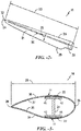
- Fig. 2 illustrates a perspective view of the rotor blade 16
- Fig. 3 illustrates a cross-sectional view of the rotor blade 16.
- the rotor blade 16 generally includes a blade root 30 configured to be mounted or otherwise secured to the hub 18 ( Fig. 1 ) of the wind turbine 10 and a blade tip 32 disposed opposite the blade root 30.
- a body shell 21 of the rotor blade 16 generally extends between the blade root 30 and the blade tip 32 along a longitudinal axis 27.
- the body shell 21 may generally serve as the outer casing/covering of the rotor blade 16 and may define a substantially aerodynamic profile, such as by defining a symmetrical or cambered airfoil-shaped cross-section.
- the body shell 21 may also define a pressure side 34 and a suction side 36 extending between leading and trailing ends 26, 28 of the rotor blade 16.
- the rotor blade 16 may also have a span 23 defining the total length between the blade root 30 and the blade tip 32 and a chord 25 defining the total length between the leading edge 26 and the trialing edge 28.
- the chord 25 may generally vary in length with respect to the span 23 as the rotor blade 16 extends from the blade root 30 to the blade tip 32.
- the body shell 21 of the rotor blade 16 may be formed as a single, unitary component.
- the body shell 21 may be formed from a plurality of shell components 22.
- the body shell 21 may be manufactured from a first shell half 22 generally defining the pressure side 34 of the rotor blade 16 and a second shell half 22 generally defining the suction side 36 of the rotor blade 16, with such shell halves being secured to one another at the leading and trailing ends 26, 28 of the blade 16.
- the body shell 21 may generally be formed from any suitable combination of materials.
- the body shell 21 may be formed entirely from a laminate composite material, such as a carbon fiber reinforced laminate composite or a glass fiber reinforced laminate composite.
- one or more portions of the body shell 21 may be configured as a layered construction and may include a core material, formed from a lightweight material such as wood (e.g., balsa), foam (e.g., extruded polystyrene foam) or a combination of such materials, disposed between layers of laminate composite material.
- a core material formed from a lightweight material such as wood (e.g., balsa), foam (e.g., extruded polystyrene foam) or a combination of such materials, disposed between layers of laminate composite material.
- the rotor blade 16 may also include one or more longitudinally extending structural components configured to provide increased stiffness, buckling resistance and/or strength to the rotor blade 16.
- the rotor blade 16 may include a pair of longitudinally extending spar caps 20 configured to be engaged against the opposing inner surfaces 35, 37 of the pressure and suction sides 34, 36 of the rotor blade 16, respectively.
- one or more shear webs 24 may be disposed between the spar caps 20 to form a beam-like configuration. Multiple I-beam structures may be used with respective spar caps 20 in accordance with aspects of the invention.
- the spar caps 20 may generally be designed to control the bending stresses and/or other loads acting on the rotor blade 16 in a generally spanwise direction (a direction parallel to the span 23 of the rotor blade 16) during operation of a wind turbine 10. Similarly, the spar caps 20 may also be designed to withstand the spanwise compression occurring during operation of the wind turbine 10.
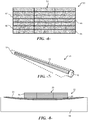
- Each of the spar caps 20 is depicted in Fig. 3 as formed from a stack of first and second pultrusion plates 42, 46, as discussed in greater detail below.
- the spar cap 20 includes a plurality of individual pultrusion plates 42, 46 in a stacked configuration 52, which may include a plurality of rows and columns of the plates 42, 46.
- Each plate 42, 46 is formed by a plurality of pultrusions bonded together in a generally plate-like shape having a width dimension and thickness dimension defined by opposite parallel sides, respectively.
- the plurality of plates within the stack 52 include one or more first pultrusion plates 42 formed from a first fiber material 44, such as glass fiber material pultrusions, and one or more second pultrusion plates 46 formed from a second fiber material 48, such as carbon (represented by the "C" in Fig. 4 ) fiber material pultrusions.
- first fiber material 44 such as glass fiber material pultrusions
- second fiber material 48 such as carbon (represented by the "C" in Fig. 4 ) fiber material pultrusions.
- the carbon pultrusion plates 48 have different (increased) strength characteristics as compared to the glass pultrusion plates 42, but can be significantly more expensive.
- the spar cap 20 can be designed with a stacked array 52 using both types of plates 42, 46 to achieve an overall desired strength and stiffness profile for the spar cap 20 while maximizing use of the glass pultrusion plates 42 to decrease costs.
- the present method and wind turbine blades 16 are not limited by the particular type of pultrusion fiber materials used to form the plates 42, 46, so long as two different types of materials are used to achieve an overall desired strength and stiffness profile for the spar cap 20.
- the first pultrusion fiber material 44 may be a glass fiber material
- the second pultrusion fiber material 48 may be a carbon fiber material.
- the first and second pultrusion plates 42, 46 have a continuous and unbroken length dimension corresponding to an entire length of the spar cap 20 for a wind turbine blade shell 21 (pressure and/or suction side shells), as depicted in Fig. 7 .
- the spar cap 20 is not formed by distinct span-wise sections of the plates 42, 46 joined together at one or more locations along the span 23 ( Fig. 2 ) of the blade 16, but has a bonded construction of continuous (span-wise) plates 42, 46.
- the first and second pultrusion plates 42, 46 are arranged in a stacked hybrid pattern 52 that contains both of the different pultrusion plates 42, 46 without bonding the plates together within the stack.
- the stacked hybrid pattern 52 can include any combination of rows and columns of the plates 42, 46.
- the stacked hybrid pattern 52 is then arranged on the interior side 35, 37 ( Fig. 3 ) of the blade shell 21 materials in a mold 54 for the blade shell ( Fig. 8 ).
- the stacked hybrid pattern 52 of first and second pultrusion plates 42, 46 are bonded with the blade shell 21 materials in a resin infusion process to form an integral blade shell component 22, as represented in Fig. 8 .
- the resin infusion process thus co-bonds the stacked hybrid pattern 52 of first and second pultrusion plates 42, 46 and blade shell materials 21.
- the stacked hybrid pattern 52 of plates 42, 46 may be pre-bonded together to essentially define a bonded spar cap 20 prior to being placed in the blade shell mold 54.
- the subsequent resin infusion process then bonds the pre-bonded spar cap 20 to the interior side 35, 37 of the blade shell 21.
- the stacked hybrid pattern 52 of plates 42, 46 may take on various configurations depending on the strength, stiffness, or local stability characteristics desired to be imparted to the spar cap 20.
- the stack is not limited by the number or rows or columns of the plates 42, 46.
- the spar cap 20 may taper in width and/or height dimension by decreasing the number of plates 42, 46 in these regions during the forming process.
- the first 42 and second 46 pultrusion plates may be arranged in a uniform checker-board hybrid pattern to provide a generally homogenous combination of strength characteristics to the spar cap 20.
- the second pultrusion plates 46 may be placed at a greater concentration along one or both of an outer side of the stacked hybrid pattern 52 adjacent the blade shell 21 materials 21 and/or an inner side of the stacked hybrid pattern 52 opposite from the blade shell 21 materials.
- one or more rows of plates at either ( Fig. 6 ) or both ( Fig. 5 ) of the outer sides of the stack 52 may be formed completely by the second pultrusion plates 46.
- the present invention also encompasses a wind turbine blade shell component 22 (pressure side 34 or suction side 36) that comprises a blade shell 21, and a spar cap 20 bonded to an interior surface 35, 37 of the blade shell in accordance with the aspects discussed above.
- the present invention also encompasses a wind turbine blade 16 having a pressure side shell 34 and a suction side shell 36, wherein the suction and pressure side shells are joined along a leading 26 and trailing edge 28 of the blade.
- One or both of the suction and pressure side shell components further include a spar cap 20 bonded to an interior surface 35, 37 of the shell, wherein the spar cap 20 includes first pultrusion plates 42 and second pultrusion plates 46 arranged in a stacked hybrid pattern 52, as discussed above.
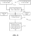
- Fig. 9 generally depicts a generic manufacturing method 100 in accordance with aspects of the invention.
- the first pultrusion plates 42 are formed.
- the second pultrusion plates 46 are formed. These steps may be carried out in concurrent inline processes.
- the first and second pultrusion plates 42, 46 are arranged in the desired stacked hybrid pattern 52.
- the stack 52 may remain unbounded (as discussed above), or may be bonded together.
- the pultrusion plates 42, 46 may be cut and prepared in the same step, or previously cut and prepared.
- the stacked hybrid pattern 52 is transported into the blade shell mold 54. It should be understood that steps 106 and 108 may be combined into a single step. In other words, the stack 52 may be formed directly in the blade mold 54.
- the stack 52 and blade shell materials are infused with resin to form a complete blade shell component 22 with full-length spar cap 20 bonded to an interior surface 35, 37 thereof. If the spar cap 20 was not pre-bonded, this step co-bonds the spar cap plates and blade shell materials in a single process step.
Description
- The present disclosure relates generally to wind turbines, and more particularly to wind turbine blades having a spar cap manufactured from pultruded plates.
- Wind power is considered one of the cleanest, most environmentally friendly energy sources presently available, and wind turbines have gained increased attention in this regard. A modern wind turbine typically includes a tower, generator, gearbox, nacelle, and one or more rotor blades. The rotor blades capture kinetic energy from wind using known foil principles and transmit the kinetic energy through rotational energy to turn a shaft coupling the rotor blades to a gearbox, or if a gearbox is not used, directly to the generator. The generator then converts the mechanical energy to electrical energy that may be deployed to a utility grid.
- Wind turbine rotor blades generally include a body shell formed by two shell halves of a composite laminate material. The shell halves are generally manufactured using molding processes and then coupled together along the corresponding ends of the rotor blade. In general, the body shell is relatively lightweight and has structural properties (e.g., stiffness, buckling resistance and strength) which are not configured to withstand the bending moments and other loads exerted on the rotor bade during operation. To increase the stiffness, buckling resistance and strength of the rotor blade, the body shell is typically reinforced using one or more structural components (e.g. opposing spar caps with a shear web configured therebetween) that engage the inner surfaces of the shell halves.
- The spar caps may be constructed of various materials, including glass fiber laminate composites and carbon fiber laminate composites. More specifically, modern spar caps are often constructed of pultruded composites that are less expensive than traditional composites, as the pultruded composites can be produced in thicker sections. The terms "pultruded composites," "pultrusions," or similar terms are generally used to define reinforced materials (e.g. fibers or woven or braided strands) that are impregnated with a resin and pulled through a heated stationary die such that the resin cures or undergoes polymerization. As such, the pultrusion process is typically characterized by a continuous process that produces composite parts having a constant cross-section. Thus, a plurality of pultrusions can be vacuum infused together in a mold to form the spar caps.
- The industry is seeking ways to incorporate pultrusions into the spar caps of wind turbine blades for the material and economic benefits of such materials. For example,
U.S. Patent Application Publication 2014/0271198 is directed to segmented wind turbine blades, wherein each blade segment includes a respective spar. The spars are connected together at spar joints, such as finger-type joints. The spar elements include planks manufactured as pultrusions, wherein first planks and second planks have different material compositions. -
US2016146184 A1 discloses methods of manufacturing rotor blade components for a wind turbine using pre-cured, prefabricated plates constructed of multiple fiber materials. -
US2017082089 A1 discloses a rotor blade component for a wind turbine rotor blade which may generally include an assembly of pre-formed pultruded products. -
EP3029314 A1 discloses rotor blade components for wind turbines having interlocking edges and methods of manufacturing same. -
US2017/080648 A1 discloses a method for manufacturing a spar cap for a wind turbine rotor blade which may generally include stacking a plurality of plates together to form a plate assembly. -
US2017/114773 A1 discloses pre-cured composites for use in manufacturing rotor blade components of a wind turbine. -
EP3112673 A1 discloses a spar cap for a rotor blade of a wind turbine which may generally include an assembly of pre-cured laminate plates stacked on one top of the other. - Accordingly, there is an ongoing need for an improved pultruded spar cap and method for incorporating such spar cap in a wind turbine blade, wherein such need may include optimizing the amount of more expensive and less expensive materials used in the spar cap to achieve a more cost efficient structure.
- Various aspects and advantages of the invention will be set forth in part in the following description, or may be clear from the description, or may be learned through practice of the invention.
- In one aspect, the present invention is directed to a method for manufacturing a wind turbine blade shell component according to claim 1 that includes providing a plurality of first pultrusion plates formed of a first pultrusion fiber material, and providing a plurality of second pultrusion plates formed of a second pultrusion fiber material. The first and second pultrusion plates have a length corresponding to an entire length of a spar cap for a wind turbine blade shell. The first and second pultrusion plates are stacked in a hybrid pattern that contains both of the different pultrusion plates. The stacked hybrid pattern of first and second pultrusion plates is arranged on blade shell material in a mold for the blade shell. Then, the stacked hybrid pattern of first and second pultrusion plates are bonded with the blade shell materials to form the blade shell component.
- In one embodiment, the stacked hybrid pattern of first and second pultrusion plates are bonded with the blade shell materials in a resin infusion process. In this process, the stacked hybrid pattern of first and second pultrusion plates may be un-bonded when arranged on the blade shell materials in the mold, wherein the bonding step includes co-bonding the stacked hybrid pattern of first and second pultrusion plates and blade shell materials by the resin infusion process. Alternatively, the stacked hybrid pattern of pultrusion plates may be pre-bonded together prior to placement in the blade mold.
- In a particular embodiment, the first pultrusion fiber material may be a glass fiber material, and the second pultrusion fiber material may be a carbon fiber material.
- The stacked hybrid pattern may take on various configurations depending on the strength characteristics desired to be imparted to the spar cap. For example, the first and second pultrusion plates may be arranged in a uniform checker-board hybrid pattern to provide a generally homogenous combination of strength characteristics. In an alternate embodiment, the second pultrusion plates may be placed at a greater concentration along one or both of an outer side of the stack adjacent the blade shell materials and an inner side of the stack opposite from the blade shell materials.
- The present invention also encompasses a wind turbine blade shell component according to claim 7 that comprises a blade shell, and a spar cap bonded to an interior surface of the blade shell. The spar cap is formed from first pultrusion plates and second pultrusion plates arranged in a stacked hybrid pattern, wherein the first and second pultrusion plates have a continuous unbroken length along an entire length of the spar cap.
- In a particular embodiment, the stacked hybrid pattern of first and second pultrusion plates are pre-bonded together prior to being bonded to the blade shell. Alternatively, the stacked hybrid pattern of first and second pultrusion plates are co-bonded with the blade shell materials.
- The first and second pultrusion plates are made of different respective fiber materials. For example, the first pultrusion fiber material may be a glass fiber material, and the second pultrusion fiber material may be a carbon fiber material.
- The present invention also encompasses a wind turbine blade having a pressure side shell and a suction side shell, wherein the suction and pressure side shells are joined along a leading and trailing edge of the blade. One or both of the suction and pressure side shell components further include a spar cap bonded to an interior surface of the shell, wherein the spar cap includes first pultrusion plates and second pultrusion plates arranged in a stacked hybrid pattern. The first and second pultrusion plates have a continuous unbroken length along an entire length of the spar cap.
- Various features, aspects and advantages of the present invention will become better understood with reference to the following description and appended claims. The accompanying drawings, which are incorporated in and constitute a part of this specification, illustrate embodiments of the invention and, together with the description, serve to explain the principles of the invention.
- In the drawings:
-
Fig. 1 is a perspective view of a conventional wind turbine; -
Fig. 2 is a perspective view of a conventional wind turbine blade; -
Fig. 3 is a side cross-sectional view of a wind turbine blade incorporating spar caps in accordance with the invention; -
Fig. 4 is an end diagram view of an embodiment of a spar cap in accordance with the present invention; -
Fig. 5 is an end diagram view of another embodiment of a spar cap in accordance with the present invention; -
Fig. 6 is an end diagram view of a further embodiment of a spar cap in accordance with the present invention; -
Fig. 7 is perspective view of a wind turbine blade with a continuous spar cap configuration in accordance with aspects of the invention; -
Fig. 8 is a partial cross-sectional view of shell member and spar cap; and -
Fig. 9 is a diagram of a method embodiment in accordance with the invention. - Reference now will be made in detail to embodiments of the invention, one or more examples of which are illustrated in the drawings. Each example is provided by way of explanation of the invention, not limitation of the invention. In fact, it will be apparent to those skilled in the art that various modifications and variations can be made in the present invention without departing from the scope or spirit of the invention. For instance, features illustrated or described as part of one embodiment can be used with another embodiment to yield a still further embodiment. Thus, it is intended that the present invention covers such modifications and variations as come within the scope of the appended claims and their equivalents.
- Referring now to the drawings,
Fig. 1 illustrates a perspective view of a horizontalaxis wind turbine 10. It should be appreciated that thewind turbine 10 may also be a vertical-axis wind turbine. As shown in the illustrated embodiment, thewind turbine 10 includes atower 12, anacelle 14 mounted on thetower 12, and arotor hub 18 that is coupled to thenacelle 14. Thetower 12 may be fabricated from tubular steel or other suitable material. Therotor hub 18 includes one ormore rotor blades 16 coupled to and extending radially outward from thehub 18. Therotor blades 16 rotate therotor hub 18 to enable kinetic energy to be transferred from the wind into usable mechanical energy, and subsequently, electrical energy. Specifically, thehub 18 may be rotatably coupled to an electric generator (not illustrated) positioned within thenacelle 14 for production of electrical energy. - Referring to
Figs. 2 and 3 , one of therotor blades 16 ofFig. 1 is illustrated in accordance with aspects of the present subject matter. In particular,Fig. 2 illustrates a perspective view of therotor blade 16, whereasFig. 3 illustrates a cross-sectional view of therotor blade 16. As shown, therotor blade 16 generally includes ablade root 30 configured to be mounted or otherwise secured to the hub 18 (Fig. 1 ) of thewind turbine 10 and ablade tip 32 disposed opposite theblade root 30. Abody shell 21 of therotor blade 16 generally extends between theblade root 30 and theblade tip 32 along a longitudinal axis 27. Thebody shell 21 may generally serve as the outer casing/covering of therotor blade 16 and may define a substantially aerodynamic profile, such as by defining a symmetrical or cambered airfoil-shaped cross-section. Thebody shell 21 may also define apressure side 34 and asuction side 36 extending between leading and trailing ends 26, 28 of therotor blade 16. Further, therotor blade 16 may also have aspan 23 defining the total length between theblade root 30 and theblade tip 32 and achord 25 defining the total length between theleading edge 26 and the trialingedge 28. As is generally understood, thechord 25 may generally vary in length with respect to thespan 23 as therotor blade 16 extends from theblade root 30 to theblade tip 32. - In several embodiments, the
body shell 21 of therotor blade 16 may be formed as a single, unitary component. Alternatively, thebody shell 21 may be formed from a plurality ofshell components 22. For example, thebody shell 21 may be manufactured from afirst shell half 22 generally defining thepressure side 34 of therotor blade 16 and asecond shell half 22 generally defining thesuction side 36 of therotor blade 16, with such shell halves being secured to one another at the leading and trailing ends 26, 28 of theblade 16. Additionally, thebody shell 21 may generally be formed from any suitable combination of materials. For instance, in one embodiment, thebody shell 21 may be formed entirely from a laminate composite material, such as a carbon fiber reinforced laminate composite or a glass fiber reinforced laminate composite. Alternatively, one or more portions of thebody shell 21 may be configured as a layered construction and may include a core material, formed from a lightweight material such as wood (e.g., balsa), foam (e.g., extruded polystyrene foam) or a combination of such materials, disposed between layers of laminate composite material. - Referring particularly to
Fig. 3 , therotor blade 16 may also include one or more longitudinally extending structural components configured to provide increased stiffness, buckling resistance and/or strength to therotor blade 16. For example, therotor blade 16 may include a pair of longitudinally extending spar caps 20 configured to be engaged against the opposinginner surfaces suction sides rotor blade 16, respectively. Additionally, one ormore shear webs 24 may be disposed between the spar caps 20 to form a beam-like configuration. Multiple I-beam structures may be used with respective spar caps 20 in accordance with aspects of the invention. The spar caps 20 may generally be designed to control the bending stresses and/or other loads acting on therotor blade 16 in a generally spanwise direction (a direction parallel to thespan 23 of the rotor blade 16) during operation of awind turbine 10. Similarly, the spar caps 20 may also be designed to withstand the spanwise compression occurring during operation of thewind turbine 10. Each of the spar caps 20 is depicted inFig. 3 as formed from a stack of first andsecond pultrusion plates - As discussed above, it is generally known in the art to form fiber material pultrusions into plates and to use such plates to form spar caps in wind turbine blades. For example,
U.S. Patent Application Publication 2017/0028587 (incorporated herein by reference for all purposes) describes an inline processing method and system for manufacturing pultruded plates that may be used in the method and system of the present invention. - Referring now to
Fig. 4 , a partial, cross-sectional or end view of one embodiment of aspar cap 20 according to the present invention is illustrated. Thespar cap 20 includes a plurality ofindividual pultrusion plates configuration 52, which may include a plurality of rows and columns of theplates plate stack 52 include one or morefirst pultrusion plates 42 formed from afirst fiber material 44, such as glass fiber material pultrusions, and one or moresecond pultrusion plates 46 formed from asecond fiber material 48, such as carbon (represented by the "C" inFig. 4 ) fiber material pultrusions. As is readily understood, thecarbon pultrusion plates 48 have different (increased) strength characteristics as compared to theglass pultrusion plates 42, but can be significantly more expensive. Thespar cap 20 can be designed with astacked array 52 using both types ofplates spar cap 20 while maximizing use of theglass pultrusion plates 42 to decrease costs. - It should be appreciated that the present method and
wind turbine blades 16 are not limited by the particular type of pultrusion fiber materials used to form theplates spar cap 20. In the embodiments described herein for illustrative purposes, the firstpultrusion fiber material 44 may be a glass fiber material, and the secondpultrusion fiber material 48 may be a carbon fiber material. - In a particular embodiment, the first and
second pultrusion plates spar cap 20 for a wind turbine blade shell 21 (pressure and/or suction side shells), as depicted inFig. 7 . In other words, thespar cap 20 is not formed by distinct span-wise sections of theplates Fig. 2 ) of theblade 16, but has a bonded construction of continuous (span-wise)plates - In one embodiment of the manufacturing method, the first and
second pultrusion plates hybrid pattern 52 that contains both of thedifferent pultrusion plates hybrid pattern 52 can include any combination of rows and columns of theplates hybrid pattern 52 is then arranged on theinterior side 35, 37 (Fig. 3 ) of theblade shell 21 materials in amold 54 for the blade shell (Fig. 8 ). Then, the stackedhybrid pattern 52 of first andsecond pultrusion plates blade shell 21 materials in a resin infusion process to form an integralblade shell component 22, as represented inFig. 8 . The resin infusion process thus co-bonds the stackedhybrid pattern 52 of first andsecond pultrusion plates blade shell materials 21. - In an alternate embodiment, the stacked
hybrid pattern 52 ofplates spar cap 20 prior to being placed in theblade shell mold 54. The subsequent resin infusion process then bonds thepre-bonded spar cap 20 to theinterior side blade shell 21. - The stacked
hybrid pattern 52 ofplates spar cap 20. The stack is not limited by the number or rows or columns of theplates root 30 orblade tip 32, thespar cap 20 may taper in width and/or height dimension by decreasing the number ofplates Fig. 4 , the first 42 and second 46 pultrusion plates may be arranged in a uniform checker-board hybrid pattern to provide a generally homogenous combination of strength characteristics to thespar cap 20. - In an alternate embodiment depicted in
Fig. 5 , thesecond pultrusion plates 46 may be placed at a greater concentration along one or both of an outer side of the stackedhybrid pattern 52 adjacent theblade shell 21materials 21 and/or an inner side of the stackedhybrid pattern 52 opposite from theblade shell 21 materials. For example, one or more rows of plates at either (Fig. 6 ) or both (Fig. 5 ) of the outer sides of thestack 52 may be formed completely by thesecond pultrusion plates 46. - As mentioned above, the present invention also encompasses a wind turbine blade shell component 22 (
pressure side 34 or suction side 36) that comprises ablade shell 21, and aspar cap 20 bonded to aninterior surface - The present invention also encompasses a
wind turbine blade 16 having apressure side shell 34 and asuction side shell 36, wherein the suction and pressure side shells are joined along a leading 26 and trailingedge 28 of the blade. One or both of the suction and pressure side shell components further include aspar cap 20 bonded to aninterior surface spar cap 20 includesfirst pultrusion plates 42 andsecond pultrusion plates 46 arranged in a stackedhybrid pattern 52, as discussed above. -
Fig. 9 generally depicts ageneric manufacturing method 100 in accordance with aspects of the invention. Atstep 102, thefirst pultrusion plates 42 are formed. - Likewise, at
step 104, thesecond pultrusion plates 46 are formed. These steps may be carried out in concurrent inline processes. - At
step 106, the first andsecond pultrusion plates hybrid pattern 52. Thestack 52 may remain unbounded (as discussed above), or may be bonded together. Thepultrusion plates - At
step 108, the stackedhybrid pattern 52 is transported into theblade shell mold 54. It should be understood thatsteps stack 52 may be formed directly in theblade mold 54. - At
step 110, thestack 52 and blade shell materials are infused with resin to form a completeblade shell component 22 with full-length spar cap 20 bonded to aninterior surface spar cap 20 was not pre-bonded, this step co-bonds the spar cap plates and blade shell materials in a single process step. - This written description uses examples to disclose the invention, including the preferred mode, and also to enable any person skilled in the art to practice the invention, including making and using any devices or systems and performing any incorporated methods. The patentable scope of the invention is defined by the claims.
Claims (13)
- A method (100) for manufacturing a wind turbine blade shell component (22), comprising:providing a plurality of first pultrusion plates (42) formed of a first pultrusion fiber material (44);providing a plurality of second pultrusion plates (46) formed of a second pultrusion fiber material (48);the first pultrusion plates (42) are different from the second pultrusion plates (46);the first and second pultrusion plates having a length corresponding to an entire length of a spar cap (20) for a wind turbine blade shell (21);stacking the first and second pultrusion plates in a hybrid pattern (52) that contains both first and second pultrusion plates;arranging the stacked hybrid pattern of first and second pultrusion plates on blade shell material (21) in a mold (54) for the blade shell component; andbonding the stacked hybrid pattern of first and second pultrusion plates with the blade shell materials to form the blade shell component.
- The method (100) of claim 1, wherein the stacked hybrid pattern (52) of first (42) and second (46) pultrusion plates are bonded with the blade shell material (21) in a resin infusion process.
- The method (100) of claim 2, wherein the stacked hybrid pattern (52) of first (42) and second (46) pultrusion plates are un-bonded when arranged on the blade shell material (21) in the mold (54), the bonding step comprising co-bonding the stacked hybrid pattern of first and second pultrusion plates and blade shell materials by the resin infusion process.
- The method (100) of any one of claims 1 to 3, wherein the first pultrusion fiber material (44) comprises a glass fiber material, and the second pultrusion fiber material (48) comprises a carbon fiber material.
- The method (100) of claim 4, wherein the first (42) and second (46) pultrusion plates are arranged in a uniform checker-board pattern in the stacked hybrid pattern (52).
- The method (100) of claim 4 or 5, wherein second pultrusion plates (46) have a greater concentration along one or both of an outer side of the stacked hybrid pattern (52) adjacent the blade shell material (21) and an inner side of the stacked hybrid pattern opposite from the blade shell material.
- A wind turbine blade shell component (22), comprising:a blade shell (21);a spar cap (20) bonded to an interior surface of the blade shell;the spar cap comprising first pultrusion plates (42) and second pultrusion plates (46) arranged in a stacked hybrid pattern (52), the first pultrusion plates (42) being formed of a first pultrusion fiber material (44) and the second pultrusion plates (46) being formed of a second pultrusion fiber material (48), wherein the first pultrusion plates (42) are different from the second pultrusion plates (46); andthe first and second pultrusion plates having a continuous unbroken length along an entire length of the spar cap.
- The wind turbine blade shell component (22) as in claim 7, wherein the first (42) and second (46) pultrusion plates are pre-bonded together in the stacked hybrid pattern (52) prior to being bonded to the blade shell (21).
- The wind turbine blade shell component (22) as in claim 7 or 8, wherein the stacked hybrid pattern (52) of first (42) and second (46) pultrusion plates are co-bonded with the blade shell material (21).
- The wind turbine blade shell component (22) as in any one of claims 7 to 9, wherein the first pultrusion fiber material (44) comprises a glass fiber material and the second pultrusion fiber material (48) comprises a carbon fiber material.
- The wind turbine blade shell component (22) as in claim 10, wherein the first (42) and second (46) pultrusion plates are arranged in a uniform checker-board pattern in the stacked hybrid pattern (52).
- The wind turbine blade shell component (22) as in claim 10 or 11, wherein the second pultrusion plates (46) have a greater concentration along one or both of an outer side of the stacked hybrid pattern (52) adjacent the blade shell material (21) and an inner side of the stacked hybrid pattern opposite from the blade shell material.
- A wind turbine blade (16), comprising a wind turbine blade shell component according to any of claims 7 - 12.
Applications Claiming Priority (1)
| Application Number | Priority Date | Filing Date | Title |
|---|---|---|---|
| US15/628,933 US10465653B2 (en) | 2017-06-21 | 2017-06-21 | Wind turbine blade with hybrid spar cap and associated method for making |
Publications (2)
| Publication Number | Publication Date |
|---|---|
| EP3418556A1 EP3418556A1 (en) | 2018-12-26 |
| EP3418556B1 true EP3418556B1 (en) | 2020-08-19 |
Family
ID=62597347
Family Applications (1)
| Application Number | Title | Priority Date | Filing Date |
|---|---|---|---|
| EP18176764.1A Active EP3418556B1 (en) | 2017-06-21 | 2018-06-08 | A wind turbine blade with hybrid spar cap and associated method for making |
Country Status (4)
| Country | Link |
|---|---|
| US (1) | US10465653B2 (en) |
| EP (1) | EP3418556B1 (en) |
| CN (1) | CN109094075A (en) |
| DK (1) | DK3418556T3 (en) |
Families Citing this family (11)
| Publication number | Priority date | Publication date | Assignee | Title |
|---|---|---|---|---|
| WO2021048403A1 (en) * | 2019-09-13 | 2021-03-18 | Siemens Gamesa Renewable Energy Innovation & Technology S.L. | Wind turbine blade |
| EP3792480A1 (en) * | 2019-09-13 | 2021-03-17 | Siemens Gamesa Renewable Energy Innovation & Technology, S.L. | Wind turbine blade |
| AU2020430267B2 (en) | 2020-02-18 | 2024-03-14 | Envision Energy Co., Ltd | Main beam for fan blade and manufacturing method therefor |
| US20230071090A1 (en) * | 2020-04-07 | 2023-03-09 | Lm Wind Power A/S | Main laminate |
| EP4136338A1 (en) * | 2020-04-15 | 2023-02-22 | LM Wind Power A/S | Reinforcing structure for a wind turbine blade |
| WO2021213651A1 (en) * | 2020-04-22 | 2021-10-28 | Blade Dynamics Limited | Alternative primer application method |
| GB2611677B (en) * | 2020-07-28 | 2024-04-03 | Envision Energy Co Ltd | Main beam for use in wind-driven generator blade and manufacturing method therefor |
| GB202017398D0 (en) * | 2020-11-03 | 2020-12-16 | Blade Dynamics Ltd | Hybrid pultrusion plates for a spar cap of a wind turbine blade |
| WO2022188934A1 (en) * | 2021-03-09 | 2022-09-15 | Vestas Wind Systems A/S | Wind turbine rotor blade spar cap with equipotential bonding |
| CN113074090B (en) * | 2021-03-31 | 2022-12-09 | 株洲时代新材料科技股份有限公司 | Carbon-glass hybrid wind power blade crossbeam and preparation method thereof |
| WO2023022715A1 (en) * | 2021-08-19 | 2023-02-23 | Lm Wind Power A/S | Winged spar cap configuration for a jointed wind turbine blade |
Citations (12)
| Publication number | Priority date | Publication date | Assignee | Title |
|---|---|---|---|---|
| WO2006082479A1 (en) | 2005-02-03 | 2006-08-10 | Vestas Wind Systems A/S | Method of manufacturing a wind turbine blade shell member |
| WO2009059604A1 (en) | 2007-11-09 | 2009-05-14 | Vestas Wind Systems A/S | A structural mat for reinforcing a wind turbine blade structure, a wind turbine blade and a method for manufacturing a wind turbine blade |
| US20100104447A1 (en) | 2006-02-13 | 2010-04-29 | General Electric Company | Carbon-glass-hybrid spar for wind turbine rotorblades |
| WO2011135306A1 (en) | 2010-04-30 | 2011-11-03 | Blade Dynamics Limited | A modular structural composite beam |
| WO2013087078A1 (en) | 2011-12-16 | 2013-06-20 | Vestas Wind Systems A/S | Wind turbine blades |
| US20140271198A1 (en) | 2013-03-13 | 2014-09-18 | Vestas Wind Systems A/S | Wind turbine blades with layered, multi-component spars, and associated systems and methods |
| WO2015009412A2 (en) | 2013-07-19 | 2015-01-22 | Wetzel Engineering, Inc. | Structural member with pultrusions |
| GB2526795A (en) | 2014-06-02 | 2015-12-09 | Vestas Wind Sys As | Wind turbines incorporating radar absorbing material |
| US20160146184A1 (en) | 2014-11-25 | 2016-05-26 | General Electric Company | Methods of manufacturing rotor blade components for a wind turbine |
| EP3029314A1 (en) | 2014-12-04 | 2016-06-08 | General Electric Company | Pultruded rotor blade components having interlocking edges |
| EP3112673A1 (en) | 2015-06-30 | 2017-01-04 | General Electric Company | Spar cap for a wind turbine rotor blade formed from pre-cured laminate plates of varying thicknesses |
| US20170080648A1 (en) | 2015-09-23 | 2017-03-23 | General Electric Company | Methods for manufacturing spar caps for wind turbine rotor blades using thermoplastic-based composite plates |
Family Cites Families (9)
| Publication number | Priority date | Publication date | Assignee | Title |
|---|---|---|---|---|
| DK2358998T3 (en) | 2008-12-05 | 2017-10-30 | Vestas Wind Sys As | EFFICIENT WINDOWS, WINDOWS, AND ASSOCIATED SYSTEMS AND PROCEDURES FOR MANUFACTURING, INSTALLING AND USING |
| US20110135485A1 (en) | 2009-12-30 | 2011-06-09 | Jing Wang | Spar for a wind turbine rotor blade and method for fabricating the same |
| US9822761B2 (en) * | 2014-08-13 | 2017-11-21 | General Electric Company | Structural components and methods of manufacturing |
| US20160146185A1 (en) | 2014-11-25 | 2016-05-26 | General Electric Company | Methods for manufacturing a spar cap for a wind turbine rotor blade |
| US9745956B2 (en) | 2014-12-10 | 2017-08-29 | General Electric Company | Spar cap for a wind turbine rotor blade |
| US20170028587A1 (en) | 2015-07-30 | 2017-02-02 | General Electric Company | In-line processing of pre-formed pultruded products for use within a wind turbine rotor blade |
| US10669984B2 (en) * | 2015-09-22 | 2020-06-02 | General Electric Company | Method for manufacturing blade components using pre-cured laminate materials |
| US10107257B2 (en) * | 2015-09-23 | 2018-10-23 | General Electric Company | Wind turbine rotor blade components formed from pultruded hybrid-resin fiber-reinforced composites |
| US10113532B2 (en) * | 2015-10-23 | 2018-10-30 | General Electric Company | Pre-cured composites for rotor blade components |
-
2017
- 2017-06-21 US US15/628,933 patent/US10465653B2/en active Active
-
2018
- 2018-06-08 EP EP18176764.1A patent/EP3418556B1/en active Active
- 2018-06-08 DK DK18176764.1T patent/DK3418556T3/en active
- 2018-06-21 CN CN201810644172.0A patent/CN109094075A/en active Pending
Patent Citations (12)
| Publication number | Priority date | Publication date | Assignee | Title |
|---|---|---|---|---|
| WO2006082479A1 (en) | 2005-02-03 | 2006-08-10 | Vestas Wind Systems A/S | Method of manufacturing a wind turbine blade shell member |
| US20100104447A1 (en) | 2006-02-13 | 2010-04-29 | General Electric Company | Carbon-glass-hybrid spar for wind turbine rotorblades |
| WO2009059604A1 (en) | 2007-11-09 | 2009-05-14 | Vestas Wind Systems A/S | A structural mat for reinforcing a wind turbine blade structure, a wind turbine blade and a method for manufacturing a wind turbine blade |
| WO2011135306A1 (en) | 2010-04-30 | 2011-11-03 | Blade Dynamics Limited | A modular structural composite beam |
| WO2013087078A1 (en) | 2011-12-16 | 2013-06-20 | Vestas Wind Systems A/S | Wind turbine blades |
| US20140271198A1 (en) | 2013-03-13 | 2014-09-18 | Vestas Wind Systems A/S | Wind turbine blades with layered, multi-component spars, and associated systems and methods |
| WO2015009412A2 (en) | 2013-07-19 | 2015-01-22 | Wetzel Engineering, Inc. | Structural member with pultrusions |
| GB2526795A (en) | 2014-06-02 | 2015-12-09 | Vestas Wind Sys As | Wind turbines incorporating radar absorbing material |
| US20160146184A1 (en) | 2014-11-25 | 2016-05-26 | General Electric Company | Methods of manufacturing rotor blade components for a wind turbine |
| EP3029314A1 (en) | 2014-12-04 | 2016-06-08 | General Electric Company | Pultruded rotor blade components having interlocking edges |
| EP3112673A1 (en) | 2015-06-30 | 2017-01-04 | General Electric Company | Spar cap for a wind turbine rotor blade formed from pre-cured laminate plates of varying thicknesses |
| US20170080648A1 (en) | 2015-09-23 | 2017-03-23 | General Electric Company | Methods for manufacturing spar caps for wind turbine rotor blades using thermoplastic-based composite plates |
Also Published As
| Publication number | Publication date |
|---|---|
| EP3418556A1 (en) | 2018-12-26 |
| CN109094075A (en) | 2018-12-28 |
| US10465653B2 (en) | 2019-11-05 |
| US20180372066A1 (en) | 2018-12-27 |
| DK3418556T3 (en) | 2020-11-16 |
Similar Documents
| Publication | Publication Date | Title |
|---|---|---|
| EP3418556B1 (en) | A wind turbine blade with hybrid spar cap and associated method for making | |
| EP3418557B1 (en) | A wind turbine blade with hybrid spar cap and associated method for making | |
| EP3029314B1 (en) | Pultruded rotor blade components having interlocking edges | |
| EP3026259A1 (en) | Methods for manufacturing a spar cap for a wind turbine rotor blade | |
| EP3112672B1 (en) | Modular rotor blade for wind turbine | |
| EP3026260A1 (en) | Methods of manufacturing rotor blade components for a wind turbine | |
| US9951750B2 (en) | Rotor blade with interior shelf for a flat plate spar cap | |
| EP3032092B1 (en) | Spar cap for a wind turbine rotor blade | |
| US10987879B2 (en) | Methods of manufacturing rotor blade components for a wind turbine | |
| EP3501810B1 (en) | Pultruded fibrous composite strips having corrugated profiles for wind turbine blade spar caps | |
| US10895244B2 (en) | Joint interface for wind turbine rotor blade components | |
| US10077758B2 (en) | Corrugated pre-cured laminate plates for use within wind turbine rotor blades | |
| EP3112668A1 (en) | Blade root section for a modular rotor blade and method of manufacturing same | |
| US10605227B2 (en) | Segmented wind turbine rotor blade with welded joint | |
| CN106321345B (en) | Spar cap for wind turbine rotor blade formed from pre-treated laminate | |
| DK178020B1 (en) | SAVE CAP UNIT FOR A WINDOW MILLER CIRCUIT | |
| EP3032094B1 (en) | Spar cap for a wind turbine rotor blade | |
| US20140119932A1 (en) | Structural members for a wind turbine rotor blade | |
| WO2019212554A1 (en) | Methods of manufacturing rotor blade components for a wind turbine | |
| CN117795190A (en) | Winged spar cap configuration for a spliced wind turbine blade |
Legal Events
| Date | Code | Title | Description |
|---|---|---|---|
| PUAI | Public reference made under article 153(3) epc to a published international application that has entered the european phase |
Free format text: ORIGINAL CODE: 0009012 |
|
| STAA | Information on the status of an ep patent application or granted ep patent |
Free format text: STATUS: THE APPLICATION HAS BEEN PUBLISHED |
|
| AK | Designated contracting states |
Kind code of ref document: A1 Designated state(s): AL AT BE BG CH CY CZ DE DK EE ES FI FR GB GR HR HU IE IS IT LI LT LU LV MC MK MT NL NO PL PT RO RS SE SI SK SM TR |
|
| AX | Request for extension of the european patent |
Extension state: BA ME |
|
| STAA | Information on the status of an ep patent application or granted ep patent |
Free format text: STATUS: REQUEST FOR EXAMINATION WAS MADE |
|
| 17P | Request for examination filed |
Effective date: 20190626 |
|
| RBV | Designated contracting states (corrected) |
Designated state(s): AL AT BE BG CH CY CZ DE DK EE ES FI FR GB GR HR HU IE IS IT LI LT LU LV MC MK MT NL NO PL PT RO RS SE SI SK SM TR |
|
| GRAP | Despatch of communication of intention to grant a patent |
Free format text: ORIGINAL CODE: EPIDOSNIGR1 |
|
| STAA | Information on the status of an ep patent application or granted ep patent |
Free format text: STATUS: GRANT OF PATENT IS INTENDED |
|
| RIC1 | Information provided on ipc code assigned before grant |
Ipc: F03D 13/10 20160101ALI20200124BHEP Ipc: B29C 70/52 20060101ALI20200124BHEP Ipc: F03D 1/06 20060101AFI20200124BHEP Ipc: B29D 99/00 20100101ALI20200124BHEP |
|
| INTG | Intention to grant announced |
Effective date: 20200213 |
|
| GRAS | Grant fee paid |
Free format text: ORIGINAL CODE: EPIDOSNIGR3 |
|
| GRAJ | Information related to disapproval of communication of intention to grant by the applicant or resumption of examination proceedings by the epo deleted |
Free format text: ORIGINAL CODE: EPIDOSDIGR1 |
|
| GRAL | Information related to payment of fee for publishing/printing deleted |
Free format text: ORIGINAL CODE: EPIDOSDIGR3 |
|
| STAA | Information on the status of an ep patent application or granted ep patent |
Free format text: STATUS: REQUEST FOR EXAMINATION WAS MADE |
|
| GRAR | Information related to intention to grant a patent recorded |
Free format text: ORIGINAL CODE: EPIDOSNIGR71 |
|
| STAA | Information on the status of an ep patent application or granted ep patent |
Free format text: STATUS: GRANT OF PATENT IS INTENDED |
|
| INTC | Intention to grant announced (deleted) | ||
| GRAA | (expected) grant |
Free format text: ORIGINAL CODE: 0009210 |
|
| STAA | Information on the status of an ep patent application or granted ep patent |
Free format text: STATUS: THE PATENT HAS BEEN GRANTED |
|
| AK | Designated contracting states |
Kind code of ref document: B1 Designated state(s): AL AT BE BG CH CY CZ DE DK EE ES FI FR GB GR HR HU IE IS IT LI LT LU LV MC MK MT NL NO PL PT RO RS SE SI SK SM TR |
|
| INTG | Intention to grant announced |
Effective date: 20200710 |
|
| REG | Reference to a national code |
Ref country code: CH Ref legal event code: EP |
|
| REG | Reference to a national code |
Ref country code: DE Ref legal event code: R096 Ref document number: 602018006998 Country of ref document: DE |
|
| REG | Reference to a national code |
Ref country code: AT Ref legal event code: REF Ref document number: 1304207 Country of ref document: AT Kind code of ref document: T Effective date: 20200915 |
|
| REG | Reference to a national code |
Ref country code: IE Ref legal event code: FG4D |
|
| REG | Reference to a national code |
Ref country code: DK Ref legal event code: T3 Effective date: 20201110 |
|
| REG | Reference to a national code |
Ref country code: LT Ref legal event code: MG4D |
|
| REG | Reference to a national code |
Ref country code: NL Ref legal event code: MP Effective date: 20200819 |
|
| PG25 | Lapsed in a contracting state [announced via postgrant information from national office to epo] |
Ref country code: GR Free format text: LAPSE BECAUSE OF FAILURE TO SUBMIT A TRANSLATION OF THE DESCRIPTION OR TO PAY THE FEE WITHIN THE PRESCRIBED TIME-LIMIT Effective date: 20201120 Ref country code: LT Free format text: LAPSE BECAUSE OF FAILURE TO SUBMIT A TRANSLATION OF THE DESCRIPTION OR TO PAY THE FEE WITHIN THE PRESCRIBED TIME-LIMIT Effective date: 20200819 Ref country code: HR Free format text: LAPSE BECAUSE OF FAILURE TO SUBMIT A TRANSLATION OF THE DESCRIPTION OR TO PAY THE FEE WITHIN THE PRESCRIBED TIME-LIMIT Effective date: 20200819 Ref country code: SE Free format text: LAPSE BECAUSE OF FAILURE TO SUBMIT A TRANSLATION OF THE DESCRIPTION OR TO PAY THE FEE WITHIN THE PRESCRIBED TIME-LIMIT Effective date: 20200819 Ref country code: BG Free format text: LAPSE BECAUSE OF FAILURE TO SUBMIT A TRANSLATION OF THE DESCRIPTION OR TO PAY THE FEE WITHIN THE PRESCRIBED TIME-LIMIT Effective date: 20201119 Ref country code: FI Free format text: LAPSE BECAUSE OF FAILURE TO SUBMIT A TRANSLATION OF THE DESCRIPTION OR TO PAY THE FEE WITHIN THE PRESCRIBED TIME-LIMIT Effective date: 20200819 Ref country code: PT Free format text: LAPSE BECAUSE OF FAILURE TO SUBMIT A TRANSLATION OF THE DESCRIPTION OR TO PAY THE FEE WITHIN THE PRESCRIBED TIME-LIMIT Effective date: 20201221 Ref country code: NO Free format text: LAPSE BECAUSE OF FAILURE TO SUBMIT A TRANSLATION OF THE DESCRIPTION OR TO PAY THE FEE WITHIN THE PRESCRIBED TIME-LIMIT Effective date: 20201119 |
|
| REG | Reference to a national code |
Ref country code: AT Ref legal event code: MK05 Ref document number: 1304207 Country of ref document: AT Kind code of ref document: T Effective date: 20200819 |
|
| PG25 | Lapsed in a contracting state [announced via postgrant information from national office to epo] |
Ref country code: RS Free format text: LAPSE BECAUSE OF FAILURE TO SUBMIT A TRANSLATION OF THE DESCRIPTION OR TO PAY THE FEE WITHIN THE PRESCRIBED TIME-LIMIT Effective date: 20200819 Ref country code: LV Free format text: LAPSE BECAUSE OF FAILURE TO SUBMIT A TRANSLATION OF THE DESCRIPTION OR TO PAY THE FEE WITHIN THE PRESCRIBED TIME-LIMIT Effective date: 20200819 Ref country code: NL Free format text: LAPSE BECAUSE OF FAILURE TO SUBMIT A TRANSLATION OF THE DESCRIPTION OR TO PAY THE FEE WITHIN THE PRESCRIBED TIME-LIMIT Effective date: 20200819 Ref country code: PL Free format text: LAPSE BECAUSE OF FAILURE TO SUBMIT A TRANSLATION OF THE DESCRIPTION OR TO PAY THE FEE WITHIN THE PRESCRIBED TIME-LIMIT Effective date: 20200819 Ref country code: IS Free format text: LAPSE BECAUSE OF FAILURE TO SUBMIT A TRANSLATION OF THE DESCRIPTION OR TO PAY THE FEE WITHIN THE PRESCRIBED TIME-LIMIT Effective date: 20201219 |
|
| PG25 | Lapsed in a contracting state [announced via postgrant information from national office to epo] |
Ref country code: EE Free format text: LAPSE BECAUSE OF FAILURE TO SUBMIT A TRANSLATION OF THE DESCRIPTION OR TO PAY THE FEE WITHIN THE PRESCRIBED TIME-LIMIT Effective date: 20200819 Ref country code: RO Free format text: LAPSE BECAUSE OF FAILURE TO SUBMIT A TRANSLATION OF THE DESCRIPTION OR TO PAY THE FEE WITHIN THE PRESCRIBED TIME-LIMIT Effective date: 20200819 Ref country code: CZ Free format text: LAPSE BECAUSE OF FAILURE TO SUBMIT A TRANSLATION OF THE DESCRIPTION OR TO PAY THE FEE WITHIN THE PRESCRIBED TIME-LIMIT Effective date: 20200819 Ref country code: SM Free format text: LAPSE BECAUSE OF FAILURE TO SUBMIT A TRANSLATION OF THE DESCRIPTION OR TO PAY THE FEE WITHIN THE PRESCRIBED TIME-LIMIT Effective date: 20200819 |
|
| REG | Reference to a national code |
Ref country code: DE Ref legal event code: R026 Ref document number: 602018006998 Country of ref document: DE |
|
| PLBI | Opposition filed |
Free format text: ORIGINAL CODE: 0009260 |
|
| PG25 | Lapsed in a contracting state [announced via postgrant information from national office to epo] |
Ref country code: AL Free format text: LAPSE BECAUSE OF FAILURE TO SUBMIT A TRANSLATION OF THE DESCRIPTION OR TO PAY THE FEE WITHIN THE PRESCRIBED TIME-LIMIT Effective date: 20200819 Ref country code: AT Free format text: LAPSE BECAUSE OF FAILURE TO SUBMIT A TRANSLATION OF THE DESCRIPTION OR TO PAY THE FEE WITHIN THE PRESCRIBED TIME-LIMIT Effective date: 20200819 Ref country code: ES Free format text: LAPSE BECAUSE OF FAILURE TO SUBMIT A TRANSLATION OF THE DESCRIPTION OR TO PAY THE FEE WITHIN THE PRESCRIBED TIME-LIMIT Effective date: 20200819 |
|
| PLAX | Notice of opposition and request to file observation + time limit sent |
Free format text: ORIGINAL CODE: EPIDOSNOBS2 |
|
| 26 | Opposition filed |
Opponent name: VESTAS WIND SYSTEMS A/S Effective date: 20210517 |
|
| PG25 | Lapsed in a contracting state [announced via postgrant information from national office to epo] |
Ref country code: SK Free format text: LAPSE BECAUSE OF FAILURE TO SUBMIT A TRANSLATION OF THE DESCRIPTION OR TO PAY THE FEE WITHIN THE PRESCRIBED TIME-LIMIT Effective date: 20200819 |
|
| PG25 | Lapsed in a contracting state [announced via postgrant information from national office to epo] |
Ref country code: IT Free format text: LAPSE BECAUSE OF FAILURE TO SUBMIT A TRANSLATION OF THE DESCRIPTION OR TO PAY THE FEE WITHIN THE PRESCRIBED TIME-LIMIT Effective date: 20200819 |
|
| PG25 | Lapsed in a contracting state [announced via postgrant information from national office to epo] |
Ref country code: SI Free format text: LAPSE BECAUSE OF FAILURE TO SUBMIT A TRANSLATION OF THE DESCRIPTION OR TO PAY THE FEE WITHIN THE PRESCRIBED TIME-LIMIT Effective date: 20200819 |
|
| PLBB | Reply of patent proprietor to notice(s) of opposition received |
Free format text: ORIGINAL CODE: EPIDOSNOBS3 |
|
| PG25 | Lapsed in a contracting state [announced via postgrant information from national office to epo] |
Ref country code: MC Free format text: LAPSE BECAUSE OF FAILURE TO SUBMIT A TRANSLATION OF THE DESCRIPTION OR TO PAY THE FEE WITHIN THE PRESCRIBED TIME-LIMIT Effective date: 20200819 |
|
| REG | Reference to a national code |
Ref country code: CH Ref legal event code: PL |
|
| REG | Reference to a national code |
Ref country code: BE Ref legal event code: MM Effective date: 20210630 |
|
| PG25 | Lapsed in a contracting state [announced via postgrant information from national office to epo] |
Ref country code: LU Free format text: LAPSE BECAUSE OF NON-PAYMENT OF DUE FEES Effective date: 20210608 |
|
| PG25 | Lapsed in a contracting state [announced via postgrant information from national office to epo] |
Ref country code: LI Free format text: LAPSE BECAUSE OF NON-PAYMENT OF DUE FEES Effective date: 20210630 Ref country code: IE Free format text: LAPSE BECAUSE OF NON-PAYMENT OF DUE FEES Effective date: 20210608 Ref country code: CH Free format text: LAPSE BECAUSE OF NON-PAYMENT OF DUE FEES Effective date: 20210630 |
|
| PG25 | Lapsed in a contracting state [announced via postgrant information from national office to epo] |
Ref country code: BE Free format text: LAPSE BECAUSE OF NON-PAYMENT OF DUE FEES Effective date: 20210630 |
|
| APAH | Appeal reference modified |
Free format text: ORIGINAL CODE: EPIDOSCREFNO |
|
| APBM | Appeal reference recorded |
Free format text: ORIGINAL CODE: EPIDOSNREFNO |
|
| APBP | Date of receipt of notice of appeal recorded |
Free format text: ORIGINAL CODE: EPIDOSNNOA2O |
|
| APBM | Appeal reference recorded |
Free format text: ORIGINAL CODE: EPIDOSNREFNO |
|
| APBP | Date of receipt of notice of appeal recorded |
Free format text: ORIGINAL CODE: EPIDOSNNOA2O |
|
| P01 | Opt-out of the competence of the unified patent court (upc) registered |
Effective date: 20230522 |
|
| PG25 | Lapsed in a contracting state [announced via postgrant information from national office to epo] |
Ref country code: CY Free format text: LAPSE BECAUSE OF FAILURE TO SUBMIT A TRANSLATION OF THE DESCRIPTION OR TO PAY THE FEE WITHIN THE PRESCRIBED TIME-LIMIT Effective date: 20200819 |
|
| APBQ | Date of receipt of statement of grounds of appeal recorded |
Free format text: ORIGINAL CODE: EPIDOSNNOA3O |
|
| APBQ | Date of receipt of statement of grounds of appeal recorded |
Free format text: ORIGINAL CODE: EPIDOSNNOA3O |
|
| PG25 | Lapsed in a contracting state [announced via postgrant information from national office to epo] |
Ref country code: HU Free format text: LAPSE BECAUSE OF FAILURE TO SUBMIT A TRANSLATION OF THE DESCRIPTION OR TO PAY THE FEE WITHIN THE PRESCRIBED TIME-LIMIT; INVALID AB INITIO Effective date: 20180608 |
|
| PGFP | Annual fee paid to national office [announced via postgrant information from national office to epo] |
Ref country code: FR Payment date: 20230523 Year of fee payment: 6 Ref country code: DK Payment date: 20230523 Year of fee payment: 6 Ref country code: DE Payment date: 20230523 Year of fee payment: 6 |
|
| PGFP | Annual fee paid to national office [announced via postgrant information from national office to epo] |
Ref country code: TR Payment date: 20230526 Year of fee payment: 6 |
|
| PGFP | Annual fee paid to national office [announced via postgrant information from national office to epo] |
Ref country code: GB Payment date: 20230523 Year of fee payment: 6 |
|
| REG | Reference to a national code |
Ref country code: GB Ref legal event code: 732E Free format text: REGISTERED BETWEEN 20231123 AND 20231129 |
|
| REG | Reference to a national code |
Ref country code: DE Ref legal event code: R081 Ref document number: 602018006998 Country of ref document: DE Owner name: LM WIND POWER A/S, DK Free format text: FORMER OWNER: GENERAL ELECTRIC COMPANY, SCHENECTADY, N.Y., US |