EP3501239B1 - Mikrowellenofen mit generatorstromversorgung - Google Patents
Mikrowellenofen mit generatorstromversorgung Download PDFInfo
- Publication number
- EP3501239B1 EP3501239B1 EP16914336.9A EP16914336A EP3501239B1 EP 3501239 B1 EP3501239 B1 EP 3501239B1 EP 16914336 A EP16914336 A EP 16914336A EP 3501239 B1 EP3501239 B1 EP 3501239B1
- Authority
- EP
- European Patent Office
- Prior art keywords
- energy reserve
- converter
- power
- generator
- microwave oven
- Prior art date
- Legal status (The legal status is an assumption and is not a legal conclusion. Google has not performed a legal analysis and makes no representation as to the accuracy of the status listed.)
- Active
Links
Images


Classifications
-
- H—ELECTRICITY
- H05—ELECTRIC TECHNIQUES NOT OTHERWISE PROVIDED FOR
- H05B—ELECTRIC HEATING; ELECTRIC LIGHT SOURCES NOT OTHERWISE PROVIDED FOR; CIRCUIT ARRANGEMENTS FOR ELECTRIC LIGHT SOURCES, IN GENERAL
- H05B6/00—Heating by electric, magnetic or electromagnetic fields
- H05B6/64—Heating using microwaves
- H05B6/76—Prevention of microwave leakage, e.g. door sealings
-
- H—ELECTRICITY
- H05—ELECTRIC TECHNIQUES NOT OTHERWISE PROVIDED FOR
- H05B—ELECTRIC HEATING; ELECTRIC LIGHT SOURCES NOT OTHERWISE PROVIDED FOR; CIRCUIT ARRANGEMENTS FOR ELECTRIC LIGHT SOURCES, IN GENERAL
- H05B6/00—Heating by electric, magnetic or electromagnetic fields
- H05B6/64—Heating using microwaves
- H05B6/6414—Aspects relating to the door of the microwave heating apparatus
- H05B6/6417—Door interlocks of the microwave heating apparatus and related circuits
-
- H—ELECTRICITY
- H02—GENERATION; CONVERSION OR DISTRIBUTION OF ELECTRIC POWER
- H02M—APPARATUS FOR CONVERSION BETWEEN AC AND AC, BETWEEN AC AND DC, OR BETWEEN DC AND DC, AND FOR USE WITH MAINS OR SIMILAR POWER SUPPLY SYSTEMS; CONVERSION OF DC OR AC INPUT POWER INTO SURGE OUTPUT POWER; CONTROL OR REGULATION THEREOF
- H02M1/00—Details of apparatus for conversion
- H02M1/32—Means for protecting converters other than automatic disconnection
- H02M1/322—Means for rapidly discharging a capacitor of the converter for protecting electrical components or for preventing electrical shock
-
- H—ELECTRICITY
- H05—ELECTRIC TECHNIQUES NOT OTHERWISE PROVIDED FOR
- H05B—ELECTRIC HEATING; ELECTRIC LIGHT SOURCES NOT OTHERWISE PROVIDED FOR; CIRCUIT ARRANGEMENTS FOR ELECTRIC LIGHT SOURCES, IN GENERAL
- H05B6/00—Heating by electric, magnetic or electromagnetic fields
- H05B6/64—Heating using microwaves
- H05B6/66—Circuits
- H05B6/68—Circuits for monitoring or control
- H05B6/686—Circuits comprising a signal generator and power amplifier, e.g. using solid state oscillators
-
- H—ELECTRICITY
- H02—GENERATION; CONVERSION OR DISTRIBUTION OF ELECTRIC POWER
- H02M—APPARATUS FOR CONVERSION BETWEEN AC AND AC, BETWEEN AC AND DC, OR BETWEEN DC AND DC, AND FOR USE WITH MAINS OR SIMILAR POWER SUPPLY SYSTEMS; CONVERSION OF DC OR AC INPUT POWER INTO SURGE OUTPUT POWER; CONTROL OR REGULATION THEREOF
- H02M1/00—Details of apparatus for conversion
- H02M1/0067—Converter structures employing plural converter units, other than for parallel operation of the units on a single load
- H02M1/007—Plural converter units in cascade
-
- H—ELECTRICITY
- H05—ELECTRIC TECHNIQUES NOT OTHERWISE PROVIDED FOR
- H05B—ELECTRIC HEATING; ELECTRIC LIGHT SOURCES NOT OTHERWISE PROVIDED FOR; CIRCUIT ARRANGEMENTS FOR ELECTRIC LIGHT SOURCES, IN GENERAL
- H05B2206/00—Aspects relating to heating by electric, magnetic, or electromagnetic fields covered by group H05B6/00
- H05B2206/04—Heating using microwaves
- H05B2206/046—Microwave drying of wood, ink, food, ceramic, sintering of ceramic, clothes, hair
-
- H—ELECTRICITY
- H05—ELECTRIC TECHNIQUES NOT OTHERWISE PROVIDED FOR
- H05B—ELECTRIC HEATING; ELECTRIC LIGHT SOURCES NOT OTHERWISE PROVIDED FOR; CIRCUIT ARRANGEMENTS FOR ELECTRIC LIGHT SOURCES, IN GENERAL
- H05B6/00—Heating by electric, magnetic or electromagnetic fields
- H05B6/64—Heating using microwaves
- H05B6/66—Circuits
- H05B6/68—Circuits for monitoring or control
Definitions
- the present disclosure generally relates to a cooking apparatus, and more particularly, to a microwave oven having a gnerator power supply unit with a discharge function.
- a conventional microwave oven cooks food by a process of dielectric heating in which a high-frequency alternating electromagnetic field is distributed throughout an enclosed cavity.
- a sub-band of the radio frequency spectrum microwave frequencies at or around 2.45 GHz cause dielectric heating primarily by absorption of energy in water.
- microwave ovens include, among other things, mechanical solutions such as a microwave stirrer and a turntable for rotating the food.
- a common magnetron-based microwave source is not narrowband and not tunable (i.e. emits microwaves at a frequency that is changing over time and not selectable).
- solid-state sources can be included in microwave ovens which are tunable and coherent.
- WO-A-2015/099649 discloses a microwave oven having a microwave generator, a generator power supply, a power source and a controller.
- the generator power supply includes a first interrupting circuit for interrupting power between the power source and an AC-DC power converter, and a second interrupting circuit for interrupting power from a second energy for interrupting power from a second energy reserve to RF amplifiers.
- a microwave oven is provided in accordance with claim 1.
- a method of operating a microwave oven to reduce microwave leakage is provided in accordance with claim 10.
- the term "and/or,” when used in a list of two or more items, means that any one of the listed items can be employed by itself, or any combination of two or more of the listed items can be employed.
- the composition can contain A alone; B alone; C alone; A and B in combination; A and C in combination; B and C in combination; or A, B, and C in combination.
- the present disclosure may be implemented in any environment using a radio frequency (RF) generator or amplifier capable of generating a field of electromagnetic radiation (e-field) in the radio frequency spectrum regardless of the application of the e-field and regardless of the frequency or frequency range of the e-field.
- RF radio frequency
- any e-field generating device for example, a microwave generator or infrared signal generator, will be generally referred to as an RF generator, or similar language
- any e-field applying device such as a waveguide, an antenna, or anode/cathode coupling or pair, will be generally referred to as an RF applicator.
- FIG. 1 schematically illustrates an RF device in the form of a microwave oven 10 including a cabinet 12 defining a cavity 14 for electromagnetically heating and/or cooking food, or foodstuff, in the cavity 14.
- the microwave oven 10 also includes a door 16 movably mounted to the cabinet 12, an RF shielding layer, for example, wire mesh 18, removably or fixedly attached to the cabinet 12 and the door 16.
- the door 16 is movable between an opened state and a closed state to selectively provide access to the cavity 14, for instance, to allow for inserting food items to be cooked or for removing food items previously cooked.
- the door 16 and corresponding segment of the wire mesh 18 are configured to align with the cabinet 12 to effectively prevent access to, and/or effectively seal, the cavity 14.
- the cavity 14 is further sealed due to the configuration of the wire mesh 18, which operates to prevent e-field leakage into, or out of, the cabinet 12 and cavity 14.
- the microwave oven 10 further includes a microwave generator shown as an RF generator 24 having at least one RF amplifier, shown as a first solid state RF amplifier 26 and a second solid state RF amplifier 28.
- the microwave oven 10 further includes at least one RF applicator, shown as a first RF applicator 30 and a second RF applicator 32, each of which is configured to apply an e-field 34 to the cavity 14.
- the microwave oven 10 also includes a generator power supply unit 36, an interruption circuit 37, a power source 38 (e.g., mains power), and a controller 40.
- the cavity 14 is shown to include the RF generator 24 and the first and second RF applicators 30, 32 located in opposing corners of the cavity 14, other embodiments contemplate alternative placements of the RF generator 24 and the first and second RF applicators 30, 32, including a configuration where the RF generator 24 and the first and second RF applicators 30, 32 are located outside of the cavity 14.
- the first and second RF applicators 30, 32 are waveguides that feed an e-field into the cavity 14.
- generator power supply unit 36, interruption circuit 37, power source 38, and controller 40 are generally shown outside of the cabinet 12, they are collectively contemplated to be included as components of the oven 10, and various placements of the aforementioned components are contemplated, which may include placement within the cavity 14, cabinet 12, and/or wire mesh 18.
- the first solid state RF amplifier 26 may be electrically coupled with the first RF applicator 30 and the second solid state RF amplifier 28 may be electrically coupled with the second RF applicator 32.
- the RF generator 24 may also be electrically coupled with the generator power supply unit 36, which may further be electrically coupled to the power source 38 via the interruption circuit 37.
- the interruption circuit 37 is configured to electrically couple the power source 38 to the generator power supply unit 36 when the door 16 is in a closed state and electrically decouple the power source 38 to the generator power supply unit 36 when the door 16 is in an open state. Accordingly, the interruption circuit 37 may be electrically coupled to a door switch, shown as door switch 41, which is configured to provide a signal indicative of a state of the door 16 to the interruption circuit 37.
- the controller 40 is shown communicatively coupled (illustrated as dotted lines) to the RF generator 24 and the generator power supply unit 36. In operation, the controller 40 may provide communication signals to one or more of the foregoing components for controlling the operation thereof.
- the RF generator 24 is configured to receive a power input from the generator power supply unit 36 and may generate one, two, three, four, or any number of RF signals, as needed by the particular oven application.
- the RF generator 24 is further configured to deliver each respective signal to a corresponding RF amplifier 26, 28.
- the RF generator 24 is capable of generating two RF signals, each of which is delivered to the corresponding first and second solid state RF amplifiers 26, 28 such that each of the first and second solid state RF amplifiers 26, 28 amplifies an independent RF signal.
- each RF signal may correspond to at least one of the first and second RF amplifiers 26, 28.
- one RF signal may correspond to one RF amplifier
- two RF signals may correspond to two respective RF amplifiers
- three RF signals may correspond to three respective RF amplifiers
- four RF signals may correspond to four respective RF amplifiers, and so on and so forth.
- one RF signal may correspond to, for example, two, three, or four RF amplifiers, such that each RF amplifier amplifies the same RF signal. Accordingly, it should be appreciated that any number of combinations and/or permutations of any number of RF signals and/or RF amplifiers as described are contemplated.
- Each of the first and second RF amplifiers 26, 28 may be correspondingly configured to deliver the amplified signal to the one or more RF applicators 30, 32, which are configured to direct the amplified RF signal, shown as an e-field 34, into the cavity 14.
- the generator power supply unit 36 may be additionally configured to operatively convert power received from the power source 38 to an alternative power output.
- the generator power supply unit 36 may be configured to convert an alternating current (AC) power input to a high current, low voltage direct current (DC) power output.
- AC alternating current
- DC direct current
- the controller 40 may be any appropriate device that is capable of receiving input signals, generating, processing, and/or determining commands, and providing the commands and/or command signals based on said commands, as one or more outputs.
- the controller 40 may include one or more programmable logic devices, application specific integrated circuits, digital signal processors, and/or microcontrollers.
- the controller 40 operates to control the microwave oven 10 such that the power source 38 provides a power input to the generator power supply unit 36, which is controlled to convert the power input from the power source 38 to a sufficient power output delivered to the RF generator 24.
- the generator power supply unit 36 may include, for instance, converting an AC power input to a low voltage (DC) output.
- the RF generator 24 may generate a radio frequency electromagnetic radiation (e-field) signal, which may be significantly or trivially amplified by each respective first and second RF amplifier 26, 28, and delivered from each first and second RF amplifier 26, 28 to the respective first and second RF applicators 30, 32 for application of the electromagnetic radiation to the cavity 14.
- e-field radio frequency electromagnetic radiation
- FIG. 2 schematically illustrates the power source 38, the interruption circuit 37, the generator power supply unit 36, and the RF generator 24 in further detail.
- the generator power supply unit 36 includes, as components, a bridge rectifier 44, at least one converter shown as a first converter 46 and a second converter 48, and at least one energy reserve shown as a first energy reserve 50 and a second energy reserve 52.
- the aforementioned components are shown ordered in a linear arrangement to more clearly illustrate the direction of power transfer, beginning at the power source 38, then moving across the components from an upstream to downstream direction (i.e., from left to right in FIG. 2 ), and ultimately ending at the RF generator 24.
- the components of the generator power supply unit 36 are positioned on a voltage line 56 and a ground line 58, both of which also serving to electrically connect the power source 38, the generator power supply unit 36, and the RF generator 24.
- a detection circuit 54 is illustrated as being a component of the generator power supply unit 36, it should be appreciated that the detection circuit 54 may be separately provided in other embodiments. With respect to any of the embodiments described herein, operation of the detection circuit 54 may be based on a state of the door 16.
- the interruption circuit 37 electrically couples the power source 38 to the generator power supply unit 36 while in a closed state, and electrically decouples the power source 38 to the generator supply 36 while in an open state.
- the power input provided by the power source 38 to the generator power supply unit 36 may correspond to an AC power input.
- the interruption circuit 37 is .electrically connected to the bridge rectifier 44, which rectifies the power input.
- the bridge rectifier achieves full-wave rectification of the AC power input.
- the bridge rectifier 44 is also electrically coupled to the first converter 46 for converting the power input to a power output.
- the first converter 46 is configured as an AC to DC converter so as to convert the AC power input to a DC power output.
- the first converter 46 is electrically coupled to the first energy reserve 50, which receives the power output, i.e., the DC power output, and may include a bulk capacitor 60 that becomes energized from the DC power output supplied thereto from the first converter 46.
- the second converter 48 is electrically coupled to the first energy reserve 50 for converting the DC power output to a low voltage DC power output.
- the second energy reserve 52 is located downstream from the first energy reserve 50 and is electrically coupled to the second converter 48 for receiving the low voltage DC power output and supplying the low voltage DC power output to the RF generator 24.
- the second converter 48 includes a first DC to DC converter 62 and a second DC converter 64, each configured to convert the DC power output to the low voltage DC power output and individually supply the low voltage DC power output to a corresponding one of a first output capacitor 66 and a second output capacitor 68 of the second energy reserve 52.
- the first and second output capacitors 66, 68 individually supply the low voltage DC power output to a corresponding one of the first solid state RF amplifier 26 and the second solid state RF amplifier 28.
- a corresponding number of DC to DC converters and output capacitors may be similarly configured for individual power delivery.
- the detection circuit 54 is configured to detect an input voltage and disable the second converter 48 based on the door 16 being in the open state.
- detection circuit 54 detects the input voltage upstream from the first converter 46.
- the input voltage may correspond to a rectified peak AC input voltage detected between the output of the bridge rectifier 44 and the input of the first converter 46 at a first point 70 on voltage line 56 and a second point 72 on ground line 58.
- the voltage line 56 and the ground line 58 will be collectively referred to herein as "the main line”.
- the detection circuit 54 includes a comparator 74 for comparing the detected rectified peak AC input voltage to a threshold voltage that is proportional to the detected rectified peak AC input voltage.
- the detection circuit 54 functions on standby, or in other words, does not disable the second converter 48.
- Such a scenario may occur, for example, when the door 16 is in a closed state and the microwave oven 10 is executing a cooking operation.
- the power source 38 is electrically coupled to the generator power supply unit 36 via the interruption circuit 37.
- the detected rectified peak AC input voltage is generally greater than the threshold voltage.
- the detection circuit 54 bypasses the bridge rectifier 44, the first converter 46, and the first energy reserve 50 and disables the second converter 48 (e.g., each of the first and second DC to DC converters 62, 64) by transmitting a switch-off signal 76 thereto.
- the foregoing threshold condition is satisfied shortly after the door 16 is opened while a cooking application is underway. More specifically, when the door 16 is opened, the interruption circuit 37 electrically decouples the power source 38 from the generator power supply unit 36, thereby ceasing the supply of power input to the generator power supply unit 36 from the power source 38.
- the detected rectified peak AC input voltage will satisfy the threshold condition after a period of time, typically no more than 10 milliseconds.
- disabling the second converter 48 triggers the second energy reserve 52 (e.g., each of the first and second output capacitors 66, 68) to quickly discharge in an effort to minimize the amount of microwave leakage due to the door 16 being opened while a cooking process is underway.
- the detection circuit 54 bypasses components located downstream of the second converter 48, the time necessary to discharge the second energy reserve 52 is free of influence from said components, namely the first energy reserve 50 (e.g., bulk capacitor 60).
- the time necessary to discharge the second energy reserve 52 would be dependent on the time necessary to discharge the first energy reserve 50, thereby increasing the amount of microwave leakage while the door 16 is opened.
- the inclusion of the detection circuit 54 enables the first energy reserve 50 to remain charged while the discharging of the second energy reserve 52 is underway.
- the threshold voltage may be maintained at a predetermined value greater than zero so as to avoid a deactivation of the switch-off signal 76.
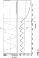
- FIGS. 3 and 4 graphs are shown illustrating a detection time at which the threshold condition (i.e., the detected rectified peak AC input voltage is less than the threshold voltage) is satisfied following an electrical decoupling of the power source 38 and the generator power supply unit 36.
- the top graph illustrates a maximum peak AC input voltage 78 of approximately 264 V rms and the bottom graph illustrates a corresponding detected rectified peak AC input voltage 80 and voltage threshold 82.
- the top graph illustrates a minimum peak AC input voltage 84 of approximately 177 V rms and the bottom graph illustrates a corresponding detected rectified peak AC input voltage 86 and voltage threshold 88.
- the maximum and minimum peak AC input voltages are provided as non-limiting examples and may correspond to other values, if desired.
- the power source 38 is decoupled from the generator power supply unit 36 at time T 1 , thereby ceasing the supply of the maximum and minimum peak AC input voltages 78, 84, respectively.
- the threshold condition is satisfied, thereby prompting the detection circuit 54 to transmit the switch-off signal 76 to the second converter 48 in order to trigger the discharge of the second energy reserve 52.
- the detection time i.e., the time between T 1 and T 2 , at which the threshold condition is satisfied is the same regardless of the input voltage supplied by the power source 38. Accordingly, by extension, the time necessary to discharge the second energy reserve 52 is independent of the input voltage (i.e., the voltage associated with the input power supplied by the power source 38) and the detected input voltage (i.e., the voltage detected on the main line).
- a flow diagram is shown illustrating a method 90 of operating a microwave oven during a door opening event.
- the method 90 may be implemented using the microwave oven 10 and associated components described previously with reference to FIGS. 1-4 .
- the method 90 includes, at step 94, interrupting a power input to the generator power supply unit 36, as set forth at step 94.
- this may be achieved by electrically decoupling the power source 38 from the generator power supply unit 36 via the interruption circuit 37 when the door 16 is moved to an open state.
- the detection circuit 54 is operated to detect an input voltage at step 96.
- the detected voltage may correspond to a detected rectified peak AC input voltage. If the detected input voltage satisfies a threshold condition (decision block 98), the detection circuit 54 disables the second converter 48 at step 100 via the switch-off signal 76. Otherwise, the detection circuit 54 continues to detect the input voltage until the threshold condition is satisfied. As described herein, disabling the second converter 48 triggers the second energy reserve 52 to discharge.
- the detection circuit 54 bypassing the first energy reserve 50, the time necessary to discharge the second energy reserve 52 is free of influence from the first energy reserve 50 and is independent of the detected input voltage, thus minimizing the exposure to microwave leakage.
- the second converter 48 may remain disabled until the door 16 is returned to a closed state, at which point the switch-off signal is deactivated, as set forth at step 102.
- the term "coupled” in all of its forms, couple, coupling, coupled, etc. generally means the joining of two components (electrical or mechanical) directly or indirectly to one another. Such joining may be stationary in nature or movable in nature. Such joining may be achieved with the two components (electrical or mechanical) and any additional intermediate members being integrally formed as a single unitary body with one another or with the two components. Such joining may be permanent in nature or may be removable or releasable in nature unless otherwise stated.
- elements shown as integrally formed may be constructed of multiple parts or elements shown as multiple parts may be integrally formed, the operation of the interfaces may be reversed or otherwise varied, the length or width of the structures and/or members or connector or other elements of the system may be varied, the nature or number of adjustment positions provided between the elements may be varied.
- the elements and/or assemblies of the system may be constructed from any of a wide variety of materials that provide sufficient strength or durability, in any of a wide variety of colors, textures, and combinations. Accordingly, all such modifications are intended to be included within the scope of the present innovations. Other substitutions, modifications, changes, and omissions may be made in the design, operating conditions, and arrangement of the desired and other exemplary embodiments.
Landscapes
- Physics & Mathematics (AREA)
- Electromagnetism (AREA)
- Engineering & Computer Science (AREA)
- Power Engineering (AREA)
- Electric Ovens (AREA)
- Constitution Of High-Frequency Heating (AREA)
- Dc-Dc Converters (AREA)
Claims (13)
- Mikrowellenherd (10), umfassend:eine Tür (16), die zwischen einem offenen Zustand und einem geschlossenen Zustand beweglich ist;einen Mikrowellengenerator zum Erzeugen von Mikrowellen; undeine Generatorstromversorgungseinheit (36), die von stromaufwärts nach stromabwärts der Reihe nach die folgenden Komponenten umfasst:einen ersten Wandler (46) zur Umwandlung einer Eingangsleistung in eine Ausgangsleistung;eine erste Energiereserve (50), die elektrisch mit dem ersten Wandler (46) gekoppelt ist, um die Ausgangsleistung zu empfangen;einen zweiten Wandler (48), der elektrisch mit der ersten Energiereserve (50) gekoppelt ist, um die Ausgangsleistung in eine Niederspannungs-Ausgangsleistung umzuwandeln; undeine zweite Energiereserve (52), die elektrisch mit dem zweiten Wandler (48) gekoppelt ist, um die Niederspannungs-Ausgangsleistung zu empfangen und die Niederspannungs-Ausgangsleistung an den Mikrowellengenerator zu liefern;gekennzeichnet durcheine Erfassungsschaltung (54), die konfiguriert ist, um eine Eingangsspannung zu erfassen und den zweiten Wandler (48) basierend darauf, dass die Tür (16) sich in dem offenen Zustand befindet, zu sperren, wobei das Sperren des zweiten Wandlers (48) das Entladen der zweiten Energiereserve (52) auslöst, und wobei die zum Entladen der zweiten Energiereserve (52) erforderliche Zeit von der ersten Energiereserve (50) unbeeinflusst ist.
- Mikrowellenherd (10) nach Anspruch 1, der ferner eine Unterbrechungsschaltung (37) zum elektrischen Entkoppeln der Generatorstromversorgungseinheit (36) von einer Stromquelle (38) umfasst, die konfiguriert ist, um die Eingangsleistung zu liefern, und wobei die Unterbrechungsschaltung (37) die Generatorstromversorgungseinheit (36) von der Stromquelle (38) elektrisch entkoppelt, wenn die Tür (16) im offenen Zustand ist.
- Mikrowellenherd (10) nach Anspruch 1 oder 2, bei dem die Erfassungsschaltung (54) einen Komparator (74) zum Vergleichen der erfassten Eingangsspannung mit einer Schwellenspannung umfasst, die proportional zur erfassten Eingangsspannung ist.
- Mikrowellenherd (10) nach Anspruch 3, wobei die Erfassungsschaltung (54) ein Abschaltsignal zum Sperren des zweiten Wandlers (48) sendet, wenn die erfasste Eingangsspannung kleiner als die Schwellenspannung ist.
- Mikrowellenherd (10) nach Anspruch 4, bei dem die Schwellenspannung auf einem Wert größer als Null gehalten ist.
- Mikrowellenherd (10) nach einem der Ansprüche 1 - 5, bei dem die Eingangsleistung eine Wechselstrom-Eingangsleistung umfasst, die Ausgangsleistung eine Gleichstrom-Eingangsleistung umfasst, die Niederspannungs-Ausgangsleistung eine Niederspannungs-Gleichstrom-Ausgangsleistung umfasst, und die Eingangsspannung eine gleichgerichtete Spitzen-Wechselstrom-Eingangsspannung umfasst.
- Mikrowellenherd (10) nach einem der Ansprüche 1 - 6, bei dem die Eingangsspannung stromaufwärts des ersten Wandlers erfasst wird.
- Mikrowellenherd (10) nach einem der Ansprüche 1-7, bei dem die Erfassungsschaltung (54) Komponenten der Generatorstromversorgungseinheit (36) umgeht, die stromaufwärts des zweiten Wandlers (48) angeordnet sind, so dass die erste Energiereserve (50) geladen bleibt, während die Entladung der zweiten Energiereserve (52) im Gange ist.
- Mikrowellenherd (10) nach Anspruch 1, bei dem die zum Entladen der zweiten Energiereserve erforderliche Zeit unabhängig von der erfassten Eingangsspannung ist.
- Verfahren zum Betreiben eines Mikrowellenherds (10) während eines Öffnungsvorgangs der Tür (16), mit den Schritten:Unterbrechen einer Stromzufuhr zu einer Generatorstromversorgungseinheit (36), wenn sich die Tür (16) in einem offenen Zustand befindet, wobei die Generatorstromversorgungseinheit (36) einen ersten Wandler (46), eine erste Energiereserve (50), eine zweite Energiereserve (52), die stromabwärts von der ersten Energiereserve (50) angeordnet ist, und einen zweiten Wandler (48), der zwischen der ersten und der zweiten Energiereserve (58 und 52) angeordnet ist, umfasst;Erfassen einer Eingangsspannung;gekennzeichnet durchSperren des zweiten Wandlers (48), wenn die erfasste Eingangsspannung kleiner als eine Schwellenspannung ist, die proportional zu der erfassten Eingangsspannung ist, wobei das Sperren des zweiten Wandlers (48) die zweite Energiereserve (52) veranlasst, sich zu entladen, undwobei die zum Entladen der zweiten Energiereserve (52) benötigte Zeit von der ersten Energiereserve (56) unbeeinflusst und unabhängig von der erfassten Eingangsspannung ist.
- Verfahren nach Anspruch 10, bei dem die Eingangsspannung unter Verwendung einer Unterbrechungsschaltung (37) zur elektrischen Entkopplung der Generatorstromversorgungseinheit (36) von einer zur Bereitstellung der Eingangsspannung konfigurierten Stromquelle (38) unterbrochen wird, und bei dem die Unterbrechungsschaltung (37) die Generatorstromversorgungseinheit (36) von der Stromquelle (38) elektrisch entkoppelt, wenn sich die Tür (16) im offenen Zustand befindet.
- Verfahren nach einem der Ansprüche 10 und 11, bei dem die erste Energiereserve (50) geladen bleibt, während die Entladung der zweiten Energiereserve (52) im Gange ist.
- Verfahren nach einem der Ansprüche 10 -12, bei die dem Schwellenspannung auf einem Wert größer als Null gehalten wird.
Applications Claiming Priority (1)
| Application Number | Priority Date | Filing Date | Title |
|---|---|---|---|
| PCT/US2016/048040 WO2018038702A1 (en) | 2016-08-22 | 2016-08-22 | Microwave oven having generator power supply |
Publications (3)
| Publication Number | Publication Date |
|---|---|
| EP3501239A1 EP3501239A1 (de) | 2019-06-26 |
| EP3501239A4 EP3501239A4 (de) | 2020-04-01 |
| EP3501239B1 true EP3501239B1 (de) | 2021-05-05 |
Family
ID=61246113
Family Applications (1)
| Application Number | Title | Priority Date | Filing Date |
|---|---|---|---|
| EP16914336.9A Active EP3501239B1 (de) | 2016-08-22 | 2016-08-22 | Mikrowellenofen mit generatorstromversorgung |
Country Status (5)
| Country | Link |
|---|---|
| US (2) | US11792897B2 (de) |
| EP (1) | EP3501239B1 (de) |
| JP (1) | JP6818125B2 (de) |
| CN (1) | CN109565912B (de) |
| WO (1) | WO2018038702A1 (de) |
Families Citing this family (1)
| Publication number | Priority date | Publication date | Assignee | Title |
|---|---|---|---|---|
| KR102726970B1 (ko) * | 2023-01-17 | 2024-11-07 | 오석주 | 충전식 배터리 일체형 인덕션 레인지 |
Family Cites Families (28)
| Publication number | Priority date | Publication date | Assignee | Title |
|---|---|---|---|---|
| JPS56147394A (en) * | 1980-04-17 | 1981-11-16 | Sharp Kk | N tube electronic range |
| JPS5743135A (en) * | 1980-08-29 | 1982-03-11 | Matsushita Electric Ind Co Ltd | High frequency heating device |
| US4648015A (en) | 1984-10-04 | 1987-03-03 | Motorola, Inc. | Filter capacitor discharge circuit for a DC-DC converter |
| JPS61259488A (ja) * | 1985-05-14 | 1986-11-17 | 松下電器産業株式会社 | 高周波加熱装置 |
| EP0280100B1 (de) * | 1987-02-10 | 1995-05-10 | Matsushita Electric Industrial Co., Ltd. | Hochfrequenz-Heizapparat |
| US4904837A (en) * | 1988-10-18 | 1990-02-27 | Low Douglas W | Powered microwave oven |
| US5347109A (en) * | 1990-07-25 | 1994-09-13 | Matsushita Electric Industrial Co., Ltd. | High-frequency heating apparatus mounted on a motor vehicle |
| KR940007232B1 (ko) * | 1991-12-31 | 1994-08-10 | 대우전자 주식회사 | 전자렌지의 도어 개폐장치 |
| RU2122338C1 (ru) * | 1997-04-08 | 1998-11-27 | Георгий Галиуллович Валеев | Устройство для приготовления пищи |
| JP3446654B2 (ja) | 1999-04-02 | 2003-09-16 | 株式会社村田製作所 | スイッチング電源装置 |
| KR100399135B1 (ko) * | 2000-07-27 | 2003-09-26 | 삼성전자주식회사 | 전자렌지 및 그 제어방법 |
| GB2367196B (en) | 2000-07-27 | 2002-09-25 | Samsung Electronics Co Ltd | Microwave oven having a switching power supply |
| KR100399134B1 (ko) * | 2000-07-27 | 2003-09-26 | 삼성전자주식회사 | 전자렌지 |
| US6781452B2 (en) | 2001-08-29 | 2004-08-24 | Tropian, Inc. | Power supply processing for power amplifiers |
| US7091777B2 (en) | 2002-09-30 | 2006-08-15 | Lucent Technologies Inc. | Controller for an RF power amplifier |
| EP1919260B1 (de) | 2005-08-26 | 2013-06-19 | Panasonic Corporation | Elektrisches gerät und heiz-kochgerät |
| JP4958440B2 (ja) | 2006-01-12 | 2012-06-20 | パナソニック株式会社 | 高周波加熱装置 |
| JP2007278635A (ja) * | 2006-04-10 | 2007-10-25 | Matsushita Electric Ind Co Ltd | 加熱調理器 |
| JP2011146143A (ja) | 2010-01-12 | 2011-07-28 | Panasonic Corp | マイクロ波処理装置 |
| JP5973322B2 (ja) * | 2012-10-31 | 2016-08-23 | 東芝シュネデール・インバータ株式会社 | インバータ装置の蓄積電力放電回路 |
| EP3000283B2 (de) | 2013-05-21 | 2021-12-01 | Goji Limited | Kalibrierung eines hf-verarbeitungssystems |
| CN103542436B (zh) * | 2013-10-29 | 2016-01-13 | 惠而浦(中国)股份有限公司 | 一种零微波泄漏的微波炉及其实现方法 |
| EP3087806B1 (de) | 2013-12-23 | 2021-06-09 | Whirlpool Corporation | Verfahren zur steuerung einer multifeed-funkfrequenzvorrichtung |
| JP6368371B2 (ja) * | 2013-12-23 | 2018-08-01 | ワールプール コーポレイション | 無線周波数発生器用の遮断回路 |
| WO2015099651A1 (en) | 2013-12-23 | 2015-07-02 | Whirlpool Corporation | Method of calibrating a multifeed radio frequency device |
| KR101759159B1 (ko) * | 2015-01-27 | 2017-07-18 | 엘지전자 주식회사 | 전력변환장치, 및 이를 구비하는 조리기기 |
| WO2016144872A1 (en) | 2015-03-06 | 2016-09-15 | Whirlpool Corporation | Method of calibrating a high power amplifier for a radio frequency power measurement system |
| CN105042649A (zh) * | 2015-07-08 | 2015-11-11 | 广东美的厨房电器制造有限公司 | 微波烹饪器具 |
-
2016
- 2016-08-22 EP EP16914336.9A patent/EP3501239B1/de active Active
- 2016-08-22 JP JP2019506704A patent/JP6818125B2/ja active Active
- 2016-08-22 US US16/307,232 patent/US11792897B2/en active Active
- 2016-08-22 WO PCT/US2016/048040 patent/WO2018038702A1/en not_active Ceased
- 2016-08-22 CN CN201680088454.6A patent/CN109565912B/zh active Active
-
2023
- 2023-09-06 US US18/461,613 patent/US12167524B2/en active Active
Also Published As
| Publication number | Publication date |
|---|---|
| EP3501239A4 (de) | 2020-04-01 |
| CN109565912A (zh) | 2019-04-02 |
| EP3501239A1 (de) | 2019-06-26 |
| US11792897B2 (en) | 2023-10-17 |
| US20190223262A1 (en) | 2019-07-18 |
| CN109565912B (zh) | 2021-10-29 |
| JP2019532241A (ja) | 2019-11-07 |
| US12167524B2 (en) | 2024-12-10 |
| JP6818125B2 (ja) | 2021-01-20 |
| WO2018038702A1 (en) | 2018-03-01 |
| US20230422363A1 (en) | 2023-12-28 |
Similar Documents
| Publication | Publication Date | Title |
|---|---|---|
| EP3120665B1 (de) | Röhrenlose mikrowellenvorrichtung | |
| US12302482B2 (en) | Interrupting circuit for a radio frequency generator | |
| US10050471B2 (en) | Inductive rotary joint with multimode inverter | |
| EP3563627B1 (de) | Preiswertes festkörper-hochfrequenzgenerierungssystem für elektromagnetisches kochen | |
| US9013346B2 (en) | Radar system comprising a switching mode power converter | |
| JP2012532580A (ja) | 調理器具用デジタル制御電源コンバータ | |
| US12167524B2 (en) | Microwave oven having generator power supply | |
| CN105276640A (zh) | 用于微波炉的控制方法和微波炉 | |
| KR20190096710A (ko) | 전원 공급 모듈 및 이를 포함하는 전자레인지 | |
| US20220183120A1 (en) | Microwave Oven | |
| KR102378759B1 (ko) | 전자 조리 기기 | |
| KR20200045796A (ko) | 안정성이 강화된 전자 조리 기기 | |
| KR920006212Y1 (ko) | 고주파 가열장치 | |
| KR101731389B1 (ko) | 마이크로웨이브를 이용한 조리기기 | |
| KR20210060266A (ko) | 인버터 전자레인지 | |
| JPH0910101A (ja) | マグネトロン応用加熱調理器 |
Legal Events
| Date | Code | Title | Description |
|---|---|---|---|
| STAA | Information on the status of an ep patent application or granted ep patent |
Free format text: STATUS: THE INTERNATIONAL PUBLICATION HAS BEEN MADE |
|
| PUAI | Public reference made under article 153(3) epc to a published international application that has entered the european phase |
Free format text: ORIGINAL CODE: 0009012 |
|
| STAA | Information on the status of an ep patent application or granted ep patent |
Free format text: STATUS: REQUEST FOR EXAMINATION WAS MADE |
|
| 17P | Request for examination filed |
Effective date: 20181204 |
|
| AK | Designated contracting states |
Kind code of ref document: A1 Designated state(s): AL AT BE BG CH CY CZ DE DK EE ES FI FR GB GR HR HU IE IS IT LI LT LU LV MC MK MT NL NO PL PT RO RS SE SI SK SM TR |
|
| AX | Request for extension of the european patent |
Extension state: BA ME |
|
| DAV | Request for validation of the european patent (deleted) | ||
| DAX | Request for extension of the european patent (deleted) | ||
| A4 | Supplementary search report drawn up and despatched |
Effective date: 20200227 |
|
| RIC1 | Information provided on ipc code assigned before grant |
Ipc: H05B 6/64 20060101AFI20200222BHEP Ipc: F24C 7/02 20060101ALI20200222BHEP |
|
| REG | Reference to a national code |
Ref country code: DE Ref legal event code: R079 Ref document number: 602016057641 Country of ref document: DE Free format text: PREVIOUS MAIN CLASS: H05B0006640000 Ipc: H05B0006660000 |
|
| GRAP | Despatch of communication of intention to grant a patent |
Free format text: ORIGINAL CODE: EPIDOSNIGR1 |
|
| STAA | Information on the status of an ep patent application or granted ep patent |
Free format text: STATUS: GRANT OF PATENT IS INTENDED |
|
| RIC1 | Information provided on ipc code assigned before grant |
Ipc: H05B 6/66 20060101AFI20201007BHEP Ipc: H05B 6/64 20060101ALI20201007BHEP Ipc: F24C 7/02 20060101ALI20201007BHEP |
|
| INTG | Intention to grant announced |
Effective date: 20201102 |
|
| GRAS | Grant fee paid |
Free format text: ORIGINAL CODE: EPIDOSNIGR3 |
|
| GRAA | (expected) grant |
Free format text: ORIGINAL CODE: 0009210 |
|
| STAA | Information on the status of an ep patent application or granted ep patent |
Free format text: STATUS: THE PATENT HAS BEEN GRANTED |
|
| RAP3 | Party data changed (applicant data changed or rights of an application transferred) |
Owner name: WHIRLPOOL CORPORATION Owner name: PANASONIC CORPORATION |
|
| AK | Designated contracting states |
Kind code of ref document: B1 Designated state(s): AL AT BE BG CH CY CZ DE DK EE ES FI FR GB GR HR HU IE IS IT LI LT LU LV MC MK MT NL NO PL PT RO RS SE SI SK SM TR |
|
| REG | Reference to a national code |
Ref country code: GB Ref legal event code: FG4D |
|
| REG | Reference to a national code |
Ref country code: CH Ref legal event code: EP |
|
| REG | Reference to a national code |
Ref country code: AT Ref legal event code: REF Ref document number: 1391501 Country of ref document: AT Kind code of ref document: T Effective date: 20210515 |
|
| REG | Reference to a national code |
Ref country code: IE Ref legal event code: FG4D |
|
| REG | Reference to a national code |
Ref country code: DE Ref legal event code: R096 Ref document number: 602016057641 Country of ref document: DE |
|
| REG | Reference to a national code |
Ref country code: LT Ref legal event code: MG9D |
|
| REG | Reference to a national code |
Ref country code: AT Ref legal event code: MK05 Ref document number: 1391501 Country of ref document: AT Kind code of ref document: T Effective date: 20210505 |
|
| PG25 | Lapsed in a contracting state [announced via postgrant information from national office to epo] |
Ref country code: HR Free format text: LAPSE BECAUSE OF FAILURE TO SUBMIT A TRANSLATION OF THE DESCRIPTION OR TO PAY THE FEE WITHIN THE PRESCRIBED TIME-LIMIT Effective date: 20210505 Ref country code: BG Free format text: LAPSE BECAUSE OF FAILURE TO SUBMIT A TRANSLATION OF THE DESCRIPTION OR TO PAY THE FEE WITHIN THE PRESCRIBED TIME-LIMIT Effective date: 20210805 Ref country code: AT Free format text: LAPSE BECAUSE OF FAILURE TO SUBMIT A TRANSLATION OF THE DESCRIPTION OR TO PAY THE FEE WITHIN THE PRESCRIBED TIME-LIMIT Effective date: 20210505 Ref country code: LT Free format text: LAPSE BECAUSE OF FAILURE TO SUBMIT A TRANSLATION OF THE DESCRIPTION OR TO PAY THE FEE WITHIN THE PRESCRIBED TIME-LIMIT Effective date: 20210505 Ref country code: FI Free format text: LAPSE BECAUSE OF FAILURE TO SUBMIT A TRANSLATION OF THE DESCRIPTION OR TO PAY THE FEE WITHIN THE PRESCRIBED TIME-LIMIT Effective date: 20210505 |
|
| PG25 | Lapsed in a contracting state [announced via postgrant information from national office to epo] |
Ref country code: LV Free format text: LAPSE BECAUSE OF FAILURE TO SUBMIT A TRANSLATION OF THE DESCRIPTION OR TO PAY THE FEE WITHIN THE PRESCRIBED TIME-LIMIT Effective date: 20210505 Ref country code: GR Free format text: LAPSE BECAUSE OF FAILURE TO SUBMIT A TRANSLATION OF THE DESCRIPTION OR TO PAY THE FEE WITHIN THE PRESCRIBED TIME-LIMIT Effective date: 20210806 Ref country code: IS Free format text: LAPSE BECAUSE OF FAILURE TO SUBMIT A TRANSLATION OF THE DESCRIPTION OR TO PAY THE FEE WITHIN THE PRESCRIBED TIME-LIMIT Effective date: 20210905 Ref country code: PT Free format text: LAPSE BECAUSE OF FAILURE TO SUBMIT A TRANSLATION OF THE DESCRIPTION OR TO PAY THE FEE WITHIN THE PRESCRIBED TIME-LIMIT Effective date: 20210906 Ref country code: PL Free format text: LAPSE BECAUSE OF FAILURE TO SUBMIT A TRANSLATION OF THE DESCRIPTION OR TO PAY THE FEE WITHIN THE PRESCRIBED TIME-LIMIT Effective date: 20210505 Ref country code: NO Free format text: LAPSE BECAUSE OF FAILURE TO SUBMIT A TRANSLATION OF THE DESCRIPTION OR TO PAY THE FEE WITHIN THE PRESCRIBED TIME-LIMIT Effective date: 20210805 Ref country code: RS Free format text: LAPSE BECAUSE OF FAILURE TO SUBMIT A TRANSLATION OF THE DESCRIPTION OR TO PAY THE FEE WITHIN THE PRESCRIBED TIME-LIMIT Effective date: 20210505 Ref country code: SE Free format text: LAPSE BECAUSE OF FAILURE TO SUBMIT A TRANSLATION OF THE DESCRIPTION OR TO PAY THE FEE WITHIN THE PRESCRIBED TIME-LIMIT Effective date: 20210505 |
|
| REG | Reference to a national code |
Ref country code: NL Ref legal event code: MP Effective date: 20210505 |
|
| PG25 | Lapsed in a contracting state [announced via postgrant information from national office to epo] |
Ref country code: NL Free format text: LAPSE BECAUSE OF FAILURE TO SUBMIT A TRANSLATION OF THE DESCRIPTION OR TO PAY THE FEE WITHIN THE PRESCRIBED TIME-LIMIT Effective date: 20210505 |
|
| PG25 | Lapsed in a contracting state [announced via postgrant information from national office to epo] |
Ref country code: DK Free format text: LAPSE BECAUSE OF FAILURE TO SUBMIT A TRANSLATION OF THE DESCRIPTION OR TO PAY THE FEE WITHIN THE PRESCRIBED TIME-LIMIT Effective date: 20210505 Ref country code: EE Free format text: LAPSE BECAUSE OF FAILURE TO SUBMIT A TRANSLATION OF THE DESCRIPTION OR TO PAY THE FEE WITHIN THE PRESCRIBED TIME-LIMIT Effective date: 20210505 Ref country code: CZ Free format text: LAPSE BECAUSE OF FAILURE TO SUBMIT A TRANSLATION OF THE DESCRIPTION OR TO PAY THE FEE WITHIN THE PRESCRIBED TIME-LIMIT Effective date: 20210505 Ref country code: ES Free format text: LAPSE BECAUSE OF FAILURE TO SUBMIT A TRANSLATION OF THE DESCRIPTION OR TO PAY THE FEE WITHIN THE PRESCRIBED TIME-LIMIT Effective date: 20210505 Ref country code: RO Free format text: LAPSE BECAUSE OF FAILURE TO SUBMIT A TRANSLATION OF THE DESCRIPTION OR TO PAY THE FEE WITHIN THE PRESCRIBED TIME-LIMIT Effective date: 20210505 Ref country code: SK Free format text: LAPSE BECAUSE OF FAILURE TO SUBMIT A TRANSLATION OF THE DESCRIPTION OR TO PAY THE FEE WITHIN THE PRESCRIBED TIME-LIMIT Effective date: 20210505 Ref country code: SM Free format text: LAPSE BECAUSE OF FAILURE TO SUBMIT A TRANSLATION OF THE DESCRIPTION OR TO PAY THE FEE WITHIN THE PRESCRIBED TIME-LIMIT Effective date: 20210505 |
|
| REG | Reference to a national code |
Ref country code: DE Ref legal event code: R097 Ref document number: 602016057641 Country of ref document: DE |
|
| PLBE | No opposition filed within time limit |
Free format text: ORIGINAL CODE: 0009261 |
|
| STAA | Information on the status of an ep patent application or granted ep patent |
Free format text: STATUS: NO OPPOSITION FILED WITHIN TIME LIMIT |
|
| REG | Reference to a national code |
Ref country code: CH Ref legal event code: PL |
|
| PG25 | Lapsed in a contracting state [announced via postgrant information from national office to epo] |
Ref country code: MC Free format text: LAPSE BECAUSE OF FAILURE TO SUBMIT A TRANSLATION OF THE DESCRIPTION OR TO PAY THE FEE WITHIN THE PRESCRIBED TIME-LIMIT Effective date: 20210505 |
|
| 26N | No opposition filed |
Effective date: 20220208 |
|
| REG | Reference to a national code |
Ref country code: BE Ref legal event code: MM Effective date: 20210831 |
|
| PG25 | Lapsed in a contracting state [announced via postgrant information from national office to epo] |
Ref country code: LI Free format text: LAPSE BECAUSE OF NON-PAYMENT OF DUE FEES Effective date: 20210831 Ref country code: CH Free format text: LAPSE BECAUSE OF NON-PAYMENT OF DUE FEES Effective date: 20210831 |
|
| PG25 | Lapsed in a contracting state [announced via postgrant information from national office to epo] |
Ref country code: IS Free format text: LAPSE BECAUSE OF FAILURE TO SUBMIT A TRANSLATION OF THE DESCRIPTION OR TO PAY THE FEE WITHIN THE PRESCRIBED TIME-LIMIT Effective date: 20210905 Ref country code: LU Free format text: LAPSE BECAUSE OF NON-PAYMENT OF DUE FEES Effective date: 20210822 Ref country code: AL Free format text: LAPSE BECAUSE OF FAILURE TO SUBMIT A TRANSLATION OF THE DESCRIPTION OR TO PAY THE FEE WITHIN THE PRESCRIBED TIME-LIMIT Effective date: 20210505 |
|
| PG25 | Lapsed in a contracting state [announced via postgrant information from national office to epo] |
Ref country code: IE Free format text: LAPSE BECAUSE OF NON-PAYMENT OF DUE FEES Effective date: 20210822 Ref country code: BE Free format text: LAPSE BECAUSE OF NON-PAYMENT OF DUE FEES Effective date: 20210831 |
|
| P01 | Opt-out of the competence of the unified patent court (upc) registered |
Effective date: 20230522 |
|
| PG25 | Lapsed in a contracting state [announced via postgrant information from national office to epo] |
Ref country code: CY Free format text: LAPSE BECAUSE OF FAILURE TO SUBMIT A TRANSLATION OF THE DESCRIPTION OR TO PAY THE FEE WITHIN THE PRESCRIBED TIME-LIMIT Effective date: 20210505 |
|
| PG25 | Lapsed in a contracting state [announced via postgrant information from national office to epo] |
Ref country code: HU Free format text: LAPSE BECAUSE OF FAILURE TO SUBMIT A TRANSLATION OF THE DESCRIPTION OR TO PAY THE FEE WITHIN THE PRESCRIBED TIME-LIMIT; INVALID AB INITIO Effective date: 20160822 |
|
| PG25 | Lapsed in a contracting state [announced via postgrant information from national office to epo] |
Ref country code: MK Free format text: LAPSE BECAUSE OF FAILURE TO SUBMIT A TRANSLATION OF THE DESCRIPTION OR TO PAY THE FEE WITHIN THE PRESCRIBED TIME-LIMIT Effective date: 20210505 |
|
| PG25 | Lapsed in a contracting state [announced via postgrant information from national office to epo] |
Ref country code: TR Free format text: LAPSE BECAUSE OF FAILURE TO SUBMIT A TRANSLATION OF THE DESCRIPTION OR TO PAY THE FEE WITHIN THE PRESCRIBED TIME-LIMIT Effective date: 20210505 |
|
| PG25 | Lapsed in a contracting state [announced via postgrant information from national office to epo] |
Ref country code: MT Free format text: LAPSE BECAUSE OF FAILURE TO SUBMIT A TRANSLATION OF THE DESCRIPTION OR TO PAY THE FEE WITHIN THE PRESCRIBED TIME-LIMIT Effective date: 20210505 |
|
| PGFP | Annual fee paid to national office [announced via postgrant information from national office to epo] |
Ref country code: DE Payment date: 20250709 Year of fee payment: 10 |
|
| PGFP | Annual fee paid to national office [announced via postgrant information from national office to epo] |
Ref country code: IT Payment date: 20250710 Year of fee payment: 10 |
|
| PGFP | Annual fee paid to national office [announced via postgrant information from national office to epo] |
Ref country code: GB Payment date: 20250710 Year of fee payment: 10 |
|
| PGFP | Annual fee paid to national office [announced via postgrant information from national office to epo] |
Ref country code: FR Payment date: 20250825 Year of fee payment: 10 |