EP3500734B1 - Gemäss einem rankine-kreislauf funktionierender geschlossener schaltkreis mit einer notstoppvorrichtung für den schaltkreis und verfahren mit solch einem schaltkreis - Google Patents
Gemäss einem rankine-kreislauf funktionierender geschlossener schaltkreis mit einer notstoppvorrichtung für den schaltkreis und verfahren mit solch einem schaltkreis Download PDFInfo
- Publication number
- EP3500734B1 EP3500734B1 EP17736963.4A EP17736963A EP3500734B1 EP 3500734 B1 EP3500734 B1 EP 3500734B1 EP 17736963 A EP17736963 A EP 17736963A EP 3500734 B1 EP3500734 B1 EP 3500734B1
- Authority
- EP
- European Patent Office
- Prior art keywords
- circuit
- fluid
- heat exchanger
- pump
- working fluid
- Prior art date
- Legal status (The legal status is an assumption and is not a legal conclusion. Google has not performed a legal analysis and makes no representation as to the accuracy of the status listed.)
- Active
Links
- 238000000034 method Methods 0.000 title claims description 10
- 239000012530 fluid Substances 0.000 claims description 94
- 239000007788 liquid Substances 0.000 claims description 24
- 238000001816 cooling Methods 0.000 claims description 12
- 238000011144 upstream manufacturing Methods 0.000 claims description 10
- 230000006835 compression Effects 0.000 claims description 5
- 238000007906 compression Methods 0.000 claims description 5
- 238000002485 combustion reaction Methods 0.000 description 6
- 238000004519 manufacturing process Methods 0.000 description 6
- QGZKDVFQNNGYKY-UHFFFAOYSA-N Ammonia Chemical compound N QGZKDVFQNNGYKY-UHFFFAOYSA-N 0.000 description 4
- CURLTUGMZLYLDI-UHFFFAOYSA-N Carbon dioxide Chemical compound O=C=O CURLTUGMZLYLDI-UHFFFAOYSA-N 0.000 description 4
- LFQSCWFLJHTTHZ-UHFFFAOYSA-N Ethanol Chemical compound CCO LFQSCWFLJHTTHZ-UHFFFAOYSA-N 0.000 description 4
- 239000007789 gas Substances 0.000 description 4
- 230000008016 vaporization Effects 0.000 description 3
- 230000004913 activation Effects 0.000 description 2
- 239000003570 air Substances 0.000 description 2
- 229910021529 ammonia Inorganic materials 0.000 description 2
- 239000001273 butane Substances 0.000 description 2
- 239000001569 carbon dioxide Substances 0.000 description 2
- 229910002092 carbon dioxide Inorganic materials 0.000 description 2
- 238000009833 condensation Methods 0.000 description 2
- 230000005494 condensation Effects 0.000 description 2
- 239000012809 cooling fluid Substances 0.000 description 2
- 239000000110 cooling liquid Substances 0.000 description 2
- 239000000498 cooling water Substances 0.000 description 2
- 238000001704 evaporation Methods 0.000 description 2
- 230000008020 evaporation Effects 0.000 description 2
- 239000000463 material Substances 0.000 description 2
- 239000000203 mixture Substances 0.000 description 2
- IJDNQMDRQITEOD-UHFFFAOYSA-N n-butane Chemical compound CCCC IJDNQMDRQITEOD-UHFFFAOYSA-N 0.000 description 2
- OFBQJSOFQDEBGM-UHFFFAOYSA-N n-pentane Natural products CCCCC OFBQJSOFQDEBGM-UHFFFAOYSA-N 0.000 description 2
- 238000009834 vaporization Methods 0.000 description 2
- XLYOFNOQVPJJNP-UHFFFAOYSA-N water Substances O XLYOFNOQVPJJNP-UHFFFAOYSA-N 0.000 description 2
- 229910001868 water Inorganic materials 0.000 description 2
- 230000009471 action Effects 0.000 description 1
- 239000012080 ambient air Substances 0.000 description 1
- 238000001514 detection method Methods 0.000 description 1
- 230000000694 effects Effects 0.000 description 1
- 239000013529 heat transfer fluid Substances 0.000 description 1
- 238000010438 heat treatment Methods 0.000 description 1
- -1 hydrofluorocarbons Chemical compound 0.000 description 1
- 230000004941 influx Effects 0.000 description 1
- 238000009434 installation Methods 0.000 description 1
- 230000007257 malfunction Effects 0.000 description 1
- 238000013021 overheating Methods 0.000 description 1
- 238000010248 power generation Methods 0.000 description 1
Images
Classifications
-
- F—MECHANICAL ENGINEERING; LIGHTING; HEATING; WEAPONS; BLASTING
- F01—MACHINES OR ENGINES IN GENERAL; ENGINE PLANTS IN GENERAL; STEAM ENGINES
- F01K—STEAM ENGINE PLANTS; STEAM ACCUMULATORS; ENGINE PLANTS NOT OTHERWISE PROVIDED FOR; ENGINES USING SPECIAL WORKING FLUIDS OR CYCLES
- F01K13/00—General layout or general methods of operation of complete plants
- F01K13/02—Controlling, e.g. stopping or starting
- F01K13/025—Cooling the interior by injection during idling or stand-by
-
- F—MECHANICAL ENGINEERING; LIGHTING; HEATING; WEAPONS; BLASTING
- F01—MACHINES OR ENGINES IN GENERAL; ENGINE PLANTS IN GENERAL; STEAM ENGINES
- F01D—NON-POSITIVE DISPLACEMENT MACHINES OR ENGINES, e.g. STEAM TURBINES
- F01D17/00—Regulating or controlling by varying flow
- F01D17/10—Final actuators
-
- F—MECHANICAL ENGINEERING; LIGHTING; HEATING; WEAPONS; BLASTING
- F01—MACHINES OR ENGINES IN GENERAL; ENGINE PLANTS IN GENERAL; STEAM ENGINES
- F01D—NON-POSITIVE DISPLACEMENT MACHINES OR ENGINES, e.g. STEAM TURBINES
- F01D21/00—Shutting-down of machines or engines, e.g. in emergency; Regulating, controlling, or safety means not otherwise provided for
-
- F—MECHANICAL ENGINEERING; LIGHTING; HEATING; WEAPONS; BLASTING
- F01—MACHINES OR ENGINES IN GENERAL; ENGINE PLANTS IN GENERAL; STEAM ENGINES
- F01D—NON-POSITIVE DISPLACEMENT MACHINES OR ENGINES, e.g. STEAM TURBINES
- F01D25/00—Component parts, details, or accessories, not provided for in, or of interest apart from, other groups
- F01D25/08—Cooling; Heating; Heat-insulation
-
- F—MECHANICAL ENGINEERING; LIGHTING; HEATING; WEAPONS; BLASTING
- F01—MACHINES OR ENGINES IN GENERAL; ENGINE PLANTS IN GENERAL; STEAM ENGINES
- F01K—STEAM ENGINE PLANTS; STEAM ACCUMULATORS; ENGINE PLANTS NOT OTHERWISE PROVIDED FOR; ENGINES USING SPECIAL WORKING FLUIDS OR CYCLES
- F01K13/00—General layout or general methods of operation of complete plants
-
- F—MECHANICAL ENGINEERING; LIGHTING; HEATING; WEAPONS; BLASTING
- F01—MACHINES OR ENGINES IN GENERAL; ENGINE PLANTS IN GENERAL; STEAM ENGINES
- F01K—STEAM ENGINE PLANTS; STEAM ACCUMULATORS; ENGINE PLANTS NOT OTHERWISE PROVIDED FOR; ENGINES USING SPECIAL WORKING FLUIDS OR CYCLES
- F01K23/00—Plants characterised by more than one engine delivering power external to the plant, the engines being driven by different fluids
- F01K23/02—Plants characterised by more than one engine delivering power external to the plant, the engines being driven by different fluids the engine cycles being thermally coupled
- F01K23/06—Plants characterised by more than one engine delivering power external to the plant, the engines being driven by different fluids the engine cycles being thermally coupled combustion heat from one cycle heating the fluid in another cycle
- F01K23/08—Plants characterised by more than one engine delivering power external to the plant, the engines being driven by different fluids the engine cycles being thermally coupled combustion heat from one cycle heating the fluid in another cycle with working fluid of one cycle heating the fluid in another cycle
-
- F—MECHANICAL ENGINEERING; LIGHTING; HEATING; WEAPONS; BLASTING
- F01—MACHINES OR ENGINES IN GENERAL; ENGINE PLANTS IN GENERAL; STEAM ENGINES
- F01K—STEAM ENGINE PLANTS; STEAM ACCUMULATORS; ENGINE PLANTS NOT OTHERWISE PROVIDED FOR; ENGINES USING SPECIAL WORKING FLUIDS OR CYCLES
- F01K9/00—Plants characterised by condensers arranged or modified to co-operate with the engines
- F01K9/003—Plants characterised by condensers arranged or modified to co-operate with the engines condenser cooling circuits
-
- F—MECHANICAL ENGINEERING; LIGHTING; HEATING; WEAPONS; BLASTING
- F05—INDEXING SCHEMES RELATING TO ENGINES OR PUMPS IN VARIOUS SUBCLASSES OF CLASSES F01-F04
- F05D—INDEXING SCHEME FOR ASPECTS RELATING TO NON-POSITIVE-DISPLACEMENT MACHINES OR ENGINES, GAS-TURBINES OR JET-PROPULSION PLANTS
- F05D2210/00—Working fluids
- F05D2210/10—Kind or type
-
- F—MECHANICAL ENGINEERING; LIGHTING; HEATING; WEAPONS; BLASTING
- F05—INDEXING SCHEMES RELATING TO ENGINES OR PUMPS IN VARIOUS SUBCLASSES OF CLASSES F01-F04
- F05D—INDEXING SCHEME FOR ASPECTS RELATING TO NON-POSITIVE-DISPLACEMENT MACHINES OR ENGINES, GAS-TURBINES OR JET-PROPULSION PLANTS
- F05D2220/00—Application
- F05D2220/30—Application in turbines
- F05D2220/31—Application in turbines in steam turbines
-
- F—MECHANICAL ENGINEERING; LIGHTING; HEATING; WEAPONS; BLASTING
- F22—STEAM GENERATION
- F22B—METHODS OF STEAM GENERATION; STEAM BOILERS
- F22B37/00—Component parts or details of steam boilers
- F22B37/02—Component parts or details of steam boilers applicable to more than one kind or type of steam boiler
- F22B37/48—Devices for removing water, salt, or sludge from boilers; Arrangements of cleaning apparatus in boilers; Combinations thereof with boilers
- F22B37/50—Devices for removing water, salt, or sludge from boilers; Arrangements of cleaning apparatus in boilers; Combinations thereof with boilers for draining or expelling water
Definitions
- the present invention relates to a closed circuit operating according to a Rankine cycle with a device for emergency shutdown of this circuit as well as to a method using a circuit with such a device.
- the Rankine cycle is a thermodynamic cycle by which heat from an external heat source is transferred to a closed circuit which contains a working fluid. During the cycle, the working fluid undergoes phase changes (liquid/vapor).
- This type of cycle generally breaks down into a step during which the working fluid used in liquid form is compressed isentropically, followed by a step where this compressed liquid fluid is heated and vaporized in contact with a heat source.
- This vapor is then expanded, during another stage, in an expansion machine, then, in a final stage, this expanded vapor is cooled and condensed in contact with a cold source.
- the circuit comprises at least one pump-compressor for circulating and compressing the fluid in liquid form, an evaporator which is swept by a hot fluid to carry out at least partial vaporization of the compressed fluid, an expansion machine to expand the steam, such as a turbine, which transforms the energy of this steam into another energy, such as mechanical or electrical energy, and a condenser by which the heat contained in the steam is given up to a cold source, generally outside air, or even a cooling water circuit, which sweeps this condenser, to transform this vapor into a fluid in liquid form.
- a pump-compressor for circulating and compressing the fluid in liquid form
- an evaporator which is swept by a hot fluid to carry out at least partial vaporization of the compressed fluid
- an expansion machine to expand the steam such as a turbine, which transforms the energy of this steam into another energy, such as mechanical or electrical energy
- a condenser by which the heat contained in the steam is given up to a cold source, generally outside air, or
- the fluid used is generally water but other types of fluid, for example organic fluids or mixtures of organic fluids, can also be used.
- the cycle is then called Organic Rankine Cycle or ORC (Organic Rankine Cycle).
- the working fluids can be butane, ethanol, hydrofluorocarbons, ammonia, carbon dioxide...
- the hot fluid to carry out the vaporization of the compressed fluid can come from various hot sources, such as a cooling liquid (from a combustion engine, from an industrial process, from a furnace, etc. .), hot gases resulting from combustion (smokes from an industrial process, from a boiler, exhaust gases from a combustion engine or turbine, etc.), from a flow of heat from solar thermal collectors, etc.
- a cooling liquid from a combustion engine, from an industrial process, from a furnace, etc. .
- hot gases resulting from combustion smoke from an industrial process, from a boiler, exhaust gases from a combustion engine or turbine, etc.
- solar thermal collectors etc.
- the Rankine cycle circuit thus makes it possible to improve the efficiency of the engine.
- the presence of working fluid in the liquid state in at least part of this evaporator or further in the circuit leads to the production of steam during several tens of seconds after the activation of the emergency stop.
- the second valve then allows the working fluid vapor present upstream of the expansion machine to be diverted directly downstream of this machine.
- the expansion machine being thus short-circuited, the circuit is no longer able to produce energy and the production of energy quickly stops.
- this second valve is located in a branch of the circuit where the working fluid is both under pressure, hot and in gaseous form. It must therefore be chosen accordingly with materials resistant to temperature and pressure and with a size, in particular at the level of its passage section, adapted to allow the flow of steam to pass in the event of its actuation.
- the present invention as defined in claim 1 proposes to remedy the above drawbacks by proposing a closed circuit with a device which makes it possible to avoid, in the event of an emergency shutdown of this circuit, the influx of fluid work vaporized at the entrance of the expansion machine.
- the invention relates to a closed circuit operating according to a Rankine cycle, said circuit comprising at least one circulation pump and compression with an inlet and an outlet for a working fluid in liquid form, a heat exchanger swept by a hot source for the evaporation of said fluid circulating between an inlet and an outlet of said heat exchanger, fluid expansion means in vapor form, a cooling exchanger swept by a cold source for the condensation of the working fluid circulating between an inlet and an outlet of said cooling exchanger, a working fluid reservoir, and working fluid circulation pipes to make circulating said fluid between the pump, the heat exchanger, the expansion means, the condenser and the tank, furthermore the circuit comprises a device for draining the fluid contained in the heat exchanger in the event of an emergency stop of said circuit, and the circuit comprises a non-return valve placed in the vicinity of the pump outlet and a filter.
- the drain device may comprise a drain pipe connected to two connection points of the circuit and carrying a valve means.
- the valve means can be a two-way valve placed on the conduit between the two connection points.
- the valve means can be a three-way valve placed on one of the connection points with the circuit.
- the valve means can be a solenoid valve
- connection points can be placed between the pump and the heat exchanger and the other of the connection points can be placed between the cooling exchanger and the pump.
- the circuit may include a device for short-circuiting the hot source passing through the heat exchanger.
- the invention as defined in claim 8 also relates to a method for controlling a closed circuit operating according to a Rankine cycle, said circuit comprising at least one circulation and compression pump with an inlet and an outlet for a fluid working in liquid form, a heat exchanger swept by a hot source for the evaporation of said fluid circulating between an inlet and an outlet of said heat exchanger, means for expanding the fluid in vapor form, a cooling exchanger swept by a cold source for condensing the working fluid circulating between an inlet and an outlet of said cooling exchanger, a working fluid reservoir, a non-return valve placed in the vicinity of the pump outlet and a filter, and circulation pipes for the working fluid for circulating said fluid between the pump, the heat exchanger, the expansion means, the condenser and the reservoir , in the event of an emergency shutdown of the circuit, the fluid contained in the heat exchanger is transferred to the part of the circuit between the upstream of the pump and the tank.
- the fluid contained in the heat exchanger can be transferred to the reservoir.
- the fluid contained in the heat exchanger can be transferred to the pipe connecting the upstream of the pump and the reservoir.
- the circulation of the working fluid in the drain pipe can be controlled by a valve means.
- Hot source circulation can be bypassed to bypass the heat exchanger
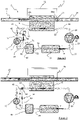
- the figures 1 and 2 illustrate an embodiment of a closed Rankine cycle circuit 10 which is advantageously of the ORC (Organic Rankine Cycle) type and which uses an organic working fluid or mixtures of organic fluids, such as butane, ethanol, hydrofluorocarbons...
- ORC Organic Rankine Cycle
- closed circuit can also work with a fluid such as ammonia, water, carbon dioxide...
- This circuit comprises a circulation and compression pump 12 for the working fluid, referred to as the circulation pump in the remainder of the description, with an inlet 14 for the working fluid in liquid form and an outlet 16 for this working fluid also in liquid form. liquid but compressed under high pressure.
- This pump is advantageously driven in rotation by any means; such as an electric motor (not shown).
- This circuit also comprises a heat exchanger 18, called an evaporator, through which the compressed working fluid passes between an inlet 20 of this liquid fluid and an outlet 22 through which the working fluid emerges from this evaporator in the form of compressed vapour.
- This evaporator is also traversed by a hot source 23, in liquid or gaseous form, transported by a pipe 24 between an inlet 25a and an outlet 25b so as to be able to transfer its heat to the working fluid.
- This hot source can, for example, come from the exhaust gases of an internal combustion engine, from the cooling fluid of an internal combustion engine, from the cooling fluid of an industrial furnace, or from the heat transfer fluid heated in installations. heat or by a burner.
- This circuit also includes an expansion machine 26 receiving through its inlet 28 the working fluid in the form of high pressure compressed vapour, this fluid emerging through the outlet 30 of this machine in the form of low pressure expanded vapour.
- this expansion machine is in the form of an expansion turbine, the shaft of the rotor of which is driven in rotation by the working fluid in the form of vapor by controlling in rotation a connecting shaft 32.
- this shaft makes it possible to transmit the energy recovered from the working fluid to any transformer device, such as for example an electric generator (not shown).
- the circuit further comprises a cooling exchanger 34, or condenser, with an inlet 36 for the expanded low-pressure steam and an outlet 38 for the low-pressure working fluid transformed into liquid form after it has passed through this condenser.
- a cooling exchanger 34 or condenser
- This condenser is swept by a cold source, usually a flow of ambient air or cooling water, so as to cool the expanded vapor so that it condenses and turns into a liquid.
- any other cold source of cooling such as another cooling liquid or cold air, can be used to ensure the condensation of the vapor.
- This circuit also comprises, between the condenser and the circulation pump, a closed tank 40 which makes it possible to keep the working fluid in the liquid state.
- the circuit comprises a non-return valve 42 placed near the outlet 16 of the pump 12 and a filter (not shown), such as a cartridge filter, to filter the working fluid leaving the reservoir before it is introduced into the pump.
- a filter such as a cartridge filter
- valve pipe 44 valve pipe 44
- valve line 46 valve line 46
- turbine line 48 turbine line 48
- this turbine with the condenser condenser line 50
- tank line 52 tank with the pump
- pump line 54 pump line 54
- This circuit further comprises a device 56 for emptying the fluid contained in the heat exchanger 18, which makes it possible, in the event of an emergency shutdown of the circuit, to transfer the pressurized liquid contained in this exchanger to the reservoir or to the part of the circuit located between this tank and the upstream of the pump.
- this drain device 56 comprises a drain pipe 58 which originates at a connection point 60 of the circuit upstream of the evaporator and downstream of the pump (considering the direction of circulation of the working fluid according to the arrows F) on the pipe or 46 where the fluid is in liquid form and ends at another connection point 62 of this circuit upstream of the pump and downstream of the condenser on one of the pipes 52 or 54 where the fluid is also in liquid form.
- this conduit originates at a point 60 of the circuit between the non-return valve 42 and the inlet 20 of the evaporator and ends at a point 62 of the circuit placed between the outlet of the tank 40 and inlet 14 of pump 12.
- valve means 64 makes it possible to control the circulation of the working fluid in liquid form which circulates in this conduit.
- This valve means is a two-way valve 66 in the case of the figure 1 and is located on conduit 58 at a distance from the two connection points.
- valve means 64 is a three-way valve 68 which is placed on the connection point 60 with the pipe 46.
- valves can be controlled by any known means, such as electric, pneumatic, hydraulic means, etc.
- these valves can also be solenoid valves, in particular solenoid valves.
- this drain pipe and the valve which controls its actuation are only subjected to a moderate temperature.
- the choice of materials for this valve is therefore less restrictive.
- the drain device 56 is provided to pass the working fluid in the liquid state between the pipes 46 and 62 makes it possible to use a valve of smaller size than in the usual architectures, this which reduces its cost and size.
- a short-circuit device 70 of the hot source 24 which crosses the evaporator 18 can be placed on the path of this source so that it bypasses this evaporator.
- this device comprises a pipe 72 for bypassing the evaporator located between the inlet 25a of the hot source of the evaporator and its outlet 25b.
- This pipe carries a valve means 74, here a three-way valve, which is placed on the pipe 24 upstream of the evaporator and at the junction with the pipe 72, thus making it possible to control the circulation of the hot source in this pipe. bypass.
- valve means 64 this valve can be controlled by any known means, such as electric, pneumatic, hydraulic means, etc.
- the circuit control unit which any closed circuit usually has, stops the pump 12.
- the drain device 56 is activated by commanding the valve means 64 to open so that the working fluid circulates in the conduit 58 in the direction indicated by the arrow C. This thus makes it possible to drain the fluid contained in the evaporator 18 towards the of the circuit (here branch 54) located between the pump and the tank so that this fluid is then introduced into this tank.
- this control unit activates the short-circuit device 70 of the evaporator by controlling the valve 74 in a position such that the heat source bypasses the evaporator.
- valve 42 which prevents the working fluid from circulating towards the outlet of the pump.
- this emergency shutdown procedure can be put into action through various means, such as detection of circuit malfunction (overpressure, overheating, etc.), manual shutdown, etc.
Landscapes
- Engineering & Computer Science (AREA)
- Mechanical Engineering (AREA)
- General Engineering & Computer Science (AREA)
- Chemical & Material Sciences (AREA)
- Combustion & Propulsion (AREA)
- Physics & Mathematics (AREA)
- Thermal Sciences (AREA)
- Engine Equipment That Uses Special Cycles (AREA)
- Control Of Turbines (AREA)
Claims (12)
- Geschlossener Schaltkreis (10), der gemäß einem Rankine-Kreislauf arbeitet, wobei der Schaltkreis mindestens eine Umwälz- und Kompressionspumpe (12) mit einem Eingang (14) und einem Ausgang (16) eines Arbeitsmediums in flüssiger Form, einen Wärmetauscher (18), der von einer Warmquelle (23) zum Verdampfen des Mediums überstrichen wird, das zwischen einem Eingang (20) und einem Ausgang (22) des Wärmetauschers strömt, Entspannungseinrichtungen (26) des Mediums in Dampfform, einen Kühltauscher (34), der von einer Kaltquelle zur Kondensierung des zwischen einem Eingang (36) und einem Ausgang (38) des Kühltauschers strömenden Arbeitsmediums überstrichen wird, einen Arbeitsmediumbehälter (40) und Strömungsleitungen des Arbeitsmediums (44, 46, 48, 50, 52, 54) enthält, um das Medium zwischen der Pumpe, dem Wärmetauscher, den Entspannungseinrichtungen, dem Kondensator und dem Behälter strömen zu lassen, wobei der Schaltkreis außerdem eine Entleerungsvorrichtung (56) des im Wärmetauscher (18) enthaltenen Mediums im Fall einer Notabschaltung des Schaltkreises enthält, dadurch gekennzeichnet, dass der Schaltkreis ein in der Nähe des Pumpenausgangs (12) platziertes Rückschlagventil (42) und einen Filter enthält.
- Schaltkreis nach Anspruch 1, wobei die Entleerungsvorrichtung einen Entleerungskanal (58) enthält, der mit zwei Verbindungspunkten (60, 62) des Schaltkreises verbunden ist und eine Ventileinrichtung (66, 68) trägt.
- Schaltkreis nach Anspruch 2, wobei die Ventileinrichtung ein auf dem Kanal (58) zwischen den zwei Verbindungspunkten (60, 62) platziertes Zweiwegeventil (66) ist.
- Schaltkreis nach Anspruch 2, wobei die Ventileinrichtung ein auf einem (60) der Verbindungspunkte mit dem Schaltkreis platziertes Dreiwegeventil (66) ist.
- Schaltkreis nach einem der Ansprüche 2 bis 4, wobei die Ventileinrichtung ein Elektroventil enthält.
- Schaltkreis nach einem der Ansprüche 2 bis 5, wobei einer (60) der Verbindungspunkte zwischen der Pumpe (12) und dem Wärmetauscher (18) und der andere (62) der Verbindungspunkte zwischen dem Kühltauscher (34) und der Pumpe (12) platziert ist.
- Schaltkreis nach einem der vorhergehenden Ansprüche, wobei der Schaltkreis eine Kurzschlussvorrichtung (70) der den Wärmetauscher (18) durchquerenden Warmquelle (23) enthält.
- Verfahren zur Steuerung eines gemäß einem Rankine-Kreislauf arbeitenden geschlossenen Schaltkreises (10), wobei der Schaltkreis mindestens eine Umwälz- und Kompressionspumpe (12) mit einem Eingang (14) und einem Ausgang (16) eines Arbeitsmediums in flüssiger Form, einen Wärmetauscher (18), der von einer Warmquelle (23) zum Verdampfen des zwischen einem Eingang (20) und einem Ausgang (22) des Wärmetauschers strömenden Mediums überstrichen wird, Entspannungseinrichtungen (26) des Mediums in Dampfform, einen Kühltauscher (34), der von einer Kaltquelle für die Kondensierung des zwischen einem Eingang (36) und einem Ausgang (38) des Kühltauschers strömenden Arbeitsmediums überstrichen wird, einen Arbeitsmediumbehälter (40), ein Rückschlagventil (42), das in der Nähe des Pumpenausgangs (12) platziert ist, und einen Filter, und Strömungsleitungen des Arbeitsmediums (44, 46, 48, 50, 52, 54) enthält, um das Medium zwischen der Pumpe, dem Wärmetauscher, den Entspannungseinrichtungen, dem Kondensator und dem Behälter strömen zu lassen, wobei im Fall einer Notabschaltung des Schaltkreises das im Wärmetauscher (18) enthaltene Medium zu dem Teil (54) des Schaltkreises zwischen der stromaufwärtigen Seite der Pumpe und dem Behälter übertragen wird.
- Verfahren nach Anspruch 8, wobei das im Wärmetauscher (18) enthaltene Medium zum Behälter übertragen wird.
- Verfahren nach Anspruch 8, wobei das im Wärmetauscher (18) enthaltene Medium zu der die stromaufwärtige Seite der Pumpe und den Behälter verbindenden Leitung (54) über einen Entleerungskanal (58) übertragen wird.
- Verfahren nach Anspruch 10, wobei die Strömung des Arbeitsmediums im Entleerungskanal (58) durch eine Ventileinrichtung (66, 68) gesteuert wird.
- Verfahren nach einem der Ansprüche 8 bis 11, wobei die Strömung der Warmquelle (23) kurzgeschlossen wird, damit sie den Wärmetauscher (18) umgeht.
Applications Claiming Priority (2)
| Application Number | Priority Date | Filing Date | Title |
|---|---|---|---|
| FR1657808A FR3055149B1 (fr) | 2016-08-18 | 2016-08-18 | Circuit ferme fonctionnant selon un cycle de rankine avec un dispositif pour l'arret d'urgence du circuit et procede utilisant un tel circuit |
| PCT/EP2017/067352 WO2018033303A1 (fr) | 2016-08-18 | 2017-07-11 | Circuit ferme fonctionnant selon un cycle de rankine avec un dispositif pour l'arret d'urgence du circuit et procede utilisant un tel circuit |
Publications (2)
| Publication Number | Publication Date |
|---|---|
| EP3500734A1 EP3500734A1 (de) | 2019-06-26 |
| EP3500734B1 true EP3500734B1 (de) | 2022-09-07 |
Family
ID=57348880
Family Applications (1)
| Application Number | Title | Priority Date | Filing Date |
|---|---|---|---|
| EP17736963.4A Active EP3500734B1 (de) | 2016-08-18 | 2017-07-11 | Gemäss einem rankine-kreislauf funktionierender geschlossener schaltkreis mit einer notstoppvorrichtung für den schaltkreis und verfahren mit solch einem schaltkreis |
Country Status (10)
| Country | Link |
|---|---|
| US (1) | US11060423B2 (de) |
| EP (1) | EP3500734B1 (de) |
| JP (1) | JP7166247B2 (de) |
| KR (1) | KR102418415B1 (de) |
| CN (1) | CN109690029B (de) |
| BR (1) | BR112019002471B1 (de) |
| ES (1) | ES2933433T3 (de) |
| FR (1) | FR3055149B1 (de) |
| PL (1) | PL3500734T3 (de) |
| WO (1) | WO2018033303A1 (de) |
Families Citing this family (3)
| Publication number | Priority date | Publication date | Assignee | Title |
|---|---|---|---|---|
| US10927708B2 (en) * | 2018-10-29 | 2021-02-23 | Rolls-Royce North American Technologies Inc. | Isolated turbine engine cooling |
| US11261791B2 (en) | 2019-02-25 | 2022-03-01 | Rolls-Royce Corporation | Hybrid propulsion cooling system |
| JP2020186691A (ja) * | 2019-05-15 | 2020-11-19 | 株式会社神戸製鋼所 | 熱回収装置及び熱回収装置の作動媒体の収集方法 |
Family Cites Families (35)
| Publication number | Priority date | Publication date | Assignee | Title |
|---|---|---|---|---|
| GB1053515A (de) * | 1963-03-23 | |||
| US3563035A (en) * | 1969-10-03 | 1971-02-16 | Mobil Oil Corp | Steam power plant freeze protection system |
| US3747333A (en) * | 1971-01-29 | 1973-07-24 | Steam Eng Syst Inc | Steam system |
| US3955358A (en) * | 1974-08-08 | 1976-05-11 | Westinghouse Electric Corporation | Combined cycle electric power plant and a heat recovery steam generator with improved fluid level control therefor |
| DE2651722A1 (de) * | 1975-11-13 | 1977-06-08 | Regamey Pierre E | Verfahren und vorrichtung zur speisung einer anlage zur erzeugung und verteilung von einem dampf, der zur bildung einer ergaenzenden fluessigkeit kondensiert werden kann |
| US4406127A (en) * | 1982-01-11 | 1983-09-27 | Dunn Rodney D | Internal combustion engine with steam power assist |
| JP3115294B2 (ja) * | 1999-01-29 | 2000-12-04 | 株式会社東芝 | 排熱回収ボイラおよびそのホットバンキング解除方法 |
| JP2001033004A (ja) * | 1999-07-16 | 2001-02-09 | Mitsubishi Heavy Ind Ltd | 排熱回収ボイラの排水方法 |
| FR2884555A1 (fr) | 2005-04-13 | 2006-10-20 | Peugeot Citroen Automobiles Sa | Dispositif de recuperation d'energie d'un moteur a combustion interne |
| GB2436129A (en) * | 2006-03-13 | 2007-09-19 | Univ City | Vapour power system |
| JP2008008217A (ja) * | 2006-06-29 | 2008-01-17 | Ebara Corp | 発電装置 |
| WO2009133620A1 (ja) * | 2008-05-01 | 2009-11-05 | サンデン株式会社 | 内燃機関の廃熱利用装置 |
| KR101087544B1 (ko) * | 2009-10-06 | 2011-11-29 | 한국에너지기술연구원 | 랭킨 사이클 장치 및 이에 따른 제어방법 |
| JP5163620B2 (ja) * | 2009-10-15 | 2013-03-13 | 株式会社豊田自動織機 | 廃熱回生システム |
| JP2011102577A (ja) * | 2009-10-15 | 2011-05-26 | Toyota Industries Corp | 廃熱回生システム |
| US20110100003A1 (en) * | 2009-11-03 | 2011-05-05 | Mcleod Todd | System and method to reduce the temperature of geothermal water to increase the capacity and efficiency while decreasing the costs associated with a geothermal power plant construction |
| US20120017591A1 (en) * | 2010-01-19 | 2012-01-26 | Leveson Philip D | Simultaneous production of electrical power and potable water |
| FR2956153B1 (fr) * | 2010-02-11 | 2015-07-17 | Inst Francais Du Petrole | Dispositif de controle d'un fluide de travail a bas point de congelation circulant dans un circuit ferme fonctionnant selon un cycle de rankine et procede utilisant un tel dispositif |
| DE102011075557A1 (de) * | 2011-05-10 | 2012-11-15 | Robert Bosch Gmbh | Leitungskreis und Verfahren zum Betreiben eines Leitungskreises zur Abwärmenutzung einer Brennkraftmaschine |
| JP2014231738A (ja) * | 2011-09-26 | 2014-12-11 | 株式会社豊田自動織機 | 廃熱回生システム |
| JP5741524B2 (ja) * | 2011-10-19 | 2015-07-01 | 株式会社豊田自動織機 | ランキンサイクル |
| FR2981982B1 (fr) * | 2011-10-28 | 2013-11-01 | IFP Energies Nouvelles | Procede de controle d'un circuit ferme fonctionnant selon un cycle rankine et circuit utilisant un tel procede |
| FR2985767B1 (fr) * | 2012-01-18 | 2019-03-15 | IFP Energies Nouvelles | Dispositif de controle d'un fluide de travail dans un circuit ferme fonctionnant selon un cycle de rankine et procede utilisant un tel dispositif |
| WO2013136131A1 (en) * | 2012-03-15 | 2013-09-19 | Cyclect Electrical Engineering | Organic rankine cycle system |
| JP5999651B2 (ja) * | 2012-05-09 | 2016-09-28 | サンデンホールディングス株式会社 | 排熱回収装置 |
| EP2865854B1 (de) * | 2013-10-23 | 2021-08-18 | Orcan Energy AG | Vorrichtung und Verfahren zum zuverlässigen Starten von ORC Systemen |
| CN203869263U (zh) * | 2014-04-02 | 2014-10-08 | 中节能(嘉兴)环保科技园发展有限公司 | 带地源热水泵的空调控制系统 |
| FR3020090B1 (fr) * | 2014-04-16 | 2019-04-12 | IFP Energies Nouvelles | Dispositif de controle d'un circuit ferme fonctionnant selon un cycle de rankine et procede utilisant un tel dispositif |
| CN104141582B (zh) * | 2014-06-30 | 2016-05-25 | 广西大学 | 高压液体做功式有机朗肯循环发电系统 |
| CN104197533B (zh) * | 2014-09-16 | 2017-08-11 | 江苏双志新能源有限公司 | 一种多功能空气源热泵与太阳能热水系统 |
| JP6485688B2 (ja) * | 2014-12-25 | 2019-03-20 | パナソニックIpマネジメント株式会社 | 熱発電装置 |
| CN104564422B (zh) * | 2014-12-30 | 2016-06-01 | 清华大学 | 内燃机余热综合利用系统 |
| CN104727871B (zh) * | 2015-01-30 | 2017-10-10 | 华北电力大学 | 一种有机朗肯‑斯特林机联合循环发电系统及其使用方法 |
| CN105156163A (zh) * | 2015-07-08 | 2015-12-16 | 清华大学 | 波动热源余热利用有机朗肯循环系统 |
| AU2016359565B2 (en) * | 2015-11-24 | 2021-11-04 | Yakov Elgart | Method and system of combined power plant for waste heat conversion to electrical energy, heating and cooling |
-
2016
- 2016-08-18 FR FR1657808A patent/FR3055149B1/fr active Active
-
2017
- 2017-07-11 PL PL17736963.4T patent/PL3500734T3/pl unknown
- 2017-07-11 WO PCT/EP2017/067352 patent/WO2018033303A1/fr unknown
- 2017-07-11 BR BR112019002471-9A patent/BR112019002471B1/pt active IP Right Grant
- 2017-07-11 US US16/325,484 patent/US11060423B2/en active Active
- 2017-07-11 JP JP2019509496A patent/JP7166247B2/ja active Active
- 2017-07-11 ES ES17736963T patent/ES2933433T3/es active Active
- 2017-07-11 KR KR1020197005053A patent/KR102418415B1/ko active IP Right Grant
- 2017-07-11 CN CN201780050565.2A patent/CN109690029B/zh active Active
- 2017-07-11 EP EP17736963.4A patent/EP3500734B1/de active Active
Also Published As
| Publication number | Publication date |
|---|---|
| CN109690029B (zh) | 2021-11-30 |
| ES2933433T3 (es) | 2023-02-08 |
| JP7166247B2 (ja) | 2022-11-07 |
| PL3500734T3 (pl) | 2023-01-23 |
| WO2018033303A1 (fr) | 2018-02-22 |
| US11060423B2 (en) | 2021-07-13 |
| BR112019002471B1 (pt) | 2023-04-18 |
| FR3055149B1 (fr) | 2020-06-26 |
| FR3055149A1 (fr) | 2018-02-23 |
| JP2019525072A (ja) | 2019-09-05 |
| US20190186299A1 (en) | 2019-06-20 |
| KR102418415B1 (ko) | 2022-07-06 |
| KR20190039152A (ko) | 2019-04-10 |
| EP3500734A1 (de) | 2019-06-26 |
| CN109690029A (zh) | 2019-04-26 |
| BR112019002471A2 (pt) | 2019-05-14 |
Similar Documents
| Publication | Publication Date | Title |
|---|---|---|
| EP2805032B1 (de) | Vorrichtung zur steuerung einer arbeitsflüssigkeit in einem entsprechend einem rankine-kreislauf betriebenen geschlossenen kreislauf und verfahren mit besagter vorrichtung | |
| EP2365192B1 (de) | Vorrichtung und Verfahren zur Regelung eines Arbeitsmittels in einem geschlossenen Rankine-Prozess | |
| EP2360355B1 (de) | Vorrichtung zur Steuerung eines in einem wie ein Rankinezyklus arbeitenden geschlossenen Kreislauf fliessenden Arbeitsfluid mit niedrigem Gefrierpunkt und Verfahren unter Verwendung einer solchen Vorrichtung | |
| EP2587006B1 (de) | Vorrichtung zur Kontrolle eines geschlossenen Kreislaufs, der wie ein Rankine-Kreislauf funktioniert, und Kreislauf, bei dem ein solches Verfahren zum Einsatz kommt | |
| EP2933444A1 (de) | Vorrichtung zur Kontrolle eines geschlossenen Kreislaufs, der wie ein Rankine-Kreislauf funktioniert, und Kreislauf, bei dem ein solches Verfahren zum Einsatz kommt | |
| EP3500734B1 (de) | Gemäss einem rankine-kreislauf funktionierender geschlossener schaltkreis mit einer notstoppvorrichtung für den schaltkreis und verfahren mit solch einem schaltkreis | |
| EP2381072B1 (de) | nach einem Rankine-Zyklus arbeitender geschlossener Kühlmittelkreislauf und Verfahren zum Benutzen eines solchen Kreislaufes | |
| EP2463491A1 (de) | Verfahren und Vorrichtung zur Temperaturkontrolle von Abgasen eines Verbrennungsmotors, die ein Aufbereitungsmittel für die in diesen Abgasen enthaltenen Schadstoffe durchlaufen | |
| FR2966877A1 (fr) | Centrale electrique a cycle combine avec echangeur de chaleur | |
| EP3359794B1 (de) | Vorrichtung zum schmieren eines lagers mit aufnahme einer drehwelle eines elements eines geschlossenen kreislaufs mit betrieb in einem rankine-zyklus und verfahren mit solch einer vorrichtung | |
| EP3363101B1 (de) | Vorrichtung zur wärmedämmung zwischen einer turbine, deren rad durch ein heisses fluid gedreht wird, und stromgenerator mit einem mit dem rad gekoppelten rotor, insbesondere für einen turbinengenerator | |
| EP3472439B1 (de) | Verfahren zur detektion und extraktion eines gasförmigem fluids, das in einem gemäss eines rankine-zyklus funktionierenden geschlossenen kreislauf enthalten ist, und vorrichtung zur verwendung solch eines verfahrens | |
| EP3724459B1 (de) | Elektrisch angetriebene turbopumpenanordnung für einen geschlossenen kreislauf, insbesondere vom rankinetyp, mit integrierter kühlung | |
| FR3032520A1 (fr) | Systeme thermodynamique |
Legal Events
| Date | Code | Title | Description |
|---|---|---|---|
| STAA | Information on the status of an ep patent application or granted ep patent |
Free format text: STATUS: UNKNOWN |
|
| STAA | Information on the status of an ep patent application or granted ep patent |
Free format text: STATUS: THE INTERNATIONAL PUBLICATION HAS BEEN MADE |
|
| PUAI | Public reference made under article 153(3) epc to a published international application that has entered the european phase |
Free format text: ORIGINAL CODE: 0009012 |
|
| STAA | Information on the status of an ep patent application or granted ep patent |
Free format text: STATUS: REQUEST FOR EXAMINATION WAS MADE |
|
| 17P | Request for examination filed |
Effective date: 20190318 |
|
| AK | Designated contracting states |
Kind code of ref document: A1 Designated state(s): AL AT BE BG CH CY CZ DE DK EE ES FI FR GB GR HR HU IE IS IT LI LT LU LV MC MK MT NL NO PL PT RO RS SE SI SK SM TR |
|
| AX | Request for extension of the european patent |
Extension state: BA ME |
|
| DAV | Request for validation of the european patent (deleted) | ||
| DAX | Request for extension of the european patent (deleted) | ||
| STAA | Information on the status of an ep patent application or granted ep patent |
Free format text: STATUS: EXAMINATION IS IN PROGRESS |
|
| 17Q | First examination report despatched |
Effective date: 20201022 |
|
| STAA | Information on the status of an ep patent application or granted ep patent |
Free format text: STATUS: EXAMINATION IS IN PROGRESS |
|
| GRAP | Despatch of communication of intention to grant a patent |
Free format text: ORIGINAL CODE: EPIDOSNIGR1 |
|
| STAA | Information on the status of an ep patent application or granted ep patent |
Free format text: STATUS: GRANT OF PATENT IS INTENDED |
|
| INTG | Intention to grant announced |
Effective date: 20220225 |
|
| GRAS | Grant fee paid |
Free format text: ORIGINAL CODE: EPIDOSNIGR3 |
|
| GRAA | (expected) grant |
Free format text: ORIGINAL CODE: 0009210 |
|
| STAA | Information on the status of an ep patent application or granted ep patent |
Free format text: STATUS: THE PATENT HAS BEEN GRANTED |
|
| AK | Designated contracting states |
Kind code of ref document: B1 Designated state(s): AL AT BE BG CH CY CZ DE DK EE ES FI FR GB GR HR HU IE IS IT LI LT LU LV MC MK MT NL NO PL PT RO RS SE SI SK SM TR |
|
| REG | Reference to a national code |
Ref country code: GB Ref legal event code: FG4D Free format text: NOT ENGLISH |
|
| REG | Reference to a national code |
Ref country code: CH Ref legal event code: EP Ref country code: AT Ref legal event code: REF Ref document number: 1517207 Country of ref document: AT Kind code of ref document: T Effective date: 20220915 |
|
| REG | Reference to a national code |
Ref country code: DE Ref legal event code: R096 Ref document number: 602017061502 Country of ref document: DE |
|
| REG | Reference to a national code |
Ref country code: IE Ref legal event code: FG4D Free format text: LANGUAGE OF EP DOCUMENT: FRENCH |
|
| REG | Reference to a national code |
Ref country code: LT Ref legal event code: MG9D Ref country code: SE Ref legal event code: TRGR |
|
| REG | Reference to a national code |
Ref country code: NL Ref legal event code: MP Effective date: 20220907 |
|
| PG25 | Lapsed in a contracting state [announced via postgrant information from national office to epo] |
Ref country code: RS Free format text: LAPSE BECAUSE OF FAILURE TO SUBMIT A TRANSLATION OF THE DESCRIPTION OR TO PAY THE FEE WITHIN THE PRESCRIBED TIME-LIMIT Effective date: 20220907 Ref country code: NO Free format text: LAPSE BECAUSE OF FAILURE TO SUBMIT A TRANSLATION OF THE DESCRIPTION OR TO PAY THE FEE WITHIN THE PRESCRIBED TIME-LIMIT Effective date: 20221207 Ref country code: LV Free format text: LAPSE BECAUSE OF FAILURE TO SUBMIT A TRANSLATION OF THE DESCRIPTION OR TO PAY THE FEE WITHIN THE PRESCRIBED TIME-LIMIT Effective date: 20220907 Ref country code: LT Free format text: LAPSE BECAUSE OF FAILURE TO SUBMIT A TRANSLATION OF THE DESCRIPTION OR TO PAY THE FEE WITHIN THE PRESCRIBED TIME-LIMIT Effective date: 20220907 Ref country code: FI Free format text: LAPSE BECAUSE OF FAILURE TO SUBMIT A TRANSLATION OF THE DESCRIPTION OR TO PAY THE FEE WITHIN THE PRESCRIBED TIME-LIMIT Effective date: 20220907 |
|
| REG | Reference to a national code |
Ref country code: ES Ref legal event code: FG2A Ref document number: 2933433 Country of ref document: ES Kind code of ref document: T3 Effective date: 20230208 |
|
| REG | Reference to a national code |
Ref country code: AT Ref legal event code: MK05 Ref document number: 1517207 Country of ref document: AT Kind code of ref document: T Effective date: 20220907 |
|
| PG25 | Lapsed in a contracting state [announced via postgrant information from national office to epo] |
Ref country code: HR Free format text: LAPSE BECAUSE OF FAILURE TO SUBMIT A TRANSLATION OF THE DESCRIPTION OR TO PAY THE FEE WITHIN THE PRESCRIBED TIME-LIMIT Effective date: 20220907 Ref country code: GR Free format text: LAPSE BECAUSE OF FAILURE TO SUBMIT A TRANSLATION OF THE DESCRIPTION OR TO PAY THE FEE WITHIN THE PRESCRIBED TIME-LIMIT Effective date: 20221208 |
|
| PG25 | Lapsed in a contracting state [announced via postgrant information from national office to epo] |
Ref country code: SM Free format text: LAPSE BECAUSE OF FAILURE TO SUBMIT A TRANSLATION OF THE DESCRIPTION OR TO PAY THE FEE WITHIN THE PRESCRIBED TIME-LIMIT Effective date: 20220907 Ref country code: RO Free format text: LAPSE BECAUSE OF FAILURE TO SUBMIT A TRANSLATION OF THE DESCRIPTION OR TO PAY THE FEE WITHIN THE PRESCRIBED TIME-LIMIT Effective date: 20220907 Ref country code: PT Free format text: LAPSE BECAUSE OF FAILURE TO SUBMIT A TRANSLATION OF THE DESCRIPTION OR TO PAY THE FEE WITHIN THE PRESCRIBED TIME-LIMIT Effective date: 20230109 Ref country code: CZ Free format text: LAPSE BECAUSE OF FAILURE TO SUBMIT A TRANSLATION OF THE DESCRIPTION OR TO PAY THE FEE WITHIN THE PRESCRIBED TIME-LIMIT Effective date: 20220907 Ref country code: AT Free format text: LAPSE BECAUSE OF FAILURE TO SUBMIT A TRANSLATION OF THE DESCRIPTION OR TO PAY THE FEE WITHIN THE PRESCRIBED TIME-LIMIT Effective date: 20220907 |
|
| PG25 | Lapsed in a contracting state [announced via postgrant information from national office to epo] |
Ref country code: SK Free format text: LAPSE BECAUSE OF FAILURE TO SUBMIT A TRANSLATION OF THE DESCRIPTION OR TO PAY THE FEE WITHIN THE PRESCRIBED TIME-LIMIT Effective date: 20220907 Ref country code: IS Free format text: LAPSE BECAUSE OF FAILURE TO SUBMIT A TRANSLATION OF THE DESCRIPTION OR TO PAY THE FEE WITHIN THE PRESCRIBED TIME-LIMIT Effective date: 20230107 Ref country code: EE Free format text: LAPSE BECAUSE OF FAILURE TO SUBMIT A TRANSLATION OF THE DESCRIPTION OR TO PAY THE FEE WITHIN THE PRESCRIBED TIME-LIMIT Effective date: 20220907 |
|
| REG | Reference to a national code |
Ref country code: DE Ref legal event code: R097 Ref document number: 602017061502 Country of ref document: DE |
|
| PG25 | Lapsed in a contracting state [announced via postgrant information from national office to epo] |
Ref country code: NL Free format text: LAPSE BECAUSE OF FAILURE TO SUBMIT A TRANSLATION OF THE DESCRIPTION OR TO PAY THE FEE WITHIN THE PRESCRIBED TIME-LIMIT Effective date: 20220907 Ref country code: AL Free format text: LAPSE BECAUSE OF FAILURE TO SUBMIT A TRANSLATION OF THE DESCRIPTION OR TO PAY THE FEE WITHIN THE PRESCRIBED TIME-LIMIT Effective date: 20220907 |
|
| PLBE | No opposition filed within time limit |
Free format text: ORIGINAL CODE: 0009261 |
|
| STAA | Information on the status of an ep patent application or granted ep patent |
Free format text: STATUS: NO OPPOSITION FILED WITHIN TIME LIMIT |
|
| PG25 | Lapsed in a contracting state [announced via postgrant information from national office to epo] |
Ref country code: DK Free format text: LAPSE BECAUSE OF FAILURE TO SUBMIT A TRANSLATION OF THE DESCRIPTION OR TO PAY THE FEE WITHIN THE PRESCRIBED TIME-LIMIT Effective date: 20220907 |
|
| 26N | No opposition filed |
Effective date: 20230608 |
|
| PG25 | Lapsed in a contracting state [announced via postgrant information from national office to epo] |
Ref country code: SI Free format text: LAPSE BECAUSE OF FAILURE TO SUBMIT A TRANSLATION OF THE DESCRIPTION OR TO PAY THE FEE WITHIN THE PRESCRIBED TIME-LIMIT Effective date: 20220907 |
|
| PGFP | Annual fee paid to national office [announced via postgrant information from national office to epo] |
Ref country code: IT Payment date: 20230721 Year of fee payment: 7 Ref country code: IE Payment date: 20230718 Year of fee payment: 7 Ref country code: GB Payment date: 20230725 Year of fee payment: 7 Ref country code: ES Payment date: 20230816 Year of fee payment: 7 |
|
| PGFP | Annual fee paid to national office [announced via postgrant information from national office to epo] |
Ref country code: SE Payment date: 20230726 Year of fee payment: 7 Ref country code: FR Payment date: 20230725 Year of fee payment: 7 Ref country code: DE Payment date: 20230726 Year of fee payment: 7 |
|
| PG25 | Lapsed in a contracting state [announced via postgrant information from national office to epo] |
Ref country code: MC Free format text: LAPSE BECAUSE OF FAILURE TO SUBMIT A TRANSLATION OF THE DESCRIPTION OR TO PAY THE FEE WITHIN THE PRESCRIBED TIME-LIMIT Effective date: 20220907 |
|
| PG25 | Lapsed in a contracting state [announced via postgrant information from national office to epo] |
Ref country code: MC Free format text: LAPSE BECAUSE OF FAILURE TO SUBMIT A TRANSLATION OF THE DESCRIPTION OR TO PAY THE FEE WITHIN THE PRESCRIBED TIME-LIMIT Effective date: 20220907 |
|
| PGFP | Annual fee paid to national office [announced via postgrant information from national office to epo] |
Ref country code: PL Payment date: 20230703 Year of fee payment: 7 |
|
| REG | Reference to a national code |
Ref country code: CH Ref legal event code: PL |
|
| REG | Reference to a national code |
Ref country code: BE Ref legal event code: MM Effective date: 20230731 |
|
| PG25 | Lapsed in a contracting state [announced via postgrant information from national office to epo] |
Ref country code: LU Free format text: LAPSE BECAUSE OF NON-PAYMENT OF DUE FEES Effective date: 20230711 |
|
| PG25 | Lapsed in a contracting state [announced via postgrant information from national office to epo] |
Ref country code: LU Free format text: LAPSE BECAUSE OF NON-PAYMENT OF DUE FEES Effective date: 20230711 |
|
| PG25 | Lapsed in a contracting state [announced via postgrant information from national office to epo] |
Ref country code: CH Free format text: LAPSE BECAUSE OF NON-PAYMENT OF DUE FEES Effective date: 20230731 |
|
| PG25 | Lapsed in a contracting state [announced via postgrant information from national office to epo] |
Ref country code: BE Free format text: LAPSE BECAUSE OF NON-PAYMENT OF DUE FEES Effective date: 20230731 |