EP3499994B1 - Verfahren, in dem ein endgerät daten an ein anderes endgerät in einem drahtloskommunikationssystem überträgt - Google Patents
Verfahren, in dem ein endgerät daten an ein anderes endgerät in einem drahtloskommunikationssystem überträgt Download PDFInfo
- Publication number
- EP3499994B1 EP3499994B1 EP17839871.5A EP17839871A EP3499994B1 EP 3499994 B1 EP3499994 B1 EP 3499994B1 EP 17839871 A EP17839871 A EP 17839871A EP 3499994 B1 EP3499994 B1 EP 3499994B1
- Authority
- EP
- European Patent Office
- Prior art keywords
- resource
- terminal device
- resources
- transmission
- data
- Prior art date
- Legal status (The legal status is an assumption and is not a legal conclusion. Google has not performed a legal analysis and makes no representation as to the accuracy of the status listed.)
- Active
Links
- 238000000034 method Methods 0.000 title claims description 56
- 238000004891 communication Methods 0.000 title claims description 53
- 230000005540 biological transmission Effects 0.000 claims description 129
- 238000013468 resource allocation Methods 0.000 claims description 32
- 238000012545 processing Methods 0.000 claims description 10
- 230000011664 signaling Effects 0.000 claims description 10
- 230000000737 periodic effect Effects 0.000 claims description 5
- 238000005259 measurement Methods 0.000 description 21
- 239000011159 matrix material Substances 0.000 description 18
- 230000006870 function Effects 0.000 description 11
- 101150069124 RAN1 gene Proteins 0.000 description 10
- 101100355633 Salmo salar ran gene Proteins 0.000 description 10
- 230000008569 process Effects 0.000 description 8
- 230000001360 synchronised effect Effects 0.000 description 8
- 230000008901 benefit Effects 0.000 description 7
- 230000001105 regulatory effect Effects 0.000 description 6
- 230000008859 change Effects 0.000 description 5
- 238000010586 diagram Methods 0.000 description 5
- 230000032258 transport Effects 0.000 description 5
- 230000001960 triggered effect Effects 0.000 description 5
- 230000001419 dependent effect Effects 0.000 description 4
- 238000013461 design Methods 0.000 description 4
- 230000004044 response Effects 0.000 description 4
- 230000001427 coherent effect Effects 0.000 description 3
- 238000005516 engineering process Methods 0.000 description 3
- 230000007246 mechanism Effects 0.000 description 3
- 238000010295 mobile communication Methods 0.000 description 3
- 230000009467 reduction Effects 0.000 description 3
- 230000008054 signal transmission Effects 0.000 description 3
- 238000012546 transfer Methods 0.000 description 3
- 101150071746 Pbsn gene Proteins 0.000 description 2
- 230000003139 buffering effect Effects 0.000 description 2
- 230000015556 catabolic process Effects 0.000 description 2
- 238000010276 construction Methods 0.000 description 2
- 125000004122 cyclic group Chemical group 0.000 description 2
- 230000000694 effects Effects 0.000 description 2
- 230000007717 exclusion Effects 0.000 description 2
- 238000013467 fragmentation Methods 0.000 description 2
- 238000006062 fragmentation reaction Methods 0.000 description 2
- 230000006872 improvement Effects 0.000 description 2
- 101100411667 Arabidopsis thaliana RAN4 gene Proteins 0.000 description 1
- 241000760358 Enodes Species 0.000 description 1
- 101000741965 Homo sapiens Inactive tyrosine-protein kinase PRAG1 Proteins 0.000 description 1
- 235000008694 Humulus lupulus Nutrition 0.000 description 1
- 102100038659 Inactive tyrosine-protein kinase PRAG1 Human genes 0.000 description 1
- 230000004308 accommodation Effects 0.000 description 1
- 230000004913 activation Effects 0.000 description 1
- 239000000654 additive Substances 0.000 description 1
- 230000000996 additive effect Effects 0.000 description 1
- 230000004931 aggregating effect Effects 0.000 description 1
- 230000004075 alteration Effects 0.000 description 1
- 238000003491 array Methods 0.000 description 1
- 230000033228 biological regulation Effects 0.000 description 1
- 238000004364 calculation method Methods 0.000 description 1
- 239000000969 carrier Substances 0.000 description 1
- 230000001413 cellular effect Effects 0.000 description 1
- 238000005094 computer simulation Methods 0.000 description 1
- 238000006731 degradation reaction Methods 0.000 description 1
- 238000009795 derivation Methods 0.000 description 1
- 238000001514 detection method Methods 0.000 description 1
- 230000004069 differentiation Effects 0.000 description 1
- 230000007613 environmental effect Effects 0.000 description 1
- 238000005286 illumination Methods 0.000 description 1
- 230000007774 longterm Effects 0.000 description 1
- 238000013507 mapping Methods 0.000 description 1
- 238000012986 modification Methods 0.000 description 1
- 230000004048 modification Effects 0.000 description 1
- 238000012544 monitoring process Methods 0.000 description 1
- 230000008450 motivation Effects 0.000 description 1
- 238000011160 research Methods 0.000 description 1
- 230000003068 static effect Effects 0.000 description 1
- 238000012360 testing method Methods 0.000 description 1
- 208000037918 transfusion-transmitted disease Diseases 0.000 description 1
- 230000007704 transition Effects 0.000 description 1
Images


Classifications
-
- H—ELECTRICITY
- H04—ELECTRIC COMMUNICATION TECHNIQUE
- H04W—WIRELESS COMMUNICATION NETWORKS
- H04W72/00—Local resource management
- H04W72/02—Selection of wireless resources by user or terminal
-
- H—ELECTRICITY
- H04—ELECTRIC COMMUNICATION TECHNIQUE
- H04L—TRANSMISSION OF DIGITAL INFORMATION, e.g. TELEGRAPHIC COMMUNICATION
- H04L5/00—Arrangements affording multiple use of the transmission path
- H04L5/003—Arrangements for allocating sub-channels of the transmission path
- H04L5/0044—Arrangements for allocating sub-channels of the transmission path allocation of payload
-
- H—ELECTRICITY
- H04—ELECTRIC COMMUNICATION TECHNIQUE
- H04L—TRANSMISSION OF DIGITAL INFORMATION, e.g. TELEGRAPHIC COMMUNICATION
- H04L1/00—Arrangements for detecting or preventing errors in the information received
- H04L1/12—Arrangements for detecting or preventing errors in the information received by using return channel
- H04L1/16—Arrangements for detecting or preventing errors in the information received by using return channel in which the return channel carries supervisory signals, e.g. repetition request signals
- H04L1/1607—Details of the supervisory signal
- H04L1/1642—Formats specially adapted for sequence numbers
-
- H—ELECTRICITY
- H04—ELECTRIC COMMUNICATION TECHNIQUE
- H04L—TRANSMISSION OF DIGITAL INFORMATION, e.g. TELEGRAPHIC COMMUNICATION
- H04L1/00—Arrangements for detecting or preventing errors in the information received
- H04L1/12—Arrangements for detecting or preventing errors in the information received by using return channel
- H04L1/16—Arrangements for detecting or preventing errors in the information received by using return channel in which the return channel carries supervisory signals, e.g. repetition request signals
- H04L1/18—Automatic repetition systems, e.g. Van Duuren systems
- H04L1/1812—Hybrid protocols; Hybrid automatic repeat request [HARQ]
- H04L1/1819—Hybrid protocols; Hybrid automatic repeat request [HARQ] with retransmission of additional or different redundancy
-
- H—ELECTRICITY
- H04—ELECTRIC COMMUNICATION TECHNIQUE
- H04L—TRANSMISSION OF DIGITAL INFORMATION, e.g. TELEGRAPHIC COMMUNICATION
- H04L5/00—Arrangements affording multiple use of the transmission path
- H04L5/003—Arrangements for allocating sub-channels of the transmission path
- H04L5/0078—Timing of allocation
-
- H—ELECTRICITY
- H04—ELECTRIC COMMUNICATION TECHNIQUE
- H04W—WIRELESS COMMUNICATION NETWORKS
- H04W4/00—Services specially adapted for wireless communication networks; Facilities therefor
- H04W4/30—Services specially adapted for particular environments, situations or purposes
- H04W4/40—Services specially adapted for particular environments, situations or purposes for vehicles, e.g. vehicle-to-pedestrians [V2P]
- H04W4/46—Services specially adapted for particular environments, situations or purposes for vehicles, e.g. vehicle-to-pedestrians [V2P] for vehicle-to-vehicle communication [V2V]
-
- H—ELECTRICITY
- H04—ELECTRIC COMMUNICATION TECHNIQUE
- H04W—WIRELESS COMMUNICATION NETWORKS
- H04W72/00—Local resource management
- H04W72/04—Wireless resource allocation
- H04W72/044—Wireless resource allocation based on the type of the allocated resource
- H04W72/0446—Resources in time domain, e.g. slots or frames
-
- H—ELECTRICITY
- H04—ELECTRIC COMMUNICATION TECHNIQUE
- H04W—WIRELESS COMMUNICATION NETWORKS
- H04W72/00—Local resource management
- H04W72/12—Wireless traffic scheduling
-
- H—ELECTRICITY
- H04—ELECTRIC COMMUNICATION TECHNIQUE
- H04L—TRANSMISSION OF DIGITAL INFORMATION, e.g. TELEGRAPHIC COMMUNICATION
- H04L5/00—Arrangements affording multiple use of the transmission path
- H04L5/0001—Arrangements for dividing the transmission path
- H04L5/0003—Two-dimensional division
- H04L5/0005—Time-frequency
- H04L5/0007—Time-frequency the frequencies being orthogonal, e.g. OFDM(A), DMT
-
- Y—GENERAL TAGGING OF NEW TECHNOLOGICAL DEVELOPMENTS; GENERAL TAGGING OF CROSS-SECTIONAL TECHNOLOGIES SPANNING OVER SEVERAL SECTIONS OF THE IPC; TECHNICAL SUBJECTS COVERED BY FORMER USPC CROSS-REFERENCE ART COLLECTIONS [XRACs] AND DIGESTS
- Y02—TECHNOLOGIES OR APPLICATIONS FOR MITIGATION OR ADAPTATION AGAINST CLIMATE CHANGE
- Y02D—CLIMATE CHANGE MITIGATION TECHNOLOGIES IN INFORMATION AND COMMUNICATION TECHNOLOGIES [ICT], I.E. INFORMATION AND COMMUNICATION TECHNOLOGIES AIMING AT THE REDUCTION OF THEIR OWN ENERGY USE
- Y02D30/00—Reducing energy consumption in communication networks
- Y02D30/70—Reducing energy consumption in communication networks in wireless communication networks
Definitions
- the present disclosure relates to a wireless communication system, and more particularly, to a method and apparatus for selecting resources semi-persistently and transmitting data to another user equipment (UE) by a UE.
- UE user equipment
- a wireless communication system is a multiple access system that supports communication of multiple users by sharing available system resources (a bandwidth, transmission power, etc.) among them.
- multiple access systems include a code division multiple access (CDMA) system, a frequency division multiple access (FDMA) system, a time division multiple access (TDMA) system, an orthogonal frequency division multiple access (OFDMA) system, a single carrier frequency division multiple access (SC-FDMA) system, and a multi-carrier frequency division multiple access (MC-FDMA) system.
- CDMA code division multiple access
- FDMA frequency division multiple access
- TDMA time division multiple access
- OFDMA orthogonal frequency division multiple access
- SC-FDMA single carrier frequency division multiple access
- MC-FDMA multi-carrier frequency division multiple access
- D2D communication is a communication scheme in which a direct link is established between user equipments (UEs) and the UEs exchange voice and data directly without intervention of an evolved Node B (eNB).
- UEs user equipments
- eNB evolved Node B
- D2D communication may cover UE-to-UE communication and peer-to-peer communication.
- D2D communication may be applied to machine-to-machine (M2M) communication and machine type communication (MTC).
- M2M machine-to-machine
- MTC machine type communication
- D2D communication is under consideration as a solution to the overhead of an eNB caused by rapidly increasing data traffic. For example, since devices exchange data directly with each other without intervention of an eNB by D2D communication, compared to legacy wireless communication, network overhead may be reduced. Further, it is expected that the introduction of D2D communication will reduce procedures of an eNB, reduce the power consumption of devices participating in D2D communication, increase data transmission rates, increase the accommodation capability of a network, distribute load, and extend cell coverage.
- V2X communication covers vehicle-to-vehicle (V2V) communication, vehicle-to-pedestrian (V2P) communication for communication between a vehicle and a different kind of terminal, and vehicle-to-infrastructure (V2I) communication for communication between a vehicle and a roadside unit (RSU).
- V2V vehicle-to-vehicle
- V2P vehicle-to-pedestrian
- V2I vehicle-to-infrastructure
- RSU roadside unit
- the 3GPP contribution No. R1-164760 discusses a triggering condition for resource reselection.
- the 3GPP contribution No. R1-164141 discusses Scheduling Assignment for sidelink V2V communication.
- the 3GPP contribution No. R1-162677 discusses semi-persistent transmission support for sidelink.
- An aspect of the present disclosure is to define semi-persistent resource selection and reselection, and a relationship among the length of a resource pool bitmap, the period of semi-persistent resource allocation/configuration, and a system frame number (SFN) period.
- SFN system frame number
- the BS is a terminal node of a network, which communicates directly with a UE.
- a specific operation described as performed by the BS may be performed by an upper node of the BS.
- a network comprised of a plurality of network nodes including a BS
- various operations performed for communication with a UE may be performed by the BS or network nodes other than the BS.
- the term 'BS' may be replaced with the term 'fixed station', ⁇ Node B', ⁇ evolved Node B (eNode B or eNB)', ⁇ Access Point (AP)', etc.
- the term 'relay' may be replaced with the term 'relay node (RN)' or ⁇ relay station (RS)'.
- the term 'terminal' may be replaced with the term ⁇ UE', 'mobile station (MS)', 'mobile subscriber station (MSS)', 'subscriber station (SS)', etc.
- cell may be applied to transmission and reception points such as a base station (eNB), a sector, a remote radio head (RRH), and a relay, and may also be extensively used by a specific transmission/reception point to distinguish between component carriers.
- eNB base station
- RRH remote radio head
- the embodiments of the present disclosure can be supported by standard documents disclosed for at least one of wireless access systems, Institute of Electrical and Electronics Engineers (IEEE) 802, 3rd Generation Partnership Project (3GPP), 3GPP long term evolution (3GPP LTE), LTE-advanced (LTE-A), and 3GPP2. Steps or parts that are not described to clarify the technical features of the present disclosure can be supported by those documents. Further, all terms as set forth herein can be explained by the standard documents.
- CDMA code division multiple access
- FDMA frequency division multiple access
- TDMA time division multiple access
- OFDMA orthogonal frequency division multiple access
- SC-FDMA single carrier-frequency division multiple access
- CDMA may be implemented as a radio technology such as universal terrestrial radio access (UTRA) or CDMA2000.
- TDMA may be implemented as a radio technology such as global system for mobile communications (GSM)/general packet radio service (GPRS)/Enhanced Data Rates for GSM Evolution (EDGE).
- GSM global system for mobile communications
- GPRS general packet radio service
- EDGE Enhanced Data Rates for GSM Evolution
- OFDMA may be implemented as a radio technology such as IEEE 802.11 (Wi-Fi), IEEE 802.16 (WiMAX), IEEE 802.20, evolved-UTRA (E-UTRA) etc.
- UTRA is a part of universal mobile telecommunications system (UMTS).
- 3GPP LTE is a part of Evolved UMTS (E-UMTS) using E-UTRA.
- 3GPP LTE employs OFDMA for downlink and SC-FDMA for uplink.
- LTE-A is an evolution of 3GPP LTE.
- WiMAX can be described by the IEEE 802.16e standard (wireless metropolitan area network (WirelessMAN)-OFDMA Reference System) and the IEEE 802.16m standard (WirelessMAN-OFDMA Advanced System). For clarity, this application focuses on the 3GPP LTE and LTE-A systems. However, the technical features of the present disclosure are not limited thereto.
- uplink and/or downlink data packets are transmitted in subframes.
- One subframe is defined as a predetermined time period including a plurality of OFDM symbols.
- the 3GPP LTE standard supports a type-1 radio frame structure applicable to frequency division duplex (FDD) and a type-2 radio frame structure applicable to time division duplex (TDD).
- FIG. 1(a) illustrates the type-1 radio frame structure.
- a downlink radio frame is divided into 10 subframes. Each subframe is further divided into two slots in the time domain.
- a unit time during which one subframe is transmitted is defined as a transmission time interval (TTI).
- TTI transmission time interval
- one subframe may be 1ms in duration and one slot may be 0.5ms in duration.
- a slot includes a plurality of OFDM symbols in the time domain and a plurality of resource blocks (RBs) in the frequency domain. Because the 3GPP LTE system adopts OFDMA for downlink, an OFDM symbol represents one symbol period. An OFDM symbol may be referred to as an SC-FDMA symbol or symbol period.
- An RB is a resource allocation unit including a plurality of contiguous subcarriers in a slot.
- the number of OFDM symbols in one slot may vary depending on a cyclic prefix (CP) configuration.
- CP cyclic prefix
- the normal CP one slot includes 7 OFDM symbols.
- the extended CP the length of one OFDM symbol is increased and thus the number of OFDM symbols in a slot is smaller than in the case of the normal CP.
- the extended CP may be used to further decrease inter-symbol interference (ISI).
- ISI inter-symbol interference
- one subframe includes 14 OFDM symbols because one slot includes 7 OFDM symbols.
- the first two or three OFDM symbols of each subframe may be allocated to a physical downlink control channel (PDCCH) and the other OFDM symbols may be allocated to a physical downlink shared channel (PDSCH).
- PDCCH physical downlink control channel
- PDSCH physical downlink shared channel
- FIG. 1(b) illustrates the type-2 radio frame structure.
- a type-2 radio frame includes two half frames, each having 5 subframes, a downlink pilot time slot (DwPTS), a guard period (GP), and an uplink pilot time slot (UpPTS). Each subframe is divided into two slots.
- the DwPTS is used for initial cell search, synchronization, or channel estimation at a UE.
- the UpPTS is used for channel estimation and acquisition of uplink transmission synchronization to a UE at an eNB.
- the GP is a period between an uplink and a downlink, which eliminates uplink interference caused by multipath delay of a downlink signal.
- One subframe includes two slots irrespective of the type of a radio frame.
- radio frame structures are purely exemplary and thus it is to be noted that the number of subframes in a radio frame, the number of slots in a subframe, or the number of symbols in a slot may vary.
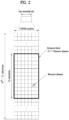
- FIG. 2 illustrates the structure of a downlink resource grid for the duration of one downlink slot.
- a downlink slot includes 7 OFDM symbols in the time domain and an RB includes 12 subcarriers in the frequency domain, which does not limit the scope of the present disclosure.
- a downlink slot may include 7 OFDM symbols in the case of the normal CP, whereas a downlink slot may include 6 OFDM symbols in the case of the extended CP.
- Each element of the resource grid is referred to as a resource element (RE).
- An RB includes 12x7 REs.
- the number of RBs in a downlink slot, NDL depends on a downlink transmission bandwidth.
- An uplink slot may have the same structure as a downlink slot.
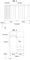
- FIG. 3 illustrates the structure of a downlink subframe.
- Up to three OFDM symbols at the start of the first slot in a downlink subframe are used for a control region to which control channels are allocated and the other OFDM symbols of the downlink subframe are used for a data region to which a PDSCH is allocated.
- Downlink control channels used in the 3GPP LTE system include a physical control format indicator channel (PCFICH), a physical downlink control channel (PDCCH), and a physical hybrid automatic repeat request (HARQ) indicator channel (PHICH).
- the PCFICH is located in the first OFDM symbol of a subframe, carrying information about the number of OFDM symbols used for transmission of control channels in the subframe.
- the PHICH delivers an HARQ acknowledgment/negative acknowledgment (ACK/NACK) signal in response to an uplink transmission.
- Control information carried on the PDCCH is called downlink control information (DCI).
- DCI transports uplink or downlink scheduling information, or uplink transmission power control commands for UE groups.
- the PDCCH delivers information about resource allocation and a transport format for a downlink shared channel (DL-SCH), resource allocation information about an uplink shared channel (UL-SCH), paging information of a paging channel (PCH), system information on the DL-SCH, information about resource allocation for a higher-layer control message such as a Random Access Response transmitted on the PDSCH, a set of transmission power control commands for individual UEs of a UE group, transmission power control information, voice over Internet protocol (VoIP) activation information, etc.
- a plurality of PDCCHs may be transmitted in the control region.
- a UE may monitor a plurality of PDCCHs.
- a PDCCH is formed by aggregating one or more consecutive control channel elements (CCEs).
- a CCE is a logical allocation unit used to provide a PDCCH at a coding rate based on the state of a radio channel.
- a CCE includes a plurality of RE groups.
- the format of a PDCCH and the number of available bits for the PDCCH are determined according to the correlation between the number of CCEs and a coding rate provided by the CCEs.
- An eNB determines the PDCCH format according to DCI transmitted to a UE and adds a cyclic redundancy check (CRC) to control information.
- the CRC is masked by an identifier (ID) known as a radio network temporary identifier (RNTI) according to the owner or usage of the PDCCH.
- ID identifier
- RNTI radio network temporary identifier
- the PDCCH may be masked by a cell-RNTI (C-RNTI) of the UE. If the PDCCH is for a paging message, the CRC of the PDCCH may be masked by a paging indicator Identifier (P-RNTI). If the PDCCH carries system information, particularly, a system information block (SIB), its CRC may be masked by a system information ID and a system information RNTI (SI-RNTI). To indicate that the PDCCH carries a random access response in response to a random access preamble transmitted by a UE, its CRC may be masked by a random access-RNTI (RA-RNTI).
- SIB system information block
- SI-RNTI system information RNTI
- RA-RNTI random access-RNTI
- FIG. 4 illustrates the structure of an uplink subframe.
- An uplink subframe may be divided into a control region and a data region in the frequency domain.
- a physical uplink control channel (PUCCH) carrying uplink control information is allocated to the control region and a physical uplink shared channel (PUSCH) carrying user data is allocated to the data region.
- PUSCH physical uplink shared channel
- a UE does not transmit a PUSCH and a PUCCH simultaneously.
- a PUCCH for a UE is allocated to an RB pair in a subframe. The RBs of the RB pair occupy different subcarriers in two slots. Thus it is said that the RB pair allocated to the PUCCH is frequency-hopped over a slot boundary.
- a packet is transmitted on a radio channel.
- the packet may be distorted during the transmission.
- a receiver should compensate for the distortion of the received signal using channel information.
- a transmitter transmits a signal known to both the transmitter and the receiver and the receiver acquires knowledge of channel information based on the distortion of the signal received on the radio channel. This signal is called a pilot signal or an RS.
- Tx transmission
- Rx reception
- the RSs may be divided into downlink RSs and uplink RSs.
- the uplink RSs include:
- the downlink RSs are categorized into:
- RSs may also be divided into two types according to their purposes: RS for channel information acquisition and RS for data demodulation. Since its purpose lies in that a UE acquires downlink channel information, the former should be transmitted in a broad band and received even by a UE that does not receive downlink data in a specific subframe. This RS is also used in a situation like handover. The latter is an RS that an eNB transmits along with downlink data in specific resources. A UE can demodulate the data by measuring a channel using the RS. This RS should be transmitted in a data transmission area.
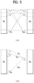
- FIG. 5 is a diagram illustrating a configuration of a wireless communication system having multiple antennas.
- transmit powers can be set different from each other for individual pieces of transmission information S 1 , S 2 , ⁇ , S N T , respectively. If the transmit powers are set to P 1 , P 2 , ⁇ , P N T , respectively, the transmission information with adjusted transmit powers can be represented as Equation 3.
- ⁇ can be represented as Equation 4 using diagonal matrix P of the transmission power.
- s ⁇ P 1 0 P 2 ⁇ 0 P N T
- s 1 s 2 ⁇ s N T Ps
- the weight matrix W serves to appropriately distribute the transmission information to each antenna according to a transport channel state.
- x 1 , x 2 , ⁇ , x N T can be expressed by using the vector X as follows.
- W ij denotes a weight between an i th Tx antenna and j th information. W is also called a precoding matrix.
- the channels may be distinguished according to Tx/Rx antenna indexes.
- a channel from the Tx antenna j to the Rx antenna i is denoted by h ij .
- h ij it is noted that the indexes of the Rx antennas precede the indexes of the Tx antennas in view of the order of indexes.
- FIG. 5(b) is a diagram illustrating channels from the N T Tx antennas to the Rx antenna i.
- the channels may be combined and expressed in the form of a vector and a matrix.
- AWGN Additional White Gaussian Noise
- the received signals can be expressed as follows.
- the number of rows and columns of the channel matrix H indicating the channel state is determined by the number of Tx and Rx antennas.
- the number of rows of the channel matrix H is equal to the number N R of Rx antennas and the number of columns thereof is equal to the number N T of Tx antennas. That is, the channel matrix H is an N R ⁇ N T matrix.
- the rank of the matrix is defined by the smaller of the number of rows and the number of columns, which are independent from each other. Accordingly, the rank of the matrix is not greater than the number of rows or columns.
- the rank rank ( H ) of the channel matrix H is restricted as follows. rank H ⁇ min N T N R
- the rank of a matrix can also be defined as the number of non-zero Eigen values when the matrix is Eigen-value-decomposed.
- the rank of a matrix can be defined as the number of non-zero singular values when the matrix is singular-value-decomposed.
- the physical meaning of the rank of a channel matrix can be the maximum number of channels through which different pieces of information can be transmitted.
- 'rank' for MIMO transmission indicates the number of paths capable of sending signals independently on specific time and frequency resources and 'number of layers' indicates the number of signal streams transmitted through the respective paths.
- a transmitting end transmits the number of layers corresponding to the rank number, one rank has the same meaning of the layer number unless mentioned specially.
- ICI inter-cell interference
- a specific node may transmit a representative synchronization signal and the other UEs may acquire synchronization using the representative synchronization signal.
- some nodes may transmit a D2D synchronization signal (D2DSS) and the remaining UEs may transmit and receive signals in synchronization with the D2DSS.
- D2DSS D2D synchronization signal
- D2DSSs may include a primary D2DSS (PD2DSS) or a primary sidelink synchronization signal (PSSS) and a secondary D2DSS (SD2DSS) or a secondary sidelink synchronization signal (SSSS).
- the PD2DSS may be configured to have a similar/modified/repeated structure of a Zadoff-chu sequence of a predetermined length or a primary synchronization signal (PSS).
- PSS primary synchronization signal
- the PD2DSS may use a different Zadoff-chu root index (e.g., 26, 37).
- the SD2DSS may be configured to have a similar/modified/repeated structure of an M-sequence or a secondary synchronization signal (SSS).
- SSS secondary synchronization signal
- the eNB serves as an SRN and the D2DSS is a PSS/SSS.
- the PD2DSS/SD2DSS follows UL subcarrier mapping scheme.
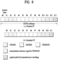
- FIG. 6 shows a subframe in which a D2D synchronization signal is transmitted.
- a physical D2D synchronization channel may be a (broadcast) channel carrying basic (system) information that a UE should first obtain before D2D signal transmission and reception (e.g., D2DSS-related information, a duplex mode (DM), a TDD UL/DL configuration, a resource pool-related information, the type of an application related to the D2DSS, etc.).
- the PD2DSCH may be transmitted in the same subframe as the D2DSS or in a subframe subsequent to the frame carrying the D2DSS.
- a DMRS can be used to demodulate the PD2DSCH.
- the SRN may be a node that transmits a D2DSS and a PD2DSCH.
- the D2DSS may be a specific sequence and the PD2DSCH may be a sequence representing specific information or a codeword produced by predetermined channel coding.
- the SRN may be an eNB or a specific D2D UE. In the case of partial network coverage or out of network coverage, the SRN may be a UE.
- a D2DSS may be relayed for D2D communication with an out-of-coverage UE.
- the D2DSS may be relayed over multiple hops.
- relay of an SS covers transmission of a D2DSS in a separate format according to a SS reception time as well as direct amplify-and-forward (AF)-relay of an SS transmitted by an eNB.
- AF direct amplify-and-forward
- an in-coverage UE may communicate directly with an out-of-coverage UE.
- FIG. 8 shows an example of a first UE (UE1), a second UE (UE2) and a resource pool used by UE1 and UE2 performing D2D communication.
- a UE corresponds to a terminal or such a network device as an eNB transmitting and receiving a signal according to a D2D communication scheme.
- a UE selects a resource unit corresponding to a specific resource from a resource pool corresponding to a set of resources and the UE transmits a D2D signal using the selected resource unit.
- UE2 corresponding to a receiving UE receives a configuration of a resource pool in which UE1 is able to transmit a signal and detects a signal of UE1 in the resource pool.
- a resource pool includes a plurality of resource units.
- a UE selects one or more resource units from among a plurality of the resource units and may be able to use the selected resource unit(s) for D2D signal transmission.
- FIG. 8(b) shows an example of configuring a resource unit. Referring to FIG. 8(b) , the entire frequency resources are divided into the N F number of resource units and the entire time resources are divided into the N T number of resource units.
- a resource pool can be repeated with a period of N T subframes.
- one resource unit may periodically and repeatedly appear.
- an index of a physical resource unit to which a logical resource unit is mapped may change with a predetermined pattern according to time to obtain a diversity gain in time domain and/or frequency domain.
- a resource pool may correspond to a set of resource units capable of being used by a UE intending to transmit a D2D signal.
- a resource pool can be classified into various types. First of all, the resource pool can be classified according to contents of a D2D signal transmitted via each resource pool. For example, the contents of the D2D signal can be classified into various signals and a separate resource pool can be configured according to each of the contents.
- the contents of the D2D signal may include a scheduling assignment (SA or physical sidelink control channel (PSCCH)), a D2D data channel, and a discovery channel.
- SA may correspond to a signal including information on a resource position of a D2D data channel, information on a modulation and coding scheme (MCS) necessary for modulating and demodulating a data channel, information on a MIMO transmission scheme, information on a timing advance (TA), and the like.
- MCS modulation and coding scheme
- the SA signal can be transmitted on an identical resource unit in a manner of being multiplexed with D2D data.
- an SA resource pool may correspond to a pool of resources that an SA and D2D data are transmitted in a manner of being multiplexed.
- the SA signal can also be referred to as a D2D control channel or a physical sidelink control channel (PSCCH).
- the D2D data channel (or, physical sidelink shared channel (PSSCH)) corresponds to a resource pool used by a transmitting UE to transmit user data. If an SA and a D2D data are transmitted in a manner of being multiplexed in an identical resource unit, D2D data channel except SA information can be transmitted only in a resource pool for the D2D data channel.
- REs which are used to transmit SA information in a specific resource unit of an SA resource pool, can also be used for transmitting D2D data in a D2D data channel resource pool.
- the discovery channel may correspond to a resource pool for a message that enables a neighboring UE to discover transmitting UE transmitting information such as ID of the UE, and the like.
- contents of D2D signal are identical to each other, it may use a different resource pool according to a transmission/reception attribute of the D2D signal.
- the D2D data channel or the discovery signal can be classified into a different resource pool according to a transmission timing determination scheme (e.g., whether a D2D signal is transmitted at the time of receiving a synchronization reference signal or the timing to which a prescribed timing advance is added) of a D2D signal, a resource allocation scheme (e.g., whether a transmission resource of an individual signal is designated by an eNB or an individual transmitting UE selects an individual signal transmission resource from a pool), a signal format (e.g., number of symbols occupied by a D2D signal in a subframe, number of subframes used for transmitting a D2D signal), signal strength from an eNB, strength of transmit power of a D2D UE, and the like.
- a transmission timing determination scheme e.g., whether a D2D signal is transmitted at the time
- a method for an eNB to directly designate a transmission resource of a D2D transmitting UE is referred to as a mode 1 (mode 3 in case of V2X). If a transmission resource region is configured in advance or an eNB designates the transmission resource region and a UE directly selects a transmission resource from the transmission resource region, it is referred to as a mode 2 (mode 4 in case of V2X). In case of performing D2D discovery, if an eNB directly indicates a resource, it is referred to as a type 2. If a UE directly selects a transmission resource from a predetermined resource region or a resource region indicated by the eNB, it is referred to as type 1.
- a mode-1 UE may transmit an SA (D2D control signal, or sidelink control information (SCI)) in resources configured by an eNB.
- SA D2D control signal, or sidelink control information (SCI)
- the eNB configures resources for D2D transmission.
- the mode-2 UE may select time-frequency resources from the configured resources and transmit an SA in the selected time-frequency resources.
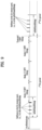
- An SA period may be defined as illustrated in FIG. 9 .
- a first SA period may start in a subframe spaced from a specific system frame by a predetermined offset, SAOffsetIndicator indicated by higher-layer signaling.
- Each SA period may include an SA resource pool and a subframe pool for D2D data transmission.
- the SA resource pool may include the first subframe of the SA period to the last of subframes indicated as carrying an SA in a subframe bitmap, saSubframeBitmap.
- the resource pool for D2D data transmission may include subframes used for actual data transmission through application of a time-resource pattern for transmission (T-RPT) or a time-resource pattern (TRP) in mode 1.
- T-RPT time-resource pattern for transmission
- TRP time-resource pattern
- the T-RPT may be applied repeatedly, and the last applied T-RPT may be truncated to be as long as the number of remaining subframes.
- a transmitting UE performs transmission at positions corresponding to 1s set in a T-RPT bitmap in an indicated T-RPT, and transmits one medium access control layer protocol data unit (MAC PDU) four times.
- MAC PDU medium access control layer protocol data unit
- a cooperative awareness message (CAM) of a periodic message type, a decentralized environmental notification message (DENM) of an event triggered message type, and so on may be transmitted.
- the CAM may deliver dynamic state information about a vehicle, such as a direction and a speed, static data of the vehicle, such as dimensions, an ambient illumination state, basic vehicle information such as details of a path, and so on.
- the CAM may be 50 bytes to 300 bytes in length.
- the CAM is broadcast, and its latency should be shorter than 100ms.
- the DENM may be generated, upon occurrence of an unexpected incident such as breakdown or an accident of a vehicle.
- the DENM may be shorter than 3000 bytes, and received by all vehicles within a transmission range.
- the DENM may have a higher priority than the CAM. Having a higher priority may mean that in the case of simultaneous transmission of messages at a UE, the UE transmits a higher-priority message above all, or a message having a higher priority earlier in time among the plurality of messages. From the perspective of multiple UEs, a message having a higher priority may be subjected to less interference than a message having a lower priority, to thereby have a reduced reception error probability. Regarding the CAM, the CAM may have a larger message size when it includes security overhead than when it does not.
- the UE may select resources semi-persistently. Specifically, for example, in the case where the UE transmits packets in every predetermined period, once the UE selects resources, the UE may keep the selected resources for a predetermined time within the packet transmission period, for stable interference measurement of other UEs. That is, a semi-persistent resource allocation method may be applied/used to/in D2D communication. The semi-persistent resource allocation method may advantageously enable neighbor UEs to stably measure interference, and stably maintain transmission resources, when a packet is generated in every predetermined period. Meanwhile, the UE may select multiple resources in consideration of multiple retransmissions.
- the semi-persistent resource allocation method may be based on sensing. That is, this method may be a sensing-based semi-persistent resource allocation method.
- this method may be a sensing-based semi-persistent resource allocation method.
- the UE may reserve resources outside a resource area or perform a transmission in resources different from resources used at an initial transmission. Specifically, as illustrated in FIG.
- the UE may transmit a packet every 100ms, and select resources (A in FIG. 10 ) within 100ms, for the packet transmission. Once the UE selects the resources and transmits a signal in the selected resources, the UE may also perform a transmission in the selected resources (A' in FIG. 10 ) during the next 100ms. The UE may perform this operation during transmission of a specific message (e.g., by setting a counter value at an initial resource selection, and maintaining the counter value by 1 (or decrementing the counter value by 1) each time a transport block (TB) is transmitted).
- a specific message e.g., by setting a counter value at an initial resource selection, and maintaining the counter value by 1 (or decrementing the counter value by 1) each time a transport block (TB) is transmitted.
- the period of a sidelink resource pool or the length of a bitmap for a sidelink resource pool configuration is not a multiple or factor of 100, it may occur that the next resources (A' in FIG. 10 ) are transmitted in a different resource pool from the initial transmission resource pool of the UE, or reserved resources do not belong to the sidelink resource pool.
- the UE may have to perform a transmission in a different resource area, cause unnecessary interference to another channel (e.g., a UL channel), or have to drop a packet to be transmitted.
- a UE may select resources for transmission of a plurality of data, and transmit the plurality of data in the selected resources.
- the UE is configured to perform the transmission based on sensing. If the UE fails in transmitting the data successively a predetermined number of or more times, the UE reselects resources.
- the selected resources may be repeated in every semi-persistent resource allocation period. That is, the UE selects data/packet transmission resources which will be used repeatedly in every semi-persistent resource allocation period by sensing, and transmits a plurality of data/packets and/or data and a retransmission of the data in the repeated resources in every period. If the UE fails in data/packet transmission successively a predetermined number of or more times in the selected/reserved resources, the UE reselects resources.
- resources are reserved semi-persistently in a specific resource area, if packets are dropped successively a predetermined number of or more times, resources are reselected. If resource reselection is performed even upon occurrence of one or two packet drops, the probable presence of multiple UEs performing reselection may result in unstable interference measurement.
- resource reselection may be performed restrictively, thereby preventing excessive resource reselection. Further, if resources are unavailable successively, data transmission may be performed in reselected resources without waiting until all of the reserved resources are gone, thereby increasing transmission reliability.
- the predetermined number based on which resource reselection is performed may be determined in consideration of one or more of factors including the number of UEs participating in D2D or V2X communication, the (average) speed of the UE, a network congestion state, a sensing threshold, the capability of the UE, and so on.
- the predetermined number may be determined by the network or the UE. In the former case, the predetermined number may be indicated to the UE by high-layer or physical-layer signaling.
- the resource reselection may be performed irrespective of a counter value set for resource reselection. Further, the selected resources may be indicated as available for data transmission and reception by a bitmap. Further, the bitmap may be applied repeatedly within an SFN period.
- resources are reserved semi-persistently in a specific resource area
- resource reselection is performed.
- resources are reserved semi-persistently in a specific resource area, if the resource area is changed in the middle of time, or resources outside the resource area are reserved, a packet outside the resource area is dropped, or resource reselection is performed irrespective of a counter value.
- the length of a resource area bitmap (the length of a resource pool bitmap) may be aligned with a semi-persistent resource allocation/configuration period.
- the length of the resource pool bitmap may be set to a multiple or factor of the semi-persistent resource allocation/configuration period. That is, the length of the bitmap may match a generation period of a CAM.
- the length of the resource area bitmap (the length of the resource pool bitmap) is also set to a factor or multiple of 100ms.
- the network may signal a resource area bitmap (a resource pool bitmap) and/or an offset at which the bitmap starts to be applied to the UE by a physical-layer or high-layer signal.
- UEs participating in the sidelink fill an SFN period (10240ms) by repeating a 100-ms bitmap, starting from a time obtained by applying the offset to subframe 0 of SFN 0. If the semi-persistent allocation/configuration period is Xms, a factor or multiple of X may be included/correspond in/to the length of a bitmap for a resource area configuration (the length of a resource pool bitmap).
- the offset may be set to 0 or no offset may be signaled.
- the offset is a value used to signal a resource area of an adjacent cell by the serving cell in an asynchronous network.
- the network may separately signal a bitmap for a plurality of resource areas to the UE, and the UE may assume that a sidelink signal is transmitted/received only in the positions of subframes corresponding to 1s in the bitmap.
- the 10240-ms period is filled by repeating the bitmap, and truncating a last one of the repeated bitmaps. For example, if a 100-ms resource pool bitmap is used on the assumption of a 100-ms semi-persistent resource allocation/configuration period, the bitmap is repeated, starting from subframe 0 of SFN 0, and the last of the repeated bitmaps is applied from its beginning to 40ms, with the remaining part truncated. This operation is intended to eliminate the ambiguity of a resource area, when UEs configure a resource area according to an SFN period, and the length of a resource area configuration bitmap does not match the SFN period.
- the length of a bitmap may be set to a common factor between a semi-persistent resource allocation period and an SFN period.
- a common factor (the greatest common factor) between a semi-persistent scheduling (SPS) period (the semi-persistent resource allocation/configuration period) and the SFN period (10240) is set as the length of a resource pool bitmap.
- SPS semi-persistent scheduling
- the resource area bitmap may be 10ms or 20ms long.
- the resource area bitmap may be 10ms, 20ms, or 40ms long.
- a packet generation period varies from 100ms up to 1000ms. If an available SPs period increases by a unit of 100ms, 100, 200, 300, ..., 1000ms may be available as the SPS period.
- the length of the resource pool bitmap is preferably determined to be the minimum of the greatest common factors between the respective available SPS periods and the SFN period (10240). Then, there may be no deviation from the resource area throughout the SPS operation.
- the network may signal configurable SPS periods by a physical-layer or high-layer signal.
- a bitmap indicating the upper and lower bounds of configurable SPS periods, configurable SPS period values, or used SPS periods e.g., if 100, 200, 400, and 800 are used among 100, 200, ..., 1000 is used, a bitmap of 1101000100
- these configurable SPS periods may be preset.
- the UE may select a specific one of the configurable SPS periods, and perform an SPS operation according to the selected SPS period.
- the network may use the minimum of common factors between the configurable SPS periods and 10240 as the length of a resource pool bitmap.
- the greatest common factors between the SPS periods and 10240 are 40, 80, 20, and 40, respectively, and thus the minimum of the greatest common factors, that is, 20 is used as the length of the resource pool bitmap.
- the length of the resource pool bitmap is set to a factor or multiple of the SPS period, it may occur that resources are reserved outside the resource area at the boundary of the SFN period. For example, since only 40ms of the last bitmap of the SFN period is used with the remaining part truncated, and the bitmap starts again in SFN 0, for a UE which has selected resources in the last 40ms, a subframe after the next 100ms may not be a sidelink resource area. As such, when resources reserved with an SPS period are not a sidelink resource area at the boundary of an SFN period, it may be regulated that a corresponding packet is dropped and/or resource reselection is necessarily performed irrespective of a counter value. Or it may be regulated that when SFN 0 returns, all UEs perform resource reselection.
- the scrambling sequence of the PSCCH may vary according to a subframe index so as to achieve a higher randomization gain.
- Proposal 1 In PC5 V2V, the scrambling sequence of the PSCCH may vary according to a subframe index.
- the scrambling sequence changes according to a subframe index.
- a DMRS sequence is a function of priority information. This differentiates a DMRS sequence having a certain priority from DMRS sequences having other priorities. The same mechanism is applicable to a scrambling sequence.
- the scrambling sequence of the PSSCH may be a function of priority information.
- Proposal 2 The scrambling sequence of the PSSCH may be a function of priority information.
- frequency hopping may not be necessary.
- Proposal 3 If independent resource selection is applied between retransmissions, frequency hopping is not used in PC5-based V2V of LTE Release 14.
- d should not be too large.
- the UE should exclude time resources beyond the latency requirements from a message generation time.
- dmax may be determined at the MAC layer. This exclusion may be incorporated in step 2.
- step 3 option 3-2 is preferable.
- Step 3-1 The UE measures the remaining PSSCH resources based on total received energy, prioritizes the measurements, and selects a subset.
- the subset includes X % of resources having the lowest energy.
- X is configurable.
- Step 3 Proposal 3: Option 3-2 is supported in step 3.
- retransmission resources for a transport block should be considered.
- TB transport block
- 'resource' should be clarified. The following two alternatives are available.
- Each SA reserves a transmission in a single subframe. Like a DSCH, each transmission involves an SA. It may be difficult to include such an independent resource allocation in one SA.
- the SA may require HARQ process ID, new data indicator (NDI), and redundancy version (RV) fields.
- NDI new data indicator
- RV redundancy version
- the UE selects an initial subframe n + d1, from subframe n+d1-a to subframe n+d1, and a is (pre-)configured by the network or by a fixed value.
- a is (pre-)configured by the network or by a fixed value.
- an independent SA transmission is similar to a DL asynchronous HARQ operation.
- the time difference between (re)transmissions of a TB may be limited by a threshold.
- Each SA may reserve all subsequent (re)transmissions.
- the following problem may occur. What combination of (re)transmission resource positions to be considered by the UE may become an issue. If an initial transmission and a retransmission take place at different frequency positions, an SA should present a multifrequency resource indication field. Therefore, the overhead of an SA bit size is generated.
- a method of indicating the time/frequency position of (re)transmission resources in a single SA may be problematic.
- a mechanism such as T-RPT may be used, or a plurality of time offsets between an SA and data may be indicated by the SA.
- Alternative 1 between the two alternatives is preferable.
- Alternative 1 may have a common design of SA content irrespective of association between an SA and data, and reduce the size of the SA content.
- the single carrier property should be considered.
- the UE selects multiple transmission resources, the UE should sequentially select the resources, and exclude the resources of previously selected subframe(s).
- Proposal 4 Each SA reserves a transmission in a single subframe.
- Proposal 5 When the UE selects multiple transmission resources, the UE should sequentially select the resources, and exclude the resources of previously selected subframe(s)
- the UE may select data resources based on sensing.
- a time interval is selected from a configurable range by a transmitting UE in a UE-autonomous resource selection mode.
- the time difference between an SA and data is transmitted by the SA.
- the UE first selects resources for associated data.
- the steps of data resource selection may be applied for SA resource selection.
- a threshold and a value X may be different from those used in the data resource selection.
- Proposal 7 The steps of data resource selection for SA resources may be applied to SA positions associated with selected data resources (e.g., time positions limited by a configured range of time gaps between an SA and data).
- a main advantage of a reservation operation lies in that a UE estimates the interference level of upcoming resources based on the sensing result of a previous time window. Reselection of many resources in this operation may lead to performance degradation. To reduce unnecessary resource reselection, SA resources should be reselected only when associated data resources are reselected.
- Proposal 8 SA resources are reselected by associated data resources
- a CAM may be generated every 100ms to 1000ms under circumstances. Since a vehicle does not move instantaneously, the location, direction, and speed of the vehicle may change gradually. Accordingly, a UE may estimate a time when a CAM is generated, for a short time. Further, with application of an appropriate timing margin to absorb the timing jitter of a message generation period, the resource drop problem that when a packet does not arrive, a UE cannot use reserved resources may be overcome. For these reasons, there is no need for reserving resources every 100ms, and an excessive resource reservation may occur every 100ms. In this operation, a reservation period j is explicitly signaled by an SA.
- Proposal 1 A reservation period i is explicitly signaled.
- Proposal 2 J is fixed to 1 in the LTE standard specification.
- congestion level (number of busy data (or SA) resources in T)/(number of total data (or SA) resources in T).
- T represents a measurement time interval, which may be fixed or (pre)configured by the network. If the measured DMRS power (such as RSRP) or received energy (such as RSSI) exceeds a threshold or is indicated by SA decoding, the resources are declared as ⁇ in use' Each resource may be a PRB or a PRB group. For example, the resource may be identical to a sub-channel. The threshold may be (pre)configured. The UE may perform measurement in each resource pool. The UE may calculate the average of the measurements of resource pools. However, if resource pools are divided according to UE types, for example, if one resource pool is for a pedestrian UE (P-UE) and another resource pool is for a vehicle UE, per-resource pool measurements should also be separated.
- P-UE pedestrian UE
- per-resource pool measurements should also be separated.
- a congestion level measurement may be used for applying transmission parameters.
- the congestion level measurement may be used to determine a message size, a message generation speed, an MCS, an RB size, the number of retransmissions, and transmission power.
- two solutions may be considered.
- One of the solutions is an application layer-based solution, and the other is a wireless layer-based solution.
- the UE reports a congestion measurement, and the application layer indicates or changes a packet size and/or a message generation speed.
- the wireless layer may adjust an MCS, an RB size, the number of retransmissions, and power.
- the UE may report its congestion level measurement to the eNB.
- the eNB may control a resource pool size and a transmission parameter range.
- Proposal 2 In view of the limited time of the V2V WI, it is preferable to defer reporting a congestion level measurement to an eNB and defining a related UE operation to the V2X WI.
- RAN1 #84b it was determined to multiplex an SA and an associated data pool in frequency division multiplexing (FDM) from the perspective of a system.
- the SA and its associated data may occupy contiguous or non-contiguous RBs, and may be transmitted in the same or different TTIs.
- the FDMed resource pool design offers the following advantages.
- the FDMed resource pool may decrease a latency.
- the FDMed resource structure enables immediate transmission of an SA and associated data.
- a TDMed structure requires transmission of an SA and data in respective resource pools.
- Another advantage is that in-band emission is mitigated during SA transmission.
- more SAs are transmitted in an SA pool, thereby increasing mutual in-band emission. Further, this method may relieve the half duplex problem.
- FDMed resource pool configuration FDMed and TDMed transmissions of an SA and associated data are supported from the perspective of a single UE.
- a TDMed resource pool structure for an SA and data is designed, a TDMed SA and data that does not satisfy the agreements of RAN#1 84b (e.g., an SA and associated data transmitted in the same TTI) may be supported.
- Proposal 1 SA resources and data resources are always FDMed from the perspective of a system.
- an SA resource pool bitmap and a data resource pool bitmap are transmitted by individual signals because two resources pools are TDMed, while a single bitmap may be transmitted in a V2V signal in order to configure a sidelink subframe common to an SA pool and a data pool.
- Proposal 2 In PC5-based V2V, a single bitmap is signaled in order to configure sidelink subframes for both of an SA and a data pool.
- a sidelink control (SC) period has been defined to configure a resource pool.
- SC sidelink control
- the concept of an SC period is not necessary in an infinite V2V resource structure.
- a resource pool bitmap is repeated within an SFN (10240 ms).
- Proposal 3 The concept of an SC period is not necessary for a resource pool configuration. A resource pool bitmap is repeated within an SFN (10240 ms).
- a general message transmission period is a multiple of 100ms.
- the length of a resource pool which is ⁇ 40, 80, 160, 320 ⁇ msec in FDD and TDD configurations 1 to 5, ⁇ 70, 140, 280 ⁇ msec in TDD configuration 0, and ⁇ 60, 120, 240 ⁇ msec in TDD configuration 6, is not divisible by 100ms. That is, when the UE reserves resources every 100ms, some resources may not reside within a sidelink resource pool.
- bitmap lengths such as 10 (a common divisor between 100 and 10240) and 20 (the greatest common factor between 100 and 10240) are proposed.
- the bitmap length is preferably the greatest common factor between an SPS period (100, 200, ..., 1000) and an SFN period (10240). If multiple SPS periods are supported, the bitmap length should be equal to the minimum of the maximum common denominators of the SPS periods.
- a legacy resource pool bitmap length is better for co-existence between PC5 and Uu.
- a new introduced bitmap is suitable for a V2V dedicated carrier.
- the network may select an appropriate bitmap length according to a situation.
- Proposal 4 In PC5-based V2V, new bitmap lengths, for example, 10 and 20 (common divisors between 100 and 10240) are additionally used/introduced for a resource pool configuration.
- the network may select an appropriate bitmap length according to a situation. For example, a legacy bitmap length may be used for a shared carrier, whereas a new bitmap length may be used for a dedicated carrier.
- some of reserved resources may be outside a resource pool. In this case, since a packet may not be transmitted within the resource pool, the packet is dropped. To avoid packet loss, if some of reserved resources are located outside a resource pool, resource reselection may be triggered.
- Proposal 5 If reserved resources are located outside a resource pool, a packet is dropped, and resource reselection may be triggered.
- a signaling method for an SA and a data pool as defined in LTE Rel-12 may be reused. Starting and ending offsets, and a subband size are signaled by the network.
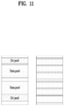
- RAN1 #85 it was agreed to allow a resource pool definition in which an SA and associated data transmitted in the same subframe are always adjacent.
- FIG. 11 illustrates exemplary resource pools. This resource pool structure may not be implemented by the frequency resource pool signaling of LTE Rel-12. Accordingly, there is a need for a new method of additionally supporting an interleaved SA and data pool. The new signaling requires new information such as the number of subbands.
- Proposal 6 The following two methods may be used to indicate frequency resources of a resource pool.
- One of the methods is to reuse the LTE Rel-12 signaling method for an SA and a data pool.
- An SA and data may be used in TDM or FDM in non-adjacent PRBs.
- the other method is a new method of additionally supporting an interleaved SA and data pool. This is used for an SA/data FDMed in adjacent PRBs.
- a sensing granularity may be based on a sub-channel size.
- a sub-channel includes a group of RBs in the same subframe. To satisfy a PSD regulation in an ITS carrier, each sub-channel may include distributed RBs.
- the sub-channel size of a resource pool may be configured by the eNB or preconfigured. The sub-channel size should be equal in the resource pool. Different subchannels should have separate groups of RBs.
- a frequency resource allocation granularity is equal to the size of a sub-channel in order to reduce the number of indication bits.
- FIG. 12 illustrates an example of sub-channelization.
- Proposal 7 Sub-channelization is supported for PC5-based V2V.
- Proposal 1 The same size of SCI contents are designed irrespective of a resource pool structure and the time/frequency resources of an SA and associated data.
- Sequence generation or source ID A V2V operation is broadcast and seeks safety, which obviates the need for a group destination ID. However, to randomize a scrambling sequence and DMRS sequence of data, some ID may be included in an SA. A source ID from a higher layer may be an option for randomization. The 8 LSBs of a destination ID are replaced with those of a source ID. As another option, an explicit field may be delivered in an SA.
- Time offset between PSCCH and PSSCH In RAN1 #84bis, it was agreed that a scheduling timing between an SA and associated data is variable. To support this flexibility, a time offset between the SA and the data may be indicated by the SA. If the time offset is 0, the SA and its associated data may be FDMed from the perspective of a single UE. Otherwise, the time offset is not 0, and the SA and the data may be TDMed according to the time offset.
- This field indicates the periodicity of reservation. For i, 4 bits may be assumed to indicate in [0, 10].
- a V2V SSSS uses a sequence of a subframe-5 SSS to avoid synchronization source confusion between a D2D UE and a V2V UE.
- a DMRS symbol position of a PSBCH for V2V is different from a DMRS symbol position as defined in legacy LTE Rel-12/13.
- Proposal 1 An SSSS for V2V uses a sequence of a subframe-5 SSS.
- SLSS and PSBCH transmission of a UE is supported for PC5-based V2V.
- the LTE Rel-12/13 synchronization procedure (e.g., synchronization reference priority) is the starting point, and PBSCH contents are discussed later.
- a GNSS or a GNSS equivalent is at the highest priority of synchronization source for time and frequency when a vehicle UE directly receives the GNSS or the GNSS equivalent with sufficient reliability and does not detect any cell in any carrier.”
- RAN1 needs to study the impact of this existing agreement on Uu operation.
- Priority of synchronization source includes at least transmission timing reference.
- FFS whether there is any differentiation depending on whether eNB is synchronized to GNSS in the corresponding SLSS transmissions
- • SLSS transmitted from out-coverage UE directly synchronized with GNSS or GNSS equivalent with sufficient reliability is differentiated from SLSS_net with in coverage indicator 1
- FFS Definition of SLSS_net, SLSS_oon - FFS: GNSS or GNSS equivalent priority
- Working assumption Priority of SLSS transmitted from in-coverage UE directly synchronized with GNSS or GNSS equivalent with sufficient reliability is the same as that of SLSS_net with in coverage indicator 1
- FFS SLSS transmitted from in-coverage UE using GN
- the priority of an SLSS transmitted from an in-coverage UE directly synchronized with the GNSS is equal to the priority of SLSS_net with an in-coverage indicator set to 1. Further, an SLSS transmitted from an out-coverage UE directly synchronized with the GNSS is differentiated from SLSS_net. The priority of the SLSS transmitted from the out-coverage UE directly synchronized with the GNSS is equal to that of SLSS_net with a non-volatile indicator 1 because there is no reason to differentiate GNSS-based synchronization signals between an in-coverage UE and an out-coverage UE.
- Proposal 2 One ID of SLSS_net is reserved for a GNSS-based synchronization signal. Eventually, the ID + 168 is reserved for a direct GNSS-based UE
- Proposal 3 For out-of-coverage, the priorities of synchronization sources are given in Table 4 below.
- An SLSS is always lower than an eNB. Otherwise, a new RRM requirement needs to be implemented to test synchronization reference transition from the eNB to the SLSS. Considering the low priority of this issue, the benefit is not clear.
- the UE may derive a timing reference from one of a Uu carrier and an eNB carrier. This function has already been specified in LTE Rel-13.
- the eNB may indicate a carrier to be used for a timing reference and DL measurements in a PC5 carrier.
- Proposal 5 A reserved bit size may be changed in order to avoid poor BLER performance of the PSBCH.
- the SLSS/PSBCH period is 200ms. However, this period is not divisible by the SFN period, which may result in detection failure of a synchronization signal between SFN periods. Particularly, the PSBCH decoding performance of a single shot may not be appropriate at a high speed. In this case, the UE should obtain a D2D frame number (DFN) by accumulating multiple PSBCH receptions or attempt multiple decodings for multiple PSBCH receptions. If the 200-ms SLS/PSBCH period is used, the UE may not accumulate multiple SLSSs/PSBCHs at a boundary of the SFN period. As a result, a synchronization latency may increase.
- D2D frame number D2D frame number
- the SFN period should be divisible by the SLSS/PSBCH period.
- the SLSS/PSBCH period should be 80 or 160ms.
- an eNB or a relay node may use the proposed methods.
- FIG. 13 is a block diagram of a transmission point and a UE according to an embodiment of the present disclosure.
- a transmission point 10 may include a receiver 11, a transmitter 12, a processor 13, a memory 14, and a plurality of antennas 15.
- the plurality of antennas 15 mean that the transmission point 10 supports MIMO transmission and reception.
- the receiver 11 may receive various UL signals, data, and information from a UE.
- the transmitter 12 may transmit various DL signals, data, and information to a UE.
- the processor 13 may provide overall control to the transmission point 10.
- the processor 13 of the transmission point 10 may process requirements of each of the foregoing embodiments.
- the processor 13 of the transmission point 10 may function to compute and process information received by the transmission point 10 and information to be transmitted to the outside.
- the memory 14 may store the computed and processed information for a predetermined time, and may be replaced by a component such as a buffer (not shown).
- a UE 20 may include a receiver 21, a transmitter 22, a processor 23, a memory 24, and a plurality of antennas 15.
- the plurality of antennas 25 mean that the UE 20 supports MIMO transmission and reception.
- the receiver 21 may receive various DL signals, data, and information from an eNB.
- the transmitter 22 may transmit various UL signals, data, and information to an eNB.
- the processor 23 may provide overall control to the UE 20.
- the processor 23 of the UE 20 may process requirements of each of the foregoing embodiments. Specifically, the processor may select resources to transmit a plurality of data, and transmit the plurality of data in the selected resources.
- the UE is configured to perform a transmission by sensing. If the UE fails in transmitting the data successively a predetermined number or more times, the UE may perform resource reselection.
- the processor 23 of the UE 20 may also perform a function of computationally processing information received by the UE 20 and information to be transmitted to the outside, and the memory 24 may store the computationally processed information and the like for a predetermined time and may be replaced by a component such as a buffer (not shown).
- the specific configuration of the transmission point apparatus and the UE may be implemented such that the details described in the various embodiments of the present disclosure may be applied independently or implemented such that two or more of the embodiments are applied at the same time. For clarity, redundant description is omitted.
- the description of the transmission point 10 is applicable in the same manner to a relay as a DL transmission entity or a UL reception entity
- the description of the UE 20 is applicable in the same manner to the relay as a DL reception entity and a UL transmission entity.
- the embodiments of the present disclosure may be implemented through various means, for example, hardware, firmware, software, or a combination thereof.
- the embodiments of the present disclosure may be achieved by one or more application specific integrated circuits (ASICs), digital signal processors (DSPs), digital signal processing devices (DSPDs), programmable logic devices (PLDs), field programmable gate arrays (FPGAs), processors, controllers, microcontrollers, microprocessors, etc.
- ASICs application specific integrated circuits
- DSPs digital signal processors
- DSPDs digital signal processing devices
- PLDs programmable logic devices
- FPGAs field programmable gate arrays
- processors controllers, microcontrollers, microprocessors, etc.
- a method according to embodiments of the present disclosure may be implemented in the form of a module, a procedure, a function, etc.
- Software code may be stored in a memory unit and executed by a processor.
- the memory unit is located at the interior or exterior of the processor and may transmit and receive data to and from the processor via various known means.
Landscapes
- Engineering & Computer Science (AREA)
- Signal Processing (AREA)
- Computer Networks & Wireless Communication (AREA)
- Mobile Radio Communication Systems (AREA)
- Input Circuits Of Receivers And Coupling Of Receivers And Audio Equipment (AREA)
- Burglar Alarm Systems (AREA)
Claims (13)
- Verfahren zum Verarbeiten eines Sidelink-Signals, das von einem Endgerät (20) durchgeführt wird, wobei das Verfahren umfasst:Empfangen, durch Signalisierung höherer Schichten, von Informationen bezüglich einer Ressourcen-Wiederauswahlbedingung,Auswählen, basierend auf dem Erfassen, periodischer Ressourcen, die eine semipersistente Periode in einem Ressourcenbereich aufweisen, der im Endgerät (20) zum Übertragen mehrerer Sidelink-Dateneinheiten konfiguriert ist; undAbbrechen einer oder mehrerer Sidelink-Übertragungen auf den ausgewählten periodischen Ressourcen,Bestimmen einer ersten Anzahl, die sich auf eine Anzahl von aufeinanderfolgenden abgebrochenen Sidelink-Übertragungen in den periodischen Ressourcen bezieht, die für die Vielzahl von Sidelink-Dateneinheiten ausgewählt wurden;Durchführen einer Ressourcen-Wiederauswahl basierend auf der Ressourcen-Wiederauswahlbedingung,wobei die Ressourcen-Wiederauswahlbedingung eine erste Bedingung beinhaltet, die erfüllt ist, basierend darauf, dass die erste Anzahl zu einer spezifischen Anzahl wird,die im Endgerät (20) durch die Signalisierung höherer Schichten konfiguriert ist,wobei die spezifische Anzahl, die im Endgerät (20) durch die Signalisierung höherer Schichten konfiguriert ist, größer als 1 ist,
undwobei, basierend darauf, dass die erste Anzahl die spezifische Anzahl wird, die Ressourcen-Wiederauswahl unabhängig von einem Zähler durchgeführt wird, der sich auf die Ressourcen-Wiederauswahl bezieht. - Verfahren nach Anspruch 1, wobei die periodischen Ressourcen basierend auf einer Bitmap ausgewählt werden, die anzeigt, ob eine entsprechende Ressource für Datenübertragung und -empfang verfügbar ist.
- Verfahren nach Anspruch 2, wobei die Bitmap wiederholt innerhalb einer Periode der Systemrahmenanzahl, SFN, angewendet wird.
- Verfahren nach Anspruch 3, wobei eine Länge der Bitmap ein gemeinsamer Faktor zwischen einer Ressourcenzuweisungsperiode des Ressourcenbereichs und der SFN-Periode ist.
- Verfahren nach einem der vorhergehenden Ansprüche, ferner umfassend: Bestimmen, durch das Endgerät (20), dass die erste Bedingung nicht erfüllt ist, wenn die Anzahl der Male der einen oder der mehreren abgebrochenen Sidelink-Übertragungen geringer als die spezifische Anzahl ist oder wenn die eine oder die mehreren abgebrochenen Sidelink-Übertragungen nicht aufeinanderfolgend sind.
- Verfahren nach einem der vorhergehenden Ansprüche, wobei die Ressourcen-Wiederauswahlbedingung eine Bedingung beinhaltet, die erfüllt ist, wenn der konfigurierte Ressourcenbereich geändert wird.
- Verfahren nach einem der vorhergehenden Ansprüche, wobei der Ressourcenbereich ein Sidelink-Ressourcenpool ist, der im Endgerät (20) konfiguriert ist.
- Verfahren nach einem der vorhergehenden Ansprüche, wobei das Endgerät (20) eine Benutzerausrüstung, UE, ist, die konfiguriert ist, um in einem drahtlosen Kommunikationssystem, das auf der 3. Generation eines Partnerschaftsprojekts, 3GPP, basiert, betrieben zu werden.
- Endgerät (20), das konfiguriert ist, um ein Signal für drahtlose Kommunikation zu verarbeiten, wobei das Endgerät (20) umfasst:einen Speicher (24), der konfiguriert ist, um Programmcodes zu speichern; undeinen Prozessor (23), der konfiguriert ist, um die Programmcodes auszuführen,wobei der Prozessor (23) ferner konfiguriert ist, um das Verfahren nach einem der Ansprüche 1-8 abzuwickeln.
- Endgerät (20) nach Anspruch 9, wobei das Endgerät (20) eine anwendungsspezifische integrierte Schaltung, ASIC, oder ein digitales Signalverarbeitungsgerät umfasst.
- Endgerät (20) nach Anspruch 9, ferner umfassend:
einen Transceiver (21, 22), der konfiguriert ist, um ein drahtloses Signal mittels Steuerung des Prozessors (23) zu übertragen oder zu empfangen. - Endgerät (20) nach Anspruch 11, wobei das Endgerät (20) eine Benutzerausrüstung, UE, ist, die konfiguriert ist, um in einem drahtlosen Kommunikationssystem, das auf der 3. Generation eines Partnerschaftsprojekts, 3GPP, basiert, betrieben zu werden.
- Medium (24), das durch einen Prozessor (23) lesbar ist, und darauf Programmcodes aufgezeichnet sind, die, wenn sie von einem Prozessor eines Computers ausgeführt werden, den Computer veranlassen, das Verfahren nach einem der Ansprüche 1 bis 8 abzuwickeln.
Applications Claiming Priority (4)
| Application Number | Priority Date | Filing Date | Title |
|---|---|---|---|
| US201662373972P | 2016-08-11 | 2016-08-11 | |
| US201662374742P | 2016-08-12 | 2016-08-12 | |
| US201662374710P | 2016-08-12 | 2016-08-12 | |
| PCT/KR2017/008777 WO2018030854A1 (ko) | 2016-08-11 | 2017-08-11 | 무선 통신 시스템에서 단말이 다른 단말에게 데이터를 전송하는 방법 |
Publications (3)
| Publication Number | Publication Date |
|---|---|
| EP3499994A1 EP3499994A1 (de) | 2019-06-19 |
| EP3499994A4 EP3499994A4 (de) | 2020-04-22 |
| EP3499994B1 true EP3499994B1 (de) | 2024-04-24 |
Family
ID=61163046
Family Applications (1)
| Application Number | Title | Priority Date | Filing Date |
|---|---|---|---|
| EP17839871.5A Active EP3499994B1 (de) | 2016-08-11 | 2017-08-11 | Verfahren, in dem ein endgerät daten an ein anderes endgerät in einem drahtloskommunikationssystem überträgt |
Country Status (6)
| Country | Link |
|---|---|
| US (2) | US11330560B2 (de) |
| EP (1) | EP3499994B1 (de) |
| JP (2) | JP6921181B2 (de) |
| KR (2) | KR102426409B1 (de) |
| CN (1) | CN109804683B (de) |
| WO (1) | WO2018030854A1 (de) |
Families Citing this family (25)
| Publication number | Priority date | Publication date | Assignee | Title |
|---|---|---|---|---|
| JP6921181B2 (ja) | 2016-08-11 | 2021-08-18 | エルジー エレクトロニクス インコーポレイティド | 無線通信システムにおいて端末が他の端末にデータを伝送する方法 |
| CN107889073B (zh) * | 2016-09-30 | 2022-05-24 | 北京三星通信技术研究有限公司 | 一种v2x通信中的发送资源确定方法和设备 |
| CN115002910A (zh) | 2016-09-30 | 2022-09-02 | 北京三星通信技术研究有限公司 | 一种v2x通信中的发送资源确定方法和设备 |
| CN110392431A (zh) | 2018-04-19 | 2019-10-29 | 中兴通讯股份有限公司 | 一种实现边链路资源配置的方法、装置及系统 |
| CN112205043A (zh) * | 2018-05-30 | 2021-01-08 | 株式会社Ntt都科摩 | 通信装置 |
| JP7179856B2 (ja) * | 2018-08-09 | 2022-11-29 | 株式会社Nttドコモ | 端末及び通信方法 |
| CN112640346A (zh) * | 2018-08-09 | 2021-04-09 | 康维达无线有限责任公司 | 用于5g ev2x的侧链路上的广播、多播和单播 |
| WO2020032760A1 (ko) * | 2018-08-10 | 2020-02-13 | 엘지전자 주식회사 | 무선 통신 시스템에서 피드백 신호를 수신하는 방법 및 단말 |
| CN112771961A (zh) * | 2018-09-27 | 2021-05-07 | 瑞典爱立信有限公司 | 对已配置许可的动态灵活配置 |
| CN112823561A (zh) * | 2018-11-01 | 2021-05-18 | 苹果公司 | 用于nr v2x侧行链路通信的qos感知拥塞控制、资源分配和设备内共存解决方案 |
| US11071091B2 (en) * | 2019-01-10 | 2021-07-20 | At&T Intellectual Property I, L.P. | Contention level signaling for resource pools |
| CN113273121B (zh) * | 2019-01-11 | 2022-11-29 | 上海诺基亚贝尔股份有限公司 | 用于测量侧链路接收信号强度的方法、设备和计算机可读介质 |
| CN111263439A (zh) * | 2019-01-18 | 2020-06-09 | 维沃软件技术有限公司 | 资源分配的方法和设备 |
| CN111263469B (zh) * | 2019-01-18 | 2022-02-15 | 维沃移动通信有限公司 | 确定参数值的方法和设备 |
| CN111294162B (zh) * | 2019-03-28 | 2022-09-16 | 展讯通信(上海)有限公司 | V2x传输方法及装置、存储介质、用户设备 |
| US20220216956A1 (en) * | 2019-05-10 | 2022-07-07 | Ntt Docomo, Inc. | User equipment and communication method |
| KR20220079820A (ko) * | 2019-10-04 | 2022-06-14 | 텔레폰악티에볼라겟엘엠에릭슨(펍) | Lte-m 및 nb-iot를 위한 효율적인 자원 예약 |
| CN112788669A (zh) * | 2019-11-06 | 2021-05-11 | 维沃移动通信有限公司 | 一种信息处理方法及终端 |
| US11611853B2 (en) * | 2020-03-31 | 2023-03-21 | Qualcomm Incorporated | Sidelink group management for transmit power controlled group communications |
| KR102614859B1 (ko) * | 2020-04-10 | 2023-12-19 | 엘지전자 주식회사 | Nr v2x에서 sci 상의 ndi 값을 결정하는 방법 및 장치 |
| CN113708889A (zh) * | 2020-05-22 | 2021-11-26 | 维沃移动通信有限公司 | 数据传输方法和设备 |
| WO2021253307A1 (en) * | 2020-06-18 | 2021-12-23 | Qualcomm Incorporated | Downlink control information indication for passive sensing |
| WO2022032422A1 (en) * | 2020-08-10 | 2022-02-17 | Qualcomm Incorporated | Shared resource allocation |
| US20240023069A1 (en) * | 2020-10-22 | 2024-01-18 | Lenovo (Beijing) Limited | Methods and apparatuses for sidelink control information reception |
| CN115038170A (zh) * | 2021-03-03 | 2022-09-09 | 深圳市万普拉斯科技有限公司 | 通信处理方法、装置、用户设备和存储介质 |
Family Cites Families (12)
| Publication number | Priority date | Publication date | Assignee | Title |
|---|---|---|---|---|
| US9191961B2 (en) | 2011-06-17 | 2015-11-17 | Lg Electronics Inc. | Method for allocating wireless resources in wireless access system and device therefore |
| CN102932919B (zh) * | 2011-08-10 | 2017-10-20 | 中兴通讯股份有限公司 | 上行链路探测参考信号的资源配置方法及装置 |
| US10172115B2 (en) * | 2013-08-09 | 2019-01-01 | Lg Electronics Inc. | Method and apparatus for conducting device-to-device communication in wireless communication system |
| JP2017504242A (ja) * | 2013-12-06 | 2017-02-02 | 富士通株式会社 | D2dディスカバリー信号を送信する方法及び装置並びに通信システム |
| ES2663854T3 (es) | 2014-01-31 | 2018-04-17 | Sony Corporation | Dispositivo y procedimientos de comunicaciones |
| US20160381690A1 (en) * | 2014-03-10 | 2016-12-29 | Lg Electronics Inc. | Method for allocating resources in wireless communication system supporting device-to-device communication, and apparatus therefor |
| KR20160018244A (ko) | 2014-08-08 | 2016-02-17 | 주식회사 아이티엘 | D2d 통신을 위한 d2d 데이터 자원을 결정하는 방법 및 장치 |
| EP3214880B1 (de) | 2014-11-19 | 2019-09-25 | Huawei Technologies Co., Ltd. | Nachrichtenübertragungsverfahren, benutzergerät, basisstation und system |
| US20160295624A1 (en) * | 2015-04-02 | 2016-10-06 | Samsung Electronics Co., Ltd | Methods and apparatus for resource pool design for vehicular communications |
| US10383147B2 (en) * | 2015-12-28 | 2019-08-13 | Samsung Electronics Co., Ltd. | Methods and apparatus for resource collision avoidance in vehicle to vehicle communication |
| US10425959B2 (en) * | 2016-05-13 | 2019-09-24 | Samsung Electronics Co., Ltd. | Method and device for transmitting data |
| JP6921181B2 (ja) | 2016-08-11 | 2021-08-18 | エルジー エレクトロニクス インコーポレイティド | 無線通信システムにおいて端末が他の端末にデータを伝送する方法 |
-
2017
- 2017-08-11 JP JP2019507833A patent/JP6921181B2/ja active Active
- 2017-08-11 KR KR1020217023502A patent/KR102426409B1/ko active IP Right Grant
- 2017-08-11 US US16/324,887 patent/US11330560B2/en active Active
- 2017-08-11 WO PCT/KR2017/008777 patent/WO2018030854A1/ko unknown
- 2017-08-11 EP EP17839871.5A patent/EP3499994B1/de active Active
- 2017-08-11 KR KR1020197007029A patent/KR102284372B1/ko active IP Right Grant
- 2017-08-11 CN CN201780062618.2A patent/CN109804683B/zh active Active
-
2021
- 2021-07-27 JP JP2021122265A patent/JP7285887B2/ja active Active
-
2022
- 2022-04-04 US US17/712,705 patent/US11889476B2/en active Active
Non-Patent Citations (2)
| Title |
|---|
| ERICSSON: "Discussion on V2X PC5 Scheduling, Resource Pools and Resource Patterns", vol. RAN WG1, no. Busan, South Korea; 20160411 - 20160415, 14 May 2016 (2016-05-14), XP051096183, Retrieved from the Internet <URL:http://www.3gpp.org/ftp/tsg_ran/WG1_RL1/TSGR1_85/Docs/> [retrieved on 20160514] * |
| QUALCOMM INCORPORATED: "Resource reselection counter and triggering conditions", vol. RAN WG1, no. Athens, Greece; 20170213 - 20170217, 12 February 2017 (2017-02-12), XP051209674, Retrieved from the Internet <URL:http://www.3gpp.org/ftp/Meetings_3GPP_SYNC/RAN1/Docs/> [retrieved on 20170212] * |
Also Published As
| Publication number | Publication date |
|---|---|
| JP2019525655A (ja) | 2019-09-05 |
| CN109804683A (zh) | 2019-05-24 |
| KR20190034668A (ko) | 2019-04-02 |
| KR102426409B1 (ko) | 2022-07-28 |
| US11889476B2 (en) | 2024-01-30 |
| EP3499994A1 (de) | 2019-06-19 |
| US11330560B2 (en) | 2022-05-10 |
| JP6921181B2 (ja) | 2021-08-18 |
| US20220232526A1 (en) | 2022-07-21 |
| CN109804683B (zh) | 2023-08-04 |
| KR102284372B1 (ko) | 2021-08-02 |
| JP2021170832A (ja) | 2021-10-28 |
| JP7285887B2 (ja) | 2023-06-02 |
| EP3499994A4 (de) | 2020-04-22 |
| WO2018030854A1 (ko) | 2018-02-15 |
| US20210289473A1 (en) | 2021-09-16 |
| KR20210095239A (ko) | 2021-07-30 |
Similar Documents
| Publication | Publication Date | Title |
|---|---|---|
| US11889476B2 (en) | Method whereby terminal transmits data to another terminal in wireless communication system | |
| JP6707188B2 (ja) | 無線通信システムにおいて端末のpscch及びpsschの送受信方法及び装置 | |
| US11412485B2 (en) | Method and device for selecting resource and transmitting PSSCH in wireless communication system | |
| EP3522630A1 (de) | Verfahren und vorrichtung zur auswahl einer ressource und pssch-übertragung in einem drahtloskommunikationssystem | |
| EP3499781A1 (de) | Verfahren und vorrichtung für endgerät zur übertragung von d2d-daten in einem drahtloskommunikationssystem | |
| US10541848B2 (en) | Method and apparatus for generating and transmitting reference signal and data in wireless communication system | |
| EP3444990A1 (de) | Sidelink-signal-sende-/-empfangsverfahren eines ue in einem drahtloskommunikationssystem | |
| US10973033B2 (en) | Method and device for data transmission and resource selection by means of terminal measurement in wireless communication system | |
| US11191047B2 (en) | Method and apparatus for allowing user equipment to transmit and receive synchronization signal in plurality of component carriers in wireless communication system | |
| EP3579631A1 (de) | Verfahren, mit dem das endgerät das kanalbelegungsverhältnis (cr) misst und eine übertragung in einem drahtloskommunikationssystem durchführt, und vorrichtung | |
| US10849010B2 (en) | Method and apparatus for transmitting SA and data associated with congestion control in wireless communication system | |
| US10925059B2 (en) | Method and apparatus for transmitting sidelink signal in wireless communication system | |
| EP3648520B1 (de) | Verfahren und vorrichtung für ein benutzergerät zur übertragung von signalen in einem drahtlosen kommunikationssystem mit unterstützung von mehreren tti-längen | |
| EP3442285B1 (de) | Verfahren zum senden und empfangen eines sidelink-signals durch ein ue in einem drahtloskommunikationssystem | |
| US11191059B2 (en) | Method by which terminal simultaneously transmits messages in at least two carriers in wireless communication system supporting device to device communication, and apparatus therefor | |
| US11184862B2 (en) | Method and device for terminal to set transmit power for plurality of CCS during carrier aggregation in wireless communication system | |
| US11716707B2 (en) | Method by which terminal simultaneously transmits messages in at least two carriers in wireless communication system supporting device to device communication, and apparatus therefor | |
| EP3780433A1 (de) | Verfahren zur durchführung einer sidelink-kommunikation anhand eines polaren codes und vorrichtung dafür | |
| US10887887B2 (en) | Method and apparatus for user equipment receiving broadcast feedback information transmitting message in wireless communication system | |
| US11438874B2 (en) | Method by which terminal selects resource on plurality of CCs and transmits signal in wireless communication system, and device |
Legal Events
| Date | Code | Title | Description |
|---|---|---|---|
| STAA | Information on the status of an ep patent application or granted ep patent |
Free format text: STATUS: THE INTERNATIONAL PUBLICATION HAS BEEN MADE |
|
| PUAI | Public reference made under article 153(3) epc to a published international application that has entered the european phase |
Free format text: ORIGINAL CODE: 0009012 |
|
| STAA | Information on the status of an ep patent application or granted ep patent |
Free format text: STATUS: REQUEST FOR EXAMINATION WAS MADE |
|
| 17P | Request for examination filed |
Effective date: 20190308 |
|
| AK | Designated contracting states |
Kind code of ref document: A1 Designated state(s): AL AT BE BG CH CY CZ DE DK EE ES FI FR GB GR HR HU IE IS IT LI LT LU LV MC MK MT NL NO PL PT RO RS SE SI SK SM TR |
|
| AX | Request for extension of the european patent |
Extension state: BA ME |
|
| DAV | Request for validation of the european patent (deleted) | ||
| DAX | Request for extension of the european patent (deleted) | ||
| A4 | Supplementary search report drawn up and despatched |
Effective date: 20200320 |
|
| RIC1 | Information provided on ipc code assigned before grant |
Ipc: H04L 5/00 20060101ALI20200316BHEP Ipc: H04W 72/02 20090101AFI20200316BHEP Ipc: H04W 72/12 20090101ALI20200316BHEP |
|
| STAA | Information on the status of an ep patent application or granted ep patent |
Free format text: STATUS: EXAMINATION IS IN PROGRESS |
|
| 17Q | First examination report despatched |
Effective date: 20210414 |
|
| STAA | Information on the status of an ep patent application or granted ep patent |
Free format text: STATUS: EXAMINATION IS IN PROGRESS |
|
| GRAP | Despatch of communication of intention to grant a patent |
Free format text: ORIGINAL CODE: EPIDOSNIGR1 |
|
| STAA | Information on the status of an ep patent application or granted ep patent |
Free format text: STATUS: GRANT OF PATENT IS INTENDED |
|
| INTG | Intention to grant announced |
Effective date: 20230512 |
|
| GRAJ | Information related to disapproval of communication of intention to grant by the applicant or resumption of examination proceedings by the epo deleted |
Free format text: ORIGINAL CODE: EPIDOSDIGR1 |
|
| STAA | Information on the status of an ep patent application or granted ep patent |
Free format text: STATUS: EXAMINATION IS IN PROGRESS |
|
| INTC | Intention to grant announced (deleted) | ||
| GRAP | Despatch of communication of intention to grant a patent |
Free format text: ORIGINAL CODE: EPIDOSNIGR1 |
|
| STAA | Information on the status of an ep patent application or granted ep patent |
Free format text: STATUS: GRANT OF PATENT IS INTENDED |
|
| INTG | Intention to grant announced |
Effective date: 20231128 |
|
| GRAS | Grant fee paid |
Free format text: ORIGINAL CODE: EPIDOSNIGR3 |
|
| GRAA | (expected) grant |
Free format text: ORIGINAL CODE: 0009210 |
|
| STAA | Information on the status of an ep patent application or granted ep patent |
Free format text: STATUS: THE PATENT HAS BEEN GRANTED |
|
| AK | Designated contracting states |
Kind code of ref document: B1 Designated state(s): AL AT BE BG CH CY CZ DE DK EE ES FI FR GB GR HR HU IE IS IT LI LT LU LV MC MK MT NL NO PL PT RO RS SE SI SK SM TR |
|
| REG | Reference to a national code |
Ref country code: GB Ref legal event code: FG4D |
|
| REG | Reference to a national code |
Ref country code: CH Ref legal event code: EP |
|
| REG | Reference to a national code |
Ref country code: DE Ref legal event code: R096 Ref document number: 602017081360 Country of ref document: DE |
|
| REG | Reference to a national code |
Ref country code: IE Ref legal event code: FG4D |