EP3499876A1 - Vehicular display control device and vehicle driving assistance system - Google Patents
Vehicular display control device and vehicle driving assistance system Download PDFInfo
- Publication number
- EP3499876A1 EP3499876A1 EP17839055.5A EP17839055A EP3499876A1 EP 3499876 A1 EP3499876 A1 EP 3499876A1 EP 17839055 A EP17839055 A EP 17839055A EP 3499876 A1 EP3499876 A1 EP 3499876A1
- Authority
- EP
- European Patent Office
- Prior art keywords
- display
- tunnel
- information
- image
- control apparatus
- Prior art date
- Legal status (The legal status is an assumption and is not a legal conclusion. Google has not performed a legal analysis and makes no representation as to the accuracy of the status listed.)
- Withdrawn
Links
Images







Classifications
-
- B—PERFORMING OPERATIONS; TRANSPORTING
- B60—VEHICLES IN GENERAL
- B60K—ARRANGEMENT OR MOUNTING OF PROPULSION UNITS OR OF TRANSMISSIONS IN VEHICLES; ARRANGEMENT OR MOUNTING OF PLURAL DIVERSE PRIME-MOVERS IN VEHICLES; AUXILIARY DRIVES FOR VEHICLES; INSTRUMENTATION OR DASHBOARDS FOR VEHICLES; ARRANGEMENTS IN CONNECTION WITH COOLING, AIR INTAKE, GAS EXHAUST OR FUEL SUPPLY OF PROPULSION UNITS IN VEHICLES
- B60K35/00—Instruments specially adapted for vehicles; Arrangement of instruments in or on vehicles
- B60K35/20—Output arrangements, i.e. from vehicle to user, associated with vehicle functions or specially adapted therefor
- B60K35/29—Instruments characterised by the way in which information is handled, e.g. showing information on plural displays or prioritising information according to driving conditions
-
- B—PERFORMING OPERATIONS; TRANSPORTING
- B60—VEHICLES IN GENERAL
- B60R—VEHICLES, VEHICLE FITTINGS, OR VEHICLE PARTS, NOT OTHERWISE PROVIDED FOR
- B60R16/00—Electric or fluid circuits specially adapted for vehicles and not otherwise provided for; Arrangement of elements of electric or fluid circuits specially adapted for vehicles and not otherwise provided for
- B60R16/02—Electric or fluid circuits specially adapted for vehicles and not otherwise provided for; Arrangement of elements of electric or fluid circuits specially adapted for vehicles and not otherwise provided for electric constitutive elements
-
- B—PERFORMING OPERATIONS; TRANSPORTING
- B60—VEHICLES IN GENERAL
- B60K—ARRANGEMENT OR MOUNTING OF PROPULSION UNITS OR OF TRANSMISSIONS IN VEHICLES; ARRANGEMENT OR MOUNTING OF PLURAL DIVERSE PRIME-MOVERS IN VEHICLES; AUXILIARY DRIVES FOR VEHICLES; INSTRUMENTATION OR DASHBOARDS FOR VEHICLES; ARRANGEMENTS IN CONNECTION WITH COOLING, AIR INTAKE, GAS EXHAUST OR FUEL SUPPLY OF PROPULSION UNITS IN VEHICLES
- B60K35/00—Instruments specially adapted for vehicles; Arrangement of instruments in or on vehicles
- B60K35/20—Output arrangements, i.e. from vehicle to user, associated with vehicle functions or specially adapted therefor
- B60K35/21—Output arrangements, i.e. from vehicle to user, associated with vehicle functions or specially adapted therefor using visual output, e.g. blinking lights or matrix displays
- B60K35/23—Head-up displays [HUD]
-
- G—PHYSICS
- G06—COMPUTING OR CALCULATING; COUNTING
- G06V—IMAGE OR VIDEO RECOGNITION OR UNDERSTANDING
- G06V20/00—Scenes; Scene-specific elements
- G06V20/50—Context or environment of the image
- G06V20/56—Context or environment of the image exterior to a vehicle by using sensors mounted on the vehicle
-
- G—PHYSICS
- G09—EDUCATION; CRYPTOGRAPHY; DISPLAY; ADVERTISING; SEALS
- G09G—ARRANGEMENTS OR CIRCUITS FOR CONTROL OF INDICATING DEVICES USING STATIC MEANS TO PRESENT VARIABLE INFORMATION
- G09G3/00—Control arrangements or circuits, of interest only in connection with visual indicators other than cathode-ray tubes
- G09G3/20—Control arrangements or circuits, of interest only in connection with visual indicators other than cathode-ray tubes for presentation of an assembly of a number of characters, e.g. a page, by composing the assembly by combination of individual elements arranged in a matrix no fixed position being assigned to or needed to be assigned to the individual characters or partial characters
-
- H—ELECTRICITY
- H04—ELECTRIC COMMUNICATION TECHNIQUE
- H04N—PICTORIAL COMMUNICATION, e.g. TELEVISION
- H04N5/00—Details of television systems
- H04N5/66—Transforming electric information into light information
-
- B—PERFORMING OPERATIONS; TRANSPORTING
- B60—VEHICLES IN GENERAL
- B60K—ARRANGEMENT OR MOUNTING OF PROPULSION UNITS OR OF TRANSMISSIONS IN VEHICLES; ARRANGEMENT OR MOUNTING OF PLURAL DIVERSE PRIME-MOVERS IN VEHICLES; AUXILIARY DRIVES FOR VEHICLES; INSTRUMENTATION OR DASHBOARDS FOR VEHICLES; ARRANGEMENTS IN CONNECTION WITH COOLING, AIR INTAKE, GAS EXHAUST OR FUEL SUPPLY OF PROPULSION UNITS IN VEHICLES
- B60K2360/00—Indexing scheme associated with groups B60K35/00 or B60K37/00 relating to details of instruments or dashboards
- B60K2360/18—Information management
- B60K2360/186—Displaying information according to relevancy
- B60K2360/1868—Displaying information according to relevancy according to driving situations
-
- B—PERFORMING OPERATIONS; TRANSPORTING
- B60—VEHICLES IN GENERAL
- B60K—ARRANGEMENT OR MOUNTING OF PROPULSION UNITS OR OF TRANSMISSIONS IN VEHICLES; ARRANGEMENT OR MOUNTING OF PLURAL DIVERSE PRIME-MOVERS IN VEHICLES; AUXILIARY DRIVES FOR VEHICLES; INSTRUMENTATION OR DASHBOARDS FOR VEHICLES; ARRANGEMENTS IN CONNECTION WITH COOLING, AIR INTAKE, GAS EXHAUST OR FUEL SUPPLY OF PROPULSION UNITS IN VEHICLES
- B60K2360/00—Indexing scheme associated with groups B60K35/00 or B60K37/00 relating to details of instruments or dashboards
- B60K2360/20—Optical features of instruments
- B60K2360/33—Illumination features
- B60K2360/334—Projection means
-
- B—PERFORMING OPERATIONS; TRANSPORTING
- B60—VEHICLES IN GENERAL
- B60K—ARRANGEMENT OR MOUNTING OF PROPULSION UNITS OR OF TRANSMISSIONS IN VEHICLES; ARRANGEMENT OR MOUNTING OF PLURAL DIVERSE PRIME-MOVERS IN VEHICLES; AUXILIARY DRIVES FOR VEHICLES; INSTRUMENTATION OR DASHBOARDS FOR VEHICLES; ARRANGEMENTS IN CONNECTION WITH COOLING, AIR INTAKE, GAS EXHAUST OR FUEL SUPPLY OF PROPULSION UNITS IN VEHICLES
- B60K2360/00—Indexing scheme associated with groups B60K35/00 or B60K37/00 relating to details of instruments or dashboards
- B60K2360/20—Optical features of instruments
- B60K2360/33—Illumination features
- B60K2360/349—Adjustment of brightness
-
- B—PERFORMING OPERATIONS; TRANSPORTING
- B60—VEHICLES IN GENERAL
- B60K—ARRANGEMENT OR MOUNTING OF PROPULSION UNITS OR OF TRANSMISSIONS IN VEHICLES; ARRANGEMENT OR MOUNTING OF PLURAL DIVERSE PRIME-MOVERS IN VEHICLES; AUXILIARY DRIVES FOR VEHICLES; INSTRUMENTATION OR DASHBOARDS FOR VEHICLES; ARRANGEMENTS IN CONNECTION WITH COOLING, AIR INTAKE, GAS EXHAUST OR FUEL SUPPLY OF PROPULSION UNITS IN VEHICLES
- B60K35/00—Instruments specially adapted for vehicles; Arrangement of instruments in or on vehicles
- B60K35/10—Input arrangements, i.e. from user to vehicle, associated with vehicle functions or specially adapted therefor
-
- B—PERFORMING OPERATIONS; TRANSPORTING
- B60—VEHICLES IN GENERAL
- B60K—ARRANGEMENT OR MOUNTING OF PROPULSION UNITS OR OF TRANSMISSIONS IN VEHICLES; ARRANGEMENT OR MOUNTING OF PLURAL DIVERSE PRIME-MOVERS IN VEHICLES; AUXILIARY DRIVES FOR VEHICLES; INSTRUMENTATION OR DASHBOARDS FOR VEHICLES; ARRANGEMENTS IN CONNECTION WITH COOLING, AIR INTAKE, GAS EXHAUST OR FUEL SUPPLY OF PROPULSION UNITS IN VEHICLES
- B60K35/00—Instruments specially adapted for vehicles; Arrangement of instruments in or on vehicles
- B60K35/20—Output arrangements, i.e. from vehicle to user, associated with vehicle functions or specially adapted therefor
- B60K35/21—Output arrangements, i.e. from vehicle to user, associated with vehicle functions or specially adapted therefor using visual output, e.g. blinking lights or matrix displays
- B60K35/23—Head-up displays [HUD]
- B60K35/231—Head-up displays [HUD] characterised by their arrangement or structure for integration into vehicles
-
- B—PERFORMING OPERATIONS; TRANSPORTING
- B60—VEHICLES IN GENERAL
- B60K—ARRANGEMENT OR MOUNTING OF PROPULSION UNITS OR OF TRANSMISSIONS IN VEHICLES; ARRANGEMENT OR MOUNTING OF PLURAL DIVERSE PRIME-MOVERS IN VEHICLES; AUXILIARY DRIVES FOR VEHICLES; INSTRUMENTATION OR DASHBOARDS FOR VEHICLES; ARRANGEMENTS IN CONNECTION WITH COOLING, AIR INTAKE, GAS EXHAUST OR FUEL SUPPLY OF PROPULSION UNITS IN VEHICLES
- B60K35/00—Instruments specially adapted for vehicles; Arrangement of instruments in or on vehicles
- B60K35/20—Output arrangements, i.e. from vehicle to user, associated with vehicle functions or specially adapted therefor
- B60K35/28—Output arrangements, i.e. from vehicle to user, associated with vehicle functions or specially adapted therefor characterised by the type of the output information, e.g. video entertainment or vehicle dynamics information; characterised by the purpose of the output information, e.g. for attracting the attention of the driver
-
- B—PERFORMING OPERATIONS; TRANSPORTING
- B60—VEHICLES IN GENERAL
- B60K—ARRANGEMENT OR MOUNTING OF PROPULSION UNITS OR OF TRANSMISSIONS IN VEHICLES; ARRANGEMENT OR MOUNTING OF PLURAL DIVERSE PRIME-MOVERS IN VEHICLES; AUXILIARY DRIVES FOR VEHICLES; INSTRUMENTATION OR DASHBOARDS FOR VEHICLES; ARRANGEMENTS IN CONNECTION WITH COOLING, AIR INTAKE, GAS EXHAUST OR FUEL SUPPLY OF PROPULSION UNITS IN VEHICLES
- B60K35/00—Instruments specially adapted for vehicles; Arrangement of instruments in or on vehicles
- B60K35/80—Arrangements for controlling instruments
- B60K35/81—Arrangements for controlling instruments for controlling displays
-
- B—PERFORMING OPERATIONS; TRANSPORTING
- B60—VEHICLES IN GENERAL
- B60K—ARRANGEMENT OR MOUNTING OF PROPULSION UNITS OR OF TRANSMISSIONS IN VEHICLES; ARRANGEMENT OR MOUNTING OF PLURAL DIVERSE PRIME-MOVERS IN VEHICLES; AUXILIARY DRIVES FOR VEHICLES; INSTRUMENTATION OR DASHBOARDS FOR VEHICLES; ARRANGEMENTS IN CONNECTION WITH COOLING, AIR INTAKE, GAS EXHAUST OR FUEL SUPPLY OF PROPULSION UNITS IN VEHICLES
- B60K35/00—Instruments specially adapted for vehicles; Arrangement of instruments in or on vehicles
- B60K35/90—Calibration of instruments, e.g. setting initial or reference parameters; Testing of instruments, e.g. detecting malfunction
Definitions
- the present disclosure relates to a vehicular display control apparatus and a vehicle driving assistance system including the same.
- HUD head-up display
- Patent Literature 1 discloses a vehicular display control technique that changes the brightness of a display image on the basis of tunnel information before passage through an entrance or an exit of a tunnel to control virtual image display by an HUD. Positional information and shape information relating to the entrance or the exit of the tunnel are employed as the tunnel information.
- Patent Literature 1 JP 2015-127170 A
- the tunnel information is mere map data which is stored in a navigation apparatus or a server apparatus which is communicable with the subject vehicle.
- the tunnel information does not timely and accurately reflect internal and external conditions of the tunnel.
- a display image which is virtually displayed on the basis of such tunnel information which is neither timely nor accurate may cause reduction in readability by visual recognition (hereinbelow, referred to as "visual recognition readability") against a front scenery serving as a background of the display in the subject vehicle.
- a first disclosure of the present disclosure provides a vehicular display control apparatus that, in a subject vehicle equipped with a head-up display that projects a display image on a projection member that transmits a front scenery to virtually display the display image visually recognizably by a user, controls the virtual image display.
- the vehicular display control apparatus includes an information acquisition unit that acquires tunnel internal information that is transmitted from outside of the subject vehicle by wireless communication and indicates an internal condition of a tunnel, and an adjustment unit that adjusts a brightness of the display image according to the tunnel internal information acquired by the information acquisition unit at an entrance adjustment timing before an entrance of the tunnel.
- the brightness of the display image is adjusted according to the tunnel internal information acquired by the information acquisition unit at the entrance adjustment timing before the entrance of the tunnel.
- the tunnel internal information which indicates an internal condition of the tunnel is transmitted from the outside of the subject vehicle and acquired by wireless communication.
- the internal condition immediately before an entry of the subject vehicle into the entrance of the tunnel can be timely and accurately reflected in the tunnel internal information.
- the adjustment according to the timely and accurate tunnel internal information makes it possible to virtually display the display image having a brightness that enables visual recognition readability to be ensured against the front scenery serving as a background of the display in the subject vehicle with the entry into the entrance of the tunnel.
- a second disclosure of the present disclosure provides a vehicular display control apparatus that, in a subject vehicle equipped with a head-up display that projects a display image on a projection member that transmits a front scenery to virtually display the display image visually recognizably by a user, controls the virtual image display.
- the vehicular display control apparatus includes an information acquisition unit that acquires tunnel external information that is transmitted from outside of the subject vehicle by wireless communication and indicates an external condition of a tunnel, and an adjustment unit that adjusts a brightness of the display image according to the tunnel external information acquired by the information acquisition unit at an exit adjustment timing before an exit of the tunnel.
- the brightness of the display image is adjusted according to the tunnel external information acquired by the information acquisition unit at the exit adjustment timing before the exit of the tunnel.
- the tunnel external information which indicates an external condition of the tunnel is transmitted from the outside of the subject vehicle and acquired by wireless communication.
- the external condition immediately before an exit of the subject vehicle from the exit of the tunnel can be timely and accurately reflected in the tunnel external information.
- the adjustment according to the timely and accurate tunnel external information makes it possible to virtually display the display image having a brightness that enables visual recognition readability to be ensured against the front scenery serving as a background of the display in the subject vehicle with the exit of the subject vehicle from the exit of the tunnel.
- a third disclosure of the present disclosure provides a vehicular display control apparatus that, in a subject vehicle equipped with a head-up display that projects a display image on a projection member that transmits a front scenery to virtually display the display image visually recognizably by a user, controls the virtual image display.
- the vehicular display control apparatus includes an information acquisition unit that acquires tunnel internal and external information that is transmitted from outside of the subject vehicle by wireless communication and indicates internal and external conditions of a tunnel, and a limitation unit that limits provision information provided to the user by the display image to tunnel internal information that indicates an internal condition of the tunnel among pieces of the tunnel internal and external information acquired by the information acquisition unit inside the tunnel.
- the provision information by the display image is limited to the tunnel internal information among pieces of the tunnel internal and external information acquired by the information acquisition unit.
- the tunnel internal information which indicates an internal condition of the tunnel is transmitted from the outside of the subject vehicle and acquired by wireless communication as the tunnel internal and external information which indicates internal and external conditions of the tunnel.
- the internal condition during traveling of the subject vehicle can be timely and accurately reflected in the tunnel internal information.
- the timely and accurate limitation of information type makes it possible to limit the amount of provision information to an information amount that enables visual recognition readability to be ensured against the front scenery serving as a background of the display in the subject vehicle and virtually display the display image which represents the provision information during traveling inside the tunnel.
- a fourth disclosure of the present disclosure provides a vehicle driving assistance system that assists driving of a subject vehicle.
- the vehicle driving assistance system includes the vehicular display control apparatus according to any one of the first to third disclosures, and the HUD.
- the visual recognition readability of the display image which is virtually displayed, can be ensured against the front scenery inside and outside the tunnel, the front scenery serving as a background of the display in the subject vehicle, by the vehicular display control apparatus according to any of the first to third disclosures.
- a vehicle driving assistance system 1 of an embodiment to which the present disclosure is applied is mounted on a subject vehicle 2 as illustrated in FIGs. 1 and 2 and, in particular, capable of assisting driving of the subject vehicle 2 when the subject vehicle passes through a tunnel 7.
- the vehicle driving assistance system 1 includes a surroundings monitoring system 3, a vehicle control system 4, and a display system 5.
- the surroundings monitoring system 3, the vehicle control system 4, and the display system 5 are connected to each other through an in-vehicle network 6 such as a local area network (LAN).
- LAN local area network
- the surroundings monitoring system 3 includes an external sensor 30 and a surroundings monitoring electronic control unit (ECU) 31.
- the external sensor 30 detects an obstacle which is present outside the subject vehicle 2 and may collide with the subject vehicle 2, such as a different vehicle, an artificial structure, a human, or an animal, and a traffic-related object which is present outside.
- the external sensor 30 is, for example, one or more of the followings: a sonar; a radar; a light detection and ranging/laser imaging detection and ranging (LIDAR); and a camera.
- the sonar is an ultrasonic sensor which is installed, for example, in a front part or a rear part of the subject vehicle 2.
- the sonar receives a reflected wave of an ultrasonic wave transmitted to a detection area outside the subject vehicle 2 to detect an obstacle inside the detection area and outputs a detection signal.
- the radar is a millimeter wave sensor or a laser sensor which is installed, for example, in the front part or the rear part of the subject vehicle 2.
- the radar receives a reflected wave of a millimeter wave or a sub-millimeter wave transmitted to the detection area outside the subject vehicle 2 to detect an obstacle inside the detection area and outputs a detection signal.
- the LIDAR is a laser scanner which is installed, for example, in a roof part of the subject vehicle 2.
- the LIDAR receives a reflected wave of laser light transmitted to the detection area outside the subject vehicle 2 to detect an obstacle inside the detection area and outputs a detection signal.
- the camera is a monocular or compound-eye camera which is installed, for example, in a room mirror or a door mirror of the subject vehicle 2. The camera captures an image of the detection area outside the subject vehicle 2 to detect an obstacle and a traffic-related object inside the detection area and outputs an image signal.
- the surroundings monitoring ECU 31 is mainly composed of a microcomputer which includes a processor and a memory.
- the surroundings monitoring ECU 31 is connected to the external sensor 30 and the in-vehicle network 6.
- the surroundings monitoring ECU 31 acquires obstacle information such as a type of an obstacle (including a vehicle type when the obstacle is a different vehicle) and a relative position of the obstacle with respect to the subject vehicle 2 on the basis of an output signal of the external sensor 30.
- the surroundings monitoring ECU 31 acquires sign information such as a speed limit sign and a lane sign, traveling road information such as a white line and a road surface condition, and tunnel information relating to the tunnel 7 on the basis of an output signal of the external sensor 30.
- the vehicle control system 4 includes a vehicle state sensor 40, an occupant sensor 41, and a vehicle control ECU 42.
- the vehicle state sensor 40 is connected to the in-vehicle network 6.
- the vehicle state sensor 40 detects a traveling state of the subject vehicle 2.
- the vehicle state sensor 40 is, for example, one or more of the followings: a wireless communication device 40a; a vehicle speed sensor; an engine speed sensor, a steering angle sensor; a fuel sensor; a water temperature sensor; and a global positioning system (GPS) receiver.
- GPS global positioning system
- the vehicle state sensor 40 includes at least the wireless communication device 40a.
- the wireless communication device 40a receives an electric wave transmitted by wireless communication from one or more of communication devices outside the subject vehicle 2 such as a different-vehicle transmitter or a portable terminal for vehicle-to-vehicle communication and a road side device for road-to-vehicle communication to generate various types of information indicated by the electric wave.
- the wireless communication device 40a of the present embodiment generates tunnel internal information li which indicates an internal condition of the tunnel 7 and tunnel external information lo which indicates external condition of the tunnel 7 as tunnel internal and external information I which indicates internal and external conditions of the tunnel 7 through which the subject vehicle 2 passes (e.g., refer to FIG. 8 ).
- the tunnel internal information li at least illuminance information, traffic information, traveling road information, and tunnel information are generated.
- the tunnel external information lo at least illuminance information, traffic information, traveling road information, and meteorological information are generated.
- the illuminance information is physical information which indicates an external illuminance of the subject vehicle 2.
- the traffic information is, for example, one or more of the followings: obstacle information such as following distance information between a different vehicle as an obstacle and the subject vehicle 2; and congestion information, disabled vehicle information, accident vehicle information, and fallen object information ahead of the subject vehicle 2.
- the traffic information includes at least the obstacle information.
- the tunnel information is, for example, one or more of the followings: arrival distance information to an entrance 7a and an exit 7b of the tunnel 7 (e.g., refer to FIGs. 1 , 4 to 7 , and 9 ); and structure information of the entrance 7a and the exit 7b, and includes at least the arrival distance information.
- the traveling road information is, for example, one or more of the followings: road surface information which indicates a road surface condition such as an icy condition; and shape information which indicates a road shape such as a sloping road or a curve.
- the traveling road information includes at least the road surface information.
- the meteorological information is, for example, two or more of the followings: weather information which indicates a weather condition such as fine weather, rainy weather, cloudy weather, or snowfall; external light information which indicates an external light state such as a solar radiation direction; and temperature information which indicates an outside air temperature of the subject vehicle 2.
- the meteorological information includes at least the weather information and the temperature information.
- the vehicle speed sensor detects a vehicle speed of the subject vehicle 2 and outputs a vehicle speed signal corresponding to the detection.
- the engine speed sensor detects an engine speed of an internal combustion engine in the subject vehicle 2 and outputs an engine speed signal corresponding to the detection.
- the steering angle sensor detects a steering angle of the subject vehicle 2 and outputs a steering angle signal corresponding to the detection.
- the fuel sensor detects a remaining amount of fuel in a fuel tank of the subject vehicle 2 and outputs a fuel signal corresponding to the detection.
- the water temperature sensor detects a cooling water temperature in the internal combustion engine of the subject vehicle 2 and outputs a water temperature signal corresponding to the detection.
- the GPS receiver receives an electric wave transmitted from a GPS satellite to acquire positional information relating to a traveling position of the subject vehicle 2.
- the occupant sensor 41 is connected to the in-vehicle network 6.
- the occupant sensor 41 detects a state or an operation of a user inside a cabin 2a of the subject vehicle 2 illustrated in FIG. 1 .
- the occupant sensor 41 is, for example, one or more of the followings: a power switch; a user state monitor; a display setting switch; a turn switch; and an automatic control switch.
- the occupant sensor 41 includes at least the power switch.
- the power switch is operated by the user inside the cabin 2a for starting the internal combustion engine or a motor generator of the subject vehicle 2 to output a power signal corresponding to the operation.
- the user state monitor captures an image of a user state on a driver's seat 20 inside the cabin 2a using an image sensor to detect the user state and outputs an image signal.
- the display setting switch is operated by the user for setting a display state inside the cabin 2a to output a display setting signal corresponding to the operation.
- the turn switch is operated by the user inside the cabin 2a for operating a blinker of the subject vehicle 2 to output a turn signal corresponding to the operation.
- the automatic control switch is operated by the user inside the cabin 2a for instructing automatic control with respect to a traveling state of the subject vehicle 2 to output an automatic control signal corresponding to the operation.
- the vehicle control ECU 42 illustrated in FIG. 2 is mainly composed of a microcomputer which includes a processor and a memory.
- the vehicle control ECU 42 is connected to the in-vehicle network 6.
- the vehicle control ECU 42 is one or more of the followings: an engine control ECU; a motor control ECU; a brake control ECU; a steering control ECU; and an integrated control ECU.
- the engine control ECU controls the operations of a throttle actuator and a fuel injection valve of the internal combustion engine in accordance with an operation of an accelerator pedal 26 inside the cabin 2a illustrated in FIG. 1 or automatically to increase or reduce the vehicle speed of the subject vehicle 2.
- the motor control ECU controls the operation of the motor generator in accordance with an operation of the accelerator pedal 26 inside the cabin 2a or automatically to increase or reduce the vehicle speed of the subject vehicle 2.
- the brake control ECU controls the operation of a brake actuator in accordance with an operation of a brake pedal 27 inside the cabin 2a or automatically to increase or reduce the vehicle speed of the subject vehicle 2.
- the steering control ECU controls the operation of an electric power steering in accordance with an operation of a steering wheel 24 inside the cabin 2a or automatically to adjust the steering angle of the subject vehicle 2.
- the integrated control ECU synchronously controls the operations of ECUs other than the integrated control ECU in the vehicle control ECU 42 on the basis of, for example, output signals of the sensors 40 and 41, acquired information of the surroundings monitoring ECU 31, and control information of the other ECUs.
- the display system 5 is mounted on the subject vehicle 2 for visually presenting information.
- the display system 5 includes an HUD 50, a multi-function display (MFD) 51, a combination meter 52, and a human machine interface control unit (HCU) 54.
- MFD multi-function display
- HCU human machine interface control unit
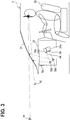
- the HUD 50 is installed in an instrument panel 22 inside the cabin 2a illustrated in FIGs. 1 and 3 .
- the HUD 50 forms a display image 56 which represents predetermined information by a projector 50a of a liquid crystal type or a scanning type.
- the HUD 50 projects the display image 56 formed in this manner on a front windshield 21 as a "projection member" in the subject vehicle 2 through an optical system 50b such as a concave mirror.
- the front windshield 21 is formed of a light-transmissive glass so as to transmit a front scenery 8 which is present ahead of the subject vehicle 2 outside the cabin 2a.
- a beam of the display image 56 reflected by the front windshield 21 and a beam from the front scenery 8 transmitted through the front windshield 21 are perceived by the user on the driver's seat 20.
- a virtual image of the display image 56 which is formed at a position ahead of the front windshield 21 is displayed in a superimposed manner on a part of the front scenery 8 as illustrated in FIG. 1 , so that the virtual image is visually recognizable by the user on the driver's seat 20.
- two kinds of areas A1 and A2 are set in a display area as a range in which the display image 56 is virtually displayed.
- the first display area A1 is set for superimposing the display image 56, which is virtually displayed, in association with a specific object in the front scenery 8.
- the first display area A1 for the association is adjusted by the HUD 50 so that the display image 56 is formed at a far position which is, for example, approximately 15 m away forward from the subject vehicle 2 in the front scenery 8.
- the second display area A2 is set for virtually displaying the display image 56 whose association with a specific object in the front scenery 8 is eliminated.
- the second display area A2 for the elimination of association is adjusted to a smaller size than the first display area A1 below the first display area A1 by the HUD 50 so that the display image 56 is formed at a close distance position which is, for example, approximately 2 m away forward from the subject vehicle 2 in the front scenery 8. That is, the display image 56 virtually displayed in the second display area A2 is formed at the position that is closer to the subject vehicle 2 than the position of the display image 56 in the first display area A1 is.
- the projector 50a and the optical system 50b which constitute the HUD 50 may be disposed for each of the display areas A1 and A2 as illustrated in FIG. 3 , or either the projector 50a or the optical system 50b may be disposed commonly to the display areas A1 and A2 (not illustrated).
- a display image 56 having no such association may be virtually displayed in the first display area A1.
- a display image 56 having such association may be virtually displayed in the second display area A2.
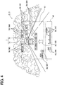
- the multiple types of display images 56 include at least a following distance image 560, an exit distance image 561, a road surface image 562, a weather image 563, a temperature image 564, a navigation image 565, a vehicle speed image 566, and an engine speed image 567.
- the following distance image 560 is virtually displayed in association with a different vehicle as an obstacle ahead in the first display area A1.
- the following distance image 560 represents following distance information with the nearest vehicle which travels ahead of the subject vehicle 2 among pieces of the obstacle information as the traffic information.
- a standard display state as illustrated in FIG. 4 and a simple display state having a limited display amount compared to a display amount in the standard display state as illustrated in FIGs. 5 and 6 are set.
- the following distance image 560 in the standard display state includes a numeral and a character which indicate a value and a unit of the following distance, respectively, a character which indicates contents meant by the numeral, and a figure which indicates the nearest vehicle which is a target of the numeral.
- the display amount of the following distance image 560 in the simple display state is reduced by omitting the character indicating the contents.
- the exit distance image 561 is virtually displayed in association with the exit 7b of the tunnel 7 in the first display area A1.
- the exit distance image 561 represents arrival distance information to the nearest exit 7b to which the subject vehicle 2 heads among pieces of the tunnel information.
- a standard display state as illustrated in FIG. 4 and a simple display state having a limited display amount compared to a display amount in the standard display state as illustrated in FIGs. 5 and 6 are set.
- the exit distance image 561 in the standard display state includes a numeral and a character which indicate a value and a unit of the arrival distance, respectively, a character which indicates contents meant by the numeral, a figure which indicates the exit 7b which is a target of the numeral.
- the display amount of the exit distance image 561 in the simple display state is reduced by omitting the character indicating the contents.
- the road surface image 562 is virtually displayed in association with a traveling road ahead of the subject vehicle 2 in the first display area A1.
- the road surface image 562 represents road surface information relating to the traveling road ahead of the subject vehicle 2 among pieces of the traveling road information.
- a standard display state as illustrated in FIG. 4 and a simple display state having a limited display amount compared to a display amount in the standard display state as illustrated in FIG. 7 are set.
- the road surface image 562 in the standard display state includes a figure which schematically indicates a road surface state and a character which indicates contents meant by the figure.
- the display amount of the road surface image 562 in the simple display state is reduced by omitting the character indicating the contents.
- the weather image 563 is virtually displayed in association with a sky area ahead and above the subject vehicle 2 in the first display area A1.
- the weather image 563 represents weather information relating to a traveling environment of the subject vehicle 2 among pieces of the meteorological information.
- a standard display state as illustrated in FIG. 4 and a simple display state having a limited display amount compared to a display amount in the standard display state as illustrated in FIG. 7 are set.
- the weather image 563 in the standard display state includes a figure which schematically indicates a weather condition and a character which indicates contents meant by the figure.
- the display amount of the weather image 563 in the simple display state is reduced by omitting the character indicating the contents.
- the temperature image 564 is virtually displayed in association with a sky area ahead and above the subject vehicle 2 in the first display area A1.
- the temperature image 564 represents temperature information relating to the traveling environment of the subject vehicle 2 among pieces of the meteorological information.
- a standard display state as illustrated in FIG. 4 and a simple display state having a limited display amount compared to a display amount in the standard display state as illustrated in FIG. 7 are set.
- the temperature image 564 in the standard display state includes a numeral and a character which indicate a value and a unit of the outside temperature, respectively, and a character which indicates contents meant by the numeral.
- the display amount of the temperature image 564 in the simple display state is reduced by omitting the character indicating the contents.
- the navigation image 565 is virtually displayed in association with the traveling road ahead of the subject vehicle 2 in the first display area A1.
- the navigation image 565 represents navigation information for guiding a traveling route of the subject vehicle 2.
- the navigation image 565 includes at least a figure which indicates a planned traveling route of the subject vehicle 2 among pieces of the navigation information.
- the navigation information can be acquired in the HCU 54, which is described in detail below, on the basis of map information stored in a memory 54b and an output signal of the vehicle state sensor 40.
- the vehicle speed image 566 is virtually displayed at a fixed position which is not associated with a specific object in the second display area A2.
- the vehicle speed image 566 represents vehicle speed information based on an output signal of the vehicle speed sensor of the vehicle state sensor 40.
- the vehicle speed image 566 includes a numeral and a character which indicate a value and a unit of the vehicle speed, respectively.
- the engine speed image 567 is virtually displayed beside the vehicle speed image 566 at a fixed position which is not associated with a specific object in the second display area A2.
- the engine speed image 567 represents engine speed information based on an output signal of the engine speed sensor of the vehicle state sensor 40.
- the engine speed image 567 includes a numeral and a character which indicate a value and a unit of the engine speed, respectively.
- the display image 56 for example, an image related to music information or video information provided inside the cabin 2a of the subject vehicle 2 may be employed in addition to the above images 560, 561, 562, 563, 564, 565, 566, and 567. Further, virtual image display can be achieved also by projecting the display image 56 on a light-transmissive combiner which is disposed on the instrument panel 22 to transmit the front scenery 8 in cooperation with the front windshield 21.
- the MFD 51 is installed in a center console 23 inside the cabin 2a illustrated in FIG. 1 .
- the MFD 51 displays a real image of an image which is formed to represent predetermined information in one or more liquid crystal panels visually recognizably by the user on the driver's seat 20.
- As the real image display by the MFD 51 display of an image representing one or more of the followings: the navigation information; the music information; and the video information is employed.
- the combination meter 52 is installed in the instrument panel 22 inside the cabin 2a.
- the combination meter 52 displays vehicle information relating to the subject vehicle 2 visually recognizably by the user on the driver's seat 20.
- the combination meter 52 is a digital meter which displays vehicle information by an image formed on a liquid crystal panel or an analog meter which displays vehicle information by indicating a scale number by an indicator.
- display by the combination meter 52 for example, display representing one or more of the following pieces of information: the vehicle speed; the engine speed; the fuel remaining amount; the cooling water temperature; and information of the turn switch and the automatic control switch is employed.
- the HCU 54 is mainly composed of a microcomputer which includes a processor 54a and the memory 54b.
- the HCU 54 is connected to the display elements 50, 51, and 52 of the display system 5 and the in-vehicle network 6.
- the HCU 54 synchronously controls the operations of the display elements 50, 51, and 52.
- the HCU 54 executes the control of these operations in accordance with, for example, acquired information or output signals of the surroundings monitoring ECU 31 and the sensors 40 and 41, control information of the vehicle control ECU 42, stored information of the memory 54b, and acquired information of the HCU 54 itself.
- Each of the memory 54b of the HCU 54 and memories of the other various ECUs includes one or more storage media such as a semiconductor memory, a magnetic medium, and an optical medium.
- the HCU 54 of the present embodiment functions as a "vehicular display control apparatus" so as to read the display image 56 which is stored in the memory 54b as data and virtually display the read display image 56 on the HUD 50.
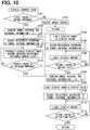
- the HCU 54 executes a display control program by the processor 54a to functionally implement each step of a display control flow illustrated in FIG. 8 .
- the display control flow is started in response to an ON operation of the power switch as the occupant sensor 41 and ended in response to an OFF operation of the power switch.
- “S" refers to each step.
- An image storage unit which stores the display image 56 which is necessary in the display control flow may be implemented by any of memories of built-in ECUs of the display elements 50, 51, and 52 or cooperation of multiple memories selected from the memories of the built-in ECUs of the display elements 50, 51, and 52 and the memory 54b of the HCU 54.
- the timing of starting the execution of S101 is a first timing T1 when the traveling position of the subject vehicle 2 is before the entrance 7a of the tunnel 7.
- the first timing T1 is adjusted to a timing when the traveling position of the subject vehicle 2 reaches a position before the entrance 7a by a set distance L1.
- the set distance L1 which defines the first timing T1 is variably set so as to secure the safety of the subject vehicle 2 on the basis of one or more of the followings: the vehicle speed information of the subject vehicle 2; the traffic information; the tunnel information; the traveling road information; and the meteorological information.
- the set distance L1 is set to 100 m when the subject vehicle 2 travels on an ordinary road where a legally permitted maximum speed is a predetermined speed or set to 200 m when the subject vehicle 2 travels on an expressway where a legally permitted maximum speed is higher than that in the ordinary road.
- the process shifts to S102.
- Normal control of virtual image display in each of the display areas A1 and A2 is executed in S102, and the process then returns to S101.
- the following distance image 560, the exit distance image 561, the road surface image 562, the weather image 563, the temperature image 564, and the navigation image 565 are virtually displayed as the display image 56 in the first display area A1 as illustrated in FIG. 4 .
- the following distance image 560 and the road surface image 562 are displayed in bright red
- the weather image 563 and the temperature image 564 are displayed in bright yellow
- the navigation image 565 are displayed in bright blue.
- the vehicle speed image 566 and the engine speed image 567 are virtually displayed as the display image 56 in the second display area A2. At this time, for example, the vehicle speed image 566 and the engine speed image 567 are displayed in white.
- the brightness of each of the images 560, 561, 562, 563, 564, 565, 566, and 567 can be adjusted, for example, by RGB gradation values in the projector 50a or light emission luminance values of a light source in the projector 50a.
- Virtual image display of the exit distance image 561 is started when the subject vehicle 2 passes a traveling position that is away from the entrance 7a of the tunnel 7 by a predetermined distance that is longer than the set distance L1 outside the tunnel 7.
- each piece of information Ii, Io as the tunnel internal and external information I is acquired from the outside through the wireless communication device 40a.
- at least illuminance information, traffic information, traveling road information, and tunnel information relating to an internal condition of the tunnel 7 ahead are acquired as the tunnel internal information li.
- at least illuminance information, traffic information, traveling road information, and meteorological information relating to an external condition before the tunnel 7 ahead are acquired as the tunnel external information lo.
- provision information which is provided to the user inside the tunnel 7 is limited to the tunnel internal information li among pieces of the tunnel internal and external information I acquired in S103.
- a display range and a display color are limited.
- the provision information to the user is limited to following distance information and arrival distance information which are represented by the following distance image 560 and the exit distance image 561, respectively, in the first display area A1 as the tunnel internal information li necessary for driving of the subject vehicle 2.
- information represented by the road surface image 562, the weather image 563, the temperature image 564, and the navigation image 565 in the first display area A1 and information represented by the vehicle speed image 566 and the engine speed image 567 in the second display area A2 are not provided to the user.
- the timing of starting the execution of S104 can be regarded as the first timing T1 before the entrance 7a of the tunnel 7.
- the provision information in the first display area A1 is limited to the following distance information and the arrival distance information substantially from the first timing T1 to a second timing T2 (described below), that is, from the position before the entrance 7a outside the tunnel 7 to a position before the exit 7b inside the tunnel 7.
- the limiting process described above also limits the display range of the display image 56 only to the first display area A1 and limits the display color of the display image 56 to the display color of the following distance image 560 and the exit distance image 561 (e.g., red similar to the color during normal control).
- the brightness of the display image 56 which represents the tunnel internal information li limited in S104 is adjusted according to the tunnel internal information li acquired in S103. Specifically, the brightness of the following distance image 560 and the exit distance image 561 which represent the following distance information and the arrival distance information, respectively, as the limited tunnel internal information li is adjusted to a brightness according to illuminance information inside the tunnel 7 ahead among pieces of the tunnel internal information li. At this time, in particular, the brightness of the following distance image 560 and the exit distance image 561 is adjusted to a brightness darker than the brightness in the normal control in S102 according to the illuminance information inside the tunnel 7 ahead. As a result, in the present embodiment, for example, the display color of the following distance image 560 and the exit distance image 561 is set to dark red.
- the timing of starting the execution of S105 can be also regarded as the first timing T1 before the entrance 7a of the tunnel 7.
- the brightness of the images 560 and 561 displayed in the first display area A1 is adjusted according to the illuminance information substantially from the first timing T1 to the second timing T2 (described below), that is, from the position before the entrance 7a outside the tunnel 7 to the position before the exit 7b inside the tunnel 7.
- the first timing T1 corresponds to an "entrance adjustment timing".
- the brightness of each of the images 560 and 561 can be adjusted by RGB gradation values in the projector 50a or light emission luminance values of the light source in the projector 50a.
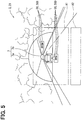
- the HUD 50 virtually displays the display image 56 having the information li limited in S104 and the brightness adjusted in S105. Specifically, both of the following distance image 560 and the exit distance image 561 having a reduced brightness compared to the brightness in the normal control in S102 are virtually displayed in a simple display state in the first display area A1 as illustrated in FIGs. 5 and 6 . In other words, the display amount is limited.
- the virtual image display of the road surface image 562, the weather image 563, the temperature image 564, and the navigation image 565 in the first display area A1 and the virtual image display of the vehicle speed image 566 and the engine speed image 567 in the second display area A2 disappear.
- the timing of starting the execution of S106 can be also regarded as the first timing T1 before the entrance 7a of the tunnel 7.
- the display amount by the display image 56 in the first display area A1 is limited to a display amount by the images 560 and 561 in the simple display state substantially from the first timing T1 to the second timing T2 (described below), that is, from the position before the entrance 7a outside the tunnel 7 to the position before the exit 7b inside the tunnel 7.
- FIG. 5 illustrates a display state from the first timing T1 to the timing when the subject vehicle 2 enters the entrance 7a of the tunnel 7 outside the tunnel 7.
- FIG. 6 illustrates a display state from the timing when the subject vehicle 2 enters the entrance 7a of the tunnel 7 to the second timing T2 inside the tunnel 7.
- the first timing T1 corresponds also to an "entrance limitation timing".
- the process shifts to S107.
- S107 it is determined whether the timing of starting the execution of S107 is the second timing T2 when the traveling position of the subject vehicle 2 is before the exit 7b of the tunnel 7.
- the second timing T2 is adjusted to a timing when the traveling position of the subject vehicle 2 reaches a position before the exit 7b by a set distance L2.
- the set distance L2 which defines the second timing T2 is variably set in a manner similar to the set distance L1.
- the set distance L2 is set to 100 m when the subject vehicle 2 travels on an ordinary road where a legally permitted maximum speed is a predetermined speed or set to 200 m when the subject vehicle 2 travels on an expressway where a legally permitted maximum speed is higher than that in the ordinary road.
- provision information which is provided to the user before the exit 7b of the tunnel 7 is limited to the tunnel external information Io among pieces of the tunnel internal and external information I acquired in S108.
- the display range and the display color are limited.
- the provision information to the user is limited to road surface information, weather information, and temperature information which are represented by the road surface image 562, the weather image 563, and the temperature image 564, respectively, in the first display area A1 as the tunnel external information Io necessary for driving of the subject vehicle 2.
- information represented by the following distance image 560, the exit distance image 561, and the navigation image 565 in the first display area A1 and information represented by the vehicle speed image 566 and the engine speed image 567 in the second display area A2 are not provided to the user.
- the timing of starting the execution of S109 can be regarded as the second timing T2 before the exit 7b of the tunnel 7.
- the provision information in the first display area A1 is limited to the road surface information, the weather information, and the temperature information substantially from the second timing T2 to a third timing T3 (described below), that is, from the position before the exit 7b inside the tunnel 7 to an exit from the exit 7b.
- the limiting process described above also limits the display range of the display image 56 only to the first display area A1 and limits the display color of the display image 56 to the display color of the road surface information, the weather information, and the temperature information (e.g., yellow similar to the color during normal control).
- the brightness of the display image 56 which represents the tunnel external information Io limited in S109 is adjusted according to the tunnel external information Io acquired in S108.
- the brightness of the road surface image 562, the weather image 563, and the temperature image 564 which represent the road surface information, the weather information, and the temperature information, respectively, as the limited tunnel external information Io is adjusted to a brightness according to illuminance information and meteorological information outside the exit 7b ahead among pieces of the tunnel external information lo.
- the brightness of the road surface image 562, the weather image 563, and the temperature image 564 is adjusted to a brightness higher than the brightness in the adjustment in S105 according to the illuminance information and the meteorological information outside the exit 7b ahead.
- the display color of the road surface image 562, the weather image 563, and the temperature image 564 is set to bright yellow.
- the timing of starting the execution of S110 can be also regarded as the second timing T2 before the exit 7b of the tunnel 7.
- the brightness of the images 562, 563, and 564 displayed in the first display area A1 is adjusted according to the illuminance information and the meteorological information substantially from the second timing T2 to the third timing T3 (described below), that is, from the position before the exit 7b inside the tunnel 7 to an exit from the exit 7b.
- the second timing T2 corresponds to an "exit adjustment timing".
- the brightness of each of the images 562, 563, and 564 can be adjusted by RGB gradation values in the projector 50a or light emission luminance values of the light source in the projector 50a.
- the HUD 50 virtually displays the display image 56 having the information Io limited in S109 and the brightness adjusted in S110. Specifically, all of the road surface image 562, the weather image 563, and the temperature image 564 having an increased brightness compared to the brightness in the adjustment in S105 are virtually displayed in a simple display state in the first display area A1 as illustrated in FIG. 7 . In other words, the display amount is limited.
- the virtual image display of the following distance image 560, the exit distance image 561, and the navigation image 565 in the first display area A1 and the virtual image display of the vehicle speed image 566 and the engine speed image 567 in the second display area A2 disappear.
- the timing of starting the execution of S111 can be also regarded as the second timing T2 before the exit 7b of the tunnel 7.
- the display amount by the display image 56 in the first display area A1 is limited to a display amount by the images 562, 563, and 564 in the simple display state substantially from the second timing T2 to the third timing T3 (described below), that is, from the position before the exit 7b inside the tunnel 7 to an exit from the exit 7b.
- the second timing T2 corresponds also to an "exit limitation timing".
- the process shifts to S112.
- S112 it is determined whether the timing of starting the execution of S112 is the third timing T3 when the subject vehicle 2 makes an exit from the exit 7b of the tunnel 7. As a result, the process returns to S111 when a negative determination is made and, on the other hand, returns to S101 when an affirmative determination is made.
- a function part that executes S103 and S108 corresponds to an "information acquisition unit”
- a function part that executes S105 and S110 corresponds to an "adjustment unit”
- a function part that executes S104, S106, S109, and S111 corresponds to a "limitation unit”.
- the brightness of the display image 56 is adjusted according to the tunnel internal information li acquired by the HCU 54 at the first timing T1 before the entrance 7a of the tunnel 7.
- the tunnel internal information li which indicates an internal condition of the tunnel 7 is transmitted from the outside of the subject vehicle 2 and acquired by wireless communication.
- the internal condition immediately before an entry of the subject vehicle 2 into the entrance 7a can be timely and accurately reflected in the tunnel internal information li.
- the adjustment according to the timely and accurate tunnel internal information li makes it possible to virtually display the display image 56 having a brightness that enables visual recognition readability to be ensured against the front scenery 8 serving as a background of the display in the subject vehicle 2 with the entry into the entrance 7a.
- the brightness of the display image 56 is adjusted according to the illuminance information inside the tunnel 7 among pieces of the tunnel internal information li acquired by the HCU 54.
- the illuminance information is transmitted from the outside of the subject vehicle 2 and acquired by wireless communication as the tunnel internal information li which indicates an internal condition of the tunnel 7.
- the external illuminance inside the tunnel 7 immediately before an entry into the entrance 7a can be timely and accurately reflected in the illuminance information.
- the adjustment according to the timely and accurate illuminance information makes it possible to virtually display the display image 56 having a brightness that enables visual recognition readability to be ensured against the external illuminance inside the tunnel 7 with the entry into the entrance 7a.
- the brightness of the display image 56 in the first display area A1 is adjusted. Accordingly, it is possible to preferentially adjust the brightness of the display image 56 which can be easily closely observed by the user due to the association with the specific object. Thus, the visual recognition readability against the front scenery 8 can be ensured with the entry into the entrance 7a.
- the brightness of the display image 56 is adjusted according to the tunnel external information Io acquired by the HCU 54 at the second timing T2 before the exit 7b of the tunnel 7.
- the tunnel external information Io which indicates an external condition of the tunnel 7 is transmitted from the outside of the subject vehicle 2 and acquired by wireless communication.
- the external condition immediately before an exit of the subject vehicle 2 from the exit 7b can be timely and accurately reflected in the tunnel external information lo.
- the adjustment according to the timely and accurate tunnel external information Io makes it possible to virtually display the display image 56 having a brightness that enables visual recognition readability to be ensured against the front scenery 8 serving as a background of the display in the subject vehicle 2 with the exit from the exit 7b.
- the brightness of the display image 56 is adjusted according to the illuminance information outside the tunnel 7 among pieces of the tunnel external information Io acquired by the HCU 54.
- the illuminance information is transmitted from the outside of the subject vehicle 2 and acquired by wireless communication as the tunnel external information Io which indicates an external condition of the tunnel 7.
- the tunnel external information Io which indicates an external condition of the tunnel 7.
- the adjustment according to the timely and accurate illuminance information makes it possible to virtually display the display image 56 having a brightness that enables visual recognition readability to be ensured against the external illuminance outside the tunnel 7 with the exit from the exit 7b.
- the brightness of the display image 56 is adjusted according to the meteorological information outside the tunnel 7 among pieces of the tunnel external information Io acquired by the HCU 54.
- the meteorological information is transmitted from the outside of the subject vehicle 2 and acquired by wireless communication as the tunnel external information Io which indicates an external condition of the tunnel 7.
- the tunnel external information Io which indicates an external condition of the tunnel 7.
- the adjustment according to the timely and accurate meteorological information makes it possible to virtually display the display image 56 having a brightness that enables visual recognition readability to be ensured against the meteorological condition outside the tunnel 7 with the exit from the exit 7b.
- the brightness of the display image 56 in the first display area A1 is adjusted. Accordingly, it is possible to preferentially adjust the brightness of the display image 56 which can be easily closely observed by the user due to the association with the specific object. Thus, the visual recognition readability against the front scenery 8 can be ensured with the exit from the exit 7b.
- the provision information by the display image 56 is limited to the tunnel internal information li among pieces of the tunnel internal and external information I acquired by the HCU 54.
- the tunnel internal information li which indicates an internal condition of the tunnel 7 is transmitted from the outside of the subject vehicle 2 and acquired by wireless communication as the tunnel internal and external information I which indicates internal and external conditions of the tunnel 7.
- the internal condition during traveling of the subject vehicle 2 can be timely and accurately reflected in the tunnel internal information li.
- the timely and accurate limitation of information type makes it possible to limit the amount of provision information to an information amount that enables visual recognition readability to be ensured against the front scenery 8 serving as a background of the display in the subject vehicle 2 and virtually display the display image 56 which represents the provision information during traveling inside the tunnel 7.
- the provision information by the display image 56 is limited to the tunnel internal information li necessary for driving of the subject vehicle 2 among pieces of the tunnel internal and external information acquired by the HCU 54. Accordingly, it is possible to provide the tunnel internal information li limited to an information amount necessary for driving of the subject vehicle 2 inside the tunnel 7 where it is hardly acceptable for the user to look aside. Thus, it is possible to ensure the visual recognition readability of the display image 56 against the front scenery 8 while giving the user a sense of security during traveling inside the tunnel 7.
- the limitation to the tunnel internal information li is started from the first timing T1 before the entrance 7a of the tunnel 7. Accordingly, the provision information by the display image 56 can be reliably limited to the tunnel internal information li from an entry of the subject vehicle 2 into the entrance 7a inside the tunnel 7. Thus, it is possible to ensure the visual recognition readability against the front scenery 8.
- the display image 56 is limited to the tunnel internal information li, but also the display color of the display image 56 which represents the tunnel internal information li is limited inside the tunnel 7 of the present embodiment. According to the information limitation and the display color limitation, the visual recognition readability which is necessary during traveling inside the tunnel 7 where it is hardly acceptable for the user to look aside can be reliably ensured against the front scenery 8.
- the display image 56 is limited to the tunnel internal information li, but also the display range of the display image 56 which represents the tunnel internal information li is limited. According to the information limitation and the display range limitation, the visual recognition readability which is necessary during traveling inside the tunnel 7 where it is hardly acceptable for the user to look aside can be reliably ensured against the front scenery 8.
- the display image 56 is limited to the tunnel internal information li, but also the display amount of the display image 56 which represents the tunnel internal information li is limited. According to the information limitation and the display amount limitation, the visual recognition readability which is necessary during traveling inside the tunnel 7 where it is hardly acceptable for the user to look aside can be reliably ensured against the front scenery 8.
- the provision information in the first display area A1 is limited to the tunnel internal information li. Accordingly, it is possible to preferentially reduce the amount of provision information by the display image 56 which can be easily closely observed by the user due to the association with the specific object. Thus, the visual recognition readability against the front scenery 8 can be ensured during traveling inside the tunnel 7.
- the provision information by the display image 56 is limited to the tunnel external information Io instead of the tunnel internal information li among pieces of the tunnel internal and external information I acquired by the HCU 54 at the second timing T2 before the exit 7b of the tunnel 7.
- the tunnel external information lo which indicates an external condition of the tunnel 7 is transmitted from the outside of the subject vehicle 2 and acquired by wireless communication as the tunnel internal and external information I which indicates internal and external conditions of the tunnel 7.
- the external condition immediately before an exit from the exit 7b can be timely and accurately reflected in the tunnel external information lo.
- the timely and accurate limitation of information type makes it possible to limit the amount of provision information to an information amount that enables visual recognition readability to be ensured against the front scenery 8 serving as a background of the display in the subject vehicle 2 and virtually display the display image 56 which represents the provision information with the exit from the exit 7b.
- the provision information by the display image 56 is limited to the tunnel external information lo necessary for driving of the subject vehicle 2 among pieces of the tunnel internal and external information I acquired by the HCU 54. Accordingly, it is possible to provide the tunnel external information lo limited to an information amount necessary for driving of the subject vehicle 2 immediately before an exit from the exit 7b where it is hardly acceptable for the user to look aside. Thus, it is possible to ensure the visual recognition readability of the display image 56 against the front scenery 8 while giving the user a sense of security with the exit from the exit 7b.
- the display color, the display range, and the display amount of the display image 56 which represents the tunnel external information Io are limited in a manner similar to the processes inside the tunnel 7 described above.
- the visual recognition readability which is necessary in an exit from the exit 7b where it is hardly acceptable for the user to look aside can be reliably ensured against the front scenery 8.
- the provision information in the first display area A1 is limited to tunnel external information lo. Accordingly, it is possible to preferentially reduce the amount of provision information by the display image 56 which can be easily closely observed by the user due to the association with the specific object. Thus, the visual recognition readability against the front scenery 8 can be ensured with an exit from the exit 7b.
- the vehicle driving assistance system 1 which includes the HCU 54 of the present embodiment, it is possible to ensure the visual recognition readability of the display image 56, which is virtually displayed, against the front scenery 8 inside and outside the tunnel 7, the front scenery 8 serving as a background of the display.
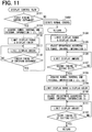
- virtual image display similar to the virtual image display in the normal control in S102 may be executed except that the brightness of each of the images 560, 561, 562, 563, 564, 565, 566, and 567 is adjusted in a manner similar to S105 by sequentially shifting to S113 and S114 from S103.
- S115 following S114 it is determined whether the timing of starting the execution of S115 is a fourth timing T4 when the subject vehicle 2 enters the entrance 7a of the tunnel 7.
- the process returns to S114 when a negative determination is made and, on the other hand, shifts to S104 when an affirmative determination is made.
- limitation and virtual image display similar to S104 and S106 may be executed with a brightness similar to the brightness in the normal control in S102 by sequentially shifting to S116 and S117 from S103.
- S118 following S117 it is determined whether the timing of starting the execution of S118 is the fourth timing T4 when the subject vehicle 2 enters the entrance 7a of the tunnel 7.
- the process returns to S117 when a negative determination is made and, on the other hand, shifts to S104 when an affirmative determination is made.
- S116 corresponds to limiting the display range and the display color.
- S117 corresponds to limiting the display amount.
- S119 may be executed instead of S101 to determine whether the timing of starting the execution of S119 is the fourth timing T4 when the subject vehicle 2 enters the entrance 7a of the tunnel 7.
- the process shifts to S102 when a negative determination is made and, on the other hand, shifts to S103 when an affirmative determination is made.
- virtual image display similar to the virtual image display in the normal control in S102 may be executed except that the brightness of each of the images 560, 561, 562, 563, 564, 565, 566, and 567 is adjusted in a manner similar to S110 by sequentially shifting to S120 and S121 from S108.
- S122 following S121 it is determined whether the timing of starting the execution of S122 is the third timing T3 when the subject vehicle 2 makes an exit from the exit 7b of the tunnel 7. As a result, the process returns to S121 when a negative determination is made and, on the other hand, returns to S101 when an affirmative determination is made.
- limitation and virtual image display similar to S109 and S111 may be executed with a brightness similar to the brightness in the adjustment in S105 by sequentially shifting to S123 and S124 from S108.
- S125 following S124 it is determined whether the timing of starting the execution of S125 is the third timing T3 when the subject vehicle 2 makes an exit from the exit 7b of the tunnel 7.
- the process returns to S124 when a negative determination is made and, on the other hand, returns to S101 when an affirmative determination is made.
- S123 corresponds to limiting the display range and the display color
- S124 corresponds to limiting the display amount.
- S126 may be executed instead of S107 to determine whether the timing of starting the execution of S126 is the third timing T3 when the subject vehicle 2 makes an exit from the exit 7b of the tunnel 7. As a result, the process returns to S106 when a negative determination is made and, on the other hand, shifts to S101 when an affirmative determination is made.
- any one of the first to third modifications may be combined with any one of the fourth to sixth modifications.
- FIG. 16 illustrates a seventh modification that combines the first modification with the fourth modification.
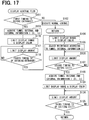
- FIG. 17 illustrates a seventh modification that combines the second modification with the fifth modification.
- an eighth modification as illustrated in FIG. 18 , in the images 560, 561, and 564 in a simple display state, a character which indicates a unit in a standard display state may be omitted in addition to or instead of a character which indicates the contents in the standard display state.
- the brightness adjustment in S105 may be executed according to, for example, traveling road information (specifically, a road surface condition) or external light information (specifically, a solar radiation direction) in addition to or instead of illuminance information.
- the brightness adjustment in S110 may be executed according to, for example, traveling road information (specifically, a road surface condition) or external light information (specifically, a solar radiation direction) in addition to or instead of at least either illuminance information or meteorological information.
- congestion information may be employed as provision information limited in S104 of an eleventh modification as long as the congestion information is tunnel internal information li necessary for driving of the subject vehicle 2.
- Information other than the road surface information, weather information, and temperature information, for example, following distance information or congestion information may be employed as provision information limited in S109 of a twelfth modification as long as the following distance information or the congestion information is tunnel external information Io necessary for driving of the subject vehicle 2.
- Information (e.g., a vehicle type as obstacle information) unnecessary for driving of the subject vehicle 2 may be employed as provision information of a thirteenth modification in addition to or instead of information necessary for the driving as long as the provision information is limited to tunnel internal information li in S104.
- Information (e.g., a vehicle type as obstacle information) unnecessary for driving of the subject vehicle 2 may be employed as provision information of a fourteenth modification in addition to or instead of information necessary for the driving as long as the provision information is limited to tunnel external information Io in S109.
- the display image 56 which represents the employed provision information is virtually displayed in S106 or S111.
- provision information in each of the display areas A1 and A2 during normal control may not be limited in S104, but may all be employed so that, of the display color and the display range of the display image 56, at least the latter is not limited.
- provision information in each of the display areas A1 and A2 during normal control may not be limited in S109, but may all be employed so that, of the display color and the display range of the display image 56, at least the latter is not limited.
- the display image 56 which represents the employed provision information is virtually displayed in S106 or S111.
- a standard display state may be employed in S106 so as not to limit the display amount of the display image 56.
- a standard display state may be employed in S111 so as not to limit the display amount of the display image 56.
- At least one type of provision information in the second display area A2 during normal control may not be limited, but may be employed in S104, and the brightness of the provision information in the second display area A2 may be adjusted in S105 in a manner similar to provision information in the first display area A1.
- at least one type of provision information in the second display area A2 during normal control may not be limited, but may be employed in S109, and the brightness of the provision information in the second display area A2 may be adjusted in S110 in a manner similar to provision information in the first display area A1.
- the display image 56 which represents the employed provision information is virtually displayed in S106 or S111.
- virtual image display of the display image 56 in the second display area A2 may not be employed.
- the display image 56 having information and brightness limited and adjusted by the display control flow may be virtually displayed in the second display area A2 instead of the first display area A1.
- virtual image display of the display image 56 in the first display area A1 may not be employed further in the twenty-second modification.
- At least some of the steps of the display control flow may be implemented as hardware by one or more ICs instead of being functionally implemented by the HCU 54.
- the surroundings monitoring ECU 31; and the display control ECUs of the display elements 50, 51, and 52 may function as the "vehicular display control apparatus".
- a flowchart or the processing of the flowchart in the present application includes multiple steps (also referred to as sections), each of which is represented, for instance, as S101. Further, each step can be divided into several sub-steps while several steps can be combined into a single step.
Landscapes
- Engineering & Computer Science (AREA)
- Mechanical Engineering (AREA)
- Transportation (AREA)
- Combustion & Propulsion (AREA)
- Chemical & Material Sciences (AREA)
- General Physics & Mathematics (AREA)
- Multimedia (AREA)
- Theoretical Computer Science (AREA)
- Physics & Mathematics (AREA)
- Signal Processing (AREA)
- Computer Hardware Design (AREA)
- Instrument Panels (AREA)
- Transforming Electric Information Into Light Information (AREA)
- Testing, Inspecting, Measuring Of Stereoscopic Televisions And Televisions (AREA)
Abstract
Description
- The present application is based on Japanese Patent Application No.
2016-158319 filed on August 11, 2016 - The present disclosure relates to a vehicular display control apparatus and a vehicle driving assistance system including the same.
- There has been conventionally known a head-up display (referred to as an HUD) that projects a display image on a projection member that transmits a front scenery in a subject vehicle to virtually display the display image visually recognizably by a user. Such an HUD is widely used, for example, in a vehicle driving assistance system that assists driving of a subject vehicle by a user.
-
Patent Literature 1 discloses a vehicular display control technique that changes the brightness of a display image on the basis of tunnel information before passage through an entrance or an exit of a tunnel to control virtual image display by an HUD. Positional information and shape information relating to the entrance or the exit of the tunnel are employed as the tunnel information. - Patent Literature 1:
JP 2015-127170 A - However, in the technique disclosed in
Patent Literature 1, the tunnel information is mere map data which is stored in a navigation apparatus or a server apparatus which is communicable with the subject vehicle. Thus, it is assumed that the tunnel information does not timely and accurately reflect internal and external conditions of the tunnel. A display image which is virtually displayed on the basis of such tunnel information which is neither timely nor accurate may cause reduction in readability by visual recognition (hereinbelow, referred to as "visual recognition readability") against a front scenery serving as a background of the display in the subject vehicle. - It is an object of the present disclosure to provide a vehicular display control apparatus and a vehicle driving assistance system that ensure the visual recognition readability of a virtually displayed display image against a front scenery inside and outside a tunnel, the front scenery serving as a background of the display in a subject vehicle.
- A first disclosure of the present disclosure provides a vehicular display control apparatus that, in a subject vehicle equipped with a head-up display that projects a display image on a projection member that transmits a front scenery to virtually display the display image visually recognizably by a user, controls the virtual image display. The vehicular display control apparatus includes an information acquisition unit that acquires tunnel internal information that is transmitted from outside of the subject vehicle by wireless communication and indicates an internal condition of a tunnel, and an adjustment unit that adjusts a brightness of the display image according to the tunnel internal information acquired by the information acquisition unit at an entrance adjustment timing before an entrance of the tunnel.
- According to the first disclosure as described above, the brightness of the display image is adjusted according to the tunnel internal information acquired by the information acquisition unit at the entrance adjustment timing before the entrance of the tunnel. The tunnel internal information which indicates an internal condition of the tunnel is transmitted from the outside of the subject vehicle and acquired by wireless communication. Thus, the internal condition immediately before an entry of the subject vehicle into the entrance of the tunnel can be timely and accurately reflected in the tunnel internal information. Thus, the adjustment according to the timely and accurate tunnel internal information makes it possible to virtually display the display image having a brightness that enables visual recognition readability to be ensured against the front scenery serving as a background of the display in the subject vehicle with the entry into the entrance of the tunnel.
- A second disclosure of the present disclosure provides a vehicular display control apparatus that, in a subject vehicle equipped with a head-up display that projects a display image on a projection member that transmits a front scenery to virtually display the display image visually recognizably by a user, controls the virtual image display. The vehicular display control apparatus includes an information acquisition unit that acquires tunnel external information that is transmitted from outside of the subject vehicle by wireless communication and indicates an external condition of a tunnel, and an adjustment unit that adjusts a brightness of the display image according to the tunnel external information acquired by the information acquisition unit at an exit adjustment timing before an exit of the tunnel.
- According to the second disclosure as described above, the brightness of the display image is adjusted according to the tunnel external information acquired by the information acquisition unit at the exit adjustment timing before the exit of the tunnel. The tunnel external information which indicates an external condition of the tunnel is transmitted from the outside of the subject vehicle and acquired by wireless communication. Thus, the external condition immediately before an exit of the subject vehicle from the exit of the tunnel can be timely and accurately reflected in the tunnel external information. Thus, the adjustment according to the timely and accurate tunnel external information makes it possible to virtually display the display image having a brightness that enables visual recognition readability to be ensured against the front scenery serving as a background of the display in the subject vehicle with the exit of the subject vehicle from the exit of the tunnel.
- A third disclosure of the present disclosure provides a vehicular display control apparatus that, in a subject vehicle equipped with a head-up display that projects a display image on a projection member that transmits a front scenery to virtually display the display image visually recognizably by a user, controls the virtual image display. The vehicular display control apparatus includes an information acquisition unit that acquires tunnel internal and external information that is transmitted from outside of the subject vehicle by wireless communication and indicates internal and external conditions of a tunnel, and a limitation unit that limits provision information provided to the user by the display image to tunnel internal information that indicates an internal condition of the tunnel among pieces of the tunnel internal and external information acquired by the information acquisition unit inside the tunnel.
- According to the third disclosure as described above, inside the tunnel, the provision information by the display image is limited to the tunnel internal information among pieces of the tunnel internal and external information acquired by the information acquisition unit. The tunnel internal information which indicates an internal condition of the tunnel is transmitted from the outside of the subject vehicle and acquired by wireless communication as the tunnel internal and external information which indicates internal and external conditions of the tunnel. Thus, the internal condition during traveling of the subject vehicle can be timely and accurately reflected in the tunnel internal information. Thus, the timely and accurate limitation of information type makes it possible to limit the amount of provision information to an information amount that enables visual recognition readability to be ensured against the front scenery serving as a background of the display in the subject vehicle and virtually display the display image which represents the provision information during traveling inside the tunnel.
- A fourth disclosure of the present disclosure provides a vehicle driving assistance system that assists driving of a subject vehicle. The vehicle driving assistance system includes the vehicular display control apparatus according to any one of the first to third disclosures, and the HUD.
- In the fourth disclosure as described above, the visual recognition readability of the display image, which is virtually displayed, can be ensured against the front scenery inside and outside the tunnel, the front scenery serving as a background of the display in the subject vehicle, by the vehicular display control apparatus according to any of the first to third disclosures.
- The above and other objects, features, and advantages of the present disclosure will become more apparent from the following detailed description with reference to the accompanying drawings. In the drawings:
-
FIG. 1 is an interior view illustrating the inside of a cabin of a subject vehicle which is equipped with a vehicle driving assistance system according to an embodiment; -
FIG. 2 is a block diagram illustrating the vehicle driving assistance system according to the embodiment; -
FIG. 3 is a structural diagram schematically illustrating a detailed configuration of an HUD ofFIGs. 1 and2 ; -
FIG. 4 is a front view illustrating a virtual image display state by the HUD ofFIGs. 1 to 3 ; -
FIG. 5 is a front view illustrating a virtual image display state by the HUD ofFIGs. 1 to 3 ; -
FIG. 6 is a front view illustrating a virtual image display state by the HUD ofFIGs. 1 to 3 ; -
FIG. 7 is a front view illustrating a virtual image display state by the HUD ofFIGs. 1 to 3 ; -
FIG. 8 is a flowchart illustrating a display control flow by an HCU ofFIG. 2 ; -
FIG. 9 is a schematic diagram for describing the details of processes in S101 and S107 ofFIG. 8 ; -
FIG. 10 is a flowchart illustrating a modification ofFIG. 8 ; -
FIG. 11 is a flowchart illustrating a modification ofFIG. 8 ; -
FIG. 12 is a flowchart illustrating a modification ofFIG. 8 ; -
FIG. 13 is a flowchart illustrating a modification ofFIG. 8 ; -
FIG. 14 is a flowchart illustrating a modification ofFIG. 8 ; -
FIG. 15 is a flowchart illustrating a modification ofFIG. 8 ; -
FIG. 16 is a flowchart illustrating a modification ofFIG. 8 ; -
FIG. 17 is a flowchart illustrating a modification ofFIG. 8 ; and -
FIG. 18 is a front view illustrating a modification ofFIG. 5 . - Hereinbelow, an embodiment of the present disclosure will be described with reference to the drawings.
- A vehicle
driving assistance system 1 of an embodiment to which the present disclosure is applied is mounted on asubject vehicle 2 as illustrated inFIGs. 1 and2 and, in particular, capable of assisting driving of thesubject vehicle 2 when the subject vehicle passes through atunnel 7. - As illustrated in
FIG. 2 , the vehicledriving assistance system 1 includes asurroundings monitoring system 3, avehicle control system 4, and adisplay system 5. Thesurroundings monitoring system 3, thevehicle control system 4, and thedisplay system 5 are connected to each other through an in-vehicle network 6 such as a local area network (LAN). - The
surroundings monitoring system 3 includes anexternal sensor 30 and a surroundings monitoring electronic control unit (ECU) 31. Theexternal sensor 30 detects an obstacle which is present outside thesubject vehicle 2 and may collide with thesubject vehicle 2, such as a different vehicle, an artificial structure, a human, or an animal, and a traffic-related object which is present outside. Theexternal sensor 30 is, for example, one or more of the followings: a sonar; a radar; a light detection and ranging/laser imaging detection and ranging (LIDAR); and a camera. - Specifically, the sonar is an ultrasonic sensor which is installed, for example, in a front part or a rear part of the
subject vehicle 2. The sonar receives a reflected wave of an ultrasonic wave transmitted to a detection area outside thesubject vehicle 2 to detect an obstacle inside the detection area and outputs a detection signal. The radar is a millimeter wave sensor or a laser sensor which is installed, for example, in the front part or the rear part of thesubject vehicle 2. The radar receives a reflected wave of a millimeter wave or a sub-millimeter wave transmitted to the detection area outside thesubject vehicle 2 to detect an obstacle inside the detection area and outputs a detection signal. The LIDAR is a laser scanner which is installed, for example, in a roof part of thesubject vehicle 2. The LIDAR receives a reflected wave of laser light transmitted to the detection area outside thesubject vehicle 2 to detect an obstacle inside the detection area and outputs a detection signal. The camera is a monocular or compound-eye camera which is installed, for example, in a room mirror or a door mirror of thesubject vehicle 2. The camera captures an image of the detection area outside thesubject vehicle 2 to detect an obstacle and a traffic-related object inside the detection area and outputs an image signal. - The
surroundings monitoring ECU 31 is mainly composed of a microcomputer which includes a processor and a memory. Thesurroundings monitoring ECU 31 is connected to theexternal sensor 30 and the in-vehicle network 6. Thesurroundings monitoring ECU 31 acquires obstacle information such as a type of an obstacle (including a vehicle type when the obstacle is a different vehicle) and a relative position of the obstacle with respect to thesubject vehicle 2 on the basis of an output signal of theexternal sensor 30. In addition, thesurroundings monitoring ECU 31 acquires sign information such as a speed limit sign and a lane sign, traveling road information such as a white line and a road surface condition, and tunnel information relating to thetunnel 7 on the basis of an output signal of theexternal sensor 30. - The
vehicle control system 4 includes avehicle state sensor 40, anoccupant sensor 41, and avehicle control ECU 42. Thevehicle state sensor 40 is connected to the in-vehicle network 6. Thevehicle state sensor 40 detects a traveling state of thesubject vehicle 2. Thevehicle state sensor 40 is, for example, one or more of the followings: awireless communication device 40a; a vehicle speed sensor; an engine speed sensor, a steering angle sensor; a fuel sensor; a water temperature sensor; and a global positioning system (GPS) receiver. In the present embodiment, thevehicle state sensor 40 includes at least thewireless communication device 40a. - Specifically, the
wireless communication device 40a receives an electric wave transmitted by wireless communication from one or more of communication devices outside thesubject vehicle 2 such as a different-vehicle transmitter or a portable terminal for vehicle-to-vehicle communication and a road side device for road-to-vehicle communication to generate various types of information indicated by the electric wave. In particular, thewireless communication device 40a of the present embodiment generates tunnel internal information li which indicates an internal condition of thetunnel 7 and tunnel external information lo which indicates external condition of thetunnel 7 as tunnel internal and external information I which indicates internal and external conditions of thetunnel 7 through which thesubject vehicle 2 passes (e.g., refer toFIG. 8 ). As the tunnel internal information li, at least illuminance information, traffic information, traveling road information, and tunnel information are generated. On the other hand, as the tunnel external information lo, at least illuminance information, traffic information, traveling road information, and meteorological information are generated. - The illuminance information is physical information which indicates an external illuminance of the
subject vehicle 2. The traffic information is, for example, one or more of the followings: obstacle information such as following distance information between a different vehicle as an obstacle and thesubject vehicle 2; and congestion information, disabled vehicle information, accident vehicle information, and fallen object information ahead of thesubject vehicle 2. In the present embodiment, the traffic information includes at least the obstacle information. The tunnel information is, for example, one or more of the followings: arrival distance information to anentrance 7a and anexit 7b of the tunnel 7 (e.g., refer toFIGs. 1 ,4 to 7 , and9 ); and structure information of theentrance 7a and theexit 7b, and includes at least the arrival distance information. The traveling road information is, for example, one or more of the followings: road surface information which indicates a road surface condition such as an icy condition; and shape information which indicates a road shape such as a sloping road or a curve. In the present embodiment, the traveling road information includes at least the road surface information. The meteorological information is, for example, two or more of the followings: weather information which indicates a weather condition such as fine weather, rainy weather, cloudy weather, or snowfall; external light information which indicates an external light state such as a solar radiation direction; and temperature information which indicates an outside air temperature of thesubject vehicle 2. In the present embodiment, the meteorological information includes at least the weather information and the temperature information. - The vehicle speed sensor detects a vehicle speed of the
subject vehicle 2 and outputs a vehicle speed signal corresponding to the detection. The engine speed sensor detects an engine speed of an internal combustion engine in thesubject vehicle 2 and outputs an engine speed signal corresponding to the detection. The steering angle sensor detects a steering angle of thesubject vehicle 2 and outputs a steering angle signal corresponding to the detection. The fuel sensor detects a remaining amount of fuel in a fuel tank of thesubject vehicle 2 and outputs a fuel signal corresponding to the detection. The water temperature sensor detects a cooling water temperature in the internal combustion engine of thesubject vehicle 2 and outputs a water temperature signal corresponding to the detection. The GPS receiver receives an electric wave transmitted from a GPS satellite to acquire positional information relating to a traveling position of thesubject vehicle 2. - The
occupant sensor 41 is connected to the in-vehicle network 6. Theoccupant sensor 41 detects a state or an operation of a user inside acabin 2a of thesubject vehicle 2 illustrated inFIG. 1 . Theoccupant sensor 41 is, for example, one or more of the followings: a power switch; a user state monitor; a display setting switch; a turn switch; and an automatic control switch. In the present embodiment, theoccupant sensor 41 includes at least the power switch. - Specifically, the power switch is operated by the user inside the
cabin 2a for starting the internal combustion engine or a motor generator of thesubject vehicle 2 to output a power signal corresponding to the operation. The user state monitor captures an image of a user state on a driver'sseat 20 inside thecabin 2a using an image sensor to detect the user state and outputs an image signal. The display setting switch is operated by the user for setting a display state inside thecabin 2a to output a display setting signal corresponding to the operation. The turn switch is operated by the user inside thecabin 2a for operating a blinker of thesubject vehicle 2 to output a turn signal corresponding to the operation. The automatic control switch is operated by the user inside thecabin 2a for instructing automatic control with respect to a traveling state of thesubject vehicle 2 to output an automatic control signal corresponding to the operation. - The
vehicle control ECU 42 illustrated inFIG. 2 is mainly composed of a microcomputer which includes a processor and a memory. Thevehicle control ECU 42 is connected to the in-vehicle network 6. Thevehicle control ECU 42 is one or more of the followings: an engine control ECU; a motor control ECU; a brake control ECU; a steering control ECU; and an integrated control ECU. - Specifically, the engine control ECU controls the operations of a throttle actuator and a fuel injection valve of the internal combustion engine in accordance with an operation of an
accelerator pedal 26 inside thecabin 2a illustrated inFIG. 1 or automatically to increase or reduce the vehicle speed of thesubject vehicle 2. The motor control ECU controls the operation of the motor generator in accordance with an operation of theaccelerator pedal 26 inside thecabin 2a or automatically to increase or reduce the vehicle speed of thesubject vehicle 2. The brake control ECU controls the operation of a brake actuator in accordance with an operation of abrake pedal 27 inside thecabin 2a or automatically to increase or reduce the vehicle speed of thesubject vehicle 2. The steering control ECU controls the operation of an electric power steering in accordance with an operation of asteering wheel 24 inside thecabin 2a or automatically to adjust the steering angle of thesubject vehicle 2. The integrated control ECU synchronously controls the operations of ECUs other than the integrated control ECU in thevehicle control ECU 42 on the basis of, for example, output signals of thesensors surroundings monitoring ECU 31, and control information of the other ECUs. - As illustrated in
FIGs. 1 and2 , thedisplay system 5 is mounted on thesubject vehicle 2 for visually presenting information. Thedisplay system 5 includes anHUD 50, a multi-function display (MFD) 51, acombination meter 52, and a human machine interface control unit (HCU) 54. - The
HUD 50 is installed in aninstrument panel 22 inside thecabin 2a illustrated inFIGs. 1 and3 . TheHUD 50 forms adisplay image 56 which represents predetermined information by aprojector 50a of a liquid crystal type or a scanning type. TheHUD 50 projects thedisplay image 56 formed in this manner on afront windshield 21 as a "projection member" in thesubject vehicle 2 through anoptical system 50b such as a concave mirror. Thefront windshield 21 is formed of a light-transmissive glass so as to transmit afront scenery 8 which is present ahead of thesubject vehicle 2 outside thecabin 2a. At this time, a beam of thedisplay image 56 reflected by thefront windshield 21 and a beam from thefront scenery 8 transmitted through thefront windshield 21 are perceived by the user on the driver'sseat 20. As a result, a virtual image of thedisplay image 56 which is formed at a position ahead of thefront windshield 21 is displayed in a superimposed manner on a part of thefront scenery 8 as illustrated inFIG. 1 , so that the virtual image is visually recognizable by the user on the driver'sseat 20. - In the present embodiment, two kinds of areas A1 and A2 are set in a display area as a range in which the
display image 56 is virtually displayed. The first display area A1 is set for superimposing thedisplay image 56, which is virtually displayed, in association with a specific object in thefront scenery 8. The first display area A1 for the association is adjusted by theHUD 50 so that thedisplay image 56 is formed at a far position which is, for example, approximately 15 m away forward from thesubject vehicle 2 in thefront scenery 8. The second display area A2 is set for virtually displaying thedisplay image 56 whose association with a specific object in thefront scenery 8 is eliminated. The second display area A2 for the elimination of association is adjusted to a smaller size than the first display area A1 below the first display area A1 by theHUD 50 so that thedisplay image 56 is formed at a close distance position which is, for example, approximately 2 m away forward from thesubject vehicle 2 in thefront scenery 8. That is, thedisplay image 56 virtually displayed in the second display area A2 is formed at the position that is closer to thesubject vehicle 2 than the position of thedisplay image 56 in the first display area A1 is. - The
projector 50a and theoptical system 50b which constitute theHUD 50 may be disposed for each of the display areas A1 and A2 as illustrated inFIG. 3 , or either theprojector 50a or theoptical system 50b may be disposed commonly to the display areas A1 and A2 (not illustrated). Although not illustrated, as long as at least one type ofdisplay image 56 is associated with a specific object in thefront scenery 8, adisplay image 56 having no such association may be virtually displayed in the first display area A1. Further, although not illustrated, as long as association of at least one type ofdisplay image 56 with a specific object in thefront scenery 8 is eliminated, adisplay image 56 having such association may be virtually displayed in the second display area A2. - As the
display image 56 which is virtually displayed in either the display area A1 or the display area A2 by theHUD 50 in this manner, multiple types of images as illustrated inFIGs. 4 to 7 are prepared for assisting driving of thesubject vehicle 2 by the user. Specifically, the multiple types ofdisplay images 56 include at least a following distance image 560, an exit distance image 561, a road surface image 562, a weather image 563, a temperature image 564, a navigation image 565, a vehicle speed image 566, and an engine speed image 567. - As illustrated in
FIGs. 4 to 6 , the following distance image 560 is virtually displayed in association with a different vehicle as an obstacle ahead in the first display area A1. The following distance image 560 represents following distance information with the nearest vehicle which travels ahead of thesubject vehicle 2 among pieces of the obstacle information as the traffic information. In the following distance image 560, a standard display state as illustrated inFIG. 4 and a simple display state having a limited display amount compared to a display amount in the standard display state as illustrated inFIGs. 5 and6 are set. The following distance image 560 in the standard display state includes a numeral and a character which indicate a value and a unit of the following distance, respectively, a character which indicates contents meant by the numeral, and a figure which indicates the nearest vehicle which is a target of the numeral. On the other hand, the display amount of the following distance image 560 in the simple display state is reduced by omitting the character indicating the contents. - As illustrated in
FIGs. 4 to 6 , the exit distance image 561 is virtually displayed in association with theexit 7b of thetunnel 7 in the first display area A1. The exit distance image 561 represents arrival distance information to thenearest exit 7b to which thesubject vehicle 2 heads among pieces of the tunnel information. In the exit distance image 561, a standard display state as illustrated inFIG. 4 and a simple display state having a limited display amount compared to a display amount in the standard display state as illustrated inFIGs. 5 and6 are set. The exit distance image 561 in the standard display state includes a numeral and a character which indicate a value and a unit of the arrival distance, respectively, a character which indicates contents meant by the numeral, a figure which indicates theexit 7b which is a target of the numeral. On the other hand, the display amount of the exit distance image 561 in the simple display state is reduced by omitting the character indicating the contents. - As illustrated in
FIGs. 4 and7 , the road surface image 562 is virtually displayed in association with a traveling road ahead of thesubject vehicle 2 in the first display area A1. The road surface image 562 represents road surface information relating to the traveling road ahead of thesubject vehicle 2 among pieces of the traveling road information. In the road surface image 562, a standard display state as illustrated inFIG. 4 and a simple display state having a limited display amount compared to a display amount in the standard display state as illustrated inFIG. 7 are set. The road surface image 562 in the standard display state includes a figure which schematically indicates a road surface state and a character which indicates contents meant by the figure. On the other hand, the display amount of the road surface image 562 in the simple display state is reduced by omitting the character indicating the contents. - As illustrated in
FIGs. 4 and7 , the weather image 563 is virtually displayed in association with a sky area ahead and above thesubject vehicle 2 in the first display area A1. The weather image 563 represents weather information relating to a traveling environment of thesubject vehicle 2 among pieces of the meteorological information. In the weather image 563, a standard display state as illustrated inFIG. 4 and a simple display state having a limited display amount compared to a display amount in the standard display state as illustrated inFIG. 7 are set. The weather image 563 in the standard display state includes a figure which schematically indicates a weather condition and a character which indicates contents meant by the figure. On the other hand, the display amount of the weather image 563 in the simple display state is reduced by omitting the character indicating the contents. - As illustrated in
FIGs. 4 and7 , the temperature image 564 is virtually displayed in association with a sky area ahead and above thesubject vehicle 2 in the first display area A1. The temperature image 564 represents temperature information relating to the traveling environment of thesubject vehicle 2 among pieces of the meteorological information. In the temperature image 564, a standard display state as illustrated inFIG. 4 and a simple display state having a limited display amount compared to a display amount in the standard display state as illustrated inFIG. 7 are set. The temperature image 564 in the standard display state includes a numeral and a character which indicate a value and a unit of the outside temperature, respectively, and a character which indicates contents meant by the numeral. On the other hand, the display amount of the temperature image 564 in the simple display state is reduced by omitting the character indicating the contents. - As illustrated in
FIG. 4 , the navigation image 565 is virtually displayed in association with the traveling road ahead of thesubject vehicle 2 in the first display area A1. The navigation image 565 represents navigation information for guiding a traveling route of thesubject vehicle 2. The navigation image 565 includes at least a figure which indicates a planned traveling route of thesubject vehicle 2 among pieces of the navigation information. The navigation information can be acquired in theHCU 54, which is described in detail below, on the basis of map information stored in amemory 54b and an output signal of thevehicle state sensor 40. - As illustrated in
FIG. 4 , the vehicle speed image 566 is virtually displayed at a fixed position which is not associated with a specific object in the second display area A2. The vehicle speed image 566 represents vehicle speed information based on an output signal of the vehicle speed sensor of thevehicle state sensor 40. The vehicle speed image 566 includes a numeral and a character which indicate a value and a unit of the vehicle speed, respectively. - As illustrated in
FIG. 4 , the engine speed image 567 is virtually displayed beside the vehicle speed image 566 at a fixed position which is not associated with a specific object in the second display area A2. The engine speed image 567 represents engine speed information based on an output signal of the engine speed sensor of thevehicle state sensor 40. The engine speed image 567 includes a numeral and a character which indicate a value and a unit of the engine speed, respectively. - As the
display image 56, for example, an image related to music information or video information provided inside thecabin 2a of thesubject vehicle 2 may be employed in addition to the above images 560, 561, 562, 563, 564, 565, 566, and 567. Further, virtual image display can be achieved also by projecting thedisplay image 56 on a light-transmissive combiner which is disposed on theinstrument panel 22 to transmit thefront scenery 8 in cooperation with thefront windshield 21. - The
MFD 51 is installed in acenter console 23 inside thecabin 2a illustrated inFIG. 1 . TheMFD 51 displays a real image of an image which is formed to represent predetermined information in one or more liquid crystal panels visually recognizably by the user on the driver'sseat 20. As the real image display by theMFD 51, display of an image representing one or more of the followings: the navigation information; the music information; and the video information is employed. - The
combination meter 52 is installed in theinstrument panel 22 inside thecabin 2a. Thecombination meter 52 displays vehicle information relating to thesubject vehicle 2 visually recognizably by the user on the driver'sseat 20. Thecombination meter 52 is a digital meter which displays vehicle information by an image formed on a liquid crystal panel or an analog meter which displays vehicle information by indicating a scale number by an indicator. As the display by thecombination meter 52, for example, display representing one or more of the following pieces of information: the vehicle speed; the engine speed; the fuel remaining amount; the cooling water temperature; and information of the turn switch and the automatic control switch is employed. - As illustrated in
FIG. 2 , theHCU 54 is mainly composed of a microcomputer which includes aprocessor 54a and thememory 54b. TheHCU 54 is connected to thedisplay elements display system 5 and the in-vehicle network 6. TheHCU 54 synchronously controls the operations of thedisplay elements HCU 54 executes the control of these operations in accordance with, for example, acquired information or output signals of thesurroundings monitoring ECU 31 and thesensors vehicle control ECU 42, stored information of thememory 54b, and acquired information of theHCU 54 itself. Each of thememory 54b of theHCU 54 and memories of the other various ECUs includes one or more storage media such as a semiconductor memory, a magnetic medium, and an optical medium. - The
HCU 54 of the present embodiment functions as a "vehicular display control apparatus" so as to read thedisplay image 56 which is stored in thememory 54b as data and virtually display theread display image 56 on theHUD 50. Specifically, theHCU 54 executes a display control program by theprocessor 54a to functionally implement each step of a display control flow illustrated inFIG. 8 . The display control flow is started in response to an ON operation of the power switch as theoccupant sensor 41 and ended in response to an OFF operation of the power switch. In the display control flow, "S" refers to each step. An image storage unit which stores thedisplay image 56 which is necessary in the display control flow may be implemented by any of memories of built-in ECUs of thedisplay elements display elements memory 54b of theHCU 54. - In S101 of the display control flow, it is determined whether the timing of starting the execution of S101 is a first timing T1 when the traveling position of the
subject vehicle 2 is before theentrance 7a of thetunnel 7. At this time, as illustrated inFIG. 9 , the first timing T1 is adjusted to a timing when the traveling position of thesubject vehicle 2 reaches a position before theentrance 7a by a set distance L1. The set distance L1 which defines the first timing T1 is variably set so as to secure the safety of thesubject vehicle 2 on the basis of one or more of the followings: the vehicle speed information of thesubject vehicle 2; the traffic information; the tunnel information; the traveling road information; and the meteorological information. For example, the set distance L1 is set to 100 m when thesubject vehicle 2 travels on an ordinary road where a legally permitted maximum speed is a predetermined speed or set to 200 m when thesubject vehicle 2 travels on an expressway where a legally permitted maximum speed is higher than that in the ordinary road. - As illustrated in
FIG. 8 , when a negative determination is made in S101, the process shifts to S102. Normal control of virtual image display in each of the display areas A1 and A2 is executed in S102, and the process then returns to S101. Specifically, in the normal control, the following distance image 560, the exit distance image 561, the road surface image 562, the weather image 563, the temperature image 564, and the navigation image 565 are virtually displayed as thedisplay image 56 in the first display area A1 as illustrated inFIG. 4 . At this time, in the present embodiment, for example, the following distance image 560 and the road surface image 562 are displayed in bright red, the weather image 563 and the temperature image 564 are displayed in bright yellow, and the navigation image 565 are displayed in bright blue. In addition, in the normal control, as illustrated inFIG. 4 , the vehicle speed image 566 and the engine speed image 567 are virtually displayed as thedisplay image 56 in the second display area A2. At this time, for example, the vehicle speed image 566 and the engine speed image 567 are displayed in white. The brightness of each of the images 560, 561, 562, 563, 564, 565, 566, and 567 can be adjusted, for example, by RGB gradation values in theprojector 50a or light emission luminance values of a light source in theprojector 50a. Virtual image display of the exit distance image 561 is started when thesubject vehicle 2 passes a traveling position that is away from theentrance 7a of thetunnel 7 by a predetermined distance that is longer than the set distance L1 outside thetunnel 7. - On the other hand, as illustrated in
FIG. 8 , when an affirmative determination is made in S101, the process shifts to S103. In S103, each piece of information Ii, Io as the tunnel internal and external information I is acquired from the outside through thewireless communication device 40a. At this time, at least illuminance information, traffic information, traveling road information, and tunnel information relating to an internal condition of thetunnel 7 ahead are acquired as the tunnel internal information li. Further, at this time, at least illuminance information, traffic information, traveling road information, and meteorological information relating to an external condition before thetunnel 7 ahead are acquired as the tunnel external information lo. - In the following S104, provision information which is provided to the user inside the
tunnel 7 is limited to the tunnel internal information li among pieces of the tunnel internal and external information I acquired in S103. In other words, a display range and a display color are limited. Specifically, the provision information to the user is limited to following distance information and arrival distance information which are represented by the following distance image 560 and the exit distance image 561, respectively, in the first display area A1 as the tunnel internal information li necessary for driving of thesubject vehicle 2. Thus, information represented by the road surface image 562, the weather image 563, the temperature image 564, and the navigation image 565 in the first display area A1 and information represented by the vehicle speed image 566 and the engine speed image 567 in the second display area A2 are not provided to the user. - The timing of starting the execution of S104 can be regarded as the first timing T1 before the
entrance 7a of thetunnel 7. Thus, the provision information in the first display area A1 is limited to the following distance information and the arrival distance information substantially from the first timing T1 to a second timing T2 (described below), that is, from the position before theentrance 7a outside thetunnel 7 to a position before theexit 7b inside thetunnel 7. The limiting process described above also limits the display range of thedisplay image 56 only to the first display area A1 and limits the display color of thedisplay image 56 to the display color of the following distance image 560 and the exit distance image 561 (e.g., red similar to the color during normal control). - In the following S105, the brightness of the
display image 56 which represents the tunnel internal information li limited in S104 is adjusted according to the tunnel internal information li acquired in S103. Specifically, the brightness of the following distance image 560 and the exit distance image 561 which represent the following distance information and the arrival distance information, respectively, as the limited tunnel internal information li is adjusted to a brightness according to illuminance information inside thetunnel 7 ahead among pieces of the tunnel internal information li. At this time, in particular, the brightness of the following distance image 560 and the exit distance image 561 is adjusted to a brightness darker than the brightness in the normal control in S102 according to the illuminance information inside thetunnel 7 ahead. As a result, in the present embodiment, for example, the display color of the following distance image 560 and the exit distance image 561 is set to dark red. - The timing of starting the execution of S105 can be also regarded as the first timing T1 before the
entrance 7a of thetunnel 7. Thus, the brightness of the images 560 and 561 displayed in the first display area A1 is adjusted according to the illuminance information substantially from the first timing T1 to the second timing T2 (described below), that is, from the position before theentrance 7a outside thetunnel 7 to the position before theexit 7b inside thetunnel 7. Accordingly, in the present embodiment, the first timing T1 corresponds to an "entrance adjustment timing". The brightness of each of the images 560 and 561 can be adjusted by RGB gradation values in theprojector 50a or light emission luminance values of the light source in theprojector 50a. - In the following S106, the
HUD 50 virtually displays thedisplay image 56 having the information li limited in S104 and the brightness adjusted in S105. Specifically, both of the following distance image 560 and the exit distance image 561 having a reduced brightness compared to the brightness in the normal control in S102 are virtually displayed in a simple display state in the first display area A1 as illustrated inFIGs. 5 and6 . In other words, the display amount is limited. At this time, the virtual image display of the road surface image 562, the weather image 563, the temperature image 564, and the navigation image 565 in the first display area A1 and the virtual image display of the vehicle speed image 566 and the engine speed image 567 in the second display area A2 disappear. - The timing of starting the execution of S106 can be also regarded as the first timing T1 before the
entrance 7a of thetunnel 7. Thus, the display amount by thedisplay image 56 in the first display area A1 is limited to a display amount by the images 560 and 561 in the simple display state substantially from the first timing T1 to the second timing T2 (described below), that is, from the position before theentrance 7a outside thetunnel 7 to the position before theexit 7b inside thetunnel 7.FIG. 5 illustrates a display state from the first timing T1 to the timing when thesubject vehicle 2 enters theentrance 7a of thetunnel 7 outside thetunnel 7. On the other hand,FIG. 6 illustrates a display state from the timing when thesubject vehicle 2 enters theentrance 7a of thetunnel 7 to the second timing T2 inside thetunnel 7. According to the above description, in the present embodiment, the first timing T1 corresponds also to an "entrance limitation timing". - As illustrated in
FIG. 8 , after the execution of S106 is finished, the process shifts to S107. In S107, it is determined whether the timing of starting the execution of S107 is the second timing T2 when the traveling position of thesubject vehicle 2 is before theexit 7b of thetunnel 7. At this time, as illustrated inFIG. 9 , the second timing T2 is adjusted to a timing when the traveling position of thesubject vehicle 2 reaches a position before theexit 7b by a set distance L2. The set distance L2 which defines the second timing T2 is variably set in a manner similar to the set distance L1. For example, the set distance L2 is set to 100 m when thesubject vehicle 2 travels on an ordinary road where a legally permitted maximum speed is a predetermined speed or set to 200 m when thesubject vehicle 2 travels on an expressway where a legally permitted maximum speed is higher than that in the ordinary road. - As illustrated in
FIG. 8 , when a negative determination is made in S107, the process returns to S106 to continue the virtual image display of thedisplay image 56 having the limited information and the adjusted brightness. On the other hand, when an affirmative determination is made in S107, the process shifts to S108 to acquire each piece of information Ii, Io as the tunnel internal and external information I in a manner similar to S103. - In the following S109, provision information which is provided to the user before the
exit 7b of thetunnel 7 is limited to the tunnel external information Io among pieces of the tunnel internal and external information I acquired in S108. In other words, the display range and the display color are limited. Specifically, the provision information to the user is limited to road surface information, weather information, and temperature information which are represented by the road surface image 562, the weather image 563, and the temperature image 564, respectively, in the first display area A1 as the tunnel external information Io necessary for driving of thesubject vehicle 2. Thus, information represented by the following distance image 560, the exit distance image 561, and the navigation image 565 in the first display area A1 and information represented by the vehicle speed image 566 and the engine speed image 567 in the second display area A2 are not provided to the user. - The timing of starting the execution of S109 can be regarded as the second timing T2 before the
exit 7b of thetunnel 7. Thus, the provision information in the first display area A1 is limited to the road surface information, the weather information, and the temperature information substantially from the second timing T2 to a third timing T3 (described below), that is, from the position before theexit 7b inside thetunnel 7 to an exit from theexit 7b. The limiting process described above also limits the display range of thedisplay image 56 only to the first display area A1 and limits the display color of thedisplay image 56 to the display color of the road surface information, the weather information, and the temperature information (e.g., yellow similar to the color during normal control). - In the following S110, the brightness of the
display image 56 which represents the tunnel external information Io limited in S109 is adjusted according to the tunnel external information Io acquired in S108. Specifically, the brightness of the road surface image 562, the weather image 563, and the temperature image 564 which represent the road surface information, the weather information, and the temperature information, respectively, as the limited tunnel external information Io is adjusted to a brightness according to illuminance information and meteorological information outside theexit 7b ahead among pieces of the tunnel external information lo. At this time, in particular, the brightness of the road surface image 562, the weather image 563, and the temperature image 564 is adjusted to a brightness higher than the brightness in the adjustment in S105 according to the illuminance information and the meteorological information outside theexit 7b ahead. As a result, in the present embodiment, for example, the display color of the road surface image 562, the weather image 563, and the temperature image 564 is set to bright yellow. - The timing of starting the execution of S110 can be also regarded as the second timing T2 before the
exit 7b of thetunnel 7. Thus, the brightness of the images 562, 563, and 564 displayed in the first display area A1 is adjusted according to the illuminance information and the meteorological information substantially from the second timing T2 to the third timing T3 (described below), that is, from the position before theexit 7b inside thetunnel 7 to an exit from theexit 7b. Accordingly, in the present embodiment, the second timing T2 corresponds to an "exit adjustment timing". The brightness of each of the images 562, 563, and 564 can be adjusted by RGB gradation values in theprojector 50a or light emission luminance values of the light source in theprojector 50a. - In the following S111, the
HUD 50 virtually displays thedisplay image 56 having the information Io limited in S109 and the brightness adjusted in S110. Specifically, all of the road surface image 562, the weather image 563, and the temperature image 564 having an increased brightness compared to the brightness in the adjustment in S105 are virtually displayed in a simple display state in the first display area A1 as illustrated inFIG. 7 . In other words, the display amount is limited. At this time, the virtual image display of the following distance image 560, the exit distance image 561, and the navigation image 565 in the first display area A1 and the virtual image display of the vehicle speed image 566 and the engine speed image 567 in the second display area A2 disappear. - The timing of starting the execution of S111 can be also regarded as the second timing T2 before the
exit 7b of thetunnel 7. Thus, the display amount by thedisplay image 56 in the first display area A1 is limited to a display amount by the images 562, 563, and 564 in the simple display state substantially from the second timing T2 to the third timing T3 (described below), that is, from the position before theexit 7b inside thetunnel 7 to an exit from theexit 7b. According to the above description, in the present embodiment, the second timing T2 corresponds also to an "exit limitation timing". - As illustrated in
FIG. 8 , after the execution of S111 is finished, the process shifts to S112. In S112, it is determined whether the timing of starting the execution of S112 is the third timing T3 when thesubject vehicle 2 makes an exit from theexit 7b of thetunnel 7. As a result, the process returns to S111 when a negative determination is made and, on the other hand, returns to S101 when an affirmative determination is made. - In the
HCU 54 which implements the display control flow in this manner, a function part that executes S103 and S108 corresponds to an "information acquisition unit", a function part that executes S105 and S110 corresponds to an "adjustment unit", and a function part that executes S104, S106, S109, and S111 corresponds to a "limitation unit". - As the present embodiment described above, examples of actions and effects achieved by the
HCU 54 and the vehicle drivingassistance system 1 which includes theHCU 54 will be described below. - First, according to the present embodiment, the brightness of the
display image 56 is adjusted according to the tunnel internal information li acquired by theHCU 54 at the first timing T1 before theentrance 7a of thetunnel 7. The tunnel internal information li which indicates an internal condition of thetunnel 7 is transmitted from the outside of thesubject vehicle 2 and acquired by wireless communication. Thus, the internal condition immediately before an entry of thesubject vehicle 2 into theentrance 7a can be timely and accurately reflected in the tunnel internal information li. Thus, the adjustment according to the timely and accurate tunnel internal information li makes it possible to virtually display thedisplay image 56 having a brightness that enables visual recognition readability to be ensured against thefront scenery 8 serving as a background of the display in thesubject vehicle 2 with the entry into theentrance 7a. - At the first timing T1 of the present embodiment, the brightness of the
display image 56 is adjusted according to the illuminance information inside thetunnel 7 among pieces of the tunnel internal information li acquired by theHCU 54. The illuminance information is transmitted from the outside of thesubject vehicle 2 and acquired by wireless communication as the tunnel internal information li which indicates an internal condition of thetunnel 7. Thus, the external illuminance inside thetunnel 7 immediately before an entry into theentrance 7a can be timely and accurately reflected in the illuminance information. Thus, the adjustment according to the timely and accurate illuminance information makes it possible to virtually display thedisplay image 56 having a brightness that enables visual recognition readability to be ensured against the external illuminance inside thetunnel 7 with the entry into theentrance 7a. - Further, at the first timing T1 of the present embodiment, in the first display area A1 in which the
display image 56 is associated with a specific object in thefront scenery 8 and the second display area A2 in which the association is eliminated, the brightness of thedisplay image 56 in the first display area A1 is adjusted. Accordingly, it is possible to preferentially adjust the brightness of thedisplay image 56 which can be easily closely observed by the user due to the association with the specific object. Thus, the visual recognition readability against thefront scenery 8 can be ensured with the entry into theentrance 7a. - Next, according to the present embodiment, the brightness of the
display image 56 is adjusted according to the tunnel external information Io acquired by theHCU 54 at the second timing T2 before theexit 7b of thetunnel 7. The tunnel external information Io which indicates an external condition of thetunnel 7 is transmitted from the outside of thesubject vehicle 2 and acquired by wireless communication. Thus, the external condition immediately before an exit of thesubject vehicle 2 from theexit 7b can be timely and accurately reflected in the tunnel external information lo. Thus, the adjustment according to the timely and accurate tunnel external information Io makes it possible to virtually display thedisplay image 56 having a brightness that enables visual recognition readability to be ensured against thefront scenery 8 serving as a background of the display in thesubject vehicle 2 with the exit from theexit 7b. - At the second timing T2 of the present embodiment, the brightness of the
display image 56 is adjusted according to the illuminance information outside thetunnel 7 among pieces of the tunnel external information Io acquired by theHCU 54. The illuminance information is transmitted from the outside of thesubject vehicle 2 and acquired by wireless communication as the tunnel external information Io which indicates an external condition of thetunnel 7. Thus, the external illuminance outside thetunnel 7 immediately before an exit from theexit 7b can be timely and accurately reflected in the illuminance information. Thus, the adjustment according to the timely and accurate illuminance information makes it possible to virtually display thedisplay image 56 having a brightness that enables visual recognition readability to be ensured against the external illuminance outside thetunnel 7 with the exit from theexit 7b. - Further, at the second timing T2 of the present embodiment, the brightness of the
display image 56 is adjusted according to the meteorological information outside thetunnel 7 among pieces of the tunnel external information Io acquired by theHCU 54. The meteorological information is transmitted from the outside of thesubject vehicle 2 and acquired by wireless communication as the tunnel external information Io which indicates an external condition of thetunnel 7. Thus, a meteorological condition outside thetunnel 7 immediately before an exit from theexit 7b can be timely and accurately reflected in the meteorological information. Thus, the adjustment according to the timely and accurate meteorological information makes it possible to virtually display thedisplay image 56 having a brightness that enables visual recognition readability to be ensured against the meteorological condition outside thetunnel 7 with the exit from theexit 7b. - Further, also at the second timing T2 of the present embodiment, in the first display area A1 in which the
display image 56 is associated with a specific object in thefront scenery 8 and the second display area A2 in which the association is eliminated, the brightness of thedisplay image 56 in the first display area A1 is adjusted. Accordingly, it is possible to preferentially adjust the brightness of thedisplay image 56 which can be easily closely observed by the user due to the association with the specific object. Thus, the visual recognition readability against thefront scenery 8 can be ensured with the exit from theexit 7b. - Inside the
tunnel 7 of the present embodiment, the provision information by thedisplay image 56 is limited to the tunnel internal information li among pieces of the tunnel internal and external information I acquired by theHCU 54. The tunnel internal information li which indicates an internal condition of thetunnel 7 is transmitted from the outside of thesubject vehicle 2 and acquired by wireless communication as the tunnel internal and external information I which indicates internal and external conditions of thetunnel 7. Thus, the internal condition during traveling of thesubject vehicle 2 can be timely and accurately reflected in the tunnel internal information li. Thus, the timely and accurate limitation of information type makes it possible to limit the amount of provision information to an information amount that enables visual recognition readability to be ensured against thefront scenery 8 serving as a background of the display in thesubject vehicle 2 and virtually display thedisplay image 56 which represents the provision information during traveling inside thetunnel 7. - Inside the
tunnel 7 of the present embodiment, the provision information by thedisplay image 56 is limited to the tunnel internal information li necessary for driving of thesubject vehicle 2 among pieces of the tunnel internal and external information acquired by theHCU 54. Accordingly, it is possible to provide the tunnel internal information li limited to an information amount necessary for driving of thesubject vehicle 2 inside thetunnel 7 where it is hardly acceptable for the user to look aside. Thus, it is possible to ensure the visual recognition readability of thedisplay image 56 against thefront scenery 8 while giving the user a sense of security during traveling inside thetunnel 7. - According to the present embodiment, the limitation to the tunnel internal information li is started from the first timing T1 before the
entrance 7a of thetunnel 7. Accordingly, the provision information by thedisplay image 56 can be reliably limited to the tunnel internal information li from an entry of thesubject vehicle 2 into theentrance 7a inside thetunnel 7. Thus, it is possible to ensure the visual recognition readability against thefront scenery 8. - Further, not only the provision information by the
display image 56 is limited to the tunnel internal information li, but also the display color of thedisplay image 56 which represents the tunnel internal information li is limited inside thetunnel 7 of the present embodiment. According to the information limitation and the display color limitation, the visual recognition readability which is necessary during traveling inside thetunnel 7 where it is hardly acceptable for the user to look aside can be reliably ensured against thefront scenery 8. - In addition, inside the
tunnel 7 of the present embodiment, not only the provision information by thedisplay image 56 is limited to the tunnel internal information li, but also the display range of thedisplay image 56 which represents the tunnel internal information li is limited. According to the information limitation and the display range limitation, the visual recognition readability which is necessary during traveling inside thetunnel 7 where it is hardly acceptable for the user to look aside can be reliably ensured against thefront scenery 8. - In addition, inside the
tunnel 7 of the present embodiment, not only the provision information by thedisplay image 56 is limited to the tunnel internal information li, but also the display amount of thedisplay image 56 which represents the tunnel internal information li is limited. According to the information limitation and the display amount limitation, the visual recognition readability which is necessary during traveling inside thetunnel 7 where it is hardly acceptable for the user to look aside can be reliably ensured against thefront scenery 8. - In addition, inside the
tunnel 7 of the present embodiment, in the first display area A1 in which thedisplay image 56 is associated with a specific object in thefront scenery 8 and the second display area A2 in which the association is eliminated, the provision information in the first display area A1 is limited to the tunnel internal information li. Accordingly, it is possible to preferentially reduce the amount of provision information by thedisplay image 56 which can be easily closely observed by the user due to the association with the specific object. Thus, the visual recognition readability against thefront scenery 8 can be ensured during traveling inside thetunnel 7. - In particular, according to the present embodiment, the provision information by the
display image 56 is limited to the tunnel external information Io instead of the tunnel internal information li among pieces of the tunnel internal and external information I acquired by theHCU 54 at the second timing T2 before theexit 7b of thetunnel 7. The tunnel external information lo which indicates an external condition of thetunnel 7 is transmitted from the outside of thesubject vehicle 2 and acquired by wireless communication as the tunnel internal and external information I which indicates internal and external conditions of thetunnel 7. Thus, the external condition immediately before an exit from theexit 7b can be timely and accurately reflected in the tunnel external information lo. Thus, the timely and accurate limitation of information type makes it possible to limit the amount of provision information to an information amount that enables visual recognition readability to be ensured against thefront scenery 8 serving as a background of the display in thesubject vehicle 2 and virtually display thedisplay image 56 which represents the provision information with the exit from theexit 7b. - At the second timing T2 of the present embodiment, the provision information by the
display image 56 is limited to the tunnel external information lo necessary for driving of thesubject vehicle 2 among pieces of the tunnel internal and external information I acquired by theHCU 54. Accordingly, it is possible to provide the tunnel external information lo limited to an information amount necessary for driving of thesubject vehicle 2 immediately before an exit from theexit 7b where it is hardly acceptable for the user to look aside. Thus, it is possible to ensure the visual recognition readability of thedisplay image 56 against thefront scenery 8 while giving the user a sense of security with the exit from theexit 7b. - Further, at the second timing T2 of the present embodiment, the display color, the display range, and the display amount of the
display image 56 which represents the tunnel external information Io are limited in a manner similar to the processes inside thetunnel 7 described above. Thus, the visual recognition readability which is necessary in an exit from theexit 7b where it is hardly acceptable for the user to look aside can be reliably ensured against thefront scenery 8. - Further, at the second timing T2 of the present embodiment, in the first display area A1 in which the
display image 56 is associated with a specific object in thefront scenery 8 and the second display area A2 in which the association is eliminated, the provision information in the first display area A1 is limited to tunnel external information lo. Accordingly, it is possible to preferentially reduce the amount of provision information by thedisplay image 56 which can be easily closely observed by the user due to the association with the specific object. Thus, the visual recognition readability against thefront scenery 8 can be ensured with an exit from theexit 7b. - As described above, according to the vehicle driving
assistance system 1 which includes theHCU 54 of the present embodiment, it is possible to ensure the visual recognition readability of thedisplay image 56, which is virtually displayed, against thefront scenery 8 inside and outside thetunnel 7, thefront scenery 8 serving as a background of the display. - While the embodiment of the present disclosure has been described above, the present disclosure is not limited to the described embodiment. The present disclosure may be applied to various embodiments within the gist of the present disclosure.
- Specifically, as a first modification, as illustrated in
FIG. 10 , virtual image display similar to the virtual image display in the normal control in S102 may be executed except that the brightness of each of the images 560, 561, 562, 563, 564, 565, 566, and 567 is adjusted in a manner similar to S105 by sequentially shifting to S113 and S114 from S103. In this case, in S115 following S114, it is determined whether the timing of starting the execution of S115 is a fourth timing T4 when thesubject vehicle 2 enters theentrance 7a of thetunnel 7. As a result, the process returns to S114 when a negative determination is made and, on the other hand, shifts to S104 when an affirmative determination is made. - As a second modification, as illustrated in
FIG. 11 , limitation and virtual image display similar to S104 and S106 may be executed with a brightness similar to the brightness in the normal control in S102 by sequentially shifting to S116 and S117 from S103. In this case, in S118 following S117, it is determined whether the timing of starting the execution of S118 is the fourth timing T4 when thesubject vehicle 2 enters theentrance 7a of thetunnel 7. As a result, the process returns to S117 when a negative determination is made and, on the other hand, shifts to S104 when an affirmative determination is made. S116 corresponds to limiting the display range and the display color. S117 corresponds to limiting the display amount. - As a third modification, as illustrated in
FIG. 12 , S119 may be executed instead of S101 to determine whether the timing of starting the execution of S119 is the fourth timing T4 when thesubject vehicle 2 enters theentrance 7a of thetunnel 7. As a result, the process shifts to S102 when a negative determination is made and, on the other hand, shifts to S103 when an affirmative determination is made. - As a fourth modification, as illustrated in
FIG. 13 , virtual image display similar to the virtual image display in the normal control in S102 may be executed except that the brightness of each of the images 560, 561, 562, 563, 564, 565, 566, and 567 is adjusted in a manner similar to S110 by sequentially shifting to S120 and S121 from S108. In this case, in S122 following S121, it is determined whether the timing of starting the execution of S122 is the third timing T3 when thesubject vehicle 2 makes an exit from theexit 7b of thetunnel 7. As a result, the process returns to S121 when a negative determination is made and, on the other hand, returns to S101 when an affirmative determination is made. - As a fifth modification, as illustrated in
FIG. 14 , limitation and virtual image display similar to S109 and S111 may be executed with a brightness similar to the brightness in the adjustment in S105 by sequentially shifting to S123 and S124 from S108. In this case, in S125 following S124, it is determined whether the timing of starting the execution of S125 is the third timing T3 when thesubject vehicle 2 makes an exit from theexit 7b of thetunnel 7. As a result, the process returns to S124 when a negative determination is made and, on the other hand, returns to S101 when an affirmative determination is made. In other words, S123 corresponds to limiting the display range and the display color, and S124 corresponds to limiting the display amount. - As a sixth modification, as illustrated in
FIG. 15 , S126 may be executed instead of S107 to determine whether the timing of starting the execution of S126 is the third timing T3 when thesubject vehicle 2 makes an exit from theexit 7b of thetunnel 7. As a result, the process returns to S106 when a negative determination is made and, on the other hand, shifts to S101 when an affirmative determination is made. - As a seventh modification, any one of the first to third modifications may be combined with any one of the fourth to sixth modifications.
FIG. 16 illustrates a seventh modification that combines the first modification with the fourth modification.FIG. 17 illustrates a seventh modification that combines the second modification with the fifth modification. As an eighth modification, as illustrated inFIG. 18 , in the images 560, 561, and 564 in a simple display state, a character which indicates a unit in a standard display state may be omitted in addition to or instead of a character which indicates the contents in the standard display state. - As a ninth modification, the brightness adjustment in S105 may be executed according to, for example, traveling road information (specifically, a road surface condition) or external light information (specifically, a solar radiation direction) in addition to or instead of illuminance information. As a tenth modification, the brightness adjustment in S110 may be executed according to, for example, traveling road information (specifically, a road surface condition) or external light information (specifically, a solar radiation direction) in addition to or instead of at least either illuminance information or meteorological information.
- Information other than following distance information and arrival distance information, for example, congestion information may be employed as provision information limited in S104 of an eleventh modification as long as the congestion information is tunnel internal information li necessary for driving of the
subject vehicle 2. Information other than the road surface information, weather information, and temperature information, for example, following distance information or congestion information may be employed as provision information limited in S109 of a twelfth modification as long as the following distance information or the congestion information is tunnel external information Io necessary for driving of thesubject vehicle 2. - Information (e.g., a vehicle type as obstacle information) unnecessary for driving of the
subject vehicle 2 may be employed as provision information of a thirteenth modification in addition to or instead of information necessary for the driving as long as the provision information is limited to tunnel internal information li in S104. Information (e.g., a vehicle type as obstacle information) unnecessary for driving of thesubject vehicle 2 may be employed as provision information of a fourteenth modification in addition to or instead of information necessary for the driving as long as the provision information is limited to tunnel external information Io in S109. In these thirteenth and fourteenth modifications, thedisplay image 56 which represents the employed provision information is virtually displayed in S106 or S111. - As a fifteenth modification, provision information in each of the display areas A1 and A2 during normal control may not be limited in S104, but may all be employed so that, of the display color and the display range of the
display image 56, at least the latter is not limited. As a sixteenth modification, provision information in each of the display areas A1 and A2 during normal control may not be limited in S109, but may all be employed so that, of the display color and the display range of thedisplay image 56, at least the latter is not limited. In these fifteenth and sixteenth modifications, thedisplay image 56 which represents the employed provision information is virtually displayed in S106 or S111. - As a seventeenth modification, not a simple display state, but a standard display state may be employed in S106 so as not to limit the display amount of the
display image 56. As an eighteenth modification, not a simple display state, but a standard display state may be employed in S111 so as not to limit the display amount of thedisplay image 56. - As a nineteenth modification, at least one type of provision information in the second display area A2 during normal control may not be limited, but may be employed in S104, and the brightness of the provision information in the second display area A2 may be adjusted in S105 in a manner similar to provision information in the first display area A1. As a twentieth modification, at least one type of provision information in the second display area A2 during normal control may not be limited, but may be employed in S109, and the brightness of the provision information in the second display area A2 may be adjusted in S110 in a manner similar to provision information in the first display area A1. In these nineteenth and twentieth modifications, the
display image 56 which represents the employed provision information is virtually displayed in S106 or S111. - As a twenty-first modification, virtual image display of the
display image 56 in the second display area A2 may not be employed. As a twenty-second modification, thedisplay image 56 having information and brightness limited and adjusted by the display control flow may be virtually displayed in the second display area A2 instead of the first display area A1. As a twenty-third modification, virtual image display of thedisplay image 56 in the first display area A1 may not be employed further in the twenty-second modification. - As a twenty-fourth modification, at least some of the steps of the display control flow may be implemented as hardware by one or more ICs instead of being functionally implemented by the
HCU 54. As a twenty-fifth modification, in addition to or instead of theHCU 54, one or more of the followings: thesurroundings monitoring ECU 31; and the display control ECUs of thedisplay elements - It is noted that a flowchart or the processing of the flowchart in the present application includes multiple steps (also referred to as sections), each of which is represented, for instance, as S101. Further, each step can be divided into several sub-steps while several steps can be combined into a single step.
- While various embodiments, configurations, and aspects of a vehicular display control apparatus and a vehicle driving assistance system including the same according to the present disclosure have been exemplified, the embodiments, configurations, and aspects of the present disclosure are not limited to those described above. For example, embodiments, configurations, and aspects obtained from an appropriate combination of technical elements disclosed in different embodiments, configurations, and aspects are also included within the scope of the embodiments, configurations, and aspects of the present disclosure.
Claims (19)
- A vehicular display control apparatus that controls virtual image display in a subject vehicle (2) equipped with a head-up display (50) that projects a display image (56) on a projection member (21) transmitting a front scenery (8) to virtually display the display image visually recognizably by a user, the vehicular display control apparatus comprising:an information acquisition unit (S103) that acquires a tunnel internal information (li) transmitted from outside of the subject vehicle by wireless communication and indicating an internal condition of a tunnel (7); andan adjustment unit (S105) that adjusts a brightness of the display image according to the tunnel internal information acquired by the information acquisition unit at an entrance adjustment timing (T1) before an entrance (7a) of the tunnel.
- The vehicular display control apparatus according to claim 1, wherein:the information acquisition unit acquires the tunnel internal information including illuminance information inside the tunnel; andthe adjustment unit adjusts the brightness of the display image according to at least the illuminance information among pieces of the tunnel internal information acquired by the information acquisition unit at the entrance adjustment timing.
- The vehicular display control apparatus according to claim 1 or 2, wherein:the vehicular display control apparatus (54) controls
virtual image display in a first display area (A1) in which the display image is associated with a specific object in the front scenery and
virtual image display in a second display area (A2) in which association is eliminated; andthe adjustment unit adjusts the brightness of the display image in the first display area at the entrance adjustment timing. - The vehicular display control apparatus according to any one of claims 1 to 3, wherein:the information acquisition unit (S108) acquires a tunnel external information (lo) transmitted from the outside of the subject vehicle by wireless communication and indicating an external condition of the tunnel; andthe adjustment unit (S110) adjusts the brightness of the display image according to the tunnel external information acquired by the information acquisition unit at an exit adjustment timing (T2) before an exit (7b) of the tunnel.
- A vehicular display control apparatus that controls virtual image display in a subject vehicle (2) equipped with a head-up display (50) that projects a display image (56) on a projection member (21) transmitting a front scenery (8) to virtually display the display image visually recognizably by a user, the vehicular display control apparatus comprising:an information acquisition unit (S108) that acquires a tunnel external information (lo) transmitted from outside of the subject vehicle by wireless communication and indicating an external condition of a tunnel (7); andan adjustment unit (S110) that adjusts a brightness of the display image according to the tunnel external information acquired by the information acquisition unit at an exit adjustment timing (T2) before an exit (7b) of the tunnel.
- The vehicular display control apparatus according to claim 4 or 5, wherein:the information acquisition unit acquires the tunnel external information including illuminance information outside the tunnel; andthe adjustment unit adjusts the brightness of the display image according to at least the illuminance information among pieces of the tunnel external information acquired by the information acquisition unit at the exit adjustment timing.
- The vehicular display control apparatus according to any one of claims 4 to 6, wherein:the information acquisition unit acquires the tunnel external information including meteorological information outside the tunnel; andthe adjustment unit adjusts the brightness of the display image according to at least the metrological information among pieces of the tunnel external information acquired by the information acquisition unit at the exit adjustment timing.
- The vehicular display control apparatus according to any one of claims 4 to 7, wherein:the vehicular display control apparatus (54) controls
virtual image display in a first display area (A1) in which the display image is associated with a specific object in the front scenery and
virtual image display in a second display area (A2) in which association is eliminated; andthe adjustment unit adjusts the brightness of the display image in the first display area at the exit adjustment timing. - A vehicular display control apparatus that controls virtual image display in a subject vehicle (2) equipped with a head-up display (50) that projects a display image (56) on a projection member (21) transmitting a front scenery (8) to virtually display the display image visually recognizably by a user, the vehicular display control apparatus comprising:an information acquisition unit (S103) that acquires a tunnel internal and external information (I) transmitted from outside of the subject vehicle by wireless communication and indicating internal and external conditions of a tunnel (7); anda limitation unit (S104, S106) that limits a provision information provided to the user by the display image to a tunnel internal information (li) indicating an internal condition of the tunnel among pieces of the tunnel internal and external information acquired by the information acquisition unit inside the tunnel.
- The vehicular display control apparatus according to claim 9, wherein:
the limitation unit limits the provision information inside the tunnel to the tunnel internal information necessary for driving of the subject vehicle. - The vehicular display control apparatus according to claim 9 or 10, wherein:
the limitation unit starts a limitation to the tunnel internal information from an entrance limitation timing (T1) before an entrance (7a) of the tunnel. - The vehicular display control apparatus according to any one of claims 9 to 11, wherein:
the limitation unit limits a display color of the display image inside the tunnel, the display image representing the tunnel internal information. - The vehicular display control apparatus according to any one of claims 9 to 12, wherein:
the limitation unit limits a display range of the display image inside the tunnel, the display image representing the tunnel internal information. - The vehicular display control apparatus according to any one of claims 9 to 13, wherein:
the limitation unit limits a display amount of the display image inside the tunnel, the display image representing the tunnel internal information. - The vehicular display control apparatus according to any one of claims 9 to 14, wherein:the vehicular display control apparatus (54) controls
virtual image display in a first display area (A1) in which the display image is associated with a specific object in the front scenery and
virtual image display in a second display area (A2) in which an association with the specific object is eliminated; andthe limitation unit limits the provision information in the first display area to the tunnel internal information inside the tunnel. - The vehicular display control apparatus according to any one of claims 9 to 15, wherein:
the limitation unit (S109, S111) limits the provision information to tunnel external information (lo) that indicates an external condition of the tunnel among pieces of the tunnel internal and external information acquired by the information acquisition unit (S108) at an exit limitation timing (T2) before an exit (7b) of the tunnel. - The vehicular display control apparatus according to claim 16, wherein:
the limitation unit limits the provision information to the tunnel external information necessary for driving of the subject vehicle by the user at the exit limitation timing. - The vehicular display control apparatus according to claim 16 or 17, wherein:the vehicular display control apparatus controls
virtual image display in a first display area (A1) in which the display image is associated with a specific object in the front scenery and
virtual image display in a second display area (A2) in which an association with the specific object is eliminated; andthe limitation unit limits the provision information in the first display area to the tunnel external information at the exit limitation timing. - A vehicle driving assistance system that assists driving of a subject vehicle, the vehicle driving assistance system comprising:the vehicular display control apparatus (54) according to any one of claims 1 to 18; andthe head-up display (50).
Applications Claiming Priority (2)
| Application Number | Priority Date | Filing Date | Title |
|---|---|---|---|
| JP2016158319A JP6705335B2 (en) | 2016-08-11 | 2016-08-11 | Vehicle display control device and vehicle driving assist system |
| PCT/JP2017/022095 WO2018029980A1 (en) | 2016-08-11 | 2017-06-15 | Vehicular display control device and vehicle driving assistance system |
Publications (2)
| Publication Number | Publication Date |
|---|---|
| EP3499876A1 true EP3499876A1 (en) | 2019-06-19 |
| EP3499876A4 EP3499876A4 (en) | 2019-09-25 |
Family
ID=61162107
Family Applications (1)
| Application Number | Title | Priority Date | Filing Date |
|---|---|---|---|
| EP17839055.5A Withdrawn EP3499876A4 (en) | 2016-08-11 | 2017-06-15 | VEHICLE DISPLAY CONTROL DEVICE AND VEHICLE DRIVING ASSISTANCE SYSTEM |
Country Status (4)
| Country | Link |
|---|---|
| US (1) | US20190168610A1 (en) |
| EP (1) | EP3499876A4 (en) |
| JP (1) | JP6705335B2 (en) |
| WO (1) | WO2018029980A1 (en) |
Families Citing this family (11)
| Publication number | Priority date | Publication date | Assignee | Title |
|---|---|---|---|---|
| CN111752046B (en) * | 2015-10-15 | 2023-06-02 | 麦克赛尔株式会社 | HUD |
| JP6737242B2 (en) * | 2017-06-20 | 2020-08-05 | 株式会社Jvcケンウッド | Brightness control device, head-up display device, brightness control method and program |
| US10748426B2 (en) * | 2017-10-18 | 2020-08-18 | Toyota Research Institute, Inc. | Systems and methods for detection and presentation of occluded objects |
| FR3077885B1 (en) * | 2018-02-15 | 2020-08-28 | Delphi Tech Llc | MOTOR VEHICLE TUNNEL DETECTION SYSTEM AND METHOD |
| JP7125893B2 (en) * | 2018-11-26 | 2022-08-25 | 本田技研工業株式会社 | TRIP CONTROL DEVICE, CONTROL METHOD AND PROGRAM |
| US11505181B2 (en) * | 2019-01-04 | 2022-11-22 | Toyota Motor Engineering & Manufacturing North America, Inc. | System, method, and computer-readable storage medium for vehicle collision avoidance on the highway |
| JP7767738B2 (en) * | 2021-06-01 | 2025-11-12 | マツダ株式会社 | Head-up display device |
| CN116343698A (en) * | 2021-12-23 | 2023-06-27 | 华为技术有限公司 | Display method, device and system |
| JP2024086354A (en) * | 2022-12-16 | 2024-06-27 | 株式会社デンソー | Virtual Image Display |
| CN116901844B (en) * | 2023-08-17 | 2026-03-17 | 重庆赛力斯凤凰智创科技有限公司 | A method, apparatus, electronic device, and storage medium for tunnel boundary processing. |
| CN119150027B (en) * | 2024-11-11 | 2025-03-14 | 云南云岭高速公路交通科技有限公司 | Tunnel brightness control dynamic optimization method, system, terminal and medium |
Family Cites Families (10)
| Publication number | Priority date | Publication date | Assignee | Title |
|---|---|---|---|---|
| JPH10100739A (en) * | 1996-09-27 | 1998-04-21 | Fujitsu Ten Ltd | Head up display device |
| JPH10250472A (en) * | 1997-03-11 | 1998-09-22 | Toyota Motor Corp | Display device for vehicles |
| JP2003123186A (en) * | 2001-10-16 | 2003-04-25 | Toshiba Corp | Light distribution control system using road-to-vehicle communication |
| JP2004182006A (en) * | 2002-11-29 | 2004-07-02 | Denso Corp | Vehicle safety devices and programs |
| JP2004230934A (en) * | 2003-01-28 | 2004-08-19 | Matsushita Electric Ind Co Ltd | Headlight control system |
| JP4496964B2 (en) * | 2005-01-14 | 2010-07-07 | 株式会社デンソー | Tunnel detection device for vehicle and light control device for vehicle |
| WO2013088511A1 (en) * | 2011-12-13 | 2013-06-20 | パイオニア株式会社 | Display device, display method, head-up display, and detection device |
| JP2015003544A (en) * | 2013-06-19 | 2015-01-08 | 三菱電機株式会社 | On-vehicle display device |
| JP2015127170A (en) * | 2013-12-27 | 2015-07-09 | パイオニア株式会社 | Head-up display, control method, program, and memory medium |
| JP6287406B2 (en) * | 2014-03-19 | 2018-03-07 | アイシン・エィ・ダブリュ株式会社 | Head-up display device |
-
2016
- 2016-08-11 JP JP2016158319A patent/JP6705335B2/en not_active Expired - Fee Related
-
2017
- 2017-06-15 EP EP17839055.5A patent/EP3499876A4/en not_active Withdrawn
- 2017-06-15 WO PCT/JP2017/022095 patent/WO2018029980A1/en not_active Ceased
-
2019
- 2019-02-07 US US16/269,645 patent/US20190168610A1/en not_active Abandoned
Also Published As
| Publication number | Publication date |
|---|---|
| JP2018024363A (en) | 2018-02-15 |
| JP6705335B2 (en) | 2020-06-03 |
| WO2018029980A1 (en) | 2018-02-15 |
| US20190168610A1 (en) | 2019-06-06 |
| EP3499876A4 (en) | 2019-09-25 |
Similar Documents
| Publication | Publication Date | Title |
|---|---|---|
| EP3499876A1 (en) | Vehicular display control device and vehicle driving assistance system | |
| US10663315B2 (en) | Vehicle display control device and vehicle display control method | |
| US10535268B2 (en) | Inter-vehicle management apparatus and inter-vehicle management method | |
| US10754153B2 (en) | Vehicle display apparatus | |
| JP5983547B2 (en) | Head-up display and program | |
| US10609339B2 (en) | System for and method of dynamically displaying images on a vehicle electronic display | |
| US20180024354A1 (en) | Vehicle display control device and vehicle display unit | |
| US10377354B2 (en) | Vehicle speed management apparatus and vehicle speed management method | |
| US11027667B2 (en) | Display method and apparatus | |
| US11710429B2 (en) | Display control device and non-transitory computer readable storage medium for display control by head-up display | |
| CN115210099B (en) | Information processing devices, vehicles and information processing methods | |
| JP2018200626A (en) | Vehicle display control device and display control program | |
| WO2020189238A1 (en) | Vehicular display control device, vehicular display control method, and vehicular display control program | |
| US20250196878A1 (en) | Autonomous driving system and control method for vehicle | |
| JP7243516B2 (en) | Display controller and display control program | |
| JP7024619B2 (en) | Display control device for mobile body, display control method for mobile body, and control program | |
| JP6471575B2 (en) | Vehicle display control device and vehicle display unit | |
| JP2021028777A (en) | Display control device | |
| JP2017040773A (en) | Head-mounted display device | |
| JP6589775B2 (en) | Vehicle display control device and vehicle display system | |
| US20230107060A1 (en) | Vehicle display control device and vehicle display control method | |
| JP7116670B2 (en) | TRIP CONTROL DEVICE, CONTROL METHOD AND PROGRAM | |
| JP2023123208A (en) | VEHICLE DISPLAY CONTROL DEVICE, DISPLAY CONTROL METHOD, DISPLAY CONTROL PROGRAM | |
| US20250074194A1 (en) | Display device | |
| WO2021075402A1 (en) | Display control device |
Legal Events
| Date | Code | Title | Description |
|---|---|---|---|
| PUAI | Public reference made under article 153(3) epc to a published international application that has entered the european phase |
Free format text: ORIGINAL CODE: 0009012 |
|
| 17P | Request for examination filed |
Effective date: 20190111 |
|
| AK | Designated contracting states |
Kind code of ref document: A1 Designated state(s): AL AT BE BG CH CY CZ DE DK EE ES FI FR GB GR HR HU IE IS IT LI LT LU LV MC MK MT NL NO PL PT RO RS SE SI SK SM TR |
|
| AX | Request for extension of the european patent |
Extension state: BA ME |
|
| A4 | Supplementary search report drawn up and despatched |
Effective date: 20190822 |
|
| RIC1 | Information provided on ipc code assigned before grant |
Ipc: G09G 3/20 20060101ALI20190816BHEP Ipc: G02B 27/22 20180101ALI20190816BHEP Ipc: H04N 5/66 20060101AFI20190816BHEP Ipc: B60K 35/00 20060101ALI20190816BHEP Ipc: B60R 16/02 20060101ALI20190816BHEP |
|
| 17Q | First examination report despatched |
Effective date: 20190910 |
|
| DAV | Request for validation of the european patent (deleted) | ||
| DAX | Request for extension of the european patent (deleted) | ||
| STAA | Information on the status of an ep patent application or granted ep patent |
Free format text: STATUS: THE APPLICATION IS DEEMED TO BE WITHDRAWN |
|
| 18D | Application deemed to be withdrawn |
Effective date: 20200827 |