EP3499693A2 - Kommutatormotor und baureihe von kommutatormotoren - Google Patents
Kommutatormotor und baureihe von kommutatormotoren Download PDFInfo
- Publication number
- EP3499693A2 EP3499693A2 EP18210317.6A EP18210317A EP3499693A2 EP 3499693 A2 EP3499693 A2 EP 3499693A2 EP 18210317 A EP18210317 A EP 18210317A EP 3499693 A2 EP3499693 A2 EP 3499693A2
- Authority
- EP
- European Patent Office
- Prior art keywords
- commutator
- circuit board
- sensor
- motor according
- commutator motor
- Prior art date
- Legal status (The legal status is an assumption and is not a legal conclusion. Google has not performed a legal analysis and makes no representation as to the accuracy of the status listed.)
- Granted
Links
Images


Classifications
-
- H—ELECTRICITY
- H02—GENERATION; CONVERSION OR DISTRIBUTION OF ELECTRIC POWER
- H02K—DYNAMO-ELECTRIC MACHINES
- H02K23/00—DC commutator motors or generators having mechanical commutator; Universal AC/DC commutator motors
- H02K23/66—Structural association with auxiliary electric devices influencing the characteristic of, or controlling, the machine, e.g. with impedances or switches
-
- H—ELECTRICITY
- H02—GENERATION; CONVERSION OR DISTRIBUTION OF ELECTRIC POWER
- H02K—DYNAMO-ELECTRIC MACHINES
- H02K13/00—Structural associations of current collectors with motors or generators, e.g. brush mounting plates or connections to windings; Disposition of current collectors in motors or generators; Arrangements for improving commutation
- H02K13/10—Arrangements of brushes or commutators specially adapted for improving commutation
-
- H—ELECTRICITY
- H02—GENERATION; CONVERSION OR DISTRIBUTION OF ELECTRIC POWER
- H02K—DYNAMO-ELECTRIC MACHINES
- H02K5/00—Casings; Enclosures; Supports
- H02K5/04—Casings or enclosures characterised by the shape, form or construction thereof
- H02K5/14—Means for supporting or protecting brushes or brush holders
- H02K5/143—Means for supporting or protecting brushes or brush holders for cooperation with commutators
- H02K5/148—Slidably supported brushes
-
- H—ELECTRICITY
- H02—GENERATION; CONVERSION OR DISTRIBUTION OF ELECTRIC POWER
- H02K—DYNAMO-ELECTRIC MACHINES
- H02K5/00—Casings; Enclosures; Supports
- H02K5/04—Casings or enclosures characterised by the shape, form or construction thereof
- H02K5/22—Auxiliary parts of casings not covered by groups H02K5/06-H02K5/20, e.g. shaped to form connection boxes or terminal boxes
- H02K5/225—Terminal boxes or connection arrangements
-
- H—ELECTRICITY
- H02—GENERATION; CONVERSION OR DISTRIBUTION OF ELECTRIC POWER
- H02K—DYNAMO-ELECTRIC MACHINES
- H02K11/00—Structural association of dynamo-electric machines with electric components or with devices for shielding, monitoring or protection
- H02K11/20—Structural association of dynamo-electric machines with electric components or with devices for shielding, monitoring or protection for measuring, monitoring, testing, protecting or switching
- H02K11/21—Devices for sensing speed or position, or actuated thereby
- H02K11/215—Magnetic effect devices, e.g. Hall-effect or magneto-resistive elements
-
- H—ELECTRICITY
- H02—GENERATION; CONVERSION OR DISTRIBUTION OF ELECTRIC POWER
- H02K—DYNAMO-ELECTRIC MACHINES
- H02K11/00—Structural association of dynamo-electric machines with electric components or with devices for shielding, monitoring or protection
- H02K11/20—Structural association of dynamo-electric machines with electric components or with devices for shielding, monitoring or protection for measuring, monitoring, testing, protecting or switching
- H02K11/25—Devices for sensing temperature, or actuated thereby
-
- H—ELECTRICITY
- H02—GENERATION; CONVERSION OR DISTRIBUTION OF ELECTRIC POWER
- H02K—DYNAMO-ELECTRIC MACHINES
- H02K11/00—Structural association of dynamo-electric machines with electric components or with devices for shielding, monitoring or protection
- H02K11/20—Structural association of dynamo-electric machines with electric components or with devices for shielding, monitoring or protection for measuring, monitoring, testing, protecting or switching
- H02K11/26—Devices for sensing voltage, or actuated thereby, e.g. overvoltage protection devices
-
- H—ELECTRICITY
- H02—GENERATION; CONVERSION OR DISTRIBUTION OF ELECTRIC POWER
- H02K—DYNAMO-ELECTRIC MACHINES
- H02K2211/00—Specific aspects not provided for in the other groups of this subclass relating to measuring or protective devices or electric components
- H02K2211/03—Machines characterised by circuit boards, e.g. pcb
-
- H—ELECTRICITY
- H02—GENERATION; CONVERSION OR DISTRIBUTION OF ELECTRIC POWER
- H02K—DYNAMO-ELECTRIC MACHINES
- H02K2213/00—Specific aspects, not otherwise provided for and not covered by codes H02K2201/00 - H02K2211/00
- H02K2213/03—Machines characterised by numerical values, ranges, mathematical expressions or similar information
-
- H—ELECTRICITY
- H02—GENERATION; CONVERSION OR DISTRIBUTION OF ELECTRIC POWER
- H02K—DYNAMO-ELECTRIC MACHINES
- H02K2213/00—Specific aspects, not otherwise provided for and not covered by codes H02K2201/00 - H02K2211/00
- H02K2213/12—Machines characterised by the modularity of some components
Definitions
- the invention relates to a commutator motor (1) having a housing (2), a rotor (3) carrying a winding (13), a commutator (20) and a magnetic flywheel (8) and rotatably mounted about a rotor axis (21) Permanent magnet stator (4), a substantially perpendicular to the rotor axis (21) arranged brush support plate (5) with brushes (6) which are in contact with the commutator (20), an inside of the housing (2) arranged encoder consisting of a magnetic field sensor (7) and the pole wheel (8).
- the resolution can be up to 2048 pulses per revolution.
- a direction of rotation detection should also be present.
- High resolution encoders are often optical encoders located outside the motor housing at an output of the motor. This increases the axial space and limits the potential uses of the electric motor. For example, it is difficult z.
- As an engine brake, a fan or the like. Grow next to a driven gearbox on the electric motor.
- Carbon brushes are usually used in commutator motors whose abrasion can make optical encoders unusable when installed in the motor. Since the abrasion consists of conductive particles, they can cause short circuits on printed circuit boards.
- a generic commutator motor in which a magnetic field sensor on a circuit board and this is arranged on a brush holder plate.
- the printed circuit board is relatively unprotected exposed to Kohleabrieb and thermal degradation by the inevitable brush fire, so that short circuits can not be excluded.
- the object of the invention is therefore in a generic commutator for the most reliable operation with minimized risk of short circuits ensure that the commutator motor is as versatile as possible. It is another object of the invention to provide a series of commutator motors, which allows scalable motor diameter of about 40mm, about 50mm, about 60mm and about 80mm with the same concept and the same manufacturing processes. Furthermore, simple, easy-to-control manufacturing processes should be used, which can preferably be automated. If possible, both shaft ends should remain free.
- winding can also act thermally on the magnetic field sensor (7), this is arranged axially on one side of the brush support plate (5) facing away from the winding (13).
- the magnetic field sensor is expediently arranged on a printed circuit board (9). As a result, further components that are necessary for the operation of the magnetic field sensor (7) can be combined in a simple manner with this to form an assembly. In addition, the assembly and contacting of the magnetic field sensor (7) is simplified in this way.
- the magnetic field sensor (7) Since the magnetic field sensor (7) is to be arranged preferably radially with respect to the pole wheel, it makes sense to arrange the printed circuit board (9) aligned parallel to the rotor axis (21). In this way, it is also easy to use surface-mounted components.
- the printed circuit board (9) in the receptacles (12) of the brush support plate (5) is inserted axially parallel. This is true Mounting direction with that for other to be mounted on the brush holder plate components match. The recordings are designed so that the printed circuit board (9) is used to stop and no readjustment is necessary.
- the brush support plate (5) has an essentially concentric ring wall (10) about a motor axis, the magnetic field sensor (7) in a recess of the annular wall (10) and the printed circuit board is arranged substantially radially outside the annular wall.
- the recess should be dimensioned so that the magnetic field sensor can be easily mounted, but as little margin as possible between magnetic field sensor and annular wall (10) remains, which attenuates the shielding effect of the annular wall (10).
- an overvoltage protection with a nominal value for the voltage signals of 3.7V, 5V, 12V, 24V, 40V or 48V is provided on the printed circuit board (9).
- circuit board it is optional to equip the circuit board with a voltage regulator, which outputs the output signals with a voltage of 3.7V, 5V, 12V, 40V or 48V.
- the circuit board can also be provided with a temperature sensor.
- the circuit board (9) To supply the circuit board (9) with voltage and control signals, the circuit board (9) has a terminal, a plug (17) with a pin header (23) or press-fit pins.
- Supply lines terminate in a contact strip (31), which engages in the pin strip (23) and thus provides a strain relief.
- the plug-in direction of the plug (17) is parallel to the axis.
- the supply lines in the main mounting direction can be mounted.
- the bearing plate (14) has a passage opening (18) which receives a grommet (19) and the supply lines (16) and / or the control lines (15).
- the grommet fills the space between the supply lines (16) and / or the control lines (15) and seals the commutator.
- the supply lines (16) and / or the control lines (15) are encapsulated, encapsulated or otherwise encased in a sealing compound which forms the grommet. As a result, a splash-proof arrangement can be produced.
- the magnetic field sensor (7) is a Hall sensor with an analog or digital output and the pole wheel (8) has between two and thirty pole pairs.
- a Hall sensor array or a sensor based on the magnetoresistive effect such as GMR sensor, AMR sensor, CMR sensor, TMR sensor is used as the magnetic field sensor (7).
- the circuit board has a programmable controller, wherein by programming a number of pulses per revolution, and / or a direction of rotation detection and / or indexing can be determined.
- the programming is preferably carried out after the assembly of the motor via the control lines (15).
- the invention is further solved by a series of commutator motors according to claim 16. It is provided that the individual commutator motors differ by different motor diameters and / or motor lengths and / or equipment variants, the equipment variants having the following features: the brush support plate (5), the encoder, a PCB and control lines (15). By varying and combining these features, a variety of different commutator motors can be provided which are equipped for a wide variety of requirements.
- the encoder can have a GMR sensor or a Hall sensor array and a two-pole pole wheel in one equipment variant. With this arrangement, up to 2048 pulses per revolution can be generated.
- the encoder is equipped with or without a programmable electronic circuit.
- an encoder with a magnetic field sensor, which has a digital or in another case an analog output.
- a printed circuit board is equipped with overvoltage protection, as an alternative to a printed circuit board without overload protection.
- a circuit board is equipped with a voltage regulator, as an alternative to a circuit board without voltage regulator.
- a circuit board is equipped with a temperature sensor, alternatively to a circuit board without a temperature sensor.
- a circuit board (9) with five or eight control lines is provided.
- two control lines for the supply two for each one channel, one for an indexing.
- eight control lines, the channel lines and the indexing line are each supplemented with an inverted version.
- circuit board (9) by means of a terminal, a pin header (23) or press-fit pins which are connected to a contact strip or by means of resilient tongues which are pushed onto side edges of the circuit board to contact.
- the series is characterized in that it is well scalable and with a few component variants a large number of different commutator motors can be provided.
- the assembly is characterized by simple plug-in processes that are easy to automate.
- the design is robust and both shaft ends can be used for output or braking functions.
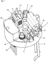
- Fig. 1 shows a brush side of a brush support plate 5, with brushes 6, which are designed here as carbon brushes, with brush boxes 24 for receiving and guiding the brushes 6, brush springs 26 for generating a pressing force of the brushes 6 on a commutator brushes 27 for powering the brushes, throttle shots 28 for receiving inductors as part of a suppression circuit, a sensor housing 25 for receiving and shielding a circuit board from contamination and heat, supply lines 16 and control lines 15 for supplying the circuit board.
- Fig. 2 shows a sensor side of the brush support plate 5, with the circuit board 9, a magnetic field sensor 7, a grommet 19, a partition wall 22 which axially separates the brush side from the sensor side, the supply lines 16, the control lines 15, an annular wall 10, which with the brush support plate. 5 is integral and has a recess 11 in which the magnetic field sensor 7 is arranged.
- the annular wall 10 serves as a further component of the sensor housing 25.
- a brush 6 and a brush holder 24 are shown.
- the circuit board 9 is mounted in groove-like receptacles 12. With the mounting of the circuit board, the position of the magnetic field sensor is clearly defined.
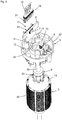
- Fig. 3 shows an exploded view of some components of a commutator, with a rotor 3, the brush holder plate 5, the circuit board 9 and the control lines 15.
- the rotor 3 has a shaft 29, a rotor core 30, a commutator 20, a winding 13 and a magnetic flywheel 8.
- the circuit board 9 is designed here T-shaped design.
- the magnetic field sensor 7 is arranged and on the opposite second side of the plug 17 is arranged with a pin header 23.
- the plug-in direction for the plug is paraxial.
- the control lines 15 are encapsulated with a sealing material, whereby the rubber grommet 19 is formed.
- the control lines 15 terminate in a contact strip 31.
- the annular wall 10, with the recess 11, the partition wall 22 and a radial outer wall 32 are further shown.
- Fig. 4 shows a view of a mounted commutator motor 1, with a permanent magnet stator 4, which also forms a cylindrical outer housing, a bearing plate 14, with a through hole 18 for the control lines 15, the supply lines 16, the shaft 29 and the rotor axis 21st LIST OF REFERENCE NUMBERS 1 commutator 29 wave 2 casing 30 Laminated core 3 rotor 31 contact strip 4 permanent magnet stator 32 outer wall 5 Brush-holder plate 6 brush 7 magnetic field sensor 8th flywheel 9 circuit board 10 ring wall 11 recess 12 admission 13 winding 14 end shield 15 control line 16 supply line 17 plug 18 Through opening 19 grommet 20 commutator 21 rotor axis 22 partition wall 23 pin header 24 brush holder 25 sensor housing 26 brush spring 27 pigtail 28 throttle intake
Landscapes
- Engineering & Computer Science (AREA)
- Power Engineering (AREA)
- Dc Machiner (AREA)
Abstract
Description
- Die Erfindung betrifft einen Kommutatormotor (1) mit einem Gehäuse (2), einem eine Wicklung (13), einen Kommutator (20) und ein magnetisches Polrad (8) tragenden und um eine Rotorachse (21) drehbar gelagerten Rotor (3), einem Permanentmagnetstator (4), einer im Wesentlichen rechtwinklig zur Rotorachse (21) angeordneten Bürstentragplatte (5) mit Bürsten (6), welche mit dem Kommutator (20) in Kontakt stehen, einem innerhalb des Gehäuses (2) angeordneten Encoder, bestehend aus einem Magnetfeldsensor (7) und dem Polrad (8).
- Bei vielen Anwendungen ist es erforderlich Elektromotoren mit Encodern auszustatten. Die Auflösung kann zum Beispiel bis zu 2048 Impulsen pro Umdrehung betragen. Häufig soll auch eine Drehrichtungserkennung vorhanden sein. Hochauflösende Encoder sind oft optische Encoder, die außerhalb des Motorgehäuses an einem Ausgang des Motors angeordnet sind. Dies erhöht den axialen Bauraum und schränkt die Nutzungsmöglichkeiten des Elektromotors ein. Beispielsweise ist es schwierig z. B. eine Motorbremse, ein Lüfterrad oder dgl. neben einem anzutreibenden Getriebe am Elektromotor anzubauen. Bei Kommutatormotoren sind in der Regel Kohlebürsten im Einsatz, deren Abrieb optische Encoder bei Einbau im Motor unbrauchbar machen kann. Da der Abrieb aus leitenden Partikeln besteht, können diese Kurzschlüsse auf Leiterplatten hervorrufen.
- Aus der
DE 10 2014 007 242 A1 ist ein gattungsgemäßer Kommutatormotor bekannt, bei dem ein Magnetfeldsensor auf einer Leiterplatte und diese auf einer Bürstentragplatte angeordnet ist. Die Leiterplatte ist relativ ungeschützt dem Kohleabrieb und einer thermischen Beeinträchtigung durch das unvermeidliche Bürstenfeuer ausgesetzt, so dass Kurzschlüsse nicht auszuschließen sind. - Aufgabe der Erfindung ist es daher bei einem gattungsgemäßen Kommutator für einen möglichst zuverlässigen Betrieb mit minimierter Gefahr von Kurzschlüssen zu sorgen, wobei der Kommutatormotor möglichst vielseitig einsetzbar ist. Weiter ist es Aufgabe der Erfindung eine Baureihe von Kommutatormotoren bereitzustellen, welche skalierbare Motordurchmesser von ca. 40mm, ca. 50mm, ca. 60mm und ca. 80mm mit dem gleichen Konzept und gleichen Fertigungsabläufen erlaubt. Weiter sollen einfache, gut beherrschbare Fertigungsprozesse einsetzbar sein, die vorzugsweise automatisierbar sind. Nach Möglichkeit sollen beide Wellenenden frei bleiben.
- Diese Aufgabe wird erfindungsgemäß durch die Merkmale der Ansprüche 1 und 18 gelöst. Da die Bürsten (6) axial auf einer ersten Seite einer Trennwand (22) der Bürstentragplatte (5) angeordnet sind und der Magnetfeldsensor (7) axial auf einer zweiten gegenüberliegenden Seite der Bürstentragplatte (5) angeordnet ist, wird der Magnetfeldsensor oder eine Sensorleiterplatte vor dem Kohleabrieb abgeschirmt. Kohlestaub kann daher nicht zu Kurzschlüssen führen. Zusätzlich wirkt die Trennwand (22) als Abschirmung vor dem Bürstenfeuer und deren mögliche thermische Beeinträchtigung des Magnetfeldsensors (7).
- Weiterbildungen der Erfindung werden in den Unteransprüchen dargestellt. Da auch die Wicklung thermisch auf den Magnetfeldsensor (7) einwirken kann ist dieser axial auf einer der Wicklung (13) abgewandten Seite der Bürstentragplatte (5) angeordnet.
- Zweckmäßigerweise ist der Magnetfeldsensor auf einer Leiterplatte (9) angeordnet. Hierdurch können weitere Bauteile, die für den Betrieb des Magnetfeldsensors (7) notwendig sind, auf einfache Weise mit diesem zu einer Baugruppe vereinigt werden. Zudem ist die Montage und Kontaktierung des Magnetfeldsensors (7) auf diese Weise vereinfacht.
- Da der Magnetfeldsensor (7) vorzugsweise radial gegenüber dem Polrad angeordnet werden soll, ist es sinnvoll die Leiterplatte (9) parallel zu der Rotorachse (21) ausgerichtet anzuordnen. Auf diese Weise lassen sich auch einfach oberflächenmontierte Bauteile verwenden.
- Um die Montage zu vereinfachen, wird die Leiterplatte (9) in Aufnahmen (12) der Bürstentragplatte (5) achsparallel eingeschoben. Hierdurch stimmt die Montagerichtung mit derjenigen für sonstige auf der Bürstentragplatte zu montierende Bauteile überein. Die Aufnahmen sind so gestaltet, dass die Leiterplatte (9) auf Anschlag eingesetzt wird und kein Nachjustieren notwendig ist.
- Eine noch bessere Abschirmung vor Kohleabrieb und Bürstenfeuer, insbesondere der Leiterplatte (9), wird dadurch erreicht, dass die Bürstentragplatte (5) eine im Wesentlichen konzentrisch um eine Motorachse angeordnete Ringwand (10) aufweist, der Magnetfeldsensor (7) in einer Ausnehmung der Ringwand (10) und die Leiterplatte im Wesentlichen radial außerhalb der Ringwand angeordnet ist. Die Ausnehmung sollte dabei so dimensioniert sein, dass der Magnetfeldsensor problemlos montiert werden kann, aber so wenig Spielraum wie möglich zwischen Magnetfeldsensor und Ringwand (10) verbleibt, welche die abschirmende Wirkung der Ringwand (10) abschwächt.
- Nach einer Weiterbildung der Erfindung ist auf der Leiterplatte (9) ein Überspannungsschutz mit einem Nominalwert für die Spannungssignale von 3,7V, 5V, 12V, 24V, 40V oder 48V vorgesehen.
- Außerdem ist es optional vorgesehen, die Leiterplatte mit einem Spannungsregler auszurüsten, der die Ausgangssignale mit einer Spannung 3,7V, 5V, 12V, 40V oder 48V ausgibt.
- Oft ist auch eine Temperaturüberwachung nötig, deshalb kann die Leiterplatte auch mit einem Temperatursensor versehen sein.
- Um die Leiterplatte (9) mit Spannung und Steuersignalen zu versorgen hat die Leiterplatte (9) eine Klemme, einen Stecker (17) mit einer Stiftleiste (23) oder Press-Fit Pins.
- Versorgungsleitungen (Zuleitungen) enden in einer Kontaktleiste (31), welche in die Stiftleiste (23) einrastet und somit für eine Zugentlastung sorgt.
- Alternativ ist es auch denkbar, zur Kontaktierung Kontakte mit federnden Zungen zu verwenden, die auf die Seitenkanten der Leiterplatte aufgeschoben werden. Vorteilhafterweise ist die Steckrichtung des Steckers (17) achsparallel. Dadurch sind auch die Versorgungsleitungen in der Hauptmontagerichtung montierbar.
- Das Lagerschild (14) weist eine Durchgangsöffnung (18) auf, welche eine Dichtungstülle (19) und die Versorgungsleitungen (16) und/oder die Steuerleitungen (15) aufnimmt. Die Dichtungstülle füllt den Raum zwischen den Versorgungsleitungen (16) und/oder den Steuerleitungen (15) aus und dichtet den Kommutatormotor ab.
- Nach einer Weiterbildung der Erfindung sind die Versorgungsleitungen (16) und/oder die Steuerleitungen (15) mit einer Dichtmasse umspritzt, umgossen oder auf andere Weise umhüllt, welche die Dichtungstülle bildet. Dadurch kann eine spritzwasserdichte Anordnung hergestellt werden.
- Im Übrigen ist vorgesehen, dass der Magnetfeldsensor (7) ein Hallsensor mit analogem oder digitalem Ausgang ist und das Polrad (8) zwischen zwei und dreißig Polpaare aufweist.
- Damit auch höhere Auflösungen realisierbar sind, ist alternativ vorgesehen, dass ein Hallsensor-Array oder ein Sensor auf Grundlage des magnetoresistiven Effekts, wie GMR-Sensor, AMR-Sensor, CMR-Sensor, TMR-Sensor als Magnetfeldsensor (7) verwendet wird.
- Besondere Vorteile werden dadurch erzielt, dass die Leiterplatte eine programmierbare Steuerung aufweist, wobei durch eine Programmierung eine Impulszahl pro Umdrehung, und/oder eine Drehrichtungserkennung und/oder eine Indexierung festlegbar ist. Die Programmierung erfolgt vorzugsweise nach der Montage des Motors über die Steuerleitungen (15).
- Die Erfindung wird weiter durch eine Baureihe von Kommutatormotoren gemäß Anspruch 16 gelöst. Es ist vorgesehen, dass sich die einzelnen Kommutatormotoren durch unterschiedliche Motordurchmesser und/oder Motorlängen und/oder Ausstattungsvarianten unterscheiden, wobei die Ausstattungsvarianten folgende Ausstattungsmerkmale aufweisen: die Bürstentragplatte (5), den Encoder, einer Leiterplatte und Steuerleitungen (15). Durch Variation und Kombination dieser Merkmale lässt sich eine Vielzahl unterschiedlicher Kommutatormotoren bereitstellen, die für unterschiedlichste Anforderungen gerüstet sind.
- Je nach gewünschter Auflösung kann der Encoder in einer Ausstattungsvariante einen GMR-Sensor oder ein Hallsensor-Array und ein zweipoliges Polrad aufweisen. Mit dieser Anordnung lassen sich bis zu 2048 Impulse pro Umdrehung erzeugen.
- Falls eine geringere Auflösung bis 60 Impulse ausreicht kann in einer weiteren Ausstattungsvariante einen Hallsensor und ein mehrpoliges Polrad mit einer Polpaarzahl >= 1 und <= 30 verwendet werden.
- Häufig ist es wirtschaftlicher, Kommutatormotoren mit gleicher Bauweise in großen Stückzahlen herzustellen und Ausführungsvarianten allein durch unterschiedliche Programmierung zu erreichen. Daher ist in einer Ausstattungsvariante vorgesehen, dass der Encoder mit oder ohne einer programmierbaren elektronischen Schaltung ausgerüstet ist.
- Je nach Anforderungen an die Auswertung kann es sinnvoll sein in einer Ausstattungsvariante einen Encoder mit einem Magnetfeldsensor zu verwenden, welcher einen digitalen oder in einem anderen Fall einen analogen Ausgang aufweist.
- In vielen Anwendungen mit erhöhten Anforderungen sind Leiterplatten mit integriertem Überspannungsschutz gefordert. In einer Ausstattungsvariante ist eine Leiterplatte mit einem Überspannungsschutz ausgerüstet, alternativ zu einer Leiterplatte ohne Überlastschutz.
- Vielfach ist es sinnvoll die Spannung zu regeln, deshalb ist in einer Ausstattungsvariante eine Leiterplatte mit einem Spannungsregler ausgerüstet, alternativ zu einer Leiterplatte ohne Spannungsregler.
- Auch die Temperatur ist häufig zu überwachen, in einer Ausstattungsvariante ist daher eine Leiterplatte mit einem Temperatursensor ausgerüstet, alternativ zu einer Leiterplatte ohne Temperatursensor.
- Bei komplexen Anwendungen kann gegenüber einfacheren Anwendungen eine erhöhte Anzahl an Steuerleitungen erforderlich sein, daher ist in einer Ausstattungsvariante eine Leiterplatte (9) mit fünf oder acht Steuerleitungen vorgesehen. Dabei sind jeweils zwei Steuerleitungen für die Versorgung, zwei für jeweils einen Kanal, eine für eine Indexierung. Bei acht Steuerleitungen sind die Kanalleitungen und die Indexierungsleitung jeweils mit einer invertierten Version ergänzt.
- Zweckmäßigerweise lassen sich auch unterschiedliche Ausstattungsvarianten hinsichtlich der Dichtung bei der Durchführung der Steuerleitungen (15) durch den Lagerschild darstellen. Als Varianten sind hierfür umspritzte oder montierte Gummitüllen oder einer Flüssigdichtung vorgesehen.
- Weitere Kombinationsmöglichkeiten bestehen darin in einer Ausstattungsvariante die Leiterplatte (9) mittels einer Klemme, einer Stiftleiste (23) oder Press-Fit Pins, die mit einer Kontaktleiste verbunden sind oder mittels federnder Zungen, die auf Seitenkanten der Leiterplatte aufgeschoben sind, zu kontaktieren.
- Die Baureihe ist dadurch gekennzeichnet, dass sie gut skalierbar ist und mit wenigen Bauteilvarianten eine große Anzahl an unterschiedlichen Kommutatormotoren bereitgestellt werden kann. Die Montage ist gekennzeichnet durch einfache Steckprozesse, die leicht zu automatisieren sind. Das Design ist robust und beide Wellenenden lassen sich für Abtriebs- oder Bremsfunktionen nutzen.
- Ein Ausführungsbeispiel der Erfindung wird nachfolgend anhand der Zeichnung näher erläutert. Es zeigen:
-
Fig. 1 eine Bürstenseite einer Bürstentragplatte, -
Fig. 2 eine Sensorseite der Bürstentragplatte, -
Fig. 3 eine Explosionsdarstellung einiger Bauteile eines Kommutatormotors und -
Fig. 4 eine Ansicht eines montierten Kommutatormotors. -
Fig. 1 zeigt eine Bürstenseite einer Bürstentragplatte 5, mit Bürsten 6, welche hier als Kohlebürsten ausgeführt sind, mit Bürstenköchern 24 zur Aufnahme und Führung der Bürsten 6, Bürstenfedern 26 zur Erzeugung einer Andruckkraft der Bürsten 6 auf einen Kommutator, Bürstenlitzen 27 zur Spannungsversorgung der Bürsten, Drosselaufnahmen 28 zur Aufnahme von Drosselspulen als Bestandteil einer Entstörschaltung, ein Sensorgehäuse 25 zur Aufnahme und Abschirmung einer Leiterplatte vor Verschmutzung und Wärmeeinwirkung, Versorgungsleitungen 16 und Steuerleitungen 15 zur Versorgung der Leiterplatte. -
Fig. 2 zeigt eine Sensorseite der Bürstentragplatte 5, mit der Leiterplatte 9, einem Magnetfeldsensor 7, einer Dichtungstülle 19, einer Trennwand 22, welche axial die Bürstenseite von der Sensorseite trennt, den Versorgungsleitungen 16, den Steuerleitungen 15, einer Ringwand 10, welche mit der Bürstentragplatte 5 einstückig ist und eine Ausnehmung 11 aufweist, in welcher der Magnetfeldsensor 7 angeordnet ist. Die Ringwand 10 dient als weiterer Bestandteil des Sensorgehäuses 25. Weiter sind eine Bürste 6 und ein Bürstenköcher 24 dargestellt. Die Leiterplatte 9 ist in nutartigen Aufnahmen 12 montiert. Mit der Montage der Leiterplatte ist die Lage des Magnetfeldsensors eindeutig definiert. -
Fig. 3 zeigt eine Explosionsdarstellung einiger Bauteile eines Kommutatormotors, mit einem Rotor 3, der Bürstentragplatte 5, der Leiterplatte 9 und den Steuerleitungen 15. Der Rotor 3 weist eine Welle 29, ein Rotorblechpaket 30, einen Kommutator 20 eine Wicklung 13 und ein magnetisches Polrad 8 auf. Bei der Bürstentragplatte 5 ist deutlicher als inFig. 2 die nutartige Aufnahme 12 für die Leiterplatte 9 zu erkennen. Die Leiterplatte 9 ist hier konstruktionsbedingt T-förmig ausgebildet. Auf einer ersten Seite der Leiterplatte 9 ist der Magnetfeldsensor 7 angeordnet und auf der gegenüberliegenden zweiten Seite ist der Stecker 17 mit einer Stiftleiste 23 angeordnet. Die Steckrichtung für den Stecker ist achsparallel. Die Steuerleitungen 15 sind mit einem Dichtungsmaterial umspritzt, wodurch die Gummitülle 19 gebildet ist. Die Steuerleitungen 15 enden in einer Kontaktleiste 31. Bei der Bürstentragplatte 5 sind weiter die Ringwand 10, mit der Ausnehmung 11, die Trennwand 22 und eine radiale Außenwand 32 dargestellt. -
Fig. 4 zeigt eine Ansicht eines montierten Kommutatormotors 1, mit einem Permanentmagnetstator 4, der zugleich ein zylindrisches Außengehäuse bildet, einen Lagerschild 14, mit einer Durchgangsöffnung 18 für die Steuerleitungen 15, die Versorgungsleitungen 16, die Welle 29 und die Rotorachse 21.Bezugszeichenliste 1 Kommutatormotor 29 Welle 2 Gehäuse 30 Rotorblechpaket 3 Rotor 31 Kontaktleiste 4 Permanentmagnetstator 32 Außenwand 5 Bürstentragplatte 6 Bürste 7 Magnetfeldsensor 8 Polrad 9 Leiterplatte 10 Ringwand 11 Ausnehmung 12 Aufnahme 13 Wicklung 14 Lagerschild 15 Steuerleitung 16 Versorgungsleitung 17 Stecker 18 Durchgangsöffnung 19 Dichtungstülle 20 Kommutator 21 Rotorachse 22 Trennwand 23 Stiftleiste 24 Bürstenköcher 25 Sensorgehäuse 26 Bürstenfeder 27 Bürstenlitze 28 Drosselaufnahme
Claims (29)
- Kommutatormotor (1) mit einem Gehäuse (2), einem eine Wicklung (13), einen Kommutator (20) und ein magnetisches Polrad (8) tragenden und um eine Rotorachse (21) drehbar gelagerten Rotor (3), einem Permanentmagnetstator (4), einer im Wesentlichen rechtwinklig zur Rotorachse (21) angeordneten Bürstentragplatte (5) mit Bürsten (6), welche mit dem Kommutator (20) in Kontakt stehen, einem innerhalb des Gehäuses (2) angeordneten Encoder, bestehend aus einem Magnetfeldsensor (7) und dem Polrad (8), dadurch gekennzeichnet, dass die Bürsten (6) axial auf einer ersten Seite einer Trennwand (22) der Bürstentragplatte (5) angeordnet sind und der Magnetfeldsensor (7) axial auf einer zweiten gegenüberliegenden Seite der Bürstentragplatte (5) angeordnet ist.
- Kommutatormotor nach Anspruch 1, dadurch gekennzeichnet, dass der Magnetfeldsensor (7) axial auf einer der Wicklung (13) abgewandten Seite der Bürstentragplatte (5) angeordnet ist.
- Kommutatormotor nach Anspruch 1 oder 2, dadurch gekennzeichnet, dass der Magnetfeldsensor auf einer Leiterplatte (9) angeordnet und befestigt ist.
- Kommutatormotor nach Anspruch 3, dadurch gekennzeichnet, dass die Leiterplatte (9) parallel zu der Rotorachse (21) ausgerichtet ist.
- Kommutatormotor nach Anspruch 3 oder 4, dadurch gekennzeichnet, dass die Leiterplatte (9) in Aufnahmen (12) der Bürstentragplatte (5) achsparallel eingeschoben sind.
- Kommutatormotor nach Anspruch 3, 4 oder 5, dadurch gekennzeichnet, dass die Bürstentragplatte (5) eine im Wesentlichen konzentrisch um eine Motorachse angeordnete Ringwand (10) aufweist, der Magnetfeldsensor (7) in einer Ausnehmung der Ringwand (10) und die Leiterplatte im Wesentlichen radial außerhalb der Ringwand angeordnet ist.
- Kommutatormotor nach zumindest einem der Ansprüche 3 bis 6, dadurch gekennzeichnet, dass die Leiterplatte (9) einen Überspannungsschutz mit einem Nominalwert für die Spannungssignale von 3,7V, 5V, 12V, 24V, 40V oder 48V aufweist.
- Kommutatormotor nach zumindest einem der Ansprüche 3 bis 7, dadurch gekennzeichnet, dass die Leiterplatte (9) einen Spannungsregler enthält, der die Ausgangssignale wahlweise mit einer Spannung von 3,7V, 5V, 12V, 24V, 40V oder 48V ausgibt.
- Kommutatormotor nach zumindest einem der Ansprüche 3 bis 8, dadurch gekennzeichnet, dass die Leiterplatte (9) einen Temperatursensor enthält.
- Kommutatormotor nach zumindest einem der Ansprüche 3 bis 9, dadurch gekennzeichnet, dass die Leiterplatte (9) einen Stecker (17) mit einer Klemme, einer Stiftleiste (23) oder Press-Fit Pins aufweist.
- Kommutatormotor nach Anspruch 10, dadurch gekennzeichnet, dass Versorgungsleitungen (Zuleitungen) in einer Kontaktleiste enden, welche in die Stiftleiste (23) einrastet.
- Kommutatormotor nach Anspruch 10 oder 11, dadurch gekennzeichnet, dass die Steckrichtung des Steckers (17) achsparallel ist.
- Kommutatormotor nach Anspruch 11 oder 12, dadurch gekennzeichnet, dass das Lagerschild (14) eine Durchgangsöffnung (18) aufweist, welche eine Dichtungstülle (19) und die Versorgungsleitungen (16) und/oder die Steuerleitungen (15) aufnimmt.
- Kommutatormotor nach Anspruch 13, dadurch gekennzeichnet, dass die Versorgungsleitungen (16) und/oder die Steuerleitungen (15) mit einer Dichtmasse umspritzt, umgossen oder auf andere Weise umhüllt sind, welche die Dichtungstülle (19) bildet.
- Kommutatormotor nach zumindest einem der vorangehenden Ansprüche, dadurch gekennzeichnet, dass der Magnetfeldsensor (7) ein Hallsensor mit analogem oder digitalem Ausgang ist und das Polrad (8) zwischen einem Polpaar und dreißig Polpaare aufweist.
- Kommutatormotor nach zumindest einem der vorangehenden Ansprüche, dadurch gekennzeichnet, dass der Magnetfeldsensor (7) ein Sensor auf Grundlage des magnetoresistiven Effekts, wie GMR-Sensor, AMR-Sensor, CMR-Sensor, TMR-Sensor oder ein Hallsensor-Array ist und das Polrad (8) zweipolig ist.
- Kommutatormotor nach zumindest einem der Ansprüche 3 bis 16, dadurch gekennzeichnet, dass die Leiterplatte eine programmierbare Steuerung aufweist, wobei durch eine Programmierung eine Impulszahl pro Umdrehung, und/oder eine Drehrichtungserkennung und/oder eine Indexierung festlegbar ist.
- Baureihe von Kommutatormotoren (1) mit jeweils einem Gehäuse (2), einem eine Wicklung (13), einen Kommutator (20) und ein magnetisches Polrad (8) tragenden und um eine Rotorachse (21) drehbar gelagerten Rotor (3), einem Permanentmagnetstator (4), einer im Wesentlichen rechtwinklig zur Rotorachse (21) angeordneten Bürstentragplatte (5) mit Bürsten (6), welche mit dem Kommutator (20) in Kontakt stehen, einem innerhalb des Gehäuses (2) angeordneten Encoder, bestehend aus einem Magnetfeldsensor (7) und dem Polrad (8), dadurch gekennzeichnet, dass sich die einzelnen Kommutatormotoren durch unterschiedliche Motordurchmesser und/oder Motorlängen und/oder Ausstattungsvarianten unterscheiden, wobei die Ausstattungsvarianten folgende Ausstattungsmerkmale aufweisen: die Bürstentragplatte (5), den Encoder, einer Leiterplatte und Steuerleitungen (15).
- Baureihe nach Anspruch 18, dadurch gekennzeichnet, dass der Encoder in einer Ausstattungsvariante einen GMR-Sensor oder ein Hallsensor-Array und ein zweipoliges Polrad aufweist.
- Baureihe nach Anspruch 18, dadurch gekennzeichnet, dass der Encoder in einer Ausstattungsvariante einen Hallsensor und ein mehrpoliges Polrad mit einer Polpaarzahl >= 2 und <= 30 aufweist.
- Baureihe nach Anspruch 18, 19 oder 20, dadurch gekennzeichnet, dass der Encoder in einer Ausstattungsvariante mit oder ohne einer programmierbaren elektronischen Schaltung ausgerüstet ist.
- Baureihe nach Anspruch 18, 19, 20 oder 21, dadurch gekennzeichnet, dass der Encoder in einer Ausstattungsvariante einen Magnetfeldsensor mit einem digitalen oder einem analogen Ausgang aufweist.
- Baureihe nach Anspruch 18, 19, 20, 21 oder 22, dadurch gekennzeichnet, dass die Leiterplatte (9) in einer Ausstattungsvariante mit oder ohne einen integrierten Überspannungsschutz ausgerüstet ist.
- Baureihe nach zumindest einem der Ansprüche 18 bis 23, dadurch gekennzeichnet, dass die Leiterplatte (9) in einer Ausstattungsvariante mit einem Spannungsregler ausgerüstet ist.
- Baureihe nach zumindest einem der Ansprüche 18 bis 24, dadurch gekennzeichnet, dass die Leiterplatte (9) in einer Ausstattungsvariante mit einem Temperatursensor ausgerüstet ist.
- Baureihe nach zumindest einem der Ansprüche 18 bis 25, dadurch gekennzeichnet, dass die Leiterplatte (9) in einer Ausstattungsvariante mit fünf oder acht Steuerleitungen (15) ausgerüstet ist, wobei jeweils zwei Leitungen für die Versorgung, für mehrere Kanäle und/oder für eine Indexierung, sowie für invertierte Kanäle und Indexierung verwendet werden.
- Baureihe nach zumindest einem der Ansprüche 18 bis 26, dadurch gekennzeichnet, dass die Steuerleitungen (15) in einer Ausstattungsvariante mit einer umspritzten oder montierten Gummitülle oder einer Flüssigdichtung durch den Lagerschild geführt sind.
- Baureihe nach zumindest einem der Ansprüche 18 bis 27, dadurch gekennzeichnet, dass die Leiterplatte (9) in einer Ausstattungsvariante mittels einer Klemme, einer Stiftleiste (23) oder Press-Fit Pins, welche mit einer Kontaktleiste oder mittels federnder Zungen, die auf Seitenkanten der Leiterplatte aufgeschoben sind, kontaktiert ist.
- Baureihe nach einem der Ansprüche 18 bis 28, wobei alle Kommutatormotoren der Baureihe wenigstens nach einem der Ansprüche 1 bis 17 ausgebildet sind.
Applications Claiming Priority (1)
| Application Number | Priority Date | Filing Date | Title |
|---|---|---|---|
| DE102017223061.4A DE102017223061A1 (de) | 2017-12-18 | 2017-12-18 | Kommutatormotor und baureihe von kommutatormotoren |
Publications (3)
| Publication Number | Publication Date |
|---|---|
| EP3499693A2 true EP3499693A2 (de) | 2019-06-19 |
| EP3499693A3 EP3499693A3 (de) | 2019-09-04 |
| EP3499693B1 EP3499693B1 (de) | 2021-07-28 |
Family
ID=64606803
Family Applications (1)
| Application Number | Title | Priority Date | Filing Date |
|---|---|---|---|
| EP18210317.6A Active EP3499693B1 (de) | 2017-12-18 | 2018-12-05 | Kommutatormotor und baureihe von kommutatormotoren |
Country Status (2)
| Country | Link |
|---|---|
| EP (1) | EP3499693B1 (de) |
| DE (1) | DE102017223061A1 (de) |
Family Cites Families (14)
| Publication number | Priority date | Publication date | Assignee | Title |
|---|---|---|---|---|
| JPS59126599U (ja) * | 1983-02-16 | 1984-08-25 | 日産自動車株式会社 | 電気自動車用電動機の制御装置 |
| DE59005769D1 (de) * | 1990-12-07 | 1994-06-23 | Siemens Ag | Bürstensystem für einen Kommutatormotor. |
| DE4326391C2 (de) * | 1993-08-06 | 1997-04-30 | Licentia Gmbh | Dreherkennungsvorrichtung für einen Kommutatormotor |
| DE19521395B4 (de) * | 1995-06-13 | 2007-05-10 | Temic Automotive Electric Motors Gmbh | Bürstenbrücke für einen Kollektormotor mit einem zylinderförmigen Gehäuse |
| DE19739682A1 (de) * | 1997-09-10 | 1999-03-11 | Bosch Gmbh Robert | Sensoreinrichtung |
| US6497035B1 (en) * | 1999-12-06 | 2002-12-24 | Hr Textron, Inc. | Hall position sensor |
| DE10357018A1 (de) * | 2003-12-05 | 2005-08-25 | Valeo Systèmes d`Essuyage | Elektromotorischer Antrieb |
| DE102006029052A1 (de) * | 2005-07-08 | 2007-01-18 | Phoenix-Mecano Kecskemet Kft. | Motorensystem |
| KR200470057Y1 (ko) * | 2009-05-11 | 2013-11-25 | 주식회사 모아텍 | 어스피레이션 모터의 핀 헤더 |
| DE102010063922A1 (de) * | 2010-12-22 | 2012-06-28 | Robert Bosch Gmbh | Bürstenmotor und Verfahren zum Schutz vor Überspannung für einen Bürstenmotor |
| CN102593997B (zh) * | 2011-01-07 | 2016-08-03 | 德昌电机(深圳)有限公司 | 电机 |
| DE102014007242B4 (de) | 2014-05-16 | 2024-02-22 | Nidec Motors & Actuators (Germany) Gmbh | Bürstenhaltevorrichtung für eine Kommutatormaschine |
| EP2983288B1 (de) * | 2014-08-08 | 2021-07-28 | Johnson Electric International AG | Treiberschaltung für einen permanentmagnetmotor |
| DE102016101963A1 (de) * | 2016-02-04 | 2017-08-10 | Bühler Motor GmbH | Elektromotor für eine Fluidpumpe, modulare Motorfamilie zur Bildung unterschiedlicher Fluidpumpen mit mehreren solcher Elektromotoren und Herstellungsverfahren |
-
2017
- 2017-12-18 DE DE102017223061.4A patent/DE102017223061A1/de not_active Withdrawn
-
2018
- 2018-12-05 EP EP18210317.6A patent/EP3499693B1/de active Active
Also Published As
| Publication number | Publication date |
|---|---|
| EP3499693A3 (de) | 2019-09-04 |
| DE102017223061A1 (de) | 2019-06-19 |
| EP3499693B1 (de) | 2021-07-28 |
Similar Documents
| Publication | Publication Date | Title |
|---|---|---|
| EP3411940B1 (de) | Elektromotor für eine fluidpumpe, modulare motorfamilie zur bildung unterschiedlicher fluidpumpen mit mehreren solcher elektromotoren und herstellungsverfahren | |
| EP3939148B1 (de) | Antriebsvorrichtung mit einem bürstenlosen elektromotor | |
| EP3928419B1 (de) | Antriebsvorrichtung mit einem bürstenlosen elektromotor | |
| EP3078099A2 (de) | Stator für einen elektronisch kommutierten gleichstrommotor | |
| DE102012218847A1 (de) | Anschlusselement für eine Antriebsanordnung sowie eine Antriebsanordnung mit einem Anschlussteil | |
| DE102013222534A1 (de) | Elektromaschine | |
| EP0666424A1 (de) | Lüfter mit einem Lüfterrad | |
| EP1703620A2 (de) | Elektrischer Antrieb | |
| DE102017216075A1 (de) | Stator für eine elektrische Maschine, eine elektrische Maschine und Verfahren zum Herstellen eines solchen Stators | |
| DE4326391C2 (de) | Dreherkennungsvorrichtung für einen Kommutatormotor | |
| DE102014225242A1 (de) | Verbindungsvorrichtung zwischen Statorwicklung und Steuereinrichtung einer elektrischen Maschine | |
| DE102021208084A1 (de) | Elektrische Maschine mit einer ein Statorgehäuse kontaktierenden Elektronikplatine | |
| DE3805060A1 (de) | Elektromotor mit einem systemtraeger zur aufnahme von bauelementen, leiterbahnen und steuer- bzw. regelbausteinen | |
| WO2008098681A1 (de) | Bürstenkommutierter elektromotor | |
| DE102006008416A1 (de) | Elektrischer Antrieb für einen verstellbaren Stabilisator | |
| DE102007044399A1 (de) | Vierpoliger elektromotorischer Antrieb mit einem Hammerbürstenhaltersystem | |
| DE29901967U1 (de) | Elektromotor mit einer Anordnung zur Drehzahlüberwachung | |
| DE102009001714A1 (de) | Elektrischer Antriebsmotor, insbesondere für ein Aggregat in einem Kraftfahrzeug | |
| EP3499693B1 (de) | Kommutatormotor und baureihe von kommutatormotoren | |
| DE102018221859B4 (de) | Kommutatormotor und Baureihe von Kommutatormotoren | |
| DE102006030611B4 (de) | Primärteil für einen elektrischen Linearmotor | |
| DE102018200195B4 (de) | Antrieb mit einem kommutatormotor | |
| DE102010062034A1 (de) | Schirmungsanordnung für einen bürstenkommutierten Elektromotor sowie Stellgeber mit einem Elektromotor | |
| WO2018091242A1 (de) | Elektrische maschine | |
| DE202009007545U1 (de) | Elektromotor |
Legal Events
| Date | Code | Title | Description |
|---|---|---|---|
| PUAI | Public reference made under article 153(3) epc to a published international application that has entered the european phase |
Free format text: ORIGINAL CODE: 0009012 |
|
| STAA | Information on the status of an ep patent application or granted ep patent |
Free format text: STATUS: THE APPLICATION HAS BEEN PUBLISHED |
|
| AK | Designated contracting states |
Kind code of ref document: A2 Designated state(s): AL AT BE BG CH CY CZ DE DK EE ES FI FR GB GR HR HU IE IS IT LI LT LU LV MC MK MT NL NO PL PT RO RS SE SI SK SM TR |
|
| AX | Request for extension of the european patent |
Extension state: BA ME |
|
| PUAL | Search report despatched |
Free format text: ORIGINAL CODE: 0009013 |
|
| AK | Designated contracting states |
Kind code of ref document: A3 Designated state(s): AL AT BE BG CH CY CZ DE DK EE ES FI FR GB GR HR HU IE IS IT LI LT LU LV MC MK MT NL NO PL PT RO RS SE SI SK SM TR |
|
| AX | Request for extension of the european patent |
Extension state: BA ME |
|
| RIC1 | Information provided on ipc code assigned before grant |
Ipc: H02K 5/22 20060101ALI20190730BHEP Ipc: H02K 11/25 20160101ALN20190730BHEP Ipc: H02K 11/215 20160101ALN20190730BHEP Ipc: H02K 11/26 20160101ALN20190730BHEP Ipc: H02K 13/10 20060101ALI20190730BHEP Ipc: H02K 5/14 20060101ALI20190730BHEP Ipc: H02K 23/66 20060101AFI20190730BHEP |
|
| STAA | Information on the status of an ep patent application or granted ep patent |
Free format text: STATUS: REQUEST FOR EXAMINATION WAS MADE |
|
| 17P | Request for examination filed |
Effective date: 20200219 |
|
| RBV | Designated contracting states (corrected) |
Designated state(s): AL AT BE BG CH CY CZ DE DK EE ES FI FR GB GR HR HU IE IS IT LI LT LU LV MC MK MT NL NO PL PT RO RS SE SI SK SM TR |
|
| STAA | Information on the status of an ep patent application or granted ep patent |
Free format text: STATUS: EXAMINATION IS IN PROGRESS |
|
| RIC1 | Information provided on ipc code assigned before grant |
Ipc: H02K 23/66 20060101AFI20200804BHEP Ipc: H02K 11/26 20160101ALN20200804BHEP Ipc: H02K 5/14 20060101ALI20200804BHEP Ipc: H02K 5/22 20060101ALI20200804BHEP Ipc: H02K 11/25 20160101ALN20200804BHEP Ipc: H02K 13/10 20060101ALI20200804BHEP Ipc: H02K 11/215 20160101ALN20200804BHEP |
|
| 17Q | First examination report despatched |
Effective date: 20200812 |
|
| GRAP | Despatch of communication of intention to grant a patent |
Free format text: ORIGINAL CODE: EPIDOSNIGR1 |
|
| STAA | Information on the status of an ep patent application or granted ep patent |
Free format text: STATUS: GRANT OF PATENT IS INTENDED |
|
| RIC1 | Information provided on ipc code assigned before grant |
Ipc: H02K 11/215 20160101ALN20210128BHEP Ipc: H02K 11/25 20160101ALN20210128BHEP Ipc: H02K 5/14 20060101ALI20210128BHEP Ipc: H02K 5/22 20060101ALI20210128BHEP Ipc: H02K 13/10 20060101ALI20210128BHEP Ipc: H02K 11/26 20160101ALN20210128BHEP Ipc: H02K 23/66 20060101AFI20210128BHEP |
|
| RIC1 | Information provided on ipc code assigned before grant |
Ipc: H02K 13/10 20060101ALI20210129BHEP Ipc: H02K 5/22 20060101ALI20210129BHEP Ipc: H02K 11/25 20160101ALN20210129BHEP Ipc: H02K 11/215 20160101ALN20210129BHEP Ipc: H02K 5/14 20060101ALI20210129BHEP Ipc: H02K 11/26 20160101ALN20210129BHEP Ipc: H02K 23/66 20060101AFI20210129BHEP |
|
| INTG | Intention to grant announced |
Effective date: 20210224 |
|
| GRAS | Grant fee paid |
Free format text: ORIGINAL CODE: EPIDOSNIGR3 |
|
| GRAA | (expected) grant |
Free format text: ORIGINAL CODE: 0009210 |
|
| STAA | Information on the status of an ep patent application or granted ep patent |
Free format text: STATUS: THE PATENT HAS BEEN GRANTED |
|
| AK | Designated contracting states |
Kind code of ref document: B1 Designated state(s): AL AT BE BG CH CY CZ DE DK EE ES FI FR GB GR HR HU IE IS IT LI LT LU LV MC MK MT NL NO PL PT RO RS SE SI SK SM TR |
|
| REG | Reference to a national code |
Ref country code: GB Ref legal event code: FG4D Free format text: NOT ENGLISH |
|
| REG | Reference to a national code |
Ref country code: CH Ref legal event code: EP |
|
| REG | Reference to a national code |
Ref country code: DE Ref legal event code: R096 Ref document number: 502018006294 Country of ref document: DE |
|
| REG | Reference to a national code |
Ref country code: AT Ref legal event code: REF Ref document number: 1415610 Country of ref document: AT Kind code of ref document: T Effective date: 20210815 |
|
| REG | Reference to a national code |
Ref country code: IE Ref legal event code: FG4D Free format text: LANGUAGE OF EP DOCUMENT: GERMAN |
|
| REG | Reference to a national code |
Ref country code: LT Ref legal event code: MG9D |
|
| REG | Reference to a national code |
Ref country code: NL Ref legal event code: MP Effective date: 20210728 |
|
| PG25 | Lapsed in a contracting state [announced via postgrant information from national office to epo] |
Ref country code: SE Free format text: LAPSE BECAUSE OF FAILURE TO SUBMIT A TRANSLATION OF THE DESCRIPTION OR TO PAY THE FEE WITHIN THE PRESCRIBED TIME-LIMIT Effective date: 20210728 Ref country code: RS Free format text: LAPSE BECAUSE OF FAILURE TO SUBMIT A TRANSLATION OF THE DESCRIPTION OR TO PAY THE FEE WITHIN THE PRESCRIBED TIME-LIMIT Effective date: 20210728 Ref country code: HR Free format text: LAPSE BECAUSE OF FAILURE TO SUBMIT A TRANSLATION OF THE DESCRIPTION OR TO PAY THE FEE WITHIN THE PRESCRIBED TIME-LIMIT Effective date: 20210728 Ref country code: ES Free format text: LAPSE BECAUSE OF FAILURE TO SUBMIT A TRANSLATION OF THE DESCRIPTION OR TO PAY THE FEE WITHIN THE PRESCRIBED TIME-LIMIT Effective date: 20210728 Ref country code: FI Free format text: LAPSE BECAUSE OF FAILURE TO SUBMIT A TRANSLATION OF THE DESCRIPTION OR TO PAY THE FEE WITHIN THE PRESCRIBED TIME-LIMIT Effective date: 20210728 Ref country code: BG Free format text: LAPSE BECAUSE OF FAILURE TO SUBMIT A TRANSLATION OF THE DESCRIPTION OR TO PAY THE FEE WITHIN THE PRESCRIBED TIME-LIMIT Effective date: 20211028 Ref country code: LT Free format text: LAPSE BECAUSE OF FAILURE TO SUBMIT A TRANSLATION OF THE DESCRIPTION OR TO PAY THE FEE WITHIN THE PRESCRIBED TIME-LIMIT Effective date: 20210728 Ref country code: PT Free format text: LAPSE BECAUSE OF FAILURE TO SUBMIT A TRANSLATION OF THE DESCRIPTION OR TO PAY THE FEE WITHIN THE PRESCRIBED TIME-LIMIT Effective date: 20211129 Ref country code: NL Free format text: LAPSE BECAUSE OF FAILURE TO SUBMIT A TRANSLATION OF THE DESCRIPTION OR TO PAY THE FEE WITHIN THE PRESCRIBED TIME-LIMIT Effective date: 20210728 Ref country code: NO Free format text: LAPSE BECAUSE OF FAILURE TO SUBMIT A TRANSLATION OF THE DESCRIPTION OR TO PAY THE FEE WITHIN THE PRESCRIBED TIME-LIMIT Effective date: 20211028 |
|
| PG25 | Lapsed in a contracting state [announced via postgrant information from national office to epo] |
Ref country code: PL Free format text: LAPSE BECAUSE OF FAILURE TO SUBMIT A TRANSLATION OF THE DESCRIPTION OR TO PAY THE FEE WITHIN THE PRESCRIBED TIME-LIMIT Effective date: 20210728 Ref country code: LV Free format text: LAPSE BECAUSE OF FAILURE TO SUBMIT A TRANSLATION OF THE DESCRIPTION OR TO PAY THE FEE WITHIN THE PRESCRIBED TIME-LIMIT Effective date: 20210728 Ref country code: GR Free format text: LAPSE BECAUSE OF FAILURE TO SUBMIT A TRANSLATION OF THE DESCRIPTION OR TO PAY THE FEE WITHIN THE PRESCRIBED TIME-LIMIT Effective date: 20211029 |
|
| PG25 | Lapsed in a contracting state [announced via postgrant information from national office to epo] |
Ref country code: DK Free format text: LAPSE BECAUSE OF FAILURE TO SUBMIT A TRANSLATION OF THE DESCRIPTION OR TO PAY THE FEE WITHIN THE PRESCRIBED TIME-LIMIT Effective date: 20210728 |
|
| REG | Reference to a national code |
Ref country code: DE Ref legal event code: R097 Ref document number: 502018006294 Country of ref document: DE |
|
| PG25 | Lapsed in a contracting state [announced via postgrant information from national office to epo] |
Ref country code: SM Free format text: LAPSE BECAUSE OF FAILURE TO SUBMIT A TRANSLATION OF THE DESCRIPTION OR TO PAY THE FEE WITHIN THE PRESCRIBED TIME-LIMIT Effective date: 20210728 Ref country code: SK Free format text: LAPSE BECAUSE OF FAILURE TO SUBMIT A TRANSLATION OF THE DESCRIPTION OR TO PAY THE FEE WITHIN THE PRESCRIBED TIME-LIMIT Effective date: 20210728 Ref country code: RO Free format text: LAPSE BECAUSE OF FAILURE TO SUBMIT A TRANSLATION OF THE DESCRIPTION OR TO PAY THE FEE WITHIN THE PRESCRIBED TIME-LIMIT Effective date: 20210728 Ref country code: EE Free format text: LAPSE BECAUSE OF FAILURE TO SUBMIT A TRANSLATION OF THE DESCRIPTION OR TO PAY THE FEE WITHIN THE PRESCRIBED TIME-LIMIT Effective date: 20210728 Ref country code: CZ Free format text: LAPSE BECAUSE OF FAILURE TO SUBMIT A TRANSLATION OF THE DESCRIPTION OR TO PAY THE FEE WITHIN THE PRESCRIBED TIME-LIMIT Effective date: 20210728 Ref country code: AL Free format text: LAPSE BECAUSE OF FAILURE TO SUBMIT A TRANSLATION OF THE DESCRIPTION OR TO PAY THE FEE WITHIN THE PRESCRIBED TIME-LIMIT Effective date: 20210728 |
|
| PLBE | No opposition filed within time limit |
Free format text: ORIGINAL CODE: 0009261 |
|
| STAA | Information on the status of an ep patent application or granted ep patent |
Free format text: STATUS: NO OPPOSITION FILED WITHIN TIME LIMIT |
|
| 26N | No opposition filed |
Effective date: 20220429 |
|
| PG25 | Lapsed in a contracting state [announced via postgrant information from national office to epo] |
Ref country code: MC Free format text: LAPSE BECAUSE OF FAILURE TO SUBMIT A TRANSLATION OF THE DESCRIPTION OR TO PAY THE FEE WITHIN THE PRESCRIBED TIME-LIMIT Effective date: 20210728 Ref country code: IT Free format text: LAPSE BECAUSE OF FAILURE TO SUBMIT A TRANSLATION OF THE DESCRIPTION OR TO PAY THE FEE WITHIN THE PRESCRIBED TIME-LIMIT Effective date: 20210728 |
|
| REG | Reference to a national code |
Ref country code: CH Ref legal event code: PL |
|
| REG | Reference to a national code |
Ref country code: BE Ref legal event code: MM Effective date: 20211231 |
|
| PG25 | Lapsed in a contracting state [announced via postgrant information from national office to epo] |
Ref country code: LU Free format text: LAPSE BECAUSE OF NON-PAYMENT OF DUE FEES Effective date: 20211205 Ref country code: IE Free format text: LAPSE BECAUSE OF NON-PAYMENT OF DUE FEES Effective date: 20211205 |
|
| PG25 | Lapsed in a contracting state [announced via postgrant information from national office to epo] |
Ref country code: FR Free format text: LAPSE BECAUSE OF NON-PAYMENT OF DUE FEES Effective date: 20211231 Ref country code: BE Free format text: LAPSE BECAUSE OF NON-PAYMENT OF DUE FEES Effective date: 20211231 |
|
| PG25 | Lapsed in a contracting state [announced via postgrant information from national office to epo] |
Ref country code: LI Free format text: LAPSE BECAUSE OF NON-PAYMENT OF DUE FEES Effective date: 20211231 Ref country code: CH Free format text: LAPSE BECAUSE OF NON-PAYMENT OF DUE FEES Effective date: 20211231 |
|
| PG25 | Lapsed in a contracting state [announced via postgrant information from national office to epo] |
Ref country code: CY Free format text: LAPSE BECAUSE OF FAILURE TO SUBMIT A TRANSLATION OF THE DESCRIPTION OR TO PAY THE FEE WITHIN THE PRESCRIBED TIME-LIMIT Effective date: 20210728 |
|
| PG25 | Lapsed in a contracting state [announced via postgrant information from national office to epo] |
Ref country code: HU Free format text: LAPSE BECAUSE OF FAILURE TO SUBMIT A TRANSLATION OF THE DESCRIPTION OR TO PAY THE FEE WITHIN THE PRESCRIBED TIME-LIMIT; INVALID AB INITIO Effective date: 20181205 |
|
| GBPC | Gb: european patent ceased through non-payment of renewal fee |
Effective date: 20221205 |
|
| P01 | Opt-out of the competence of the unified patent court (upc) registered |
Effective date: 20230920 |
|
| PG25 | Lapsed in a contracting state [announced via postgrant information from national office to epo] |
Ref country code: GB Free format text: LAPSE BECAUSE OF NON-PAYMENT OF DUE FEES Effective date: 20221205 |
|
| PG25 | Lapsed in a contracting state [announced via postgrant information from national office to epo] |
Ref country code: MK Free format text: LAPSE BECAUSE OF FAILURE TO SUBMIT A TRANSLATION OF THE DESCRIPTION OR TO PAY THE FEE WITHIN THE PRESCRIBED TIME-LIMIT Effective date: 20210728 |
|
| PG25 | Lapsed in a contracting state [announced via postgrant information from national office to epo] |
Ref country code: MT Free format text: LAPSE BECAUSE OF FAILURE TO SUBMIT A TRANSLATION OF THE DESCRIPTION OR TO PAY THE FEE WITHIN THE PRESCRIBED TIME-LIMIT Effective date: 20210728 |
|
| REG | Reference to a national code |
Ref country code: AT Ref legal event code: MM01 Ref document number: 1415610 Country of ref document: AT Kind code of ref document: T Effective date: 20231205 |
|
| REG | Reference to a national code |
Ref country code: DE Ref legal event code: R084 Ref document number: 502018006294 Country of ref document: DE |
|
| PG25 | Lapsed in a contracting state [announced via postgrant information from national office to epo] |
Ref country code: AT Free format text: LAPSE BECAUSE OF NON-PAYMENT OF DUE FEES Effective date: 20231205 |
|
| PG25 | Lapsed in a contracting state [announced via postgrant information from national office to epo] |
Ref country code: TR Free format text: LAPSE BECAUSE OF FAILURE TO SUBMIT A TRANSLATION OF THE DESCRIPTION OR TO PAY THE FEE WITHIN THE PRESCRIBED TIME-LIMIT Effective date: 20210728 |
|
| PGFP | Annual fee paid to national office [announced via postgrant information from national office to epo] |
Ref country code: DE Payment date: 20251218 Year of fee payment: 8 |
|
| PGFP | Annual fee paid to national office [announced via postgrant information from national office to epo] |
Ref country code: AT Payment date: 20260410 Year of fee payment: 5 |