EP3499685A2 - Stator de machine électrique à refroidissement par fluide - Google Patents
Stator de machine électrique à refroidissement par fluide Download PDFInfo
- Publication number
- EP3499685A2 EP3499685A2 EP18211825.7A EP18211825A EP3499685A2 EP 3499685 A2 EP3499685 A2 EP 3499685A2 EP 18211825 A EP18211825 A EP 18211825A EP 3499685 A2 EP3499685 A2 EP 3499685A2
- Authority
- EP
- European Patent Office
- Prior art keywords
- stator
- magnetic core
- channels
- winding
- end body
- Prior art date
- Legal status (The legal status is an assumption and is not a legal conclusion. Google has not performed a legal analysis and makes no representation as to the accuracy of the status listed.)
- Granted
Links
- 238000001816 cooling Methods 0.000 title claims abstract description 34
- 239000012530 fluid Substances 0.000 title description 4
- 238000004804 winding Methods 0.000 claims abstract description 35
- 238000005304 joining Methods 0.000 claims abstract description 33
- 239000012809 cooling fluid Substances 0.000 claims abstract description 32
- 239000004020 conductor Substances 0.000 claims description 18
- 239000000463 material Substances 0.000 claims description 7
- 239000004033 plastic Substances 0.000 claims description 7
- 239000011248 coating agent Substances 0.000 claims description 5
- 238000000576 coating method Methods 0.000 claims description 5
- 229910010293 ceramic material Inorganic materials 0.000 claims description 3
- 230000000284 resting effect Effects 0.000 claims 2
- 230000000694 effects Effects 0.000 description 4
- 241000005139 Lycium andersonii Species 0.000 description 3
- 238000009413 insulation Methods 0.000 description 3
- 238000004519 manufacturing process Methods 0.000 description 3
- 239000011347 resin Substances 0.000 description 3
- 229920005989 resin Polymers 0.000 description 3
- XLYOFNOQVPJJNP-UHFFFAOYSA-N water Substances O XLYOFNOQVPJJNP-UHFFFAOYSA-N 0.000 description 3
- 239000000654 additive Substances 0.000 description 2
- 210000003298 dental enamel Anatomy 0.000 description 2
- 238000009826 distribution Methods 0.000 description 2
- 238000003754 machining Methods 0.000 description 2
- 239000002966 varnish Substances 0.000 description 2
- 108010053481 Antifreeze Proteins Proteins 0.000 description 1
- 230000032683 aging Effects 0.000 description 1
- 239000004411 aluminium Substances 0.000 description 1
- 229910052782 aluminium Inorganic materials 0.000 description 1
- XAGFODPZIPBFFR-UHFFFAOYSA-N aluminium Chemical compound [Al] XAGFODPZIPBFFR-UHFFFAOYSA-N 0.000 description 1
- 230000002528 anti-freeze Effects 0.000 description 1
- 230000005540 biological transmission Effects 0.000 description 1
- 238000005266 casting Methods 0.000 description 1
- 239000003795 chemical substances by application Substances 0.000 description 1
- 238000005260 corrosion Methods 0.000 description 1
- 238000010292 electrical insulation Methods 0.000 description 1
- 238000007654 immersion Methods 0.000 description 1
- 230000010354 integration Effects 0.000 description 1
- 239000007769 metal material Substances 0.000 description 1
- 238000013021 overheating Methods 0.000 description 1
- 238000010422 painting Methods 0.000 description 1
- 230000003071 parasitic effect Effects 0.000 description 1
- 230000000149 penetrating effect Effects 0.000 description 1
- 238000004382 potting Methods 0.000 description 1
- 230000002035 prolonged effect Effects 0.000 description 1
- 230000002441 reversible effect Effects 0.000 description 1
- 238000007789 sealing Methods 0.000 description 1
- 238000000926 separation method Methods 0.000 description 1
- 238000010008 shearing Methods 0.000 description 1
- 238000005507 spraying Methods 0.000 description 1
- 230000001360 synchronised effect Effects 0.000 description 1
- 229920001187 thermosetting polymer Polymers 0.000 description 1
- 238000003466 welding Methods 0.000 description 1
Images


Classifications
-
- H—ELECTRICITY
- H02—GENERATION; CONVERSION OR DISTRIBUTION OF ELECTRIC POWER
- H02K—DYNAMO-ELECTRIC MACHINES
- H02K1/00—Details of the magnetic circuit
- H02K1/06—Details of the magnetic circuit characterised by the shape, form or construction
- H02K1/12—Stationary parts of the magnetic circuit
- H02K1/20—Stationary parts of the magnetic circuit with channels or ducts for flow of cooling medium
-
- H—ELECTRICITY
- H02—GENERATION; CONVERSION OR DISTRIBUTION OF ELECTRIC POWER
- H02K—DYNAMO-ELECTRIC MACHINES
- H02K3/00—Details of windings
- H02K3/46—Fastening of windings on the stator or rotor structure
- H02K3/50—Fastening of winding heads, equalising connectors, or connections thereto
-
- H—ELECTRICITY
- H02—GENERATION; CONVERSION OR DISTRIBUTION OF ELECTRIC POWER
- H02K—DYNAMO-ELECTRIC MACHINES
- H02K5/00—Casings; Enclosures; Supports
- H02K5/04—Casings or enclosures characterised by the shape, form or construction thereof
- H02K5/20—Casings or enclosures characterised by the shape, form or construction thereof with channels or ducts for flow of cooling medium
- H02K5/203—Casings or enclosures characterised by the shape, form or construction thereof with channels or ducts for flow of cooling medium specially adapted for liquids, e.g. cooling jackets
-
- H—ELECTRICITY
- H02—GENERATION; CONVERSION OR DISTRIBUTION OF ELECTRIC POWER
- H02K—DYNAMO-ELECTRIC MACHINES
- H02K9/00—Arrangements for cooling or ventilating
- H02K9/19—Arrangements for cooling or ventilating for machines with closed casing and closed-circuit cooling using a liquid cooling medium, e.g. oil
- H02K9/197—Arrangements for cooling or ventilating for machines with closed casing and closed-circuit cooling using a liquid cooling medium, e.g. oil in which the rotor or stator space is fluid-tight, e.g. to provide for different cooling media for rotor and stator
-
- H—ELECTRICITY
- H02—GENERATION; CONVERSION OR DISTRIBUTION OF ELECTRIC POWER
- H02K—DYNAMO-ELECTRIC MACHINES
- H02K1/00—Details of the magnetic circuit
- H02K1/06—Details of the magnetic circuit characterised by the shape, form or construction
- H02K1/12—Stationary parts of the magnetic circuit
- H02K1/16—Stator cores with slots for windings
-
- H—ELECTRICITY
- H02—GENERATION; CONVERSION OR DISTRIBUTION OF ELECTRIC POWER
- H02K—DYNAMO-ELECTRIC MACHINES
- H02K3/00—Details of windings
- H02K3/04—Windings characterised by the conductor shape, form or construction, e.g. with bar conductors
- H02K3/12—Windings characterised by the conductor shape, form or construction, e.g. with bar conductors arranged in slots
-
- H—ELECTRICITY
- H02—GENERATION; CONVERSION OR DISTRIBUTION OF ELECTRIC POWER
- H02K—DYNAMO-ELECTRIC MACHINES
- H02K3/00—Details of windings
- H02K3/32—Windings characterised by the shape, form or construction of the insulation
- H02K3/38—Windings characterised by the shape, form or construction of the insulation around winding heads, equalising connectors, or connections thereto
Definitions
- the present invention relates to a stator of an electric machine provided with fluid cooling.
- the patent application DE 102008049226A1 describes a cooling system of a vehicle electric machine.
- the cooling system comprises an outer shell that encloses the casing of the electric machine, thus defining around the casing an annular cooling chamber (namely a so-called “water-jacket”) flown through by a cooling fluid (typically water).
- a cooling fluid typically water
- the patent application EP 2112744A1 describes a cooling system of a vehicle electric machine.
- the electric machine comprises a cylindrical casing, which is formed by an outer cup-shaped shell and by an inner cup-shaped shell, contains the stator and is inserted in the outer shell to define, together with the outer shell, a cylindrical body closed on both sides.
- a cooling circuit (namely a so-called "water-jacket") is formed between the outer shell and the inner shell, said circuit developing in a spiral between an inlet opening and an outlet opening, both formed in a side wall of the outer shell.
- the patent application US 2013076171A1 and the patent application US 2011285221A1 disclose a stator of a rotating electric machine provided with a cooling circuit, which is designed to be flown through by a cooling fluid and has an inlet opening of the cooling fluid and an outlet opening of the cooling fluid.
- the cooling circuit comprises a plurality of main channels, which are formed inside the magnetic core, beside, and radially more on the outside than the slots containing the conductors, each of them extending from a base wall to the opposite base wall of the magnetic core.
- the cooling circuit comprises a pair of end bodies, each of which rests in a fluid-tight manner against a corresponding base of the magnetic core, is arranged around a corresponding head of the winding and contains a series of joining channels, which are connected to the ends of the main channels leading into the corresponding base of the magnetic core.
- the object of the present invention is to provide a stator of an electric machine provided with fluid cooling, which has high thermal performances and, at the same time, is simple and inexpensive to manufacture.
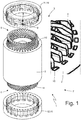
- the number 1 indicates as a whole a stator of a reversible synchronous automotive electric machine (i.e. that can work both as an electric motor by absorbing electrical energy and generating a mechanical driving torque and as an electric generator by absorbing mechanical energy and generating electrical energy).
- the stator 1 has a cylindrical tubular shape and is arranged around a rotor (not shown) to enclose the rotor.
- the rotor might be arranged externally with respect to stator 1, or the stator 1 might not have a cylindrical shape.
- the stator 1 comprises a magnetic core 2, which is formed by a series of pack-tightened sheets and has a cylindrical centrally holed shape (i.e. a tubular shape).
- the magnetic core 2 has two circular opposite base walls and is longitudinally crossed by a plurality of slots, which are evenly distributed along the inner side of the magnetic core 2, each of them extending from a base wall to the opposite base wall.
- a three-phase winding 3 is coupled to the magnetic core 2, which comprises a series of rigid bars 4 that are mutually connected to form the electrical paths of the stator winding 3 at the two heads 5 and 6. This means that the bars 4 form the electrical conductors of the stator winding 3. According to other embodiments not shown, the winding could have a number of phases different from three.
- Each bar 4 has a straight portion inserted in a respective slot of the magnetic core 2 and two curved portions, which are arranged out of the magnetic core 2, are mutually opposite and are part of the corresponding heads 5 and 6 of the winding 3.
- each bar 4 is initially U-shaped and comprises two legs connected by a cusp.
- the two legs of the same bar 4 form two corresponding conductors of the stator winding 3.
- the U-shaped bars 4 are inserted through the stator slots, defining an inlet side (at the heads 5) in which the cusps of the U-shaped bars 4 are arranged, and an outlet side (at the heads 6) in which the legs of the U-shaped bars 4 are arranged.
- the ends of the legs of the U-shaped bars 4 arranged in the outlet side are (differently) bent and are therefore electrically connected by welding to form the electrical paths of the stator winding 3 (and therefore to make up the head 6 of the winding 3).
- the stator 1 comprises a cooling circuit 7, which is designed to be flown through by a cooling fluid (typically water, possibly added with anti-freeze additives and/or with anti-corrosion additives) and has an inlet opening 8 of the cooling fluid and an outlet opening 9 of the cooling fluid.
- the cooling circuit 7 coupled to the stator 1 is part of a cooling system, which further comprises a circulation pump (not shown) and a radiator (not shown, i.e. a water/air heat exchanger). In use, the cooling system circulates the cooling fluid through the cooling circuit 7 coupled to the stator 1 and through the radiator so as to remove heat from the stator 1.
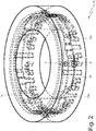
- the cooling circuit 7 comprises a plurality of main channels 10, which are formed inside the magnetic core 2 beside, and radially more on the outside than the slots containing the bars 4, each of them extending from a base wall to the opposite base wall. Moreover, the cooling circuit 7 comprises a pair of end bodies 11 and 12, each of which rests in a fluid-tight manner against a corresponding base of the magnetic core 2, is arranged around a corresponding head 5 or 6 of the winding and contains a series of joining channels 13, which are connected to the ends of the main channels 10 leading into the corresponding base of the magnetic core.
- annular manifold 14 that is closed on itself (i.e., extends over 360° with no beginning and no end), is coaxial with the magnetic core 2 and is connected to the inlet opening 8 of the cooling fluid
- annular manifold 15 that is closed on itself (i.e., extends over 360° with no beginning and no end) is coaxial to the magnetic core 2 and is connected to the outlet opening 9 of the cooling fluid.
- both annular manifolds 14 and 15 are formed in the same end body 11 and are axially arranged one on top of the other (namely are axially spaced apart).
- some joining channels 13a are straight, are axially arranged (i.e. are parallel to a central axis of symmetry of the magnetic core 2), and connect annular manifolds 14 and 15 to corresponding main channels 10.
- other joining channels 13b are U-shaped, are insulated from the annular manifolds 14 and 15 and each of them connects two main channels 10 (i.e. each joining channel 13b connects the ends of two main channels 10).
- the end body 11 has straight joining channels 13a and U-shaped joining channels 13b, whereas the end body 12 only has U-shaped joining channels 13b (i.e. all joining channels 13b formed in the end body 12 are U-shaped and each of them connects two main channels 10).
- the stator 1 comprises two crowns 16 (also called “pottings") made of plastic material (in particular of thermosetting and waterproof resin), each of which encloses a corresponding head 5 or 6 of the winding 3.
- each crown 16 is a resin coating that covers and encloses a corresponding head 5 or 6 of the winding 3 to form an electrical insulation and an insulation against the atmospheric agents of the head 5 or 6 of the winding 3
- the crowns 16 are made of a plastic material that is electrically insulating and thermally conductive.
- the two end bodies 11 and 12 are formed by the two crowns 16 containing the joining channels 13.
- the two end bodies 11 and 12 are integrated in the two crowns 16 and therefore coincide with the two crowns 16.
- the joining channels 13 and the annular manifolds 14 and 15 can be formed in the end bodies 11 and 12 by curing the resin constituting the crowns 16 in a mould provided with disposable cores (e.g. made of wax).
- the disposable cores prevent the plastic material constituting the crowns 16 from penetrating into the main channels 10, thus plugging the main channels 10.
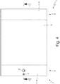
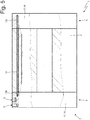
- each end body 11 or 12 is separated from the corresponding crown 16 and is arranged around (namely radially outwardly) the crown 16.
- the end body 12 is composed of a single indivisible piece, whereas the end body 11 is composed of two pieces 11a and 11b (shown in Figures 7 and 8 ), initially distinct and then joined to one another.
- the end bodies 11 and 12 could be manufactured in different ways.
- the end bodies 11 and 12 could both be formed by two semi-cylinders that are connected to each other (e.g. by means of screws) to make their assembly on the magnetic core 2 easier.
- annular insulating sheet 17 (preferably, but not necessarily made of a ceramic material) is arranged between each end body 11 or 12 and the corresponding crown 16.
- the insulating sheet 17 should be made of an electrically insulating and thermally conductive material.
- each insulating sheet 17 is connected in a fluid-tight manner to the corresponding end body 11 or 12 and constitutes an inner wall of the joining channels 13 and/or of the annular manifolds 14 and 15 of the corresponding end body 11 or 12.
- the joining channels 13 and/or the annular manifolds 14 and 15 are formed inside the end bodies 11 and 12 and therefore each insulating sheet 17 simply rests (without any fluid-tight connection) against the corresponding end body 11 or 12; in this embodiment, insulating sheets 17 may also be absent.
- the end bodies 11 and 12 can be made of a metal material (e.g. aluminium) or of a plastic material.
- the joining channels 13 and the annular manifolds 14 and 15 can be formed in the end bodies 11 and 12 by casting in a mould provided with disposable cores and/or by mechanical machining with chip removal.
- both annular manifolds 14 and 15 are formed in the same end body 11. This solution allows obtaining an optimal temperature distribution, but on the other hand has a more complicated manufacturing (since the two annular manifolds 14 and 15 must be very close together).
- annular manifold 14 is formed in the end body 11 and the annular manifold 15 is formed in the end body 12 opposite the end body 11.
- This solution is of simpler realization, but on the other hand it does not allow obtaining an optimal temperature distribution.
- all joining channels 13 are straight, are axially arranged and connect annular manifolds 14 and 15 to corresponding main channels 10.
- some joining channels 13a are straight, are axially arranged and connect the annular manifolds 14 and 15 to corresponding main channels 10, whereas other joining channels 13b are U-shaped, are insulated from the annular manifolds 14 and 15 and each of them connects two main channels 10 (i.e. each joining channel 13b connects the ends of two main channels 10) .
- the main channels 10 may be provided in advance with an impermeable coating to prevent the cooling fluid flowing in the main channels 10 from creeping between the sheets of the magnetic core 2 until they reach the bars 4 (i.e. the live conductors in which the electric current flows).
- the function of the impermeable coating of the main channels 10 is to guarantee a clear separation between the cooling fluid and the bars 4 (i.e. the conductors under tension in which the electric current flows).
- This impermeable coating can be applied to the main channels 10 by painting the main channels 10 using an impermeable varnish or enamel.
- the main channels 10 formed in the sheets of the magnetic core 2 are sealed to each other and made impermeable by using special sealing varnishes/enamels, which can be applied by spraying or by immersion. This prevents the cooling fluid from creeping between one sheet and the other until reaching the bars 4 (namely, the live conductors in which the electric current flows).
- the winding 3 of the stator 1 is formed by rigid bars 4, i.e. it is a "bar winding".
- the winding 3 of the stator 1 is made by a round wire that is wound in coils inserted in the slots of the stator, i.e. it is a "wire winding".
- the aforementioned stator 1 has several advantages.
- the aforementioned stator 1 provides an extremely efficient cooling, namely it provides particularly high thermal performances, since it allows minimizing the thermal resistance (and consequently the temperature difference) between the cooling fluid and the electrical conductors (namely the bars 4 of the winding 3) of the stator 1 and since it guarantees a very high amount of disposed heat per unit of volume of circulated cooling fluid.
- stator 1 described above is easy and inexpensive to manufacture, since the making of the main channels 10 inside the magnetic core 2 can be very simply achieved during the shearing of the sheets making up the magnetic core 2 and since the making of the end bodies 11 and 12 can be very simply achieved by means of disposable cores (end bodies 11 and 12 integrated in the crowns 16 as shown in Figures 1-5 ) or by trivial mechanical machining of annular elements (end bodies 11 and 12 separated by crowns 16 as shown in Figures 6-9 ).
Applications Claiming Priority (1)
| Application Number | Priority Date | Filing Date | Title |
|---|---|---|---|
| IT201700143710 | 2017-12-13 |
Publications (3)
| Publication Number | Publication Date |
|---|---|
| EP3499685A2 true EP3499685A2 (fr) | 2019-06-19 |
| EP3499685A3 EP3499685A3 (fr) | 2019-08-14 |
| EP3499685B1 EP3499685B1 (fr) | 2021-10-20 |
Family
ID=61952772
Family Applications (1)
| Application Number | Title | Priority Date | Filing Date |
|---|---|---|---|
| EP18211825.7A Active EP3499685B1 (fr) | 2017-12-13 | 2018-12-12 | Stator de machine électrique à refroidissement par fluide |
Country Status (2)
| Country | Link |
|---|---|
| US (1) | US10797542B2 (fr) |
| EP (1) | EP3499685B1 (fr) |
Cited By (5)
| Publication number | Priority date | Publication date | Assignee | Title |
|---|---|---|---|---|
| CN110808645A (zh) * | 2019-11-04 | 2020-02-18 | 合肥巨一动力系统有限公司 | 一种应用于油冷扁线电机定子的冷却结构 |
| CN112366881A (zh) * | 2020-10-14 | 2021-02-12 | 杭州乔纳森机电科技有限公司 | 内循环散热恒温电机壳体及具有该壳体的电机 |
| WO2021078458A1 (fr) * | 2019-10-21 | 2021-04-29 | Zf Friedrichshafen Ag | Stator pour une machine électrique |
| WO2023066648A1 (fr) * | 2021-10-19 | 2023-04-27 | Bayerische Motoren Werke Aktiengesellschaft | Stator pour une machine électrique d'un véhicule automobile et machine électrique |
| EP4307531A1 (fr) * | 2022-07-12 | 2024-01-17 | IFP Energies nouvelles | Machine électrique avec canal de refroidissement dans le matériau d'enrobage des têtes de bobines |
Families Citing this family (7)
| Publication number | Priority date | Publication date | Assignee | Title |
|---|---|---|---|---|
| JP6658627B2 (ja) * | 2017-03-10 | 2020-03-04 | トヨタ自動車株式会社 | 回転電機 |
| CN112564338A (zh) * | 2019-09-26 | 2021-03-26 | 广州汽车集团股份有限公司 | 驱动电机冷却结构、驱动电机及汽车 |
| CN110994820B (zh) * | 2019-12-30 | 2021-08-31 | 河南师范大学 | 一种水冷机壳和定子铁芯的装配结构及制造方法 |
| EP4085514A1 (fr) * | 2019-12-31 | 2022-11-09 | Mavel EDT S.p.A. | Procédé de fabrication d'un conducteur électrique pour un enroulement d'une machine électrique, conducteur électrique fabriqué par un tel procédé, et machine électrique comprenant un enroulement fabriqué avec un tel conducteur électrique |
| US11876405B2 (en) | 2020-01-14 | 2024-01-16 | Hamilton Sundstrand Corporation | Electric motor with cooling channels |
| US20220209594A1 (en) * | 2020-12-30 | 2022-06-30 | Volvo Car Corporation | Stator cooling for electric machines |
| DE102022121880B4 (de) * | 2022-08-30 | 2024-03-28 | Schaeffler Technologies AG & Co. KG | Stator |
Citations (4)
| Publication number | Priority date | Publication date | Assignee | Title |
|---|---|---|---|---|
| EP2112744A1 (fr) | 2008-04-24 | 2009-10-28 | Magneti Marelli Holding S.p.A. | Machine synchrone polyphasée pour convertir l'énergie cinétique en énergie électrique et l'énergie électrique en une énergie cinétique à bord d'un véhicule de transport, et véhicule de transport comprenant cette machine électrique |
| DE102008049226A1 (de) | 2008-09-27 | 2010-04-01 | Daimler Ag | Vorrichtung zur Kühlung eines Stators |
| US20110285221A1 (en) | 2010-05-21 | 2011-11-24 | Remy Technologies, L.L.C. | Stator Winding Assembly and Method |
| US20130076171A1 (en) | 2011-09-23 | 2013-03-28 | Attila Lepres | Electric machine module cooling system and method |
Family Cites Families (10)
| Publication number | Priority date | Publication date | Assignee | Title |
|---|---|---|---|---|
| GB1128194A (en) * | 1966-05-11 | 1968-09-25 | Ass Elect Ind | Improvements in or relating to dynamo-electric machines |
| US5806169A (en) * | 1995-04-03 | 1998-09-15 | Trago; Bradley A. | Method of fabricating an injected molded motor assembly |
| SE9703557D0 (sv) * | 1997-09-30 | 1997-09-30 | Asea Brown Boveri | Förfarande för applicering av ett kylrör i en kylrörskanal |
| KR20010034382A (ko) * | 1998-01-26 | 2001-04-25 | 칼 하인쯔 호르닝어 | 제너레이터의 냉각을 위한 냉각 시스템 및 방법 |
| DE102012022453A1 (de) * | 2012-11-09 | 2014-05-15 | Getrag Getriebe- Und Zahnradfabrik Hermann Hagenmeyer Gmbh & Cie Kg | Elektrische Maschine und Kraftfahrzeug-Antriebsstrang |
| DE102012022481A1 (de) | 2012-11-19 | 2014-05-22 | Sew-Eurodrive Gmbh & Co Kg | Elektromotor mit einem Stator |
| US9419479B2 (en) * | 2013-03-14 | 2016-08-16 | Baldor Electric Company | Micro-channel heat exchanger for stator of electrical machine with supply header |
| US10770953B2 (en) * | 2013-04-03 | 2020-09-08 | Lcdrives Corp. | Liquid cooled stator for high efficiency machine |
| ITMI20131548A1 (it) | 2013-09-19 | 2015-03-20 | Wilic Sarl | Statore di una macchina elettrica rotante di un aerogeneratore |
| JP2016059117A (ja) | 2014-09-08 | 2016-04-21 | 住友重機械工業株式会社 | リニアモータ用電機子 |
-
2018
- 2018-12-12 EP EP18211825.7A patent/EP3499685B1/fr active Active
- 2018-12-12 US US16/217,117 patent/US10797542B2/en active Active
Patent Citations (4)
| Publication number | Priority date | Publication date | Assignee | Title |
|---|---|---|---|---|
| EP2112744A1 (fr) | 2008-04-24 | 2009-10-28 | Magneti Marelli Holding S.p.A. | Machine synchrone polyphasée pour convertir l'énergie cinétique en énergie électrique et l'énergie électrique en une énergie cinétique à bord d'un véhicule de transport, et véhicule de transport comprenant cette machine électrique |
| DE102008049226A1 (de) | 2008-09-27 | 2010-04-01 | Daimler Ag | Vorrichtung zur Kühlung eines Stators |
| US20110285221A1 (en) | 2010-05-21 | 2011-11-24 | Remy Technologies, L.L.C. | Stator Winding Assembly and Method |
| US20130076171A1 (en) | 2011-09-23 | 2013-03-28 | Attila Lepres | Electric machine module cooling system and method |
Cited By (7)
| Publication number | Priority date | Publication date | Assignee | Title |
|---|---|---|---|---|
| WO2021078458A1 (fr) * | 2019-10-21 | 2021-04-29 | Zf Friedrichshafen Ag | Stator pour une machine électrique |
| CN110808645A (zh) * | 2019-11-04 | 2020-02-18 | 合肥巨一动力系统有限公司 | 一种应用于油冷扁线电机定子的冷却结构 |
| CN110808645B (zh) * | 2019-11-04 | 2021-11-12 | 合肥巨一动力系统有限公司 | 一种应用于油冷扁线电机定子的冷却结构 |
| CN112366881A (zh) * | 2020-10-14 | 2021-02-12 | 杭州乔纳森机电科技有限公司 | 内循环散热恒温电机壳体及具有该壳体的电机 |
| WO2023066648A1 (fr) * | 2021-10-19 | 2023-04-27 | Bayerische Motoren Werke Aktiengesellschaft | Stator pour une machine électrique d'un véhicule automobile et machine électrique |
| EP4307531A1 (fr) * | 2022-07-12 | 2024-01-17 | IFP Energies nouvelles | Machine électrique avec canal de refroidissement dans le matériau d'enrobage des têtes de bobines |
| FR3138018A1 (fr) * | 2022-07-12 | 2024-01-19 | IFP Energies Nouvelles | Machine électrique avec canal de refroidissement dans le matériau d’enrobage des têtes de bobines |
Also Published As
| Publication number | Publication date |
|---|---|
| EP3499685B1 (fr) | 2021-10-20 |
| EP3499685A3 (fr) | 2019-08-14 |
| US20190207439A1 (en) | 2019-07-04 |
| US10797542B2 (en) | 2020-10-06 |
Similar Documents
| Publication | Publication Date | Title |
|---|---|---|
| EP3499685B1 (fr) | Stator de machine électrique à refroidissement par fluide | |
| US8247933B2 (en) | Methods and apparatus for a permanent magnet machine with a direct liquid cooled stator | |
| CN109936226B (zh) | 定子和带有冷却系统的电机 | |
| US9099900B2 (en) | Electric machine module cooling system and method | |
| US9768666B2 (en) | External cooling tube arrangement for a stator of an electric motor | |
| EP2571146A2 (fr) | Système de refroidissement de module de machine électrique et méthode de fabrication | |
| ES2312387T3 (es) | Estator de maquina electrica giratoria. | |
| US11387725B2 (en) | Integrated heat dissipative structure for electric machine | |
| CN104079096B (zh) | 定子、设置有该定子的旋转电机、以及该定子的制造方法 | |
| EP3163717A1 (fr) | Stator de moteur électrique et structure de refroidissement pour machine dynamo-électrique | |
| US8624452B2 (en) | Electric machine module cooling system and method | |
| US11043875B2 (en) | Temperature control assembly for an electric machine | |
| US8975792B2 (en) | Electric machine module cooling system and method | |
| KR20190059231A (ko) | 전기 모터 및 고정자 냉각 장치 | |
| CN115995903A (zh) | 用于机动车电机的定子的冷却装置、定子以及机动车 | |
| EP2605381A2 (fr) | Système de refroidissement de module de machine électrique et procédé | |
| US20130076171A1 (en) | Electric machine module cooling system and method | |
| US20130076167A1 (en) | Cooling system and method for electronic machines | |
| JP2004180498A (ja) | 巻き線冷却及びスロット充填が最適化された、集中巻きコイル式電動モーター | |
| EP3488515B1 (fr) | Moteur électrique | |
| CN110867993A (zh) | 电动马达的环形定子 | |
| JP2023011636A (ja) | 減速機用ケーシングを備えた回転電気機械 | |
| JP2010514406A (ja) | 多相回転電気機械のステータ、このステータを有する多相回転電気機械、およびこのステータの製造方法 | |
| KR20130137087A (ko) | 전기 기계 모듈 냉각 시스템 및 방법 | |
| WO2013012701A2 (fr) | Module de machine électrique |
Legal Events
| Date | Code | Title | Description |
|---|---|---|---|
| PUAI | Public reference made under article 153(3) epc to a published international application that has entered the european phase |
Free format text: ORIGINAL CODE: 0009012 |
|
| STAA | Information on the status of an ep patent application or granted ep patent |
Free format text: STATUS: THE APPLICATION HAS BEEN PUBLISHED |
|
| AK | Designated contracting states |
Kind code of ref document: A2 Designated state(s): AL AT BE BG CH CY CZ DE DK EE ES FI FR GB GR HR HU IE IS IT LI LT LU LV MC MK MT NL NO PL PT RO RS SE SI SK SM TR |
|
| AX | Request for extension of the european patent |
Extension state: BA ME |
|
| PUAL | Search report despatched |
Free format text: ORIGINAL CODE: 0009013 |
|
| AK | Designated contracting states |
Kind code of ref document: A3 Designated state(s): AL AT BE BG CH CY CZ DE DK EE ES FI FR GB GR HR HU IE IS IT LI LT LU LV MC MK MT NL NO PL PT RO RS SE SI SK SM TR |
|
| AX | Request for extension of the european patent |
Extension state: BA ME |
|
| RIC1 | Information provided on ipc code assigned before grant |
Ipc: H02K 1/16 20060101ALN20190709BHEP Ipc: H02K 9/19 20060101ALI20190709BHEP Ipc: H02K 1/20 20060101AFI20190709BHEP Ipc: H02K 3/12 20060101ALN20190709BHEP Ipc: H02K 3/38 20060101ALN20190709BHEP Ipc: H02K 5/20 20060101ALI20190709BHEP |
|
| STAA | Information on the status of an ep patent application or granted ep patent |
Free format text: STATUS: REQUEST FOR EXAMINATION WAS MADE |
|
| 17P | Request for examination filed |
Effective date: 20200213 |
|
| STAA | Information on the status of an ep patent application or granted ep patent |
Free format text: STATUS: EXAMINATION IS IN PROGRESS |
|
| 17Q | First examination report despatched |
Effective date: 20201208 |
|
| STAA | Information on the status of an ep patent application or granted ep patent |
Free format text: STATUS: EXAMINATION IS IN PROGRESS |
|
| GRAP | Despatch of communication of intention to grant a patent |
Free format text: ORIGINAL CODE: EPIDOSNIGR1 |
|
| STAA | Information on the status of an ep patent application or granted ep patent |
Free format text: STATUS: GRANT OF PATENT IS INTENDED |
|
| RIC1 | Information provided on ipc code assigned before grant |
Ipc: H02K 3/38 20060101ALN20210416BHEP Ipc: H02K 3/12 20060101ALN20210416BHEP Ipc: H02K 1/16 20060101ALN20210416BHEP Ipc: H02K 9/19 20060101ALI20210416BHEP Ipc: H02K 5/20 20060101ALI20210416BHEP Ipc: H02K 1/20 20060101AFI20210416BHEP |
|
| INTG | Intention to grant announced |
Effective date: 20210517 |
|
| RIC1 | Information provided on ipc code assigned before grant |
Ipc: H02K 3/38 20060101ALN20210504BHEP Ipc: H02K 3/12 20060101ALN20210504BHEP Ipc: H02K 1/16 20060101ALN20210504BHEP Ipc: H02K 9/19 20060101ALI20210504BHEP Ipc: H02K 5/20 20060101ALI20210504BHEP Ipc: H02K 1/20 20060101AFI20210504BHEP |
|
| GRAS | Grant fee paid |
Free format text: ORIGINAL CODE: EPIDOSNIGR3 |
|
| GRAA | (expected) grant |
Free format text: ORIGINAL CODE: 0009210 |
|
| STAA | Information on the status of an ep patent application or granted ep patent |
Free format text: STATUS: THE PATENT HAS BEEN GRANTED |
|
| AK | Designated contracting states |
Kind code of ref document: B1 Designated state(s): AL AT BE BG CH CY CZ DE DK EE ES FI FR GB GR HR HU IE IS IT LI LT LU LV MC MK MT NL NO PL PT RO RS SE SI SK SM TR |
|
| REG | Reference to a national code |
Ref country code: GB Ref legal event code: FG4D |
|
| REG | Reference to a national code |
Ref country code: CH Ref legal event code: EP |
|
| REG | Reference to a national code |
Ref country code: DE Ref legal event code: R096 Ref document number: 602018025247 Country of ref document: DE |
|
| REG | Reference to a national code |
Ref country code: IE Ref legal event code: FG4D |
|
| REG | Reference to a national code |
Ref country code: AT Ref legal event code: REF Ref document number: 1440732 Country of ref document: AT Kind code of ref document: T Effective date: 20211115 |
|
| REG | Reference to a national code |
Ref country code: LT Ref legal event code: MG9D |
|
| REG | Reference to a national code |
Ref country code: NL Ref legal event code: MP Effective date: 20211020 |
|
| REG | Reference to a national code |
Ref country code: AT Ref legal event code: MK05 Ref document number: 1440732 Country of ref document: AT Kind code of ref document: T Effective date: 20211020 |
|
| PG25 | Lapsed in a contracting state [announced via postgrant information from national office to epo] |
Ref country code: RS Free format text: LAPSE BECAUSE OF FAILURE TO SUBMIT A TRANSLATION OF THE DESCRIPTION OR TO PAY THE FEE WITHIN THE PRESCRIBED TIME-LIMIT Effective date: 20211020 Ref country code: LT Free format text: LAPSE BECAUSE OF FAILURE TO SUBMIT A TRANSLATION OF THE DESCRIPTION OR TO PAY THE FEE WITHIN THE PRESCRIBED TIME-LIMIT Effective date: 20211020 Ref country code: FI Free format text: LAPSE BECAUSE OF FAILURE TO SUBMIT A TRANSLATION OF THE DESCRIPTION OR TO PAY THE FEE WITHIN THE PRESCRIBED TIME-LIMIT Effective date: 20211020 Ref country code: BG Free format text: LAPSE BECAUSE OF FAILURE TO SUBMIT A TRANSLATION OF THE DESCRIPTION OR TO PAY THE FEE WITHIN THE PRESCRIBED TIME-LIMIT Effective date: 20220120 Ref country code: AT Free format text: LAPSE BECAUSE OF FAILURE TO SUBMIT A TRANSLATION OF THE DESCRIPTION OR TO PAY THE FEE WITHIN THE PRESCRIBED TIME-LIMIT Effective date: 20211020 |
|
| PG25 | Lapsed in a contracting state [announced via postgrant information from national office to epo] |
Ref country code: IS Free format text: LAPSE BECAUSE OF FAILURE TO SUBMIT A TRANSLATION OF THE DESCRIPTION OR TO PAY THE FEE WITHIN THE PRESCRIBED TIME-LIMIT Effective date: 20220220 Ref country code: SE Free format text: LAPSE BECAUSE OF FAILURE TO SUBMIT A TRANSLATION OF THE DESCRIPTION OR TO PAY THE FEE WITHIN THE PRESCRIBED TIME-LIMIT Effective date: 20211020 Ref country code: PT Free format text: LAPSE BECAUSE OF FAILURE TO SUBMIT A TRANSLATION OF THE DESCRIPTION OR TO PAY THE FEE WITHIN THE PRESCRIBED TIME-LIMIT Effective date: 20220221 Ref country code: PL Free format text: LAPSE BECAUSE OF FAILURE TO SUBMIT A TRANSLATION OF THE DESCRIPTION OR TO PAY THE FEE WITHIN THE PRESCRIBED TIME-LIMIT Effective date: 20211020 Ref country code: NO Free format text: LAPSE BECAUSE OF FAILURE TO SUBMIT A TRANSLATION OF THE DESCRIPTION OR TO PAY THE FEE WITHIN THE PRESCRIBED TIME-LIMIT Effective date: 20220120 Ref country code: NL Free format text: LAPSE BECAUSE OF FAILURE TO SUBMIT A TRANSLATION OF THE DESCRIPTION OR TO PAY THE FEE WITHIN THE PRESCRIBED TIME-LIMIT Effective date: 20211020 Ref country code: LV Free format text: LAPSE BECAUSE OF FAILURE TO SUBMIT A TRANSLATION OF THE DESCRIPTION OR TO PAY THE FEE WITHIN THE PRESCRIBED TIME-LIMIT Effective date: 20211020 Ref country code: HR Free format text: LAPSE BECAUSE OF FAILURE TO SUBMIT A TRANSLATION OF THE DESCRIPTION OR TO PAY THE FEE WITHIN THE PRESCRIBED TIME-LIMIT Effective date: 20211020 Ref country code: GR Free format text: LAPSE BECAUSE OF FAILURE TO SUBMIT A TRANSLATION OF THE DESCRIPTION OR TO PAY THE FEE WITHIN THE PRESCRIBED TIME-LIMIT Effective date: 20220121 Ref country code: ES Free format text: LAPSE BECAUSE OF FAILURE TO SUBMIT A TRANSLATION OF THE DESCRIPTION OR TO PAY THE FEE WITHIN THE PRESCRIBED TIME-LIMIT Effective date: 20211020 |
|
| REG | Reference to a national code |
Ref country code: DE Ref legal event code: R097 Ref document number: 602018025247 Country of ref document: DE |
|
| PG25 | Lapsed in a contracting state [announced via postgrant information from national office to epo] |
Ref country code: SM Free format text: LAPSE BECAUSE OF FAILURE TO SUBMIT A TRANSLATION OF THE DESCRIPTION OR TO PAY THE FEE WITHIN THE PRESCRIBED TIME-LIMIT Effective date: 20211020 Ref country code: SK Free format text: LAPSE BECAUSE OF FAILURE TO SUBMIT A TRANSLATION OF THE DESCRIPTION OR TO PAY THE FEE WITHIN THE PRESCRIBED TIME-LIMIT Effective date: 20211020 Ref country code: RO Free format text: LAPSE BECAUSE OF FAILURE TO SUBMIT A TRANSLATION OF THE DESCRIPTION OR TO PAY THE FEE WITHIN THE PRESCRIBED TIME-LIMIT Effective date: 20211020 Ref country code: MC Free format text: LAPSE BECAUSE OF FAILURE TO SUBMIT A TRANSLATION OF THE DESCRIPTION OR TO PAY THE FEE WITHIN THE PRESCRIBED TIME-LIMIT Effective date: 20211020 Ref country code: EE Free format text: LAPSE BECAUSE OF FAILURE TO SUBMIT A TRANSLATION OF THE DESCRIPTION OR TO PAY THE FEE WITHIN THE PRESCRIBED TIME-LIMIT Effective date: 20211020 Ref country code: DK Free format text: LAPSE BECAUSE OF FAILURE TO SUBMIT A TRANSLATION OF THE DESCRIPTION OR TO PAY THE FEE WITHIN THE PRESCRIBED TIME-LIMIT Effective date: 20211020 Ref country code: CZ Free format text: LAPSE BECAUSE OF FAILURE TO SUBMIT A TRANSLATION OF THE DESCRIPTION OR TO PAY THE FEE WITHIN THE PRESCRIBED TIME-LIMIT Effective date: 20211020 |
|
| REG | Reference to a national code |
Ref country code: CH Ref legal event code: PL |
|
| PLBE | No opposition filed within time limit |
Free format text: ORIGINAL CODE: 0009261 |
|
| STAA | Information on the status of an ep patent application or granted ep patent |
Free format text: STATUS: NO OPPOSITION FILED WITHIN TIME LIMIT |
|
| REG | Reference to a national code |
Ref country code: BE Ref legal event code: MM Effective date: 20211231 |
|
| 26N | No opposition filed |
Effective date: 20220721 |
|
| PG25 | Lapsed in a contracting state [announced via postgrant information from national office to epo] |
Ref country code: LU Free format text: LAPSE BECAUSE OF NON-PAYMENT OF DUE FEES Effective date: 20211212 Ref country code: IE Free format text: LAPSE BECAUSE OF NON-PAYMENT OF DUE FEES Effective date: 20211212 Ref country code: AL Free format text: LAPSE BECAUSE OF FAILURE TO SUBMIT A TRANSLATION OF THE DESCRIPTION OR TO PAY THE FEE WITHIN THE PRESCRIBED TIME-LIMIT Effective date: 20211020 |
|
| PG25 | Lapsed in a contracting state [announced via postgrant information from national office to epo] |
Ref country code: SI Free format text: LAPSE BECAUSE OF FAILURE TO SUBMIT A TRANSLATION OF THE DESCRIPTION OR TO PAY THE FEE WITHIN THE PRESCRIBED TIME-LIMIT Effective date: 20211020 Ref country code: BE Free format text: LAPSE BECAUSE OF NON-PAYMENT OF DUE FEES Effective date: 20211231 |
|
| PG25 | Lapsed in a contracting state [announced via postgrant information from national office to epo] |
Ref country code: LI Free format text: LAPSE BECAUSE OF NON-PAYMENT OF DUE FEES Effective date: 20211231 Ref country code: CH Free format text: LAPSE BECAUSE OF NON-PAYMENT OF DUE FEES Effective date: 20211231 |
|
| PGFP | Annual fee paid to national office [announced via postgrant information from national office to epo] |
Ref country code: DE Payment date: 20221227 Year of fee payment: 5 |
|
| PG25 | Lapsed in a contracting state [announced via postgrant information from national office to epo] |
Ref country code: CY Free format text: LAPSE BECAUSE OF FAILURE TO SUBMIT A TRANSLATION OF THE DESCRIPTION OR TO PAY THE FEE WITHIN THE PRESCRIBED TIME-LIMIT Effective date: 20211020 |
|
| P01 | Opt-out of the competence of the unified patent court (upc) registered |
Effective date: 20230525 |
|
| PG25 | Lapsed in a contracting state [announced via postgrant information from national office to epo] |
Ref country code: HU Free format text: LAPSE BECAUSE OF FAILURE TO SUBMIT A TRANSLATION OF THE DESCRIPTION OR TO PAY THE FEE WITHIN THE PRESCRIBED TIME-LIMIT; INVALID AB INITIO Effective date: 20181212 |
|
| PGFP | Annual fee paid to national office [announced via postgrant information from national office to epo] |
Ref country code: GB Payment date: 20231219 Year of fee payment: 6 |
|
| PGFP | Annual fee paid to national office [announced via postgrant information from national office to epo] |
Ref country code: IT Payment date: 20231130 Year of fee payment: 6 Ref country code: FR Payment date: 20231226 Year of fee payment: 6 |