EP3499685A2 - Stator of an electric machine provided with fluid cooling - Google Patents
Stator of an electric machine provided with fluid cooling Download PDFInfo
- Publication number
- EP3499685A2 EP3499685A2 EP18211825.7A EP18211825A EP3499685A2 EP 3499685 A2 EP3499685 A2 EP 3499685A2 EP 18211825 A EP18211825 A EP 18211825A EP 3499685 A2 EP3499685 A2 EP 3499685A2
- Authority
- EP
- European Patent Office
- Prior art keywords
- stator
- magnetic core
- channels
- winding
- end body
- Prior art date
- Legal status (The legal status is an assumption and is not a legal conclusion. Google has not performed a legal analysis and makes no representation as to the accuracy of the status listed.)
- Granted
Links
- 238000001816 cooling Methods 0.000 title claims abstract description 34
- 239000012530 fluid Substances 0.000 title description 4
- 238000004804 winding Methods 0.000 claims abstract description 35
- 238000005304 joining Methods 0.000 claims abstract description 33
- 239000012809 cooling fluid Substances 0.000 claims abstract description 32
- 239000004020 conductor Substances 0.000 claims description 18
- 239000000463 material Substances 0.000 claims description 7
- 239000004033 plastic Substances 0.000 claims description 7
- 239000011248 coating agent Substances 0.000 claims description 5
- 238000000576 coating method Methods 0.000 claims description 5
- 229910010293 ceramic material Inorganic materials 0.000 claims description 3
- 230000000284 resting effect Effects 0.000 claims 2
- 230000000694 effects Effects 0.000 description 4
- 241000005139 Lycium andersonii Species 0.000 description 3
- 238000009413 insulation Methods 0.000 description 3
- 238000004519 manufacturing process Methods 0.000 description 3
- 239000011347 resin Substances 0.000 description 3
- 229920005989 resin Polymers 0.000 description 3
- XLYOFNOQVPJJNP-UHFFFAOYSA-N water Substances O XLYOFNOQVPJJNP-UHFFFAOYSA-N 0.000 description 3
- 239000000654 additive Substances 0.000 description 2
- 210000003298 dental enamel Anatomy 0.000 description 2
- 238000009826 distribution Methods 0.000 description 2
- 238000003754 machining Methods 0.000 description 2
- 239000002966 varnish Substances 0.000 description 2
- 108010053481 Antifreeze Proteins Proteins 0.000 description 1
- 230000032683 aging Effects 0.000 description 1
- 239000004411 aluminium Substances 0.000 description 1
- 229910052782 aluminium Inorganic materials 0.000 description 1
- XAGFODPZIPBFFR-UHFFFAOYSA-N aluminium Chemical compound [Al] XAGFODPZIPBFFR-UHFFFAOYSA-N 0.000 description 1
- 230000002528 anti-freeze Effects 0.000 description 1
- 230000005540 biological transmission Effects 0.000 description 1
- 238000005266 casting Methods 0.000 description 1
- 239000003795 chemical substances by application Substances 0.000 description 1
- 238000005260 corrosion Methods 0.000 description 1
- 238000010292 electrical insulation Methods 0.000 description 1
- 238000007654 immersion Methods 0.000 description 1
- 230000010354 integration Effects 0.000 description 1
- 239000007769 metal material Substances 0.000 description 1
- 238000013021 overheating Methods 0.000 description 1
- 238000010422 painting Methods 0.000 description 1
- 230000003071 parasitic effect Effects 0.000 description 1
- 230000000149 penetrating effect Effects 0.000 description 1
- 238000004382 potting Methods 0.000 description 1
- 230000002035 prolonged effect Effects 0.000 description 1
- 230000002441 reversible effect Effects 0.000 description 1
- 238000007789 sealing Methods 0.000 description 1
- 238000000926 separation method Methods 0.000 description 1
- 238000010008 shearing Methods 0.000 description 1
- 238000005507 spraying Methods 0.000 description 1
- 230000001360 synchronised effect Effects 0.000 description 1
- 229920001187 thermosetting polymer Polymers 0.000 description 1
- 238000003466 welding Methods 0.000 description 1
Images


Classifications
-
- H—ELECTRICITY
- H02—GENERATION; CONVERSION OR DISTRIBUTION OF ELECTRIC POWER
- H02K—DYNAMO-ELECTRIC MACHINES
- H02K1/00—Details of the magnetic circuit
- H02K1/06—Details of the magnetic circuit characterised by the shape, form or construction
- H02K1/12—Stationary parts of the magnetic circuit
- H02K1/20—Stationary parts of the magnetic circuit with channels or ducts for flow of cooling medium
-
- H—ELECTRICITY
- H02—GENERATION; CONVERSION OR DISTRIBUTION OF ELECTRIC POWER
- H02K—DYNAMO-ELECTRIC MACHINES
- H02K3/00—Details of windings
- H02K3/46—Fastening of windings on the stator or rotor structure
- H02K3/50—Fastening of winding heads, equalising connectors, or connections thereto
-
- H—ELECTRICITY
- H02—GENERATION; CONVERSION OR DISTRIBUTION OF ELECTRIC POWER
- H02K—DYNAMO-ELECTRIC MACHINES
- H02K5/00—Casings; Enclosures; Supports
- H02K5/04—Casings or enclosures characterised by the shape, form or construction thereof
- H02K5/20—Casings or enclosures characterised by the shape, form or construction thereof with channels or ducts for flow of cooling medium
- H02K5/203—Casings or enclosures characterised by the shape, form or construction thereof with channels or ducts for flow of cooling medium specially adapted for liquids, e.g. cooling jackets
-
- H—ELECTRICITY
- H02—GENERATION; CONVERSION OR DISTRIBUTION OF ELECTRIC POWER
- H02K—DYNAMO-ELECTRIC MACHINES
- H02K9/00—Arrangements for cooling or ventilating
- H02K9/19—Arrangements for cooling or ventilating for machines with closed casing and closed-circuit cooling using a liquid cooling medium, e.g. oil
- H02K9/197—Arrangements for cooling or ventilating for machines with closed casing and closed-circuit cooling using a liquid cooling medium, e.g. oil in which the rotor or stator space is fluid-tight, e.g. to provide for different cooling media for rotor and stator
-
- H—ELECTRICITY
- H02—GENERATION; CONVERSION OR DISTRIBUTION OF ELECTRIC POWER
- H02K—DYNAMO-ELECTRIC MACHINES
- H02K1/00—Details of the magnetic circuit
- H02K1/06—Details of the magnetic circuit characterised by the shape, form or construction
- H02K1/12—Stationary parts of the magnetic circuit
- H02K1/16—Stator cores with slots for windings
-
- H—ELECTRICITY
- H02—GENERATION; CONVERSION OR DISTRIBUTION OF ELECTRIC POWER
- H02K—DYNAMO-ELECTRIC MACHINES
- H02K3/00—Details of windings
- H02K3/04—Windings characterised by the conductor shape, form or construction, e.g. with bar conductors
- H02K3/12—Windings characterised by the conductor shape, form or construction, e.g. with bar conductors arranged in slots
-
- H—ELECTRICITY
- H02—GENERATION; CONVERSION OR DISTRIBUTION OF ELECTRIC POWER
- H02K—DYNAMO-ELECTRIC MACHINES
- H02K3/00—Details of windings
- H02K3/32—Windings characterised by the shape, form or construction of the insulation
- H02K3/38—Windings characterised by the shape, form or construction of the insulation around winding heads, equalising connectors, or connections thereto
Definitions
- the present invention relates to a stator of an electric machine provided with fluid cooling.
- the patent application DE 102008049226A1 describes a cooling system of a vehicle electric machine.
- the cooling system comprises an outer shell that encloses the casing of the electric machine, thus defining around the casing an annular cooling chamber (namely a so-called “water-jacket”) flown through by a cooling fluid (typically water).
- a cooling fluid typically water
- the patent application EP 2112744A1 describes a cooling system of a vehicle electric machine.
- the electric machine comprises a cylindrical casing, which is formed by an outer cup-shaped shell and by an inner cup-shaped shell, contains the stator and is inserted in the outer shell to define, together with the outer shell, a cylindrical body closed on both sides.
- a cooling circuit (namely a so-called "water-jacket") is formed between the outer shell and the inner shell, said circuit developing in a spiral between an inlet opening and an outlet opening, both formed in a side wall of the outer shell.
- the patent application US 2013076171A1 and the patent application US 2011285221A1 disclose a stator of a rotating electric machine provided with a cooling circuit, which is designed to be flown through by a cooling fluid and has an inlet opening of the cooling fluid and an outlet opening of the cooling fluid.
- the cooling circuit comprises a plurality of main channels, which are formed inside the magnetic core, beside, and radially more on the outside than the slots containing the conductors, each of them extending from a base wall to the opposite base wall of the magnetic core.
- the cooling circuit comprises a pair of end bodies, each of which rests in a fluid-tight manner against a corresponding base of the magnetic core, is arranged around a corresponding head of the winding and contains a series of joining channels, which are connected to the ends of the main channels leading into the corresponding base of the magnetic core.
- the object of the present invention is to provide a stator of an electric machine provided with fluid cooling, which has high thermal performances and, at the same time, is simple and inexpensive to manufacture.
- the number 1 indicates as a whole a stator of a reversible synchronous automotive electric machine (i.e. that can work both as an electric motor by absorbing electrical energy and generating a mechanical driving torque and as an electric generator by absorbing mechanical energy and generating electrical energy).
- the stator 1 has a cylindrical tubular shape and is arranged around a rotor (not shown) to enclose the rotor.
- the rotor might be arranged externally with respect to stator 1, or the stator 1 might not have a cylindrical shape.
- the stator 1 comprises a magnetic core 2, which is formed by a series of pack-tightened sheets and has a cylindrical centrally holed shape (i.e. a tubular shape).
- the magnetic core 2 has two circular opposite base walls and is longitudinally crossed by a plurality of slots, which are evenly distributed along the inner side of the magnetic core 2, each of them extending from a base wall to the opposite base wall.
- a three-phase winding 3 is coupled to the magnetic core 2, which comprises a series of rigid bars 4 that are mutually connected to form the electrical paths of the stator winding 3 at the two heads 5 and 6. This means that the bars 4 form the electrical conductors of the stator winding 3. According to other embodiments not shown, the winding could have a number of phases different from three.
- Each bar 4 has a straight portion inserted in a respective slot of the magnetic core 2 and two curved portions, which are arranged out of the magnetic core 2, are mutually opposite and are part of the corresponding heads 5 and 6 of the winding 3.
- each bar 4 is initially U-shaped and comprises two legs connected by a cusp.
- the two legs of the same bar 4 form two corresponding conductors of the stator winding 3.
- the U-shaped bars 4 are inserted through the stator slots, defining an inlet side (at the heads 5) in which the cusps of the U-shaped bars 4 are arranged, and an outlet side (at the heads 6) in which the legs of the U-shaped bars 4 are arranged.
- the ends of the legs of the U-shaped bars 4 arranged in the outlet side are (differently) bent and are therefore electrically connected by welding to form the electrical paths of the stator winding 3 (and therefore to make up the head 6 of the winding 3).
- the stator 1 comprises a cooling circuit 7, which is designed to be flown through by a cooling fluid (typically water, possibly added with anti-freeze additives and/or with anti-corrosion additives) and has an inlet opening 8 of the cooling fluid and an outlet opening 9 of the cooling fluid.
- the cooling circuit 7 coupled to the stator 1 is part of a cooling system, which further comprises a circulation pump (not shown) and a radiator (not shown, i.e. a water/air heat exchanger). In use, the cooling system circulates the cooling fluid through the cooling circuit 7 coupled to the stator 1 and through the radiator so as to remove heat from the stator 1.
- the cooling circuit 7 comprises a plurality of main channels 10, which are formed inside the magnetic core 2 beside, and radially more on the outside than the slots containing the bars 4, each of them extending from a base wall to the opposite base wall. Moreover, the cooling circuit 7 comprises a pair of end bodies 11 and 12, each of which rests in a fluid-tight manner against a corresponding base of the magnetic core 2, is arranged around a corresponding head 5 or 6 of the winding and contains a series of joining channels 13, which are connected to the ends of the main channels 10 leading into the corresponding base of the magnetic core.
- annular manifold 14 that is closed on itself (i.e., extends over 360° with no beginning and no end), is coaxial with the magnetic core 2 and is connected to the inlet opening 8 of the cooling fluid
- annular manifold 15 that is closed on itself (i.e., extends over 360° with no beginning and no end) is coaxial to the magnetic core 2 and is connected to the outlet opening 9 of the cooling fluid.
- both annular manifolds 14 and 15 are formed in the same end body 11 and are axially arranged one on top of the other (namely are axially spaced apart).
- some joining channels 13a are straight, are axially arranged (i.e. are parallel to a central axis of symmetry of the magnetic core 2), and connect annular manifolds 14 and 15 to corresponding main channels 10.
- other joining channels 13b are U-shaped, are insulated from the annular manifolds 14 and 15 and each of them connects two main channels 10 (i.e. each joining channel 13b connects the ends of two main channels 10).
- the end body 11 has straight joining channels 13a and U-shaped joining channels 13b, whereas the end body 12 only has U-shaped joining channels 13b (i.e. all joining channels 13b formed in the end body 12 are U-shaped and each of them connects two main channels 10).
- the stator 1 comprises two crowns 16 (also called “pottings") made of plastic material (in particular of thermosetting and waterproof resin), each of which encloses a corresponding head 5 or 6 of the winding 3.
- each crown 16 is a resin coating that covers and encloses a corresponding head 5 or 6 of the winding 3 to form an electrical insulation and an insulation against the atmospheric agents of the head 5 or 6 of the winding 3
- the crowns 16 are made of a plastic material that is electrically insulating and thermally conductive.
- the two end bodies 11 and 12 are formed by the two crowns 16 containing the joining channels 13.
- the two end bodies 11 and 12 are integrated in the two crowns 16 and therefore coincide with the two crowns 16.
- the joining channels 13 and the annular manifolds 14 and 15 can be formed in the end bodies 11 and 12 by curing the resin constituting the crowns 16 in a mould provided with disposable cores (e.g. made of wax).
- the disposable cores prevent the plastic material constituting the crowns 16 from penetrating into the main channels 10, thus plugging the main channels 10.
- each end body 11 or 12 is separated from the corresponding crown 16 and is arranged around (namely radially outwardly) the crown 16.
- the end body 12 is composed of a single indivisible piece, whereas the end body 11 is composed of two pieces 11a and 11b (shown in Figures 7 and 8 ), initially distinct and then joined to one another.
- the end bodies 11 and 12 could be manufactured in different ways.
- the end bodies 11 and 12 could both be formed by two semi-cylinders that are connected to each other (e.g. by means of screws) to make their assembly on the magnetic core 2 easier.
- annular insulating sheet 17 (preferably, but not necessarily made of a ceramic material) is arranged between each end body 11 or 12 and the corresponding crown 16.
- the insulating sheet 17 should be made of an electrically insulating and thermally conductive material.
- each insulating sheet 17 is connected in a fluid-tight manner to the corresponding end body 11 or 12 and constitutes an inner wall of the joining channels 13 and/or of the annular manifolds 14 and 15 of the corresponding end body 11 or 12.
- the joining channels 13 and/or the annular manifolds 14 and 15 are formed inside the end bodies 11 and 12 and therefore each insulating sheet 17 simply rests (without any fluid-tight connection) against the corresponding end body 11 or 12; in this embodiment, insulating sheets 17 may also be absent.
- the end bodies 11 and 12 can be made of a metal material (e.g. aluminium) or of a plastic material.
- the joining channels 13 and the annular manifolds 14 and 15 can be formed in the end bodies 11 and 12 by casting in a mould provided with disposable cores and/or by mechanical machining with chip removal.
- both annular manifolds 14 and 15 are formed in the same end body 11. This solution allows obtaining an optimal temperature distribution, but on the other hand has a more complicated manufacturing (since the two annular manifolds 14 and 15 must be very close together).
- annular manifold 14 is formed in the end body 11 and the annular manifold 15 is formed in the end body 12 opposite the end body 11.
- This solution is of simpler realization, but on the other hand it does not allow obtaining an optimal temperature distribution.
- all joining channels 13 are straight, are axially arranged and connect annular manifolds 14 and 15 to corresponding main channels 10.
- some joining channels 13a are straight, are axially arranged and connect the annular manifolds 14 and 15 to corresponding main channels 10, whereas other joining channels 13b are U-shaped, are insulated from the annular manifolds 14 and 15 and each of them connects two main channels 10 (i.e. each joining channel 13b connects the ends of two main channels 10) .
- the main channels 10 may be provided in advance with an impermeable coating to prevent the cooling fluid flowing in the main channels 10 from creeping between the sheets of the magnetic core 2 until they reach the bars 4 (i.e. the live conductors in which the electric current flows).
- the function of the impermeable coating of the main channels 10 is to guarantee a clear separation between the cooling fluid and the bars 4 (i.e. the conductors under tension in which the electric current flows).
- This impermeable coating can be applied to the main channels 10 by painting the main channels 10 using an impermeable varnish or enamel.
- the main channels 10 formed in the sheets of the magnetic core 2 are sealed to each other and made impermeable by using special sealing varnishes/enamels, which can be applied by spraying or by immersion. This prevents the cooling fluid from creeping between one sheet and the other until reaching the bars 4 (namely, the live conductors in which the electric current flows).
- the winding 3 of the stator 1 is formed by rigid bars 4, i.e. it is a "bar winding".
- the winding 3 of the stator 1 is made by a round wire that is wound in coils inserted in the slots of the stator, i.e. it is a "wire winding".
- the aforementioned stator 1 has several advantages.
- the aforementioned stator 1 provides an extremely efficient cooling, namely it provides particularly high thermal performances, since it allows minimizing the thermal resistance (and consequently the temperature difference) between the cooling fluid and the electrical conductors (namely the bars 4 of the winding 3) of the stator 1 and since it guarantees a very high amount of disposed heat per unit of volume of circulated cooling fluid.
- stator 1 described above is easy and inexpensive to manufacture, since the making of the main channels 10 inside the magnetic core 2 can be very simply achieved during the shearing of the sheets making up the magnetic core 2 and since the making of the end bodies 11 and 12 can be very simply achieved by means of disposable cores (end bodies 11 and 12 integrated in the crowns 16 as shown in Figures 1-5 ) or by trivial mechanical machining of annular elements (end bodies 11 and 12 separated by crowns 16 as shown in Figures 6-9 ).
Landscapes
- Engineering & Computer Science (AREA)
- Power Engineering (AREA)
- Motor Or Generator Cooling System (AREA)
- Iron Core Of Rotating Electric Machines (AREA)
Abstract
Description
- This patent application claims priority from Italian patent application no.
102017000143710 filed on December 13, 2017 - The present invention relates to a stator of an electric machine provided with fluid cooling.
- In road vehicles, the electric drive together with the traditional thermal drive to achieve a hybrid drive is increasingly popular.
- The integration of an electric machine in a road vehicle requires an adequate cooling system dedicated to the electric machine to prevent the electric machine from overheating and in particular to avoid that the insulation of the conductors forming the stator winding exceeds the nominal working temperatures (a prolonged exceeding of the nominal working temperatures accelerates the aging of the insulation of the conductors constituting the stator winding and therefore determines an early wear of the electric machine).
- The patent application
DE 102008049226A1 describes a cooling system of a vehicle electric machine. The cooling system comprises an outer shell that encloses the casing of the electric machine, thus defining around the casing an annular cooling chamber (namely a so-called "water-jacket") flown through by a cooling fluid (typically water). - The patent application
EP 2112744A1 describes a cooling system of a vehicle electric machine. The electric machine comprises a cylindrical casing, which is formed by an outer cup-shaped shell and by an inner cup-shaped shell, contains the stator and is inserted in the outer shell to define, together with the outer shell, a cylindrical body closed on both sides. A cooling circuit (namely a so-called "water-jacket") is formed between the outer shell and the inner shell, said circuit developing in a spiral between an inlet opening and an outlet opening, both formed in a side wall of the outer shell. - The creation of a so-called "water-jacket" around the stator does not allow obtaining particularly high thermal performances (in particular, the temperature difference between the cooling fluid and the electrical conductors of the stator is relatively large), because the cooling fluid remains far from the electrical conductors of the stator where most of the heat develops by Joule effect, namely because there is a significant thermal resistance between the stator electrical conductors (i.e. the area where most of the heat develops by Joule effect) and the cooling fluid.
- The patent application
US 2013076171A1 and the patent applicationUS 2011285221A1 disclose a stator of a rotating electric machine provided with a cooling circuit, which is designed to be flown through by a cooling fluid and has an inlet opening of the cooling fluid and an outlet opening of the cooling fluid. The cooling circuit comprises a plurality of main channels, which are formed inside the magnetic core, beside, and radially more on the outside than the slots containing the conductors, each of them extending from a base wall to the opposite base wall of the magnetic core. Moreover, the cooling circuit comprises a pair of end bodies, each of which rests in a fluid-tight manner against a corresponding base of the magnetic core, is arranged around a corresponding head of the winding and contains a series of joining channels, which are connected to the ends of the main channels leading into the corresponding base of the magnetic core. - The object of the present invention is to provide a stator of an electric machine provided with fluid cooling, which has high thermal performances and, at the same time, is simple and inexpensive to manufacture.
- According to the present invention, it is provided a stator of an electric machine provided with fluid cooling, as claimed in the appended claims.
- The claims describe preferred embodiments of the present invention forming an integral part of the present disclosure.
- The present invention will now be described with reference to the annexed drawings showing an example of a nonlimiting embodiment, in which:
-
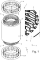
Figure 1 is a perspective view, exploded and with parts removed for clarity's sake, of a stator of an electric machine made in accordance with the present invention; -
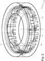
Figures 2 and3 are perspective views of two end bodies of a cooling circuit of the stator ofFigure 1 ; -
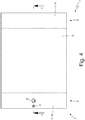
Figure 4 is a side view of the stator ofFigure 1 ; -
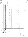
Figure 5 is a longitudinal section view along the section line V-V of the stator ofFigure 1 ; -
Figure 6 is a perspective view, exploded and with parts removed for clarity's sake, of an alternative embodiment of the stator ofFigure 1 ; -
Figures 7 ,8 and9 are perspective views of two end bodies of a cooling circuit of the stator ofFigure 6 ; -
Figure 10 is a schematic view of the flows of a cooling fluid in the stator ofFigure 1 ; and -
Figures 11 and12 are two schematic views of the flows of the cooling fluid in respective variants of the stator ofFigure 1 . - In
Figure 1 , thenumber 1 indicates as a whole a stator of a reversible synchronous automotive electric machine (i.e. that can work both as an electric motor by absorbing electrical energy and generating a mechanical driving torque and as an electric generator by absorbing mechanical energy and generating electrical energy). Thestator 1 has a cylindrical tubular shape and is arranged around a rotor (not shown) to enclose the rotor. According to other embodiments not shown, the rotor might be arranged externally with respect tostator 1, or thestator 1 might not have a cylindrical shape. - The
stator 1 comprises amagnetic core 2, which is formed by a series of pack-tightened sheets and has a cylindrical centrally holed shape (i.e. a tubular shape). Themagnetic core 2 has two circular opposite base walls and is longitudinally crossed by a plurality of slots, which are evenly distributed along the inner side of themagnetic core 2, each of them extending from a base wall to the opposite base wall. A three-phase winding 3 is coupled to themagnetic core 2, which comprises a series ofrigid bars 4 that are mutually connected to form the electrical paths of the stator winding 3 at the twoheads bars 4 form the electrical conductors of the stator winding 3. According to other embodiments not shown, the winding could have a number of phases different from three. - Each
bar 4 has a straight portion inserted in a respective slot of themagnetic core 2 and two curved portions, which are arranged out of themagnetic core 2, are mutually opposite and are part of thecorresponding heads winding 3. In particular, eachbar 4 is initially U-shaped and comprises two legs connected by a cusp. The two legs of thesame bar 4 form two corresponding conductors of the stator winding 3. TheU-shaped bars 4 are inserted through the stator slots, defining an inlet side (at the heads 5) in which the cusps of theU-shaped bars 4 are arranged, and an outlet side (at the heads 6) in which the legs of theU-shaped bars 4 are arranged. The ends of the legs of theU-shaped bars 4 arranged in the outlet side are (differently) bent and are therefore electrically connected by welding to form the electrical paths of the stator winding 3 (and therefore to make up thehead 6 of the winding 3). - The
stator 1 comprises acooling circuit 7, which is designed to be flown through by a cooling fluid (typically water, possibly added with anti-freeze additives and/or with anti-corrosion additives) and has an inlet opening 8 of the cooling fluid and an outlet opening 9 of the cooling fluid. Thecooling circuit 7 coupled to thestator 1 is part of a cooling system, which further comprises a circulation pump (not shown) and a radiator (not shown, i.e. a water/air heat exchanger). In use, the cooling system circulates the cooling fluid through thecooling circuit 7 coupled to thestator 1 and through the radiator so as to remove heat from thestator 1. - The
cooling circuit 7 comprises a plurality ofmain channels 10, which are formed inside themagnetic core 2 beside, and radially more on the outside than the slots containing thebars 4, each of them extending from a base wall to the opposite base wall. Moreover, thecooling circuit 7 comprises a pair ofend bodies magnetic core 2, is arranged around acorresponding head main channels 10 leading into the corresponding base of the magnetic core. - According to what better shown in
Figure 2 , it is provided anannular manifold 14 that is closed on itself (i.e., extends over 360° with no beginning and no end), is coaxial with themagnetic core 2 and is connected to the inlet opening 8 of the cooling fluid, and anannular manifold 15 that is closed on itself (i.e., extends over 360° with no beginning and no end), is coaxial to themagnetic core 2 and is connected to the outlet opening 9 of the cooling fluid. In the embodiment shown inFigure 2 , bothannular manifolds same end body 11 and are axially arranged one on top of the other (namely are axially spaced apart). - According to what better shown in
Figures 2 and3 , some joiningchannels 13a are straight, are axially arranged (i.e. are parallel to a central axis of symmetry of the magnetic core 2), and connectannular manifolds main channels 10. On the other hand, other joiningchannels 13b are U-shaped, are insulated from theannular manifolds channel 13b connects the ends of two main channels 10). In particular, in the embodiment shown inFigures 2 and3 in which bothannular manifolds same end body 11, theend body 11 has straight joiningchannels 13a and U-shapedjoining channels 13b, whereas theend body 12 only has U-shapedjoining channels 13b (i.e. all joiningchannels 13b formed in theend body 12 are U-shaped and each of them connects two main channels 10). - The
stator 1 comprises two crowns 16 (also called "pottings") made of plastic material (in particular of thermosetting and waterproof resin), each of which encloses acorresponding head winding 3. In other words, eachcrown 16 is a resin coating that covers and encloses acorresponding head head crowns 16 are made of a plastic material that is electrically insulating and thermally conductive. - In the embodiment shown in
Figures 1-5 , the twoend bodies crowns 16 containing the joining channels 13. In other words, the twoend bodies crowns 16 and therefore coincide with the twocrowns 16. In the embodiment shown inFigures 1-5 , the joining channels 13 and theannular manifolds end bodies crowns 16 in a mould provided with disposable cores (e.g. made of wax). Among other things, the disposable cores prevent the plastic material constituting thecrowns 16 from penetrating into themain channels 10, thus plugging themain channels 10. - According to a different embodiment shown in
Figures 6-9 , eachend body corresponding crown 16 and is arranged around (namely radially outwardly) thecrown 16. In particular, theend body 12 is composed of a single indivisible piece, whereas theend body 11 is composed of twopieces Figures 7 and8 ), initially distinct and then joined to one another. According to other embodiments not shown and perfectly equivalent, theend bodies end bodies magnetic core 2 easier. According to a preferred embodiment, an annular insulating sheet 17 (preferably, but not necessarily made of a ceramic material) is arranged between eachend body crown 16. As far as possible, the insulatingsheet 17 should be made of an electrically insulating and thermally conductive material. - According to the embodiment shown in
Figures 6-9 , the joining channels 13 and/or theannular manifolds end bodies 11 and 12 (namely the joining channels 13 and/or theannular manifolds end bodies 11 and 12). Moreover, each insulatingsheet 17 is connected in a fluid-tight manner to thecorresponding end body annular manifolds corresponding end body annular manifolds end bodies sheet 17 simply rests (without any fluid-tight connection) against thecorresponding end body sheets 17 may also be absent. - In the embodiment shown in
Figures 6-9 , theend bodies - In the embodiment shown in
Figures 6-9 , the joining channels 13 and theannular manifolds end bodies - In the embodiment shown in
Figures 1-10 , bothannular manifolds same end body 11. This solution allows obtaining an optimal temperature distribution, but on the other hand has a more complicated manufacturing (since the twoannular manifolds - In the alternative embodiment shown in
Figures 11 and12 , theannular manifold 14 is formed in theend body 11 and theannular manifold 15 is formed in theend body 12 opposite theend body 11. This solution is of simpler realization, but on the other hand it does not allow obtaining an optimal temperature distribution. In this case and as shown inFigure 11 , all joining channels 13 are straight, are axially arranged and connectannular manifolds main channels 10. Alternatively and as shown inFigure 12 , some joiningchannels 13a are straight, are axially arranged and connect theannular manifolds main channels 10, whereas other joiningchannels 13b are U-shaped, are insulated from theannular manifolds channel 13b connects the ends of two main channels 10) . - According to a possible embodiment, the
main channels 10 may be provided in advance with an impermeable coating to prevent the cooling fluid flowing in themain channels 10 from creeping between the sheets of themagnetic core 2 until they reach the bars 4 (i.e. the live conductors in which the electric current flows). In other words, the function of the impermeable coating of themain channels 10 is to guarantee a clear separation between the cooling fluid and the bars 4 (i.e. the conductors under tension in which the electric current flows). This impermeable coating can be applied to themain channels 10 by painting themain channels 10 using an impermeable varnish or enamel. In other words, themain channels 10 formed in the sheets of themagnetic core 2 are sealed to each other and made impermeable by using special sealing varnishes/enamels, which can be applied by spraying or by immersion. This prevents the cooling fluid from creeping between one sheet and the other until reaching the bars 4 (namely, the live conductors in which the electric current flows). - In the embodiment shown in the accompanying figures, the winding 3 of the
stator 1 is formed byrigid bars 4, i.e. it is a "bar winding". According to a different embodiment, not shown and perfectly equivalent, the winding 3 of thestator 1 is made by a round wire that is wound in coils inserted in the slots of the stator, i.e. it is a "wire winding". - The embodiments described herein can be combined without departing from the scope of protection of the present invention.
- The
aforementioned stator 1 has several advantages. - First, the
aforementioned stator 1 provides an extremely efficient cooling, namely it provides particularly high thermal performances, since it allows minimizing the thermal resistance (and consequently the temperature difference) between the cooling fluid and the electrical conductors (namely thebars 4 of the winding 3) of thestator 1 and since it guarantees a very high amount of disposed heat per unit of volume of circulated cooling fluid. These results are obtained thanks to the fact that themain channels 10 in which the cooling fluid flows are very close to thebars 4 in which the greatest part of the heat is generated by Joule effect and are directly formed in themagnetic core 2, thus allowing a maximum thermal exchange with the magnetic core 2 (i.e. the heat is removed directly where it is generated without having to wait for any heat transmission to elements outside the magnetic core 2). Moreover, these results are obtained thanks to the fact that the joining channels 13 and theannular manifolds heads heads magnetic core 2 of thestator 1 and is therefore very close (as close as possible) to the electrical conductors (namely to thebars 4 of the winding 3) of thestator 1 and this allows a better efficiency and a better continuous power. - Please note that in the
stator 1 described above, also the heat generated (essentially by the Joule effect of the parasitic currents) directly inside the sheets making up themagnetic core 2 is removed in an extremely effective and efficient manner. In fact, the cooling fluid flowing in themain channels 10 is substantially in direct contact with the sheets making up themagnetic core 2. - Moreover, the
stator 1 described above is easy and inexpensive to manufacture, since the making of themain channels 10 inside themagnetic core 2 can be very simply achieved during the shearing of the sheets making up themagnetic core 2 and since the making of theend bodies bodies crowns 16 as shown inFigures 1-5 ) or by trivial mechanical machining of annular elements (endbodies crowns 16 as shown inFigures 6-9 ). -
- 1 stator
- 2 magnetic core
- 3 stator winding
- 4 slot
- 5 head
- 6 head
- 7 cooling circuit
- 8 inlet opening
- 9 outlet opening
- 10 main channels
- 11 end body
- 12 end body
- 13 joining channels
- 14 annular manifold
- 15 annular manifold
- 16 crowns
- 17 insulating sheet
Claims (14)
- A stator (1) of an electric machine, wherein the stator (1) comprises:a magnetic core (2), which has two opposite base walls and is provided with a plurality of slots, each of them extending from a base wall to the opposite base wall;a winding (3), which is provided with a plurality of conductors, each having a straight segment, which is inserted in a respective slot of the magnetic core (2), and two curved segments, which are arranged on the outside of the magnetic core (2), are opposite one another and are part of two respective heads (5, 6) of the winding (3); anda cooling circuit (7), which is designed to be flown through by a cooling fluid and has an inlet opening (8) of the cooling fluid and an outlet opening (9) of the cooling fluid;wherein the cooling circuit (7) comprises a plurality of main channels (10), which are formed inside the magnetic core (2) beside, and radially more on the outside than the slots containing the conductors, each of them extending from a base wall to the opposite base wall;wherein the cooling circuit (7) comprises a pair of end bodies (11, 12), each resting against a corresponding base of the magnetic core (2) in a fluid-tight manner, being arranged around a corresponding head (5, 6) of the winding (3) and containing a series of joining channels (13), which are connected to the ends of the main channels (10) leading into the corresponding base of the magnetic core (2); andwherein the cooling circuit (7) comprises a first annular manifold (14), which is closed on itself, is arranged coaxially with the magnetic core (2) and is connected to the inlet opening (8) of the cooling fluid, and a second annular manifold (15), which is closed on itself, is arranged coaxially with the magnetic core (2) and is connected to the outlet opening (9) of the cooling fluid;the stator (1) being characterized in that both annular manifolds (14, 15) are formed in the same first end body (11) and are arranged axially one above the other.
- A stator (1) according to claim 1, wherein:there are two crowns (16) made of a plastic material, each enclosing a corresponding head (5, 6) of the winding (3); andthe two end bodies (11, 12) are formed by the two crowns (16) inside which the joining channels (13) are formed.
- A stator (1) according to claim 1, wherein:there are two crowns (16) made of a plastic material, each enclosing a corresponding head (5, 6) of the winding (3); andeach end body (11, 12) is separate from the corresponding crown (16) and is arranged around the crown (16) .
- A stator (1) according to claim 3, wherein an annular insulating sheet (17) is interposed between each end body (11, 12) and the corresponding crown (16).
- A stator (1) according to claim 4, wherein the insulating sheet (17) is made of a ceramic material.
- A stator (1) according to claim 4 or 5, wherein:the joining channels (13) are formed on an inner surface of the end bodies (11, 12); andeach insulating sheet (17) is connected to the corresponding end body (11, 12) in a fluid-tight manner and makes up an inner wall of the joining channels (13) of the corresponding end body (11, 12).
- A stator (1) according to any one of the claims from 1 to 6, wherein some joining channels (13a) are straight, are axially arranged and connect the annular manifolds (14, 15) to corresponding main channels (10).
- A stator (1) according to any one of the claims from 1 to 7, wherein some joining channels (13b) are u-shaped, are insulated from the annular manifolds (14, 15) and each of them connects two main channels (10).
- A stator (1) according to any one of the claims from 1 to 8, wherein all joining channels (13b) formed in a second end body (12), which is opposite the first end body (11), are u-shaped and each of them connects two main channels (10).
- A stator (1) according to any one of the claims from 1 to 9, wherein each main channel (10) is provided with an impermeable coating.
- A stator (1) of an electric machine; wherein the stator (1) comprises:a magnetic core (2), which has two mutually opposite base walls and is provided with a plurality of slots, each of them extending from a base wall to the opposite base wall;a winding (3) provided with a plurality of conductors, each of which has a straight portion inserted inside a respective slot of the magnetic core (2) and two curved portions that are arranged outside the magnetic core (2), are opposite to each other and are part of two corresponding heads (5, 6) of the winding (3); anda cooling circuit (7), which is designed to be flown through by a cooling fluid and has an inlet opening (8) of the cooling fluid and an outlet opening (9) of the cooling fluid;wherein the cooling circuit (7) comprises a plurality of main channels (10), which are formed inside the magnetic core (2) beside, and radially more on the outside than the slots containing the conductors, each of them extending from a base wall to the opposite base wall; andwherein the cooling circuit (7) comprises a pair of annular end bodies (11, 12), each resting against a corresponding base of the magnetic core (2) in a fluid-tight manner, being arranged around a corresponding head (5, 6) of the winding (3) and containing a series of joining channels (13), which are connected to the ends of the main channels (10) leading into the corresponding base of the magnetic core (2);wherein the stator (1) is characterized in that:the joining channels (13) are formed on an inner annular surface of the end bodies (11, 12); anda corresponding annular insulating sheet (17) is connected in a fluid-tight manner to each end body (11, 12), said sheet making up an inner wall of the joining channels (13) of the end body (11, 12).
- A stator (1) according to claim 11, wherein:there are two crowns (16) made of a plastic material, each enclosing a corresponding head (5, 6) of the winding (3); andeach end body (11, 12) is separate from the corresponding crown (16) and is arranged around the crown (16) .
- A stator (1) according to claim 12, wherein a corresponding annular insulating sheet (17) is interposed between each end body (11, 12) and the corresponding crown (16) .
- A stator (1) according to claim 11, 12 or 13, wherein the insulating sheet (17) is made of a ceramic material.
Applications Claiming Priority (1)
| Application Number | Priority Date | Filing Date | Title |
|---|---|---|---|
| IT201700143710 | 2017-12-13 |
Publications (3)
| Publication Number | Publication Date |
|---|---|
| EP3499685A2 true EP3499685A2 (en) | 2019-06-19 |
| EP3499685A3 EP3499685A3 (en) | 2019-08-14 |
| EP3499685B1 EP3499685B1 (en) | 2021-10-20 |
Family
ID=61952772
Family Applications (1)
| Application Number | Title | Priority Date | Filing Date |
|---|---|---|---|
| EP18211825.7A Active EP3499685B1 (en) | 2017-12-13 | 2018-12-12 | Stator of an electric machine provided with fluid cooling |
Country Status (2)
| Country | Link |
|---|---|
| US (1) | US10797542B2 (en) |
| EP (1) | EP3499685B1 (en) |
Cited By (5)
| Publication number | Priority date | Publication date | Assignee | Title |
|---|---|---|---|---|
| CN110808645A (en) * | 2019-11-04 | 2020-02-18 | 合肥巨一动力系统有限公司 | Cooling structure applied to oil-cooled flat wire motor stator |
| CN112366881A (en) * | 2020-10-14 | 2021-02-12 | 杭州乔纳森机电科技有限公司 | Internal circulation heat dissipation constant temperature motor casing and motor with same |
| WO2021078458A1 (en) * | 2019-10-21 | 2021-04-29 | Zf Friedrichshafen Ag | Stator for an electrical machine |
| WO2023066648A1 (en) * | 2021-10-19 | 2023-04-27 | Bayerische Motoren Werke Aktiengesellschaft | Stator for an electric machine of a motor vehicle, and electric machine |
| EP4307531A1 (en) * | 2022-07-12 | 2024-01-17 | IFP Energies nouvelles | Electric machine with cooling channel in the potting material of the winding heads |
Families Citing this family (10)
| Publication number | Priority date | Publication date | Assignee | Title |
|---|---|---|---|---|
| JP6658627B2 (en) * | 2017-03-10 | 2020-03-04 | トヨタ自動車株式会社 | Rotating electric machine |
| CN112564338A (en) * | 2019-09-26 | 2021-03-26 | 广州汽车集团股份有限公司 | Driving motor cooling structure, driving motor and car |
| WO2021059426A1 (en) * | 2019-09-26 | 2021-04-01 | 株式会社 東芝 | Coil, and dynamo-electric machine |
| JP7354782B2 (en) * | 2019-11-11 | 2023-10-03 | 株式会社デンソー | Rotating electric machine and manufacturing method of rotating electric machine |
| CN110994820B (en) * | 2019-12-30 | 2021-08-31 | 河南师范大学 | Assembly structure and manufacturing method of water-cooled machine shell and stator core |
| EP4085514A1 (en) * | 2019-12-31 | 2022-11-09 | Mavel EDT S.p.A. | Process for making an electric conductor for a winding of an electric machlne, electric conductor made with such process and electric machine comprising a winding made with such electric conductor |
| US11876405B2 (en) | 2020-01-14 | 2024-01-16 | Hamilton Sundstrand Corporation | Electric motor with cooling channels |
| US20220209594A1 (en) * | 2020-12-30 | 2022-06-30 | Volvo Car Corporation | Stator cooling for electric machines |
| DE102022121880B4 (en) * | 2022-08-30 | 2024-03-28 | Schaeffler Technologies AG & Co. KG | stator |
| DE102023201984A1 (en) * | 2023-03-06 | 2024-09-12 | Robert Bosch Gesellschaft mit beschränkter Haftung | Stator of an electrical machine |
Citations (4)
| Publication number | Priority date | Publication date | Assignee | Title |
|---|---|---|---|---|
| EP2112744A1 (en) | 2008-04-24 | 2009-10-28 | Magneti Marelli Holding S.p.A. | Multiphase synchronous electrical machine for converting kinetic energy into electrical energy and electrical energy into kinetic energy onboard a transport vehicle, and transport vehicle provided with said electrical machine |
| DE102008049226A1 (en) | 2008-09-27 | 2010-04-01 | Daimler Ag | Stator cooling device for electrical machine i.e. electrical traction motor, of motor vehicle e.g. hybrid vehicle, has cooling fluid passages extending from inlet to outlet and exhibiting different flow resistance characteristic values |
| US20110285221A1 (en) | 2010-05-21 | 2011-11-24 | Remy Technologies, L.L.C. | Stator Winding Assembly and Method |
| US20130076171A1 (en) | 2011-09-23 | 2013-03-28 | Attila Lepres | Electric machine module cooling system and method |
Family Cites Families (10)
| Publication number | Priority date | Publication date | Assignee | Title |
|---|---|---|---|---|
| GB1128194A (en) * | 1966-05-11 | 1968-09-25 | Ass Elect Ind | Improvements in or relating to dynamo-electric machines |
| US5806169A (en) * | 1995-04-03 | 1998-09-15 | Trago; Bradley A. | Method of fabricating an injected molded motor assembly |
| SE9703557D0 (en) | 1997-09-30 | 1997-09-30 | Asea Brown Boveri | Method of applying a cooling tube to a cooling tube duct |
| ATE239316T1 (en) * | 1998-01-26 | 2003-05-15 | Siemens Ag | COOLING SYSTEM AND METHOD FOR COOLING A GENERATOR |
| DE102012022453A1 (en) * | 2012-11-09 | 2014-05-15 | Getrag Getriebe- Und Zahnradfabrik Hermann Hagenmeyer Gmbh & Cie Kg | Electrical machine for use in hybrid drive strand of motor vehicle, has rotor with driveshaft, where rotor is turnably mounted concerning to machine housing, and driveshaft has shaft channel through which cooling fluid is conductable |
| DE102012022481A1 (en) | 2012-11-19 | 2014-05-22 | Sew-Eurodrive Gmbh & Co Kg | Electric motor with a stator |
| US9419479B2 (en) * | 2013-03-14 | 2016-08-16 | Baldor Electric Company | Micro-channel heat exchanger for stator of electrical machine with supply header |
| US10770953B2 (en) | 2013-04-03 | 2020-09-08 | Lcdrives Corp. | Liquid cooled stator for high efficiency machine |
| ITMI20131548A1 (en) | 2013-09-19 | 2015-03-20 | Wilic Sarl | STATOR OF A ROTATING ELECTRIC MACHINE OF A AIRCRAFT MACHINE |
| JP2016059117A (en) | 2014-09-08 | 2016-04-21 | 住友重機械工業株式会社 | Armature for linear motor |
-
2018
- 2018-12-12 EP EP18211825.7A patent/EP3499685B1/en active Active
- 2018-12-12 US US16/217,117 patent/US10797542B2/en active Active
Patent Citations (4)
| Publication number | Priority date | Publication date | Assignee | Title |
|---|---|---|---|---|
| EP2112744A1 (en) | 2008-04-24 | 2009-10-28 | Magneti Marelli Holding S.p.A. | Multiphase synchronous electrical machine for converting kinetic energy into electrical energy and electrical energy into kinetic energy onboard a transport vehicle, and transport vehicle provided with said electrical machine |
| DE102008049226A1 (en) | 2008-09-27 | 2010-04-01 | Daimler Ag | Stator cooling device for electrical machine i.e. electrical traction motor, of motor vehicle e.g. hybrid vehicle, has cooling fluid passages extending from inlet to outlet and exhibiting different flow resistance characteristic values |
| US20110285221A1 (en) | 2010-05-21 | 2011-11-24 | Remy Technologies, L.L.C. | Stator Winding Assembly and Method |
| US20130076171A1 (en) | 2011-09-23 | 2013-03-28 | Attila Lepres | Electric machine module cooling system and method |
Cited By (7)
| Publication number | Priority date | Publication date | Assignee | Title |
|---|---|---|---|---|
| WO2021078458A1 (en) * | 2019-10-21 | 2021-04-29 | Zf Friedrichshafen Ag | Stator for an electrical machine |
| CN110808645A (en) * | 2019-11-04 | 2020-02-18 | 合肥巨一动力系统有限公司 | Cooling structure applied to oil-cooled flat wire motor stator |
| CN110808645B (en) * | 2019-11-04 | 2021-11-12 | 合肥巨一动力系统有限公司 | Cooling structure applied to oil-cooled flat wire motor stator |
| CN112366881A (en) * | 2020-10-14 | 2021-02-12 | 杭州乔纳森机电科技有限公司 | Internal circulation heat dissipation constant temperature motor casing and motor with same |
| WO2023066648A1 (en) * | 2021-10-19 | 2023-04-27 | Bayerische Motoren Werke Aktiengesellschaft | Stator for an electric machine of a motor vehicle, and electric machine |
| EP4307531A1 (en) * | 2022-07-12 | 2024-01-17 | IFP Energies nouvelles | Electric machine with cooling channel in the potting material of the winding heads |
| FR3138018A1 (en) * | 2022-07-12 | 2024-01-19 | IFP Energies Nouvelles | Electric machine with cooling channel in the coil head coating material |
Also Published As
| Publication number | Publication date |
|---|---|
| EP3499685A3 (en) | 2019-08-14 |
| EP3499685B1 (en) | 2021-10-20 |
| US20190207439A1 (en) | 2019-07-04 |
| US10797542B2 (en) | 2020-10-06 |
Similar Documents
| Publication | Publication Date | Title |
|---|---|---|
| EP3499685B1 (en) | Stator of an electric machine provided with fluid cooling | |
| CN109936226B (en) | Stator and electric machine with cooling system | |
| US8247933B2 (en) | Methods and apparatus for a permanent magnet machine with a direct liquid cooled stator | |
| US9099900B2 (en) | Electric machine module cooling system and method | |
| US11387725B2 (en) | Integrated heat dissipative structure for electric machine | |
| US9768666B2 (en) | External cooling tube arrangement for a stator of an electric motor | |
| EP2571146A2 (en) | Electric machine module cooling system and assembling method | |
| US11043875B2 (en) | Temperature control assembly for an electric machine | |
| CN104079096B (en) | The manufacturing method of stator, the rotating electric machine for being provided with the stator and the stator | |
| EP3163717A1 (en) | Stator of electric motor and cooling structure for dynamo-electric machine | |
| US8624452B2 (en) | Electric machine module cooling system and method | |
| US8975792B2 (en) | Electric machine module cooling system and method | |
| KR20190059231A (en) | Electric motor and stator cooling apparatus | |
| US20130147289A1 (en) | Electric machine module cooling system and method | |
| CN115995903A (en) | Cooling device for a stator of an electric motor of a motor vehicle, stator and motor vehicle | |
| US20130076171A1 (en) | Electric machine module cooling system and method | |
| CN110867993A (en) | Annular stator of electric motor | |
| JP2004180498A (en) | Concentrated volume coil electric motor with optimized coil cooling and slot filling | |
| EP3488515B1 (en) | Electric motor | |
| US20130076167A1 (en) | Cooling system and method for electronic machines | |
| JP2010514406A (en) | Stator for multi-phase rotating electrical machine, multi-phase rotating electrical machine having the stator, and method for manufacturing the stator | |
| KR20130137087A (en) | Electric machine module cooling system and method | |
| EP4307532A1 (en) | Stator with bar winding and fluid cooling for a rotary electric machine | |
| KR20140049554A (en) | Electric machine module | |
| CN115224848A (en) | Electric vehicle traction motor and method for manufacturing an electric vehicle traction motor |
Legal Events
| Date | Code | Title | Description |
|---|---|---|---|
| PUAI | Public reference made under article 153(3) epc to a published international application that has entered the european phase |
Free format text: ORIGINAL CODE: 0009012 |
|
| STAA | Information on the status of an ep patent application or granted ep patent |
Free format text: STATUS: THE APPLICATION HAS BEEN PUBLISHED |
|
| AK | Designated contracting states |
Kind code of ref document: A2 Designated state(s): AL AT BE BG CH CY CZ DE DK EE ES FI FR GB GR HR HU IE IS IT LI LT LU LV MC MK MT NL NO PL PT RO RS SE SI SK SM TR |
|
| AX | Request for extension of the european patent |
Extension state: BA ME |
|
| PUAL | Search report despatched |
Free format text: ORIGINAL CODE: 0009013 |
|
| AK | Designated contracting states |
Kind code of ref document: A3 Designated state(s): AL AT BE BG CH CY CZ DE DK EE ES FI FR GB GR HR HU IE IS IT LI LT LU LV MC MK MT NL NO PL PT RO RS SE SI SK SM TR |
|
| AX | Request for extension of the european patent |
Extension state: BA ME |
|
| RIC1 | Information provided on ipc code assigned before grant |
Ipc: H02K 1/16 20060101ALN20190709BHEP Ipc: H02K 9/19 20060101ALI20190709BHEP Ipc: H02K 1/20 20060101AFI20190709BHEP Ipc: H02K 3/12 20060101ALN20190709BHEP Ipc: H02K 3/38 20060101ALN20190709BHEP Ipc: H02K 5/20 20060101ALI20190709BHEP |
|
| STAA | Information on the status of an ep patent application or granted ep patent |
Free format text: STATUS: REQUEST FOR EXAMINATION WAS MADE |
|
| 17P | Request for examination filed |
Effective date: 20200213 |
|
| STAA | Information on the status of an ep patent application or granted ep patent |
Free format text: STATUS: EXAMINATION IS IN PROGRESS |
|
| 17Q | First examination report despatched |
Effective date: 20201208 |
|
| STAA | Information on the status of an ep patent application or granted ep patent |
Free format text: STATUS: EXAMINATION IS IN PROGRESS |
|
| GRAP | Despatch of communication of intention to grant a patent |
Free format text: ORIGINAL CODE: EPIDOSNIGR1 |
|
| STAA | Information on the status of an ep patent application or granted ep patent |
Free format text: STATUS: GRANT OF PATENT IS INTENDED |
|
| RIC1 | Information provided on ipc code assigned before grant |
Ipc: H02K 3/38 20060101ALN20210416BHEP Ipc: H02K 3/12 20060101ALN20210416BHEP Ipc: H02K 1/16 20060101ALN20210416BHEP Ipc: H02K 9/19 20060101ALI20210416BHEP Ipc: H02K 5/20 20060101ALI20210416BHEP Ipc: H02K 1/20 20060101AFI20210416BHEP |
|
| INTG | Intention to grant announced |
Effective date: 20210517 |
|
| RIC1 | Information provided on ipc code assigned before grant |
Ipc: H02K 3/38 20060101ALN20210504BHEP Ipc: H02K 3/12 20060101ALN20210504BHEP Ipc: H02K 1/16 20060101ALN20210504BHEP Ipc: H02K 9/19 20060101ALI20210504BHEP Ipc: H02K 5/20 20060101ALI20210504BHEP Ipc: H02K 1/20 20060101AFI20210504BHEP |
|
| GRAS | Grant fee paid |
Free format text: ORIGINAL CODE: EPIDOSNIGR3 |
|
| GRAA | (expected) grant |
Free format text: ORIGINAL CODE: 0009210 |
|
| STAA | Information on the status of an ep patent application or granted ep patent |
Free format text: STATUS: THE PATENT HAS BEEN GRANTED |
|
| AK | Designated contracting states |
Kind code of ref document: B1 Designated state(s): AL AT BE BG CH CY CZ DE DK EE ES FI FR GB GR HR HU IE IS IT LI LT LU LV MC MK MT NL NO PL PT RO RS SE SI SK SM TR |
|
| REG | Reference to a national code |
Ref country code: GB Ref legal event code: FG4D |
|
| REG | Reference to a national code |
Ref country code: CH Ref legal event code: EP |
|
| REG | Reference to a national code |
Ref country code: DE Ref legal event code: R096 Ref document number: 602018025247 Country of ref document: DE |
|
| REG | Reference to a national code |
Ref country code: IE Ref legal event code: FG4D |
|
| REG | Reference to a national code |
Ref country code: AT Ref legal event code: REF Ref document number: 1440732 Country of ref document: AT Kind code of ref document: T Effective date: 20211115 |
|
| REG | Reference to a national code |
Ref country code: LT Ref legal event code: MG9D |
|
| REG | Reference to a national code |
Ref country code: NL Ref legal event code: MP Effective date: 20211020 |
|
| REG | Reference to a national code |
Ref country code: AT Ref legal event code: MK05 Ref document number: 1440732 Country of ref document: AT Kind code of ref document: T Effective date: 20211020 |
|
| PG25 | Lapsed in a contracting state [announced via postgrant information from national office to epo] |
Ref country code: RS Free format text: LAPSE BECAUSE OF FAILURE TO SUBMIT A TRANSLATION OF THE DESCRIPTION OR TO PAY THE FEE WITHIN THE PRESCRIBED TIME-LIMIT Effective date: 20211020 Ref country code: LT Free format text: LAPSE BECAUSE OF FAILURE TO SUBMIT A TRANSLATION OF THE DESCRIPTION OR TO PAY THE FEE WITHIN THE PRESCRIBED TIME-LIMIT Effective date: 20211020 Ref country code: FI Free format text: LAPSE BECAUSE OF FAILURE TO SUBMIT A TRANSLATION OF THE DESCRIPTION OR TO PAY THE FEE WITHIN THE PRESCRIBED TIME-LIMIT Effective date: 20211020 Ref country code: BG Free format text: LAPSE BECAUSE OF FAILURE TO SUBMIT A TRANSLATION OF THE DESCRIPTION OR TO PAY THE FEE WITHIN THE PRESCRIBED TIME-LIMIT Effective date: 20220120 Ref country code: AT Free format text: LAPSE BECAUSE OF FAILURE TO SUBMIT A TRANSLATION OF THE DESCRIPTION OR TO PAY THE FEE WITHIN THE PRESCRIBED TIME-LIMIT Effective date: 20211020 |
|
| PG25 | Lapsed in a contracting state [announced via postgrant information from national office to epo] |
Ref country code: IS Free format text: LAPSE BECAUSE OF FAILURE TO SUBMIT A TRANSLATION OF THE DESCRIPTION OR TO PAY THE FEE WITHIN THE PRESCRIBED TIME-LIMIT Effective date: 20220220 Ref country code: SE Free format text: LAPSE BECAUSE OF FAILURE TO SUBMIT A TRANSLATION OF THE DESCRIPTION OR TO PAY THE FEE WITHIN THE PRESCRIBED TIME-LIMIT Effective date: 20211020 Ref country code: PT Free format text: LAPSE BECAUSE OF FAILURE TO SUBMIT A TRANSLATION OF THE DESCRIPTION OR TO PAY THE FEE WITHIN THE PRESCRIBED TIME-LIMIT Effective date: 20220221 Ref country code: PL Free format text: LAPSE BECAUSE OF FAILURE TO SUBMIT A TRANSLATION OF THE DESCRIPTION OR TO PAY THE FEE WITHIN THE PRESCRIBED TIME-LIMIT Effective date: 20211020 Ref country code: NO Free format text: LAPSE BECAUSE OF FAILURE TO SUBMIT A TRANSLATION OF THE DESCRIPTION OR TO PAY THE FEE WITHIN THE PRESCRIBED TIME-LIMIT Effective date: 20220120 Ref country code: NL Free format text: LAPSE BECAUSE OF FAILURE TO SUBMIT A TRANSLATION OF THE DESCRIPTION OR TO PAY THE FEE WITHIN THE PRESCRIBED TIME-LIMIT Effective date: 20211020 Ref country code: LV Free format text: LAPSE BECAUSE OF FAILURE TO SUBMIT A TRANSLATION OF THE DESCRIPTION OR TO PAY THE FEE WITHIN THE PRESCRIBED TIME-LIMIT Effective date: 20211020 Ref country code: HR Free format text: LAPSE BECAUSE OF FAILURE TO SUBMIT A TRANSLATION OF THE DESCRIPTION OR TO PAY THE FEE WITHIN THE PRESCRIBED TIME-LIMIT Effective date: 20211020 Ref country code: GR Free format text: LAPSE BECAUSE OF FAILURE TO SUBMIT A TRANSLATION OF THE DESCRIPTION OR TO PAY THE FEE WITHIN THE PRESCRIBED TIME-LIMIT Effective date: 20220121 Ref country code: ES Free format text: LAPSE BECAUSE OF FAILURE TO SUBMIT A TRANSLATION OF THE DESCRIPTION OR TO PAY THE FEE WITHIN THE PRESCRIBED TIME-LIMIT Effective date: 20211020 |
|
| REG | Reference to a national code |
Ref country code: DE Ref legal event code: R097 Ref document number: 602018025247 Country of ref document: DE |
|
| PG25 | Lapsed in a contracting state [announced via postgrant information from national office to epo] |
Ref country code: SM Free format text: LAPSE BECAUSE OF FAILURE TO SUBMIT A TRANSLATION OF THE DESCRIPTION OR TO PAY THE FEE WITHIN THE PRESCRIBED TIME-LIMIT Effective date: 20211020 Ref country code: SK Free format text: LAPSE BECAUSE OF FAILURE TO SUBMIT A TRANSLATION OF THE DESCRIPTION OR TO PAY THE FEE WITHIN THE PRESCRIBED TIME-LIMIT Effective date: 20211020 Ref country code: RO Free format text: LAPSE BECAUSE OF FAILURE TO SUBMIT A TRANSLATION OF THE DESCRIPTION OR TO PAY THE FEE WITHIN THE PRESCRIBED TIME-LIMIT Effective date: 20211020 Ref country code: MC Free format text: LAPSE BECAUSE OF FAILURE TO SUBMIT A TRANSLATION OF THE DESCRIPTION OR TO PAY THE FEE WITHIN THE PRESCRIBED TIME-LIMIT Effective date: 20211020 Ref country code: EE Free format text: LAPSE BECAUSE OF FAILURE TO SUBMIT A TRANSLATION OF THE DESCRIPTION OR TO PAY THE FEE WITHIN THE PRESCRIBED TIME-LIMIT Effective date: 20211020 Ref country code: DK Free format text: LAPSE BECAUSE OF FAILURE TO SUBMIT A TRANSLATION OF THE DESCRIPTION OR TO PAY THE FEE WITHIN THE PRESCRIBED TIME-LIMIT Effective date: 20211020 Ref country code: CZ Free format text: LAPSE BECAUSE OF FAILURE TO SUBMIT A TRANSLATION OF THE DESCRIPTION OR TO PAY THE FEE WITHIN THE PRESCRIBED TIME-LIMIT Effective date: 20211020 |
|
| REG | Reference to a national code |
Ref country code: CH Ref legal event code: PL |
|
| PLBE | No opposition filed within time limit |
Free format text: ORIGINAL CODE: 0009261 |
|
| STAA | Information on the status of an ep patent application or granted ep patent |
Free format text: STATUS: NO OPPOSITION FILED WITHIN TIME LIMIT |
|
| REG | Reference to a national code |
Ref country code: BE Ref legal event code: MM Effective date: 20211231 |
|
| 26N | No opposition filed |
Effective date: 20220721 |
|
| PG25 | Lapsed in a contracting state [announced via postgrant information from national office to epo] |
Ref country code: LU Free format text: LAPSE BECAUSE OF NON-PAYMENT OF DUE FEES Effective date: 20211212 Ref country code: IE Free format text: LAPSE BECAUSE OF NON-PAYMENT OF DUE FEES Effective date: 20211212 Ref country code: AL Free format text: LAPSE BECAUSE OF FAILURE TO SUBMIT A TRANSLATION OF THE DESCRIPTION OR TO PAY THE FEE WITHIN THE PRESCRIBED TIME-LIMIT Effective date: 20211020 |
|
| PG25 | Lapsed in a contracting state [announced via postgrant information from national office to epo] |
Ref country code: SI Free format text: LAPSE BECAUSE OF FAILURE TO SUBMIT A TRANSLATION OF THE DESCRIPTION OR TO PAY THE FEE WITHIN THE PRESCRIBED TIME-LIMIT Effective date: 20211020 Ref country code: BE Free format text: LAPSE BECAUSE OF NON-PAYMENT OF DUE FEES Effective date: 20211231 |
|
| PG25 | Lapsed in a contracting state [announced via postgrant information from national office to epo] |
Ref country code: LI Free format text: LAPSE BECAUSE OF NON-PAYMENT OF DUE FEES Effective date: 20211231 Ref country code: CH Free format text: LAPSE BECAUSE OF NON-PAYMENT OF DUE FEES Effective date: 20211231 |
|
| PG25 | Lapsed in a contracting state [announced via postgrant information from national office to epo] |
Ref country code: CY Free format text: LAPSE BECAUSE OF FAILURE TO SUBMIT A TRANSLATION OF THE DESCRIPTION OR TO PAY THE FEE WITHIN THE PRESCRIBED TIME-LIMIT Effective date: 20211020 |
|
| P01 | Opt-out of the competence of the unified patent court (upc) registered |
Effective date: 20230525 |
|
| PG25 | Lapsed in a contracting state [announced via postgrant information from national office to epo] |
Ref country code: HU Free format text: LAPSE BECAUSE OF FAILURE TO SUBMIT A TRANSLATION OF THE DESCRIPTION OR TO PAY THE FEE WITHIN THE PRESCRIBED TIME-LIMIT; INVALID AB INITIO Effective date: 20181212 |
|
| PGFP | Annual fee paid to national office [announced via postgrant information from national office to epo] |
Ref country code: GB Payment date: 20231219 Year of fee payment: 6 |
|
| PGFP | Annual fee paid to national office [announced via postgrant information from national office to epo] |
Ref country code: IT Payment date: 20231130 Year of fee payment: 6 Ref country code: FR Payment date: 20231226 Year of fee payment: 6 |
|
| PG25 | Lapsed in a contracting state [announced via postgrant information from national office to epo] |
Ref country code: MK Free format text: LAPSE BECAUSE OF FAILURE TO SUBMIT A TRANSLATION OF THE DESCRIPTION OR TO PAY THE FEE WITHIN THE PRESCRIBED TIME-LIMIT Effective date: 20211020 |
|
| PGFP | Annual fee paid to national office [announced via postgrant information from national office to epo] |
Ref country code: DE Payment date: 20231227 Year of fee payment: 6 |
|
| PG25 | Lapsed in a contracting state [announced via postgrant information from national office to epo] |
Ref country code: TR Free format text: LAPSE BECAUSE OF FAILURE TO SUBMIT A TRANSLATION OF THE DESCRIPTION OR TO PAY THE FEE WITHIN THE PRESCRIBED TIME-LIMIT Effective date: 20211020 |
|
| PG25 | Lapsed in a contracting state [announced via postgrant information from national office to epo] |
Ref country code: MT Free format text: LAPSE BECAUSE OF FAILURE TO SUBMIT A TRANSLATION OF THE DESCRIPTION OR TO PAY THE FEE WITHIN THE PRESCRIBED TIME-LIMIT Effective date: 20211020 |