EP3499177A2 - Method for determining the thickness of a sample holder in a beam path of a microscope - Google Patents
Method for determining the thickness of a sample holder in a beam path of a microscope Download PDFInfo
- Publication number
- EP3499177A2 EP3499177A2 EP18209787.3A EP18209787A EP3499177A2 EP 3499177 A2 EP3499177 A2 EP 3499177A2 EP 18209787 A EP18209787 A EP 18209787A EP 3499177 A2 EP3499177 A2 EP 3499177A2
- Authority
- EP
- European Patent Office
- Prior art keywords
- sample
- sample holder
- axis
- radiation
- illumination
- Prior art date
- Legal status (The legal status is an assumption and is not a legal conclusion. Google has not performed a legal analysis and makes no representation as to the accuracy of the status listed.)
- Pending
Links
Images


Classifications
-
- G—PHYSICS
- G01—MEASURING; TESTING
- G01B—MEASURING LENGTH, THICKNESS OR SIMILAR LINEAR DIMENSIONS; MEASURING ANGLES; MEASURING AREAS; MEASURING IRREGULARITIES OF SURFACES OR CONTOURS
- G01B11/00—Measuring arrangements characterised by the use of optical techniques
- G01B11/02—Measuring arrangements characterised by the use of optical techniques for measuring length, width or thickness
- G01B11/06—Measuring arrangements characterised by the use of optical techniques for measuring length, width or thickness for measuring thickness ; e.g. of sheet material
-
- G—PHYSICS
- G02—OPTICS
- G02B—OPTICAL ELEMENTS, SYSTEMS OR APPARATUS
- G02B21/00—Microscopes
- G02B21/0004—Microscopes specially adapted for specific applications
-
- G—PHYSICS
- G02—OPTICS
- G02B—OPTICAL ELEMENTS, SYSTEMS OR APPARATUS
- G02B21/00—Microscopes
- G02B21/0004—Microscopes specially adapted for specific applications
- G02B21/002—Scanning microscopes
- G02B21/0024—Confocal scanning microscopes (CSOMs) or confocal "macroscopes"; Accessories which are not restricted to use with CSOMs, e.g. sample holders
- G02B21/0032—Optical details of illumination, e.g. light-sources, pinholes, beam splitters, slits, fibers
-
- G—PHYSICS
- G02—OPTICS
- G02B—OPTICAL ELEMENTS, SYSTEMS OR APPARATUS
- G02B21/00—Microscopes
- G02B21/0004—Microscopes specially adapted for specific applications
- G02B21/002—Scanning microscopes
- G02B21/0024—Confocal scanning microscopes (CSOMs) or confocal "macroscopes"; Accessories which are not restricted to use with CSOMs, e.g. sample holders
- G02B21/0052—Optical details of the image generation
- G02B21/0076—Optical details of the image generation arrangements using fluorescence or luminescence
-
- G—PHYSICS
- G02—OPTICS
- G02B—OPTICAL ELEMENTS, SYSTEMS OR APPARATUS
- G02B21/00—Microscopes
- G02B21/0004—Microscopes specially adapted for specific applications
- G02B21/0088—Inverse microscopes
-
- G—PHYSICS
- G02—OPTICS
- G02B—OPTICAL ELEMENTS, SYSTEMS OR APPARATUS
- G02B21/00—Microscopes
- G02B21/06—Means for illuminating specimens
-
- G—PHYSICS
- G02—OPTICS
- G02B—OPTICAL ELEMENTS, SYSTEMS OR APPARATUS
- G02B21/00—Microscopes
- G02B21/24—Base structure
-
- G—PHYSICS
- G02—OPTICS
- G02B—OPTICAL ELEMENTS, SYSTEMS OR APPARATUS
- G02B21/00—Microscopes
- G02B21/34—Microscope slides, e.g. mounting specimens on microscope slides
Definitions
- the invention relates to a method for determining the thickness of a sample holder in the beam path of a microscope.
- One of the main applications of light sheet microscopy is in the imaging of medium sized samples, for example of organisms, ranging in size from a few hundred microns down to a few millimeters.
- these samples are embedded in agarose and placed in a glass capillary.
- the glass capillary is placed in a water-filled sample chamber and the agarose with the sample is pushed out a little way out of the capillary.
- the sample is illuminated with a light sheet.
- the fluorescence excited in the sample and originating therefrom is imaged onto a detector, in particular a camera, with a detection objective which is perpendicular to the light sheet and thus also perpendicular to the light sheet optics.
- a construction of a microscope 1 for single-sheet illumination microscopy comprises according to the prior art an illumination objective 2 having a first optical axis 1 and a detection objective 3 having a second optical axis A2 (hereinafter also referred to as SPIM objectives designated), which are each directed at an angle of 45 ° to a sample plane 4 and a right angle to each other from the top of the sample plane 4 (see Fig. 1a ).
- a sample 5 arranged in the sample plane 4 is located, for example, on the bottom of a sample holder 7 designed as a petri dish.
- the sample holder 7 is filled with a liquid 8, for example water, and the two SPIM lenses 2, 3 are during the use of light-sheet microscopy immersed in the liquid 8 (not shown).
- the sample plane 4 extends in an XY plane spanned by the X-axis X and the Y-axis Y of a Cartesian coordinate system.
- the first optical axis A1 and the second optical axis A2 extend in a plane YZ spanned by the Y-axis Y and the Z-axis Z of the Cartesian coordinate system.
- This approach offers the advantage of a high resolution in the axial direction, since a thin light sheet 6 can be generated by means of the illumination objective 2 and optionally further optically active elements. Due to the higher resolution, smaller samples 5 can be examined. In addition, the disturbing background fluorescence is significantly reduced, thus improving the signal / background ratio.
- the 45 ° configuration may be maintained, but the two SPIM lenses 2, 3 are directed in an inverse arrangement from below through the transparent bottom of the sample holder 7 in the sample plane 4 ( Fig. 1b ).
- the aberrations caused by the sample holder 7 inclined relative to the optical axes A1 and A2 and in the form of a cover glass must be corrected by special optical elements.
- the sample 5 arranged in the sample plane 4 is illuminated and an excited fluorescence of the sample 5 is detected. It can sample holder 7, such.
- multiwell plates, Petri dishes and / or slides used and contamination of the samples 5, especially in high-throughput screening, can be avoided.
- Alvarez plates as correction elements 12 (FIG. Fig. 1b ) are arranged ( US 3,305,294 A ).
- the alvarez plates 12 are designed such that they correct aberrations occurring precisely at a fixed angle between the sample holder 7, for example a cover glass, and the optical axis A1, A2 of the respective objective 2, 3. Even with a small deviation of the angle (eg ⁇ 0.1 °), unwanted aberrations occur which lead to a reduced imaging quality. Therefore, before the start of an experiment, for example, the coverslip must be aligned so that the angular deviation is within the allowable tolerances.
- the distance between the objective 2, 3 or any additional lens (eg a meniscus lens) and the cover glass is adjustable so that the sample 5 or its region to be imaged, in which Image plane BE of the detection lens 3 is located.
- a possible method for positioning a sample holder in a beam path of a microscope is not published in the date DE 10 2016 212 019 described.
- reflected portions of an illumination radiation are used to acquire current actual positions and actual positions of the sample holder.
- aberrations may also be caused by deviations in the actual thickness of a sample holder from a nominal thickness.
- Commercially available coverslips as well as the bottoms of petri dishes, multiwell plates and similar sample containers (collectively referred to below as sample holder) have a permissible scattering of the glass or material thickness around the nominal thickness.
- the thickness range is given for cover glasses of thickness 1.5 with 160-190 microns, the thickness of 1 with 130-160 microns.
- a cover glass or a bottom for example a glass bottom
- a thickness of 160 ⁇ m leads to considerable oblique passage through the sample holder, for example, for the inverse configuration Aberrations, especially at high numerical apertures.
- the problem is that the thickness of the cover glass or the bottom of the sample holder is not known a priori, and therefore technical solutions are needed to determine the current thickness and, where appropriate, the required correction parameters of the adaptive correction element and set.
- the invention has the object to provide a method for determining the thickness of a sample holder in the beam path of a microscope.
- the method for determining the thickness of a sample holder transparent to illumination radiation and designed to receive a sample in the beam path of a microscope comprises the following steps.
- a step A relates to arranging the sample holder having a first interface and a second interface in a sample plane.
- the sample plane is located in an XY plane spanned by an X axis and a Y axis of a Cartesian coordinate system.
- step B alignment or adjustment of the first interface and the second interface is parallel to the sample plane.
- at least one bundle of the illumination radiation is directed along a first optical axis (illumination axis) at an illumination angle onto the adjusted sample holder.
- a step D relates to detecting at least two measured values of a reflected portion of the illumination radiation or of at least two measured values of a detection radiation caused by the illumination radiation.
- step E a determination of a distance from the first and second side surfaces in the direction of the Z axis relative to one another as a thickness takes place as a function of the at least two measured values recorded.
- sample holder bottom of sample holder and cover glass are used interchangeably throughout this specification unless expressly stated otherwise.
- Detection radiation is to be understood as illumination radiation reflected at the specimen and / or radiation caused by the illumination radiation in the specimen, in particular excited fluorescence radiation.
- the first and second interfaces are, for example, side surfaces of the sample holder and are also referred to below as first side surface and second side surface.
- measuring signals are used whose values are significantly influenced by the thickness of the sample holder.
- the determined information of the thickness of the sample holder can advantageously be used to make necessary corrections in the beam path and, for example, to reduce aberrations.
- optically acting correction elements arranged in a beam path of the reflected portion and / or in a beam path of the detection radiation can be controlled as a function of the determined thickness and their relative positions and optical correction effects can be set in the respective beam path.
- Correction elements are, for example, Alvarez plates, which are mutually displaceable controlled (also referred to as Alvarez manipulator), so that aberrations of a specific constellation of lenses, wavelengths of the illumination radiation, detection radiation and / or sample holder are reduced or even compensated as an optical effect correctly set Alvarezplatten.
- deformable mirrors, controllable mirror or micromirror arrays (digital mirror device) and / or spatial light modulators (SLM) may be used as correction elements.
- An optical arrangement in particular an inverse light sheet arrangement, which is used for carrying out the method according to the invention in one of its embodiments, for example, optionally has a correction element in the beam path of the illumination radiation.
- This correction element which may also consist of several sub-elements, for example of two Alvarez plates, may be designed for a static correction of aberrations.
- a correction element In the beam path of the detection radiation, a correction element is designed to be changeable under the control of its optical effects, so that aberrations occurring by means of a corresponding activation of the correction element can be influenced, in particular reduced.
- the correction elements in the different beam paths may be identical or even identical. It can also be present in the beam paths of illumination radiation and detection radiation correction elements which are controllable and their combined optical effect leads to a reduction of aberrations.
- the illumination radiation is directed in the form of a light sheet on the sample holder and generates a light sheet in the sample plane. If a sample to be examined is present in the sample plane, it is illuminated with the light sheet and correspondingly images of the illuminated regions of the sample can be detected.
- a light sheet may be generated as a static or dynamic light sheet, as known to those skilled in the art.
- the illumination radiation is provided as at least one bundle of individual beams (bundles of rays) and directed to the sample holder.
- a typical form of illumination radiation is a so-called Gaussian beam.
- radiation with self-reconstructing beams or non-diffractive beams can be used as illumination radiation and, for example, in the form of a Bessel beam, a Mathie beam, a Sinc 3 beam, a Lattice light sheet, a Coherent Bessel beam, a sectioned Bessel beam or an air jet and trained on the sample holder.
- a math ray can be considered as a propagation-invariant optical field according to the Helmholtz equation with elliptic coordinates ( Gutierrez-Vega, JC et al, 2001: Experimental demonstration of optical Mathieu beams; Optics Communications 195: 35-40 ).
- Beam shapes deviating from a Gaussian beam, for example the Sinc 3 beam, have an intrinsic structuring which is particularly suitable for the analysis of the image quality measures sharpness and / or contrast, as described below.
- a light sheet structured by the action of the structured beam shapes can itself be used as a test grid.
- the sample is illuminated with the structured light sheet, with the different intensities of the structured illumination radiation placed on the sample correspondingly leading to or leading to a structured fluorescence excitation in the sample.
- signals of the structurally excited fluorescence radiation are detected as detection radiation, and maximum signal intensities are determined and stored as I max and minimum signal intensities as I min .
- a modulation depth of the lattice structure can be analyzed with the relationship I max -I min / I max + I min .
- the thickness of the sample holder is determined indirectly on the basis of at least two measured values.
- One possibility is the evaluation of reflected portions of the illumination radiation (reflections).
- reflections of portions of the illumination radiation usually occur. Reflections at these interfaces occur with a reflectance depending on the difference in refractive index between the media (glass immersion, glass sample) and the angle of incidence, for example, about 3% each.
- the reflected portion of the illumination radiation is usually almost completely within the detection NA (numerical aperture of the detection objective). This has the consequence that the reflected portion can be largely imaged on a detector optically connected to the detection lens. This reflected portion can now be used to determine the thickness of the sample holder, for example its bottom transparent to the illumination radiation and the reflected portion. To detect this reflected portion, a optionally located in the beam path emission filter for fluorescence microscopy are removed.
- At least one bundle of illumination radiation along a first optical axis can be directed onto the aligned sample holder at an illumination angle, the illumination angle being between the first optical axis and one perpendicular to the XY axis.
- Level reference axis is not equal to zero.
- the illumination radiation is thus obliquely directed, for example, at an illumination angle of 45 ° or 60 ° to the sample holder.
- a reflected portion of the illumination radiation detected from the first side surface or from the second side surface of the sample holder in a desired position by means of a detector is detected as a first measured value.
- the sample holder is displaced in the direction of a Z axis directed perpendicular to the XY plane, until a reflected portion of the respective other side surface in the desired position is detected by means of the detector as a second measured value.
- the displacement distance in the direction of the Z-axis is to be understood as a change in the relative position of the sample holder and, for example, an illumination objective and / or a detection objective.
- the displacement path can thus also be realized by a movement of the illumination objective, detection objective and / or detector and by a combined movement of the sample holder, illumination objective, detection objective and / or detector.
- a desired position is reached when the sample holder assumes an expected or desired positioning.
- An allowable tolerance of the desired position can be specified.
- step E a displacement distance in the direction of the Z-axis, which was required to detect the reflected portions of the first and second side surfaces in the desired position, is determined on the basis of the first and second measured values. Based on the first and second measured values, the thickness is determined. If the material of the sample holder has a different refractive index than a medium located between, for example, the illumination objective and the sample holder, the displacement distance does not correspond to the thickness of the sample holder.
- the illumination angle and an angle of the illumination radiation refracted by the material of the sample holder can be detected.
- the thickness of the sample holder can be calculated.
- an image quality measure is defined, which is used as a criterion for setting at least one of the correction elements.
- a current actual positioning of at least one of the correction elements is thereby changed stepwise or continuously.
- Each of the selected actual positioning of at least one of the correction elements is assigned and stored measured values of the image quality measure, which are detected at the relevant actual positioning.
- a current value of the image quality measure is determined in each case. If these current values of the image quality measure are available for an evaluation, an actual positioning of the at least one correction element is selected at which a desired image quality measure, that is to say a desired value of the image quality measure, is achieved.
- the selected actual positioning can be defined as future target positioning.
- a table or a mathematical relationship (function) is determined beforehand as a reference and repeatedly retrievably stored. This reference allows assignment of values of the image quality measure to a respective thickness of the sample holder.
- measured values of at least one of the image quality measures of contrast, a sharpness ratio, signal-to-noise ratio, signal intensity and parameters of a dot image function or combinations thereof can be used.
- each specimen holder must be adjusted individually, so that the use of a test specimen such as a grid, a USAF chart or similar is not applicable here.
- a sample containing isolated punctiform fluorescence sources At least two measured values of the image quality measure are detected on the basis of the detection radiation of at least a number of the punctiform fluorescence sources and used to determine the thickness of the sample holder.
- Isolated punctiform fluorescence sources do not overlap.
- isolated fluorescent nanospheres can be introduced into the sample in order to carry out a sample-independent image quality analysis only on the very light nanospheres. If nanospheres are contained in the sample, then, knowing that they are approximately point objects, the point spread function (PSF) of the imaging optics can also be analyzed, for example to minimize the FWHM (full width at half maximum) of the dot image function ,
- ⁇ S is the increase or decrease of the signal above the (uniform) background signal S.
- this definition is not suitable for the automated determination of a local image contrast of any and a priori unknown sample.
- contrast definitions which calculate the contrast in each pixel of the image or the ROI (Region of Interest).
- ROI Region of Interest
- only certain spatial frequency ranges are considered in the Fourier transform image, which can better isolate signal, background, and noise ( Peli, Eli. (1990) "Contrast in complex images.” Journal of the Optical Society of America A, 7: 2032-2040 ).
- the sharpness dimension is determined on the basis of an analysis of the spatial frequency space of a detected image by subdividing spatial frequency components of the acquired image into, for example, two groups by means of a threshold value and using a maximum or minimum of the spatial frequency components contained in the respective group as a sharpening measure (eg De, Kanjar, and V. Masilamani. "Image sharpness measure for blurred images in frequency domain.” Procedia Engineering 64 (2013): 149-158 ).
- a sharpening measure eg De, Kanjar, and V. Masilamani.
- kurtosis fourth-order central moment, curvature
- images of the sample to be measured are advantageously used for the iterative analysis of the corresponding image quality measures and subsequent adaptation of the adaptive correction element or the correction elements.
- the parameter space to be iteratively tested is too large, or that the system can not be iteratively optimized to the global minimum - for example, an optimum inclination of the sample holder 7 and an optimal focus position - but remains at a local minimum. It is therefore advantageous if the method of image quality evaluation is carried out in combination with one of the aforementioned embodiments of the method.
- a coarse adjustment of the inclination of the sample holder 7 and the actual position in the direction of the Z-axis Z for example by means of one of the methods described above.
- a fine adjustment is carried out by means of an image quality evaluation. This method is not suitable for conventional microscope systems.
- the adaptive element can optionally also compensate for further aberrations induced by the sample by iteratively maximizing the image quality.
- the method according to the invention can be part of a method for acquiring image data.
- image data of a sample arranged in the sample plane of the microscope can be obtained by causing and detecting detection radiation by means of illumination radiation in the sample.
- Such a method comprises the above-mentioned steps A to E for determining the thickness of the sample holder.
- a microscope which is designed as an inverted microscope.
- the inverse microscope comprises an illumination objective having a first optical axis, wherein the first optical axis penetrates a sample plane spanned by an X-axis and a Y-axis orthogonal to the X-axis.
- a detection objective with a second optical axis is provided for detecting light coming from the sample plane, the illumination objective and the detection objective being aligned relative to each other and to the sample plane such that the first optical axis and the second optical axis intersect in the sample plane and enclose with each other a substantially right angle.
- the first optical axis and the second optical axis each include a non-zero angle with a third axis oriented orthogonal to the sample plane in the direction of a Z-axis and serving as a reference axis.
- the above-mentioned embodiment is particularly suitable for light-sheet microscopy.
- the process according to the invention is described below by way of example.
- the positions of the image of the reflected component on the detector, in particular on a detection surface of the detector are referred to as the actual position or as the desired position.
- steps A and B the sample holder is placed in the sample plane and aligned.
- the alignment can be done manually or automatically.
- a reflected portion of the illumination radiation and / or an auxiliary radiation for example a radiation used only for the alignment process, can already be used and thus step C can be included in the process of aligning the sample holder.
- a sample holder which has a bottom transparent to the illumination radiation with a first side surface and a second side surface, moved in the direction of the Z-axis until the first side surface, z. B. the top, the bottom reflected portion of the illumination radiation is detected by means of the detector.
- the relative position of the sample holder and the detector is preferably adjusted to each other so that an actual position of the detected portion of a desired position on the Detector is approximated.
- the desired position is advantageously centered on the detector surface in order to largely avoid an actual position of the reflected portion outside the detector surface during the setting of the desired position.
- the floor may for example be the bottom of a shell, for example made of glass or plastic. It is also possible that a cover glass with its first and second side surface is a floor in the aforementioned sense. Significant is a sufficient transparency of the material of the soil for the illumination radiation or the illumination radiations, and the first side surface and second side surface, which act as interfaces at which refractions and / or reflections of the illumination radiation can take place.
- the presence of a tilting of the first side surface of the ground about the X-axis can be checked by determining an angular deviation of the actual position from the desired position. If an angle deviation greater than an allowable angular deviation is detected, the sample holder is rotated about the X axis until the angular deviation is minimized.
- a preferred direction of rotation to compensate for the tilt can be determined, for example to compensate for the angular deviation on the shortest path of rotation. Subsequently, an occurrence of a deviation of the target position from the actual position in the Z-axis direction is checked. If an impermissible deviation occurs, the above is or will be repeated if necessary. Upon completion of these operations, the sample holder is aligned parallel to the X-axis.
- alignment of the first side surface in the direction of the Y-axis is checked by moving the sample holder in the Y-axis direction and a deviation from the Y-axis direction by migrating the detected reflected portion on the detector is detected.
- emigration occurs, ie the actual position, of the detected reflected portion, the sample holder is rotated about the X-axis until no more emigration occurs or this is within a permissible tolerance limit.
- step D of the method the adjusted sample holder is displaced in the direction of the Z-axis from a first (desired) positioning, in which a portion reflected by the first side surface in a first desired position is detected, until the image of the detected reflected portion reaches a second target position in which a reflected from the second side surface, for example, the bottom of the soil portion is detected.
- a first (desired) positioning in which a portion reflected by the first side surface in a first desired position is detected
- a second target position in which a reflected from the second side surface, for example, the bottom of the soil portion is detected.
- an actual distance between the first and second side surfaces in the direction of the Z axis relative to each other is determined. The determined distance corresponds to the thickness of the soil.
- the distance or the thickness of the soil can be calculated.
- a calculation option is given below in connection with the exemplary embodiments.
- the detection of the reflected portion is effected by means of a detector, for example by means of a camera, for example comprising a CCD or CMOS chip or by means of a four-quadrant diode.
- the method according to the invention is advantageously also applicable to microscopes with a perpendicular orientation of a beam path or the beam paths.
- a schematic in Fig. 1a illustrated upright microscope 1 which has an illumination objective 2, a detection objective 3 and optionally a wide-field objective 20.
- a light sheet 6 can be generated or generated along a first optical axis A1, which can be used to examine a sample 5 arranged in a sample plane 4.
- the detection objective 3 has a second optical axis A2, along which light coming from the sample plane 4 can be detected.
- the first optical axis A1 and the second optical axis A2 are orthogonal to each other and each form an angle of 45 ° with the sample plane 4, which serves as the reference plane.
- the wide field objective 20 has a third optical axis A3, which is directed orthogonally to the sample plane 4 and serves as a reference axis B.
- the first to third optical axes A1 to A3 intersect in the region of the extent of the light sheet 6 in the sample 5.
- the first optical axis A1 with the reference axis B closes a first angle ⁇ 1 and the second optical axis A2 with the reference axis B a second Angle ⁇ 2 of 90 ° - ⁇ 1, z. B. each 45 °.
- the sample 5 is arranged in a sample holder 11 located on a sample holder 7, which is filled with a liquid 8.
- the Fig. 1b 1 schematically shows a microscope 1 with an inverse arrangement of the illumination objective 2 and the detection objective 3, in which the illumination objective 2 and the detection objective 3 are arranged below and the far field objective 20 above the sample plane 20.
- the angles ⁇ 1 and ⁇ 2 are again 45 ° each.
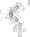
- FIG Fig. 2 An embodiment of an inverse microscope 1 designed for light-sheet microscopy with correction elements 12 in the form of Alvarez plates and a meniscus lens 10 is shown in FIG Fig. 2 shown.
- the angles ⁇ 1 and ⁇ 2 are each 45 °.
- the correction elements 12 serve to correct aberrations that may occur due to the oblique passage of the illumination radiation BS through the bottom of the sample holder 7.
- the optional meniscus lens 10 assists in the passage of the illumination radiation BS from air into an immersion medium 18 and into the liquid 8 as well as for a detection radiation DS from the liquid 8 into the immersion medium 18 and into the air.
- the sample holder 7 is held on the sample table 11.
- the sample table 11 itself is controlled in an XY plane spanned by the X-axis X and the Y-axis Y XY plane controlled by means not shown drives.
- the illumination objective 2 and the detection objective 3 are each controlled by means of a lens drive 14, which is designed here as a piezo drive, along the first optical axis A1 or along the second optical axis A2 controlled.
- the illumination radiation BS is provided by a laser module 15 and shaped by means of a beam shaping unit 16.
- the beam shaping 16 is, for example, an optical system by means of which the illumination radiation BS provided is, for example, collimated.
- a scanner 17 Downstream of the beam-shaping unit 16 there is a scanner 17 by means of which the shaped illumination radiation BS can be deflected in two directions in a controlled manner (X-Y scanner).
- the illumination objective 2 is arranged on the first optical axis A1.
- the illumination radiation BS deflected by the scanner 17 reaches the illumination objective 2 and is shaped and / or focused by the latter.
- the detection radiation DS is directed along the second optical axis A2 onto a detector 9 and can be detected by it.
- a control unit 13 is provided which is in a suitable connection for data transmission with the elements to be controlled.
- control unit 13 is additionally configured for the acquisition, storage and / or evaluation of measured values.
- control unit 13 further elements and units of the microscope 1 can be controllable and / or measured values can be obtained from these and evaluated.
- the first coordinate system is the coordinate system of the entire assembly with an X-axis X, a Y-axis Y and a Z-axis Z.
- the sample holder 7, in particular its bottom is parallel to one through the X-axis X and the Y -Axis aligned Y spanned XY-plane.
- the second coordinate system is the coordinate system of the detector 9 with the X-axis X, a y-axis y 'and a z-axis z'.
- the X-axis X is identical in both coordinate systems and directed orthogonal to the drawing plane of the figures.
- the two other axes Y and Y 'or Z and Z', can be converted by a rotation about the X-axis X into each other.
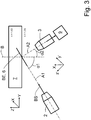
- the following exemplary embodiments are based, for example, on an inverted light-sheet microscope in which the first optical axis A1 of the illumination objective 2 forms an angle ⁇ 1 of 60 ° to the reference axis B and the second optical axis A2 of the detection objective 3 encloses an angle ⁇ 2 of 30 ° ( Fig. 3 ).
- An optional meniscus lens 10 is not shown in all figures for clarity.
- a light sheet 6 is generated or generated in the image plane BE.
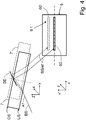
- the detector surface 9.1 is in the Fig. 4 shown in a plan view, while the sample holder 7 and the light sheet 6 are shown in a side view. From these mutually rotated views results in the illustrated orientation of the coordinate system of the detector 9 with the axes X, y 'and z'.
- the sample holder 7 is displaced in the direction of the Z-axis Z, until the portion of the illumination radiation BSref reflected by the first side surface OS, in the illustrated embodiment from the top, is detected.
- the image plane BE is fixed.
- a relative position of the sample holder 7 and of the detector 9 relative to one another is changed such that an actual position of the portion of the illumination radiation BSref detected as image 60 approximates a desired position of the image 60 on the detector surface 9.1 of the detector 9 (FIG. Fig. 4 ).
- the actual position of the sample holder 7 in the direction of the Z-axis Z is optimally adjusted when the image 60 of the cross section of the light sheet 6 is located centrally on the detector surface 9.1.
- the reflection BSref at the first side surface OS can be positioned centrally on the detector surface 9.1.
- the reflection BSref caused by the second side surface US can only be adjusted centrally in the case of a further displacement in the positive direction along the Z-axis Z.
- the image 60 is imaged centrally in a desired position on the detector surface 9, as shown in FIG Fig. 4 is shown schematically.
- the described adjustment of the sample holder 7 can be supplemented by a determination of the thickness d, for example, of the bottom of the sample holder 7.
- a determination of the thickness d for example, of the bottom of the sample holder 7.
- FIG Fig. 5 An exemplary beam path of the illumination radiation BS and the detection radiation DS or of a reflected component BSref of the illumination radiation BS is shown in FIG Fig. 5 shown.
- the illumination radiation BS is directed along the first optical axis A1 at an angle of 60 ° to the perpendicular on the underside US of the sample holder 7.
- the illumination radiation BS is refracted towards the solder and runs until to the top OS of the sample holder 7 at an angle of 48 °.
- the reflection of the portion of the illumination radiation BSref back to the second side surface US takes place in an image plane BE.
- the latter is again refracted away from the solder and passes along the second optical axis A2 as detection radiation DS, for example to the detector 9 (not shown, cf. Fig. 4 ).
- Aberrations that occur during an oblique passage of the illumination radiation BS through the sample holder 7 are substantially dependent on the thickness d, ie the distance from the first and second side surface OS, US.
- the correction elements 12 Fig. 2 slidably mounted in the illumination lens 2 and / or the detection lens 3, to tune by a shift of the correction elements 12 to each other an aberration correction to the thickness d.
- the thickness d of the sample holder 7 can be determined from the first and second side surfaces OS, US based on the reflections BSref.
- the two reflections BSref are shown schematically, where d is the thickness and d 'is a displacement distance of the sample holder 7 in the positive direction along the Z-axis Z.
- the determination of the thickness d is carried out as follows: First, the sample holder 7 is adjusted so that the reflection BSref from the first side surface OS in the desired position, for example in the center, as an image 60 on the detector surface 9.1 is (see Fig. 4 ) and the sample holder 7 has no inclination.
- the angle between illuminating radiation BS and reference axis B in the example outside the sample holder is 60 °, but within the sample holder 7 due to the refraction occurring 48 °.
- the reference axis B passes through the image plane BE (see Fig. 3 ) and by the impact point of the illumination radiation BS shown on the first side surface OS.
- ⁇ y denotes a distance between the passage point of the illumination radiation BS through the second side surface US and an impact point on the first side surface US.
- the sample holder 7 is displaced in the positive direction along the Z-axis Z until the reflection BSref of the second side surface US in the desired position as image 60 on the detector surface is 9.1 (see Fig. 4 ).
- the required displacement distance d ' is determined, for example, measured or calculated.
- the angle between the unbroken illumination radiation BS and the reference axis B is now 60 ° in the example.
- the thickness d is calculated from d '* tan (60 °) / tan (48 °).
- an inclination correction may additionally be performed by generating a light sheet 6 having a wavelength which is not used for imaging, e.g. B. in the range of infrared light.
- This light sheet 6 can be used permanently or at certain times, for example, during an experiment to control the actual position of the sample holder 7, in particular its actual position in the direction of the Z-axis Z, and optionally to correct during the experiment.
- a beam for example a Gauss beam, a Bessel beam or a Mathieustrahl can be used.
- the detector 9 a four-quadrant diode can be used.
- an autocollimation telescope can be directed onto the sample holder 7.
- a misalignment of the sample holder 7 is converted into a shift of the reflex BSref on the detector 9 of the autocollimation telescope. With this approach, only the tilt angle can be adjusted.
- Another possible embodiment requires a collimated laser, which is directed to the sample holder 7.
- the laser is aligned parallel to the solder, for example to the reference axis B.
- the reflection BSref is reflected, for example, by means of a beam splitter or a pole optic and registered on a four-quadrant diode. With the help of the signal of the four-quadrant diode, the inclination of the sample holder 7 can now be adjusted and corrected. An adjustment of the actual position in the direction of the Z-axis Z is not possible with this embodiment.
- the two aforementioned methods are suitable for conventional microscope systems and light-beam microscopes.
- the inclination and / or the focus position of the detection objective 3 can be iteratively adjusted in order to approximate or, for example, maximize measured values of the selected image quality measure to desired measured values.
- the sample 5 to be measured itself can be used or the beam profile of a beam of the selected illumination radiation BS is analyzed.
- the topography of the sample 5 is determined by measuring the sharpness or another image quality criterion of the resting sample 5 at at least three points and by a corresponding readjustment of the distances of at least one of the objectives 2, 3 to the sample 5 and from this the local cover glass tilt calculated.
- nanoparticles resting on the sample holder 7 or markings applied to the sample holder 7 can act as samples 5.
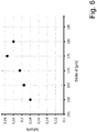
- Fig. 6 is an example of a relationship between the thickness d and the Schmgütemposiness of a sample holder 7 a priori unknown thickness d shown.
- the correction elements 12 or at least the correction element 12 present in the beam path of the detection radiation DS is adjusted stepwise to a possible thickness d of the sample holder 7. As a step size 5 microns are selected starting with a thickness d of 160 microns. With each selected setting of the correction elements 12 and the correction element 12, a sharpness of an image detected by means of the detection radiation DS is determined.
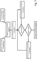
- Fig. 7 is a flowchart of a sequence of an embodiment of the inventive method for determining the thickness d and an adjustment of the at least one correction element 12 as a function of the thickness d shown.
- An initial value of the image quality measure (image quality metric) can optionally be entered by a user or specified, for example, on the basis of a thickness determination using the reflected component BSref.
- the thus determined or predetermined thickness d serves as a starting value and first Adjustment of the at least one correction element 12. Subsequently, the correction element 12 is brought into a setting which corresponds to a greater thickness d. If the value of the image quality measure determined with this setting increases, a setting is selected which in turn corresponds to a larger thickness d. This loop can be repeated until the value of the image quality measure no longer rises or falls again.
- the value of the quality of image value decreases after selection of a setting of the at least one correction element 12, a setting is selected which is associated with a reduced thickness d compared to the previous setting. If a setting is found in which a value of the image quality measure is maximum, the at least one correction element 12 is set and the control loop can be terminated. It is advantageous if a termination criterion is specified, at the fulfillment of which the control loop is terminated. Thus, for example, a minimum difference of the values of the image quality measure can be defined, below which an abort occurs.
Abstract
Die Erfindung betrifft ein Verfahren zur Bestimmung der Dicke (d) einer für eine Beleuchtungsstrahlung (BS) transparenten und zur Aufnahme einer Probe (5) ausgebildeten Probenhalterung (7) im Strahlengang eines Mikroskops (1). Die Probenhalterung (7), die eine erste Seitenfläche (OS) und eine zweite Seitenfläche (US) aufweist, wird in einer Probenebene (4) angeordnet und erste Seitenfläche (OS) und zweite Seitenfläche (US) der Probenhalterung (7) werden parallel zur Probenebene (4) ausgerichtet. Es wird mindestens eine Bündel der Beleuchtungsstrahlung (BS) entlang einer ersten optischen Achse (A1) unter einem Beleuchtungswinkel auf die ausgerichtete Probenhalterung (7) gerichtet und mindestens zwei Messwerte eines reflektierten Anteils (BSref) der Beleuchtungsstrahlung (BS) oder mindestens zwei Messwerte einer durch die Beleuchtungsstrahlung (BS) bewirkten Detektionsstrahlung (DS) erfasst.The invention relates to a method for determining the thickness (d) of a sample holder (7) transparent to illumination radiation (BS) and designed to receive a sample (5) in the beam path of a microscope (1). The sample holder (7) having a first side surface (OS) and a second side surface (US) is disposed in a sample plane (4) and first side surface (OS) and second side surface (US) of the sample holder (7) become parallel to Aligned sample plane (4). At least one bundle of the illumination radiation (BS) is directed along a first optical axis (A1) at an aligned angle to the aligned sample holder (7) and at least two measured values of a reflected portion (BSref) of the illumination radiation (BS) or at least two measured values of one the illumination radiation (BS) detected detection radiation (DS) detected.
In Abhängigkeit der mindestens zwei erfassten Messwerte wird ein Abstand von erster und zweiter Seitenfläche (OS, US) in Richtung der Z-Achse (Z) zueinander als Dicke (d) ermittelt.Depending on the at least two recorded measured values, a distance from the first and second side surfaces (OS, US) in the direction of the Z-axis (Z) relative to each other is determined as the thickness (d).
Die Erfindung betrifft ferner ein Verfahren zur Erfassung von Bilddaten.

Description
Die Erfindung betrifft ein Verfahren zur Bestimmung der Dicke einer Probenhalterung im Strahlengang eines Mikroskops.The invention relates to a method for determining the thickness of a sample holder in the beam path of a microscope.
Eine der Hauptanwendungen der Lichtblattmikroskopie liegt in der Bildgebung mittelgroßer Proben, beispielsweise von Organismen, mit einer Größe von einigen 100 µm bis hin zu wenigen Millimetern. In der Regel werden diese Proben in Agarose eingebettet und in einer Glaskapillare angeordnet. Zur Untersuchung der Probe wird die Glaskapillare in eine wassergefüllte Probenkammer eingebracht und die Agarose mit der Probe wird ein Stück weit aus der Kapillare herausgedrückt. Die Probe wird mit einem Lichtblatt beleuchtet. Die in der Probe angeregte und von dieser ausgehende Fluoreszenz wird mit einem Detektionsobjektiv, das senkrecht zum Lichtblatt und damit auch senkrecht zur Lichtblattoptik steht, auf einen Detektor, insbesondere eine Kamera, abgebildet.One of the main applications of light sheet microscopy is in the imaging of medium sized samples, for example of organisms, ranging in size from a few hundred microns down to a few millimeters. As a rule, these samples are embedded in agarose and placed in a glass capillary. To examine the sample, the glass capillary is placed in a water-filled sample chamber and the agarose with the sample is pushed out a little way out of the capillary. The sample is illuminated with a light sheet. The fluorescence excited in the sample and originating therefrom is imaged onto a detector, in particular a camera, with a detection objective which is perpendicular to the light sheet and thus also perpendicular to the light sheet optics.
Ein Aufbau eines Mikroskops 1 für die Lichtblattmikroskopie (SPIM-Aufbau; Single Plane Illumination Microscopy) umfasst gemäß dem Stand der Technik ein Beleuchtungsobjektiv 2 mit einer ersten optischen Achse 1 und ein Detektionsobjektiv 3 mit einer zweiten optischen Achse A2 (nachfolgend auch als SPIM-Objektive bezeichnet), die jeweils unter einem Winkel von 45° zu einer Probenebene 4 und einem rechten Winkel zueinander von oben auf die Probenebene 4 gerichtet sind (siehe
Dieser Ansatz bietet den Vorteil einer hohen Auflösung in axialer Richtung, da mittels des Beleuchtungsobjektivs 2 und gegebenenfalls weiterer optisch wirksamer Elemente ein dünnes Lichtblatt 6 erzeugt werden kann. Aufgrund der höheren Auflösung können kleinere Proben 5 untersucht werden. Zusätzlich wird die störende Hintergrundfluoreszenz deutlich reduziert und damit das Signal/Hintergrund-Verhältnis verbessert.This approach offers the advantage of a high resolution in the axial direction, since a
Um eine einfachere Probenpräparation in Standard-Probenbehältern wie z. B. Multiwellplatten zu ermöglichen, kann die 45°-Konfiguration zwar beibehalten werden, aber die beiden SPIM-Objektive 2, 3 sind in einer inversen Anordnung von unten durch den transparenten Boden der Probenhalterung 7 in die Probenebene 4 gerichtet (
Weitere technische Schwierigkeiten treten auf, wenn in dem Strahlengang des Beleuchtungsobjektivs 2 und/oder des Detektionsobjektivs 3 beispielsweise sogenannte Alvarezplatten als Korrekturelemente 12 (
Eine Möglichkeit zur Korrektur von Aberrationen eines Mikroskops, die durch ein Deckglas bedingt sind, ist aus der Publikation von
Ein mögliches Verfahren zur Positionierung eines Probenhalters in einem Strahlengang eines Mikroskops ist in der dato nicht veröffentlichten
Neben der Positionierung der Probenhalterung können Aberrationen auch durch Abweichungen der tatsächlichen Dicke einer Probenhalterung von einer Nenndicke verursacht sein. Handelsübliche Deckgläser als auch die Böden von Petrischalen, Multiwell-Platten und ähnlichen Probenbehältnissen (nachfolgend zusammenfassend als Probenhalterung bezeichnet) weisen eine zulässige Streuung der Glas- beziehungsweise Materialdicke um die Nenndicke auf. So ist der Dickenbereich beispielsweise bei Deckgläsern der Stärke 1.5 mit 160-190 µm angegeben, die der Stärke 1 mit 130-160 µm. Wenn also beispielsweise das Korrekturelement für eine Nenndicke von 175 µm konzipiert oder eingestellt wurde, führt ein Deckglas oder ein Boden, beispielsweise ein Glasboden, mit einer Dicke von 160 µm bei dem für die inverse Konfiguration erforderlichen schiefen Durchgang beispielsweise einer Beleuchtungsstrahlung durch die Probenhalterung zu beträchtlichen Aberrationen, insbesondere bei hohen numerischen Aperturen.In addition to positioning the sample holder, aberrations may also be caused by deviations in the actual thickness of a sample holder from a nominal thickness. Commercially available coverslips as well as the bottoms of petri dishes, multiwell plates and similar sample containers (collectively referred to below as sample holder) have a permissible scattering of the glass or material thickness around the nominal thickness. For example, the thickness range is given for cover glasses of thickness 1.5 with 160-190 microns, the thickness of 1 with 130-160 microns. Thus, for example, if the correction element was designed or adjusted for a nominal thickness of 175 μm, a cover glass or a bottom, for example a glass bottom, with a thickness of 160 μm leads to considerable oblique passage through the sample holder, for example, for the inverse configuration Aberrations, especially at high numerical apertures.
Problematisch ist dabei, dass die Dicke des Deckglases oder des Bodens der Probenhalterung a priori nicht bekannt ist, und daher technische Lösungen benötigt werden, um die aktuelle Dicke und gegebenenfalls die erforderlichen Korrekturparameter des adaptiven Korrekturelements zu ermitteln und einzustellen.The problem is that the thickness of the cover glass or the bottom of the sample holder is not known a priori, and therefore technical solutions are needed to determine the current thickness and, where appropriate, the required correction parameters of the adaptive correction element and set.
Der Erfindung liegt die Aufgabe zugrunde, ein Verfahren zur Bestimmung der Dicke einer Probenhalterung im Strahlengang eines Mikroskops vorzuschlagen.The invention has the object to provide a method for determining the thickness of a sample holder in the beam path of a microscope.
Die Aufgabe wird durch den Gegenstand des unabhängigen Anspruchs 1 gelöst. Vorteilhafte Ausgestaltungen sind in den abhängigen und nebengeordneten Ansprüchen angegeben.The object is solved by the subject matter of
Das Verfahren zur Bestimmung der Dicke einer für eine Beleuchtungsstrahlung transparenten und zur Aufnahme einer Probe ausgebildeten Probenhalterung im Strahlengang eines Mikroskops, umfasst die folgenden Schritte.
Ein Schritt A betrifft das Anordnen der Probenhalterung, die eine erste Grenzfläche und eine zweite Grenzfläche aufweist, in einer Probenebene. Die Probenebene befindet sich in einer durch eine X-Achse und eine Y-Achse eines kartesischen Koordinatensystems aufgespannten XY-Ebene.
In Schritt B erfolgt ein Ausrichten oder Justieren der ersten Grenzfläche und der zweiten Grenzfläche parallel zur Probenebene.
In einem Schritt C wird mindestens ein Bündel der Beleuchtungsstrahlung entlang einer ersten optischen Achse (Beleuchtungsachse) unter einem Beleuchtungswinkel auf die justierte Probenhalterung gerichtet.The method for determining the thickness of a sample holder transparent to illumination radiation and designed to receive a sample in the beam path of a microscope comprises the following steps.
A step A relates to arranging the sample holder having a first interface and a second interface in a sample plane. The sample plane is located in an XY plane spanned by an X axis and a Y axis of a Cartesian coordinate system.
In step B, alignment or adjustment of the first interface and the second interface is parallel to the sample plane.
In a step C, at least one bundle of the illumination radiation is directed along a first optical axis (illumination axis) at an illumination angle onto the adjusted sample holder.
Ein Schritt D betrifft das Erfassen mindestens zweier Messwerte eines reflektierten Anteils der Beleuchtungsstrahlung oder mindestens zweier Messwerte einer durch die Beleuchtungsstrahlung bewirkten Detektionsstrahlung.
Abschließend erfolgt in Schritt E in Abhängigkeit der mindestens zwei erfassten Messwerte ein Ermitteln eines Abstands von erster und zweiter Seitenfläche in Richtung der Z-Achse zueinander als Dicke.A step D relates to detecting at least two measured values of a reflected portion of the illumination radiation or of at least two measured values of a detection radiation caused by the illumination radiation.
Finally, in step E, a determination of a distance from the first and second side surfaces in the direction of the Z axis relative to one another as a thickness takes place as a function of the at least two measured values recorded.
Die Begriffe der Probenhalterung, Boden der Probenhalterung und Deckglas werden in dieser Beschreibung synonym verwendet, falls nicht ausdrücklich eine andere Bedeutung angegeben ist.The terms sample holder, bottom of sample holder and cover glass are used interchangeably throughout this specification unless expressly stated otherwise.
Unter einer Detektionsstrahlung sind an der Probe reflektierte Beleuchtungsstrahlung und/oder durch die Beleuchtungsstrahlung in der Probe bewirkte Strahlung, insbesondere angeregte Fluoreszenzstrahlung, zu verstehen. Die ersten und zweiten Grenzflächen sind beispielsweise Seitenflächen der Probenhalterung und werden nachfolgend auch als erste Seitenfläche und zweite Seitenfläche bezeichnet.Detection radiation is to be understood as illumination radiation reflected at the specimen and / or radiation caused by the illumination radiation in the specimen, in particular excited fluorescence radiation. The first and second interfaces are, for example, side surfaces of the sample holder and are also referred to below as first side surface and second side surface.
In dem erfindungsgemäßen Verfahren werden Messsignale verwendet, deren Werte maßgeblich von der Dicke der Probenhalterung beeinflusst werden. Die ermittelte Information der Dicke der Probenhalterung kann vorteilhaft dazu verwendet werden, um erforderliche Korrekturen im Strahlengang vorzunehmen und beispielsweise Aberrationen zu reduzieren. So kann im Strahlengang der Beleuchtungsstrahlung, in einem Strahlengang des reflektierten Anteils und/oder in einem Strahlengang der Detektionsstrahlung angeordnete optisch wirkende Korrekturelemente in Abhängigkeit der ermittelten Dicke angesteuert und deren relative Positionen und optischen Korrekturwirkungen in dem jeweiligen Strahlengang eingestellt werden.In the method according to the invention, measuring signals are used whose values are significantly influenced by the thickness of the sample holder. The determined information of the thickness of the sample holder can advantageously be used to make necessary corrections in the beam path and, for example, to reduce aberrations. Thus, in the beam path of the illumination radiation, optically acting correction elements arranged in a beam path of the reflected portion and / or in a beam path of the detection radiation can be controlled as a function of the determined thickness and their relative positions and optical correction effects can be set in the respective beam path.
Korrekturelemente sind beispielsweise Alvarezplatten, die gegeneinander gesteuert verschiebbar sind (auch als Alvarez-Manipulator bezeichnet), sodass als optische Wirkung korrekt zueinander eingestellter Alvarezplatten Aberrationen einer spezifischen Konstellation von Objektiven, Wellenlängen der Beleuchtungsstrahlung, Detektionsstrahlung und/oder Probenhalterung reduziert oder gar kompensiert werden. Als Korrekturelemente können zusätzlich oder alternativ gesteuert verformbare Spiegel (deformable mirror), ansteuerbare Spiegel- oder Mikrospiegelarrays (digital mirror device) und/oder Lichtmodulatoren (spatial light modulator, SLM) verwendet werden.Correction elements are, for example, Alvarez plates, which are mutually displaceable controlled (also referred to as Alvarez manipulator), so that aberrations of a specific constellation of lenses, wavelengths of the illumination radiation, detection radiation and / or sample holder are reduced or even compensated as an optical effect correctly set Alvarezplatten. Additionally or alternatively, deformable mirrors, controllable mirror or micromirror arrays (digital mirror device) and / or spatial light modulators (SLM) may be used as correction elements.
Eine optische Anordnung, insbesondere eine inverse Lichtblattanordnung, die zur Ausführung des erfindungsgemäßen Verfahrens in einer seiner Ausgestaltungen verwendet wird, weist beispielsweise optional ein Korrekturelement in dem Strahlengang der Beleuchtungsstrahlung auf. Dieses Korrekturelement, welches auch aus mehreren Teilelementen, beispielsweise aus zwei Alvarezplatten, bestehen kann, kann für eine statische Korrektur von Aberrationen ausgelegt sein. In dem Strahlengang der Detektionsstrahlung ist ein Korrekturelement hinsichtlich seiner optischen Wirkungen gesteuert veränderbar ausgestaltet, sodass mittels einer entsprechenden Ansteuerung des Korrekturelements auftretende Aberrationen beeinflusst, insbesondere reduziert werden können. Die Korrekturelemente in den verschiedenen Strahlengängen können gleichartig oder gar identisch sein. Es können auch in den Strahlengängen von Beleuchtungsstrahlung und Detektionsstrahlung Korrekturelemente vorhanden sein, die ansteuerbar sind und deren gemeinsame optische Wirkung zu einer Reduzierung von Aberrationen führt.An optical arrangement, in particular an inverse light sheet arrangement, which is used for carrying out the method according to the invention in one of its embodiments, for example, optionally has a correction element in the beam path of the illumination radiation. This correction element, which may also consist of several sub-elements, for example of two Alvarez plates, may be designed for a static correction of aberrations. In the beam path of the detection radiation, a correction element is designed to be changeable under the control of its optical effects, so that aberrations occurring by means of a corresponding activation of the correction element can be influenced, in particular reduced. The correction elements in the different beam paths may be identical or even identical. It can also be present in the beam paths of illumination radiation and detection radiation correction elements which are controllable and their combined optical effect leads to a reduction of aberrations.
In weiteren Ausgestaltungen des Verfahrens wird die Beleuchtungsstrahlung in Form eines Lichtblatts auf die Probenhalterung gerichtet und ein Lichtblatt in der Probenebene erzeugt. Ist in der Probenebene eine zu untersuchende Probe vorhanden, wird diese mit dem Lichtblatt beleuchtet und es können entsprechend Bilder der beleuchteten Bereiche der Probe erfasst werden.In further embodiments of the method, the illumination radiation is directed in the form of a light sheet on the sample holder and generates a light sheet in the sample plane. If a sample to be examined is present in the sample plane, it is illuminated with the light sheet and correspondingly images of the illuminated regions of the sample can be detected.
Es ist also möglich, dass verschiedene Beleuchtungsstrahlungen eingesetzt werden, um beispielsweise unterschiedliche Teilschritte des erfindungsgemäßen Verfahrens auszuführen. Ein Lichtblatt kann als ein statisches oder dynamisches Lichtblatt erzeugt werden, wie dies dem Fachmann aus dem Stand der Technik bekannt ist.It is therefore possible that different illumination radiations are used, for example, to carry out different partial steps of the method according to the invention. A light sheet may be generated as a static or dynamic light sheet, as known to those skilled in the art.
Die Beleuchtungsstrahlung wird als mindestens ein Bündel von Einzelstrahlen (Strahlenbündel), bereitgestellt und auf die Probenhalterung gerichtet. Eine typische Form der Beleuchtungsstrahlung ist ein sogenannter Gauss-Strahl.The illumination radiation is provided as at least one bundle of individual beams (bundles of rays) and directed to the sample holder. A typical form of illumination radiation is a so-called Gaussian beam.
In weiteren Ausgestaltungen des erfindungsgemäßen Verfahrens kann eine Strahlung mit selbstrekonstruierenden Strahlen oder diffraktionsfreien Strahlen (englisch: non-diffractive beams) als Beleuchtungsstrahlung verwendet sein und beispielsweise in Form eines Besselstrahls, eines Mathieustrahls, eines Sinc3-Strahls, eines Lattice-Lightsheets, eines Coherent Besselstrahls, eines Sectioned Besselstrahl oder eines Airystrahls ausgebildet und auf die Probenhalterung gerichtet werden.In further embodiments of the method according to the invention, radiation with self-reconstructing beams or non-diffractive beams can be used as illumination radiation and, for example, in the form of a Bessel beam, a Mathie beam, a Sinc 3 beam, a Lattice light sheet, a Coherent Bessel beam, a sectioned Bessel beam or an air jet and trained on the sample holder.
Ein Mathieustrahl kann als ein ausbreitungsinvariantes optisches Feld (propagation-invariant optical field) gemäß der Helmholtzgleichung mit elliptischen Koordinaten angesehen werden (
Von einem Gauss-Strahl abweichende Strahlformen z.B. der Sinc3-Strahl, weisen eine intrinsische Strukturierung auf, die sich besonders für die Analyse der Bildgütemaße Schärfe und/oder Kontrast eignet, wie dies weiter unten beschrieben ist.Beam shapes deviating from a Gaussian beam, for example the Sinc 3 beam, have an intrinsic structuring which is particularly suitable for the analysis of the image quality measures sharpness and / or contrast, as described below.
Besonders in Bereichen der Probe, die eine weitgehend homogene Fluoreszenzemission zeigen, kann ein durch Wirkung der strukturierten Strahlformen strukturiertes Lichtblatt selbst als ein Testgitter verwendet werden. Anhand eines solchen Gitters kann z. B. der Kontrast maximiert werden. Dazu wird die Probe mit dem strukturierten Lichtblatt beleuchtet, wobei die auf die Probe gebrachten unterschiedlichen Intensitäten der strukturierten Beleuchtungsstrahlung entsprechend zu einer strukturierten Fluoreszenzanregung in der Probe führt beziehungsweise führen kann. Mittels eines geeigneten Detektors werden Signale der strukturiert angeregten Fluoreszenzstrahlung als Detektionsstrahlung erfasst und maximale Signalintensitäten als Imax und minimale Signalintensitäten als Imin ermittelt und gespeichert. Eine Modulationstiefe der Gitterstruktur kann mit der Beziehung Imax-Imin/Imax+Imin analysiert werden. Es ist aber ebenso möglich, die unten beschriebenen Bildgütekriterien auf diese Teststruktur anzuwenden.Especially in regions of the sample which exhibit a largely homogeneous fluorescence emission, a light sheet structured by the action of the structured beam shapes can itself be used as a test grid. On the basis of such a grid can z. B. the contrast can be maximized. For this purpose, the sample is illuminated with the structured light sheet, with the different intensities of the structured illumination radiation placed on the sample correspondingly leading to or leading to a structured fluorescence excitation in the sample. By means of a suitable detector, signals of the structurally excited fluorescence radiation are detected as detection radiation, and maximum signal intensities are determined and stored as I max and minimum signal intensities as I min . A modulation depth of the lattice structure can be analyzed with the relationship I max -I min / I max + I min . However, it is also possible to apply the image quality criteria described below to this test structure.
Die Dicke der Probenhalterung wird indirekt auf der Grundlage mindestens zweier Messwerte ermittelt. Eine Möglichkeit besteht in der Auswertung von reflektierten Anteilen der Beleuchtungsstrahlung (Reflexe).The thickness of the sample holder is determined indirectly on the basis of at least two measured values. One possibility is the evaluation of reflected portions of the illumination radiation (reflections).
An den Grenzflächen, beispielsweise den Ober- beziehungsweise Unterseiten von Probenhalterungen, kommt es meist zu Reflexionen von Anteilen der Beleuchtungsstrahlung. Reflexionen an diesen Grenzflächen erfolgen mit einem Reflexionsgrad abhängig von der Differenz des Brechungsindex zwischen den Medien (Glas-Immersion, Glas-Probe) und vom Einfallswinkel, beispielsweise von jeweils etwa 3%. Der reflektierte Anteil der Beleuchtungsstrahlung liegt dabei zumeist nahezu vollständig innerhalb der Detektions-NA (Numerische Apertur des Detektionsobjektivs). Dies hat zur Folge, dass der reflektierte Anteil weitgehend auf einem mit dem Detektionsobjektiv optisch verbundenen Detektor abgebildet werden kann. Dieser reflektierte Anteil kann nun genutzt werden, um die Dicke der Probenhalterung, beispielsweise deren für die Beleuchtungsstrahlung und den reflektierten Anteil transparenten Boden, zu ermitteln. Um diesen reflektierten Anteil zu detektieren, kann ein gegebenenfalls im Strahlengang befindlicher Emissionsfilter für die Fluoreszenzmikroskopie entfernt werden.At the interfaces, for example the upper or lower sides of sample holders, reflections of portions of the illumination radiation usually occur. Reflections at these interfaces occur with a reflectance depending on the difference in refractive index between the media (glass immersion, glass sample) and the angle of incidence, for example, about 3% each. The reflected portion of the illumination radiation is usually almost completely within the detection NA (numerical aperture of the detection objective). This has the consequence that the reflected portion can be largely imaged on a detector optically connected to the detection lens. This reflected portion can now be used to determine the thickness of the sample holder, for example its bottom transparent to the illumination radiation and the reflected portion. To detect this reflected portion, a optionally located in the beam path emission filter for fluorescence microscopy are removed.
Dazu kann in einer vorteilhaften Ausgestaltung des erfindungsgemäßen Verfahrens in Schritt C mindestens ein Bündel der Beleuchtungsstrahlung entlang einer ersten optischen Achse (Beleuchtungsachse) unter einem Beleuchtungswinkel auf die ausgerichtete Probenhalterung gelenkt werden, wobei der Beleuchtungswinkel zwischen der ersten optischen Achse und einer senkrecht auf der XY-Ebene stehenden Bezugsachse ungleich Null ist. Die Beleuchtungsstrahlung ist also schräg, beispielsweise unter einem Beleuchtungswinkel von 45° oder 60° auf die Probenhalterung gerichtet. In Schritt D wird ein reflektierter Anteil der Beleuchtungsstrahlung, der von der ersten Seitenfläche oder von der zweiten Seitenfläche der Probenhalterung in einer Soll-Lage mittels eines Detektors als ein erster Messwert erfasst. Anschließend wird die Probenhalterung in Richtung einer senkrecht auf der XY-Ebene gerichteten Z-Achse verschoben, bis ein reflektierter Anteil der jeweils anderen Seitenfläche in der Soll-Lage mittels des Detektors als zweiter Messwert erfasst wird. Die Verschiebestrecke in Richtung der Z-Achse ist als eine Veränderung der Relativlage von Probenhalterung und beispielsweise einem Beleuchtungsobjektiv und/oder einem Detektionsobjektiv zu verstehen. Die Verschiebestrecke kann somit auch durch eine Bewegung von Beleuchtungsobjektiv, Detektionsobjektiv und/oder Detektor sowie durch eine kombinierte Bewegung von Probenhalterung, Beleuchtungsobjektiv, Detektionsobjektiv und/oder Detektor realisiert werden.For this purpose, in an advantageous embodiment of the method according to the invention in step C, at least one bundle of illumination radiation along a first optical axis (illumination axis) can be directed onto the aligned sample holder at an illumination angle, the illumination angle being between the first optical axis and one perpendicular to the XY axis. Level reference axis is not equal to zero. The illumination radiation is thus obliquely directed, for example, at an illumination angle of 45 ° or 60 ° to the sample holder. In step D, a reflected portion of the illumination radiation detected from the first side surface or from the second side surface of the sample holder in a desired position by means of a detector is detected as a first measured value. Subsequently, the sample holder is displaced in the direction of a Z axis directed perpendicular to the XY plane, until a reflected portion of the respective other side surface in the desired position is detected by means of the detector as a second measured value. The displacement distance in the direction of the Z-axis is to be understood as a change in the relative position of the sample holder and, for example, an illumination objective and / or a detection objective. The displacement path can thus also be realized by a movement of the illumination objective, detection objective and / or detector and by a combined movement of the sample holder, illumination objective, detection objective and / or detector.
Eine Soll-Lage ist erreicht, wenn die Probenhalterung eine erwartete oder gewünschte Positionierung einnimmt. Es kann eine zulässige Toleranz der Soll-Lage festgelegt werden.A desired position is reached when the sample holder assumes an expected or desired positioning. An allowable tolerance of the desired position can be specified.
In Schritt E wird anhand des ersten und zweiten Messwerts eine Verschiebestrecke in Richtung der Z-Achse ermittelt, die erforderlich war, um die reflektierten Anteile der ersten und zweiten Seitenflächen in der Soll-Lage zu erfassen. Anhand der ersten und zweiten Messwerte wird die Dicke ermittelt. Wenn das Material der Probenhalterung einen anderen Brechungsindex als ein zwischen dem beispielsweise Beleuchtungsobjektiv und der Probenhalterung befindliches Medium besitzt, entspricht die Verschiebestrecke nicht der Dicke der Probenhalterung.In step E, a displacement distance in the direction of the Z-axis, which was required to detect the reflected portions of the first and second side surfaces in the desired position, is determined on the basis of the first and second measured values. Based on the first and second measured values, the thickness is determined. If the material of the sample holder has a different refractive index than a medium located between, for example, the illumination objective and the sample holder, the displacement distance does not correspond to the thickness of the sample holder.
Um bei Kenntnis der Verschiebestrecke die Dicke der Probenhalterung zu ermitteln, können der Beleuchtungswinkel und ein Winkel der durch das Material der Probenhalterung gebrochenen Beleuchtungsstrahlung erfasst werden. Unter Anwendung von Winkelfunktionen (Trigonometrie) und Berücksichtigung der Verschiebestrecke kann die Dicke der Probenhalterung berechnet werden.In order to determine the thickness of the sample holder with knowledge of the displacement distance, the illumination angle and an angle of the illumination radiation refracted by the material of the sample holder can be detected. By using trigonometry and considering the displacement distance, the thickness of the sample holder can be calculated.
In einer weiteren Ausgestaltung des Verfahrens wird ein Bildgütemaß definiert, welches als ein Kriterium zur Einstellung wenigstens eines der Korrekturelemente verwendet wird. Eine aktuelle Ist-Positionierung wenigstens eines der Korrekturelemente wird dabei schrittweise oder kontinuierlich verändert. Jeder der gewählten Ist-Positionierungen wenigstens eines der Korrekturelemente werden Messwerte des Bildgütemaßes zugeordnet und abgespeichert, die an den betreffenden Ist-Positionierungen erfasst werden. Anhand der Messwerte des Bildgütemaßes wird jeweils ein aktueller Wert des Bildgütemaßes ermittelt. Liegen diese aktuellen Werte des Bildgütemaßes für eine Auswertung vor, wird eine Ist-Positionierung des wenigstens einen Korrekturelements ausgewählt, an der ein gewünschtes Bildgütemaß, also ein gewünschter Wert des Bildgütemaßes, erzielt ist. Die ausgewählte Ist-Positionierung kann als zukünftige Soll-Positionierung festgelegt werden.In a further embodiment of the method, an image quality measure is defined, which is used as a criterion for setting at least one of the correction elements. A current actual positioning of at least one of the correction elements is thereby changed stepwise or continuously. Each of the selected actual positioning of at least one of the correction elements is assigned and stored measured values of the image quality measure, which are detected at the relevant actual positioning. On the basis of the measured values of the image quality measure, a current value of the image quality measure is determined in each case. If these current values of the image quality measure are available for an evaluation, an actual positioning of the at least one correction element is selected at which a desired image quality measure, that is to say a desired value of the image quality measure, is achieved. The selected actual positioning can be defined as future target positioning.
Vorzugsweise ist vorab eine Tabelle oder eine mathematische Beziehung (Funktion) als Referenz ermittelt und wiederholt abrufbar abgespeichert worden. Diese Referenz erlaubt eine Zuordnung von Werten des Bildgütemaßes zu einer jeweiligen Dicke der Probenhalterung.Preferably, a table or a mathematical relationship (function) is determined beforehand as a reference and repeatedly retrievably stored. This reference allows assignment of values of the image quality measure to a respective thickness of the sample holder.
Zur Ausführung des Verfahrens können Messwerte wenigstens eines der Bildgütemaße Kontrast, ein Schärfemaß, Signal-Rausch-Verhältnis, Signalintensität und Parameter einer Punktbildfunktion oder Kombinationen davon verwendet werden.For carrying out the method, measured values of at least one of the image quality measures of contrast, a sharpness ratio, signal-to-noise ratio, signal intensity and parameters of a dot image function or combinations thereof can be used.
Die Dicke einer jeden Probenhalterung muss individuell auskorrigiert werden, so dass eine Verwendung einer Testprobe wie zum Beispiel eines Gitters, einer USAF-Chart o. ä. hier nicht anwendbar ist. Es ist jedoch in weiteren Ausgestaltungen des erfindungsgemäßen Verfahrens möglich, eine Probe enthaltend vereinzelte punktförmige Fluoreszenzquellen zu verwenden. Es werden mindestens zwei Messwerte des Bildgütemaßes anhand der Detektionsstrahlung wenigstens einer Anzahl der punktförmigen Fluoreszenzquellen erfasst und zur Ermittlung der Dicke der Probenhalterung verwendet. Vereinzelte punktförmige Fluoreszenzquellen überlappen sich nicht. Beispielsweise können vereinzelte fluoreszierende Nanosphären (sogenannte "beads") in die Probe eingebracht werden, um eine probenunabhängige Bildgüteanalyse nur an den sehr hellen Nanosphären vorzunehmen. Sind Nanosphären in der Probe enthalten, so kann mit dem Wissen, dass es sich näherungsweise um Punktobjekte handelt, auch die Punktbildfunktion (point spread function; PSF) der Abbildungsoptik analysiert werden um beispielsweise die FWHM (full width at half maximum) der Punktbildfunktion zu minimieren.The thickness of each specimen holder must be adjusted individually, so that the use of a test specimen such as a grid, a USAF chart or similar is not applicable here. However, it is possible in further embodiments of the method according to the invention to use a sample containing isolated punctiform fluorescence sources. At least two measured values of the image quality measure are detected on the basis of the detection radiation of at least a number of the punctiform fluorescence sources and used to determine the thickness of the sample holder. Isolated punctiform fluorescence sources do not overlap. For example, isolated fluorescent nanospheres (so-called "beads") can be introduced into the sample in order to carry out a sample-independent image quality analysis only on the very light nanospheres. If nanospheres are contained in the sample, then, knowing that they are approximately point objects, the point spread function (PSF) of the imaging optics can also be analyzed, for example to minimize the FWHM (full width at half maximum) of the dot image function ,
Als Bildgütemaß kann der Kontrast verwendet werden. Der Kontrast eines einzelnen, isolierten Objekts vor einem gleichmäßigen Hintergrund definiert sich über ![]()
![]()
Besser dafür geeignet sind Kontrast-Definitionen, die den Kontrast in jedem Bildpunkt des Bildes oder der ROI (Region of Interest) berechnen. Zusätzlich werden nur bestimmte Raumfrequenzbereiche im Fourier-Transformierten Bild betrachtet, wodurch Signal, Hintergrund und Rauschen besser isoliert werden können (
Der Kontrast in jedem Bildpunkt und je Frequenzband k ergibt sich also zu ![]()
![]()
![]()
![]()
In einer weiteren mögliche Ausgestaltung des Verfahrens wird das Schärfemaß anhand einer Analyse des Ortsfrequenzraums eines erfassten Bildes ermittelt, indem Raumfrequenzkomponenten des erfassten Bildes mittels eines Schwellwerts in beispielsweise zwei Gruppen unterteilt werden und ein Maximum beziehungsweise Minimum der in der jeweiligen Gruppe enthaltenen Raumfrequenzkomponenten als Schärfemaß verwendet wird (z. B.
Es ist ferner in einer weiteren Ausgestaltung des Verfahrens möglich, das Schärfemaß anhand einer Analyse des vierten zentralen Moments des Ortsfrequenzspektrums (Kurtosis, zentrales Moment vierter Ordnung, Wölbung) eines erfassten Bildes zu ermitteln, indem niedrige oder minimale Werte der Kurtosis ausgewählt werden (z. B. In
Um eine hohe Kompensation auftretender Aberrationen zu erreichen, werden vorteilhaft Bilder der zu vermessenden Probe zur iterativen Analyse der entsprechenden Bildgütemaße und nachfolgenden Anpassung des adaptiven Korrekturelements beziehungsweise der Korrekturelemente herangezogen.In order to achieve a high compensation of occurring aberrations, images of the sample to be measured are advantageously used for the iterative analysis of the corresponding image quality measures and subsequent adaptation of the adaptive correction element or the correction elements.
Es ist durchaus möglich, dass der iterativ zu prüfende Parameterraum zu groß ist, beziehungsweise dass das System nicht iterativ auf das globale Minimum - beispielsweise eine optimale Neigung der Probenhalterung 7 und eine optimale Fokusposition - hin optimiert werden kann, sondern in einem lokalen Minimum verharrt. Es ist daher vorteilhaft, wenn die Methode der Bildgüteauswertung in Kombination mit einer der vorgenannten Ausgestaltungen des Verfahrens ausgeführt wird. Dabei erfolgt zuerst eine Grobeinstellung der Neigung der Probenhalterung 7 und der Ist-Position in Richtung der Z-Achse Z beispielsweise mittels einer der oben beschriebenen Methoden. Im Anschluss wird eine Feineinstellung mittels einer Bildgüteauswertung durchgeführt. Diese Methode ist nicht für konventionelle Mikroskopsysteme geeignet.It is quite possible that the parameter space to be iteratively tested is too large, or that the system can not be iteratively optimized to the global minimum - for example, an optimum inclination of the
Neben der Einschränkung des möglichen und iterativ zu prüfenden Parameterraums ergibt sich ein weiterer Vorteil: wenn die Deckglasdicke durch den Lichtblattreflex bestimmt und kompensiert wird, kann das adaptive Element durch die iterative Maximierung der Bildgüte gegebenenfalls auch noch weitere, durch die Probe induzierte Aberrationen kompensieren.In addition to the limitation of the possible and iteratively tested parameter space, there is a further advantage: if the cover glass thickness is determined and compensated by the light sheet reflection, the adaptive element can optionally also compensate for further aberrations induced by the sample by iteratively maximizing the image quality.
Das erfindungsgemäße Verfahren kann Teil eines Verfahrens zur Erfassung von Bilddaten sein. Dabei können Bilddaten einer in der Probenebene des Mikroskops angeordneten Probe erhalten werden, indem mittels einer Beleuchtungsstrahlung in der Probe eine Detektionsstrahlung bewirkt und erfasst wird. Ein derartiges Verfahren umfasst die oben aufgeführten Schritte A bis E zur Bestimmung der Dicke der Probenhalterung.The method according to the invention can be part of a method for acquiring image data. In this case, image data of a sample arranged in the sample plane of the microscope can be obtained by causing and detecting detection radiation by means of illumination radiation in the sample. Such a method comprises the above-mentioned steps A to E for determining the thickness of the sample holder.
In einer vorteilhaften Ausgestaltung des Verfahrens wird ein Mikroskop benutzt, das als ein inverses Mikroskop ausgebildet ist. Das inverse Mikroskop umfasst ein Beleuchtungsobjektiv mit einer ersten optischen Achse, wobei die erste optische Achse eine durch eine X-Achse und einer zur X-Achse orthogonalen Y-Achse aufgespannten Probenebene durchstößt. Weiterhin ist ein zur Detektion von aus der Probenebene kommenden Lichts ausgebildetes Detektionsobjektiv mit einer zweiten optischen Achse vorhanden, wobei das Beleuchtungsobjektiv und das Detektionsobjektiv derart zueinander und zur Probenebene ausgerichtet sind, dass sich die erste optische Achse und die zweite optische Achse in der Probenebene schneiden und miteinander einen im Wesentlichen rechten Winkel einschließen. Die erste optische Achse und die zweite optische Achse schließen mit einer orthogonal zur Probenebene in Richtung einer Z-Achse gerichteten und als eine Bezugsachse dienenden dritten Achse jeweils einen von Null verschiedenen Winkel ein. Die vorstehend angegebene Ausgestaltung eignet sich insbesondere für die Lichtblattmikroskopie.In an advantageous embodiment of the method, a microscope is used, which is designed as an inverted microscope. The inverse microscope comprises an illumination objective having a first optical axis, wherein the first optical axis penetrates a sample plane spanned by an X-axis and a Y-axis orthogonal to the X-axis. Furthermore, a detection objective with a second optical axis is provided for detecting light coming from the sample plane, the illumination objective and the detection objective being aligned relative to each other and to the sample plane such that the first optical axis and the second optical axis intersect in the sample plane and enclose with each other a substantially right angle. The first optical axis and the second optical axis each include a non-zero angle with a third axis oriented orthogonal to the sample plane in the direction of a Z-axis and serving as a reference axis. The above-mentioned embodiment is particularly suitable for light-sheet microscopy.
Das erfindungsgemäße Verfahren wird nachfolgend beispielhaft beschrieben. Als Ist-Lage beziehungsweise als Soll-Lage werden im Folgenden die Lagen der Abbildung des reflektierten Anteils auf dem Detektor, insbesondere auf einer Detektionsfläche des Detektors, bezeichnet.The process according to the invention is described below by way of example. In the following, the positions of the image of the reflected component on the detector, in particular on a detection surface of the detector, are referred to as the actual position or as the desired position.
In den Schritten A und B wird die Probenhalterung in der Probenebene angeordnet und ausgerichtet. Das Ausrichten kann manuell oder automatisiert erfolgen. Für das Ausrichten kann bereits ein reflektierter Anteil der Beleuchtungsstrahlung und/oder einer Hilfsstrahlung, beispielsweise einer nur für den Ausrichtevorgang verwendeten Strahlung, genutzt werden und somit der Schritt C in den Vorgang des Ausrichtens der Probenhalterung mit eingebunden werden. Dazu wird beispielsweise eine Probenhalterung, die eine für die Beleuchtungsstrahlung transparenten Boden mit einer ersten Seitenfläche und einer zweiten Seitenfläche aufweist, in Richtung der Z-Achse verschoben, bis der von der ersten Seitenfläche, z. B. der Oberseite, des Bodens reflektierte Anteil der Beleuchtungsstrahlung mittels des Detektors erfasst wird. Die Relativlage der Probenhalterung und des Detektors wird vorzugsweise zueinander so eingestellt, dass eine Ist-Lage des erfassten Anteils einer Soll-Lage auf dem Detektor angenähert wird. Die Soll-Lage ist vorteilhaft mittig auf der Detektorfläche, um während der Einstellung der Soll-Lage eine Ist-Lage des reflektierten Anteils außerhalb der Detektorfläche weitgehend zu vermeiden.In steps A and B, the sample holder is placed in the sample plane and aligned. The alignment can be done manually or automatically. For the alignment, a reflected portion of the illumination radiation and / or an auxiliary radiation, for example a radiation used only for the alignment process, can already be used and thus step C can be included in the process of aligning the sample holder. For this purpose, for example, a sample holder, which has a bottom transparent to the illumination radiation with a first side surface and a second side surface, moved in the direction of the Z-axis until the first side surface, z. B. the top, the bottom reflected portion of the illumination radiation is detected by means of the detector. The relative position of the sample holder and the detector is preferably adjusted to each other so that an actual position of the detected portion of a desired position on the Detector is approximated. The desired position is advantageously centered on the detector surface in order to largely avoid an actual position of the reflected portion outside the detector surface during the setting of the desired position.
Der Boden kann beispielsweise der Boden einer Schale, beispielsweise aus Glas oder Kunststoff sein. Es ist auch möglich, dass ein Deckglas mit seiner ersten und zweiten Seitenfläche ein Boden im vorgenannten Sinn ist. Von Bedeutung ist eine hinreichende Transparenz des Materials des Bodens für die Beleuchtungsstrahlung beziehungsweise die Beleuchtungsstrahlungen, sowie die erste Seitenfläche und zweite Seitenfläche, die als Grenzflächen wirken, an denen Brechungen und/oder Reflexionen der Beleuchtungsstrahlung erfolgen können.The floor may for example be the bottom of a shell, for example made of glass or plastic. It is also possible that a cover glass with its first and second side surface is a floor in the aforementioned sense. Significant is a sufficient transparency of the material of the soil for the illumination radiation or the illumination radiations, and the first side surface and second side surface, which act as interfaces at which refractions and / or reflections of the illumination radiation can take place.
Das Vorliegen einer Verkippung der ersten Seitenfläche des Bodens um die X-Achse kann überprüft werden, indem eine Winkelabweichung der Ist-Lage von der Soll-Lage ermittelt wird. Wird dabei eine Winkelabweichung festgestellt, die größer als eine zulässige Winkelabweichung ist, wird die Probenhalterung um die X-Achse rotiert bis die Winkelabweichung minimiert ist. Optional kann eine bevorzugte Rotationsrichtung zum Ausgleich der Verkippung ermittelt werden, um zum Beispiel die Winkelabweichung auf dem kürzesten Rotationsweg auszugleichen. Anschließend wird ein Auftreten einer Abweichung der Soll-Position von der Ist-Position in Richtung der Z-Achse überprüft. Bei Auftreten einer unzulässigen Abweichung wird beziehungsweise werden die vorgenannten gegebenenfalls wiederholt. Nach Abschluss dieser Vorgänge ist die Probenhalterung parallel zur X-Achse ausgerichtet.The presence of a tilting of the first side surface of the ground about the X-axis can be checked by determining an angular deviation of the actual position from the desired position. If an angle deviation greater than an allowable angular deviation is detected, the sample holder is rotated about the X axis until the angular deviation is minimized. Optionally, a preferred direction of rotation to compensate for the tilt can be determined, for example to compensate for the angular deviation on the shortest path of rotation. Subsequently, an occurrence of a deviation of the target position from the actual position in the Z-axis direction is checked. If an impermissible deviation occurs, the above is or will be repeated if necessary. Upon completion of these operations, the sample holder is aligned parallel to the X-axis.
Optional wird in einem weiteren Ausrichtevorgang eine Ausrichtung der ersten Seitenfläche in Richtung der Y-Achse überprüft, indem die Probenhalterung in Richtung der Y-Achse verschoben wird und eine Abweichung von der Richtung der Y-Achse durch ein Auswandern des erfassten reflektierten Anteils auf dem Detektor festgestellt wird. Bei Auftreten des Auswanderns, also der Ist-Lage, des erfassten reflektierten Anteils wird die Probenhalterung um die X-Achse rotiert bis kein Auswandern mehr auftritt beziehungsweise dieses innerhalb einer zulässigen Toleranzgrenze liegt.Optionally, in a further alignment operation, alignment of the first side surface in the direction of the Y-axis is checked by moving the sample holder in the Y-axis direction and a deviation from the Y-axis direction by migrating the detected reflected portion on the detector is detected. When emigration occurs, ie the actual position, of the detected reflected portion, the sample holder is rotated about the X-axis until no more emigration occurs or this is within a permissible tolerance limit.
In dem Schritt D des Verfahrens wird die justierte Probenhalterung aus einer ersten (Soll-)Positionierung, in der ein von der ersten Seitenfläche reflektierter Anteil in einer ersten Soll-Lage erfasst wird, in Richtung der Z-Achse verschoben, bis die Abbildung des erfassten reflektierten Anteils eine zweite Soll-Lage erreicht, in der ein von der zweiten Seitenfläche, beispielsweise der Unterseite, des Bodens reflektierter Anteil erfasst wird. In Abhängigkeit von der zwischen der ersten Soll-Lage und der zweiten Soll-Lage zurückgelegten Verschiebestrecke in Richtung der Z-Achse wird ein tatsächlicher Abstand von erster und zweiter Seitenfläche in Richtung der Z-Achse zueinander ermittelt. Der so ermittelte Abstand entspricht der Dicke des Bodens.In step D of the method, the adjusted sample holder is displaced in the direction of the Z-axis from a first (desired) positioning, in which a portion reflected by the first side surface in a first desired position is detected, until the image of the detected reflected portion reaches a second target position in which a reflected from the second side surface, for example, the bottom of the soil portion is detected. Depending on the displacement distance traveled between the first desired position and the second desired position in the direction of the Z axis, an actual distance between the first and second side surfaces in the direction of the Z axis relative to each other is determined. The determined distance corresponds to the thickness of the soil.
Der Abstand beziehungsweise die Dicke des Bodens kann berechnet werden. Eine Berechnungsmöglichkeit ist unten im Zusammenhang mit den Ausführungsbeispielen angegeben.The distance or the thickness of the soil can be calculated. A calculation option is given below in connection with the exemplary embodiments.
Die Erfassung des reflektierten Anteils erfolgt mittels eines Detektors, beispielsweise mittels einer Kamera, beispielsweise umfassend einen CCD- oder CMOS-Chip oder mittels einer Vier-Quadrantendiode.The detection of the reflected portion is effected by means of a detector, for example by means of a camera, for example comprising a CCD or CMOS chip or by means of a four-quadrant diode.
Das erfindungsgemäße Verfahren ist vorteilhaft auch für Mikroskope mit einer senkrechten Ausrichtung eines Strahlengangs beziehungsweise der Strahlengänge anwendbar. Zwar fallen die Aberrationen in solch einer klassischen Anordnung auch geringer aus, für die Abbildungsqualität moderner Objektive mit großen Numerischen Aperturen sind diese Aberrationen jedoch von großer Bedeutung, insbesondere für Wasserimmersionsobjektive oder TIRF-Objektive (TIRF = total internal reflection fluorescence microscopy).The method according to the invention is advantageously also applicable to microscopes with a perpendicular orientation of a beam path or the beam paths. Although the aberrations in such a classical arrangement are also lower, these aberrations are of great importance for the imaging quality of modern objectives with large numerical apertures, in particular for water immersion objectives or TIRF objectives (TIRF = total internal reflection fluorescence microscopy).
Die Erfindung wird nachfolgend anhand von Ausführungsbeispielen und Abbildungen näher erläutert. Dabei zeigen:
- Fig. la eine schematische Darstellung eines Mikroskops mit einer 45°-Anordnung von Beleuchtungsobjektiv und Detektionsobjektiv oberhalb sowie mit einem Weitfeldobjektiv unterhalb einer Probenebene gemäß dem Stand der Technik;
-
Fig. 1b eine schematische Darstellung eines Mikroskops mit einer inversen 45°-Anordnung von Beleuchtungsobjektiv und Detektionsobjektiv unterhalb sowie mit einem Weitfeldobjektiv oberhalb einer Probenebene gemäß dem Stand der Technik; -
Fig. 2 eine schematische Darstellung eines Ausführungsbeispiels eines zur Lichtblattmikroskopie ausgebildeten Mikroskops mit Alvarezplatten und Meniskuslinse; -
Fig. 3 eine schematische Darstellung eines Ausführungsbeispiels eines inversen Lichtblattmikroskops; -
Fig. 4 eine schematische Darstellung von Soll-Lagen und Ist-Lagen reflektierter Anteile der Beleuchtungsstrahlung auf einer Detektorfläche, -
Fig. 5 eine schematische Darstellung des Prinzips der Bestimmung der Dicke der Probenhalterung, -
Fig. 6 eine schematische Darstellung des Schärfemaßes als Funktion eines unterschiedlich eingestellten Korrekturelements bei unbekannter Dicke der Probenhalterung und -
Fig. 7 ein Flussdiagramm einer Ausgestaltung des erfindungsgemäßen Verfahrens.
- 1a is a schematic representation of a microscope with a 45 ° arrangement of the illumination objective and detection objective above and with a wide field objective below a sample plane according to the prior art;
-
Fig. 1b a schematic representation of a microscope with an inverse 45 ° arrangement of the illumination lens and detection lens below and with a wide-field lens above a sample plane according to the prior art; -
Fig. 2 a schematic representation of an embodiment of a designed for light-sheet microscopy microscope with Alvarez plates and meniscus lens; -
Fig. 3 a schematic representation of an embodiment of an inverse Lichtblattmikroskops; -
Fig. 4 a schematic representation of desired positions and actual positions of reflected portions of the illumination radiation on a detector surface, -
Fig. 5 a schematic representation of the principle of determining the thickness of the sample holder, -
Fig. 6 a schematic representation of the sharpness measure as a function of a differently set correction element with unknown thickness of the sample holder and -
Fig. 7 a flowchart of an embodiment of the method according to the invention.
In den nachfolgenden schematischen Darstellungen von Beispielen aus dem Stand der Technik und von Ausführungsbeispielen der Erfindung bezeichnen gleiche Bezugszeichen gleiche technische Elemente.In the following schematic representations of examples of the prior art and embodiments of the invention, like reference numerals designate like technical elements.
Aus dem Stand der Technik ist ein schematisch in
Das Weitfeldobjektiv 20 weist eine dritte optische Achse A3 auf, die orthogonal zur Probenebene 4 gerichtet ist und als Bezugsachse B dient. Die ersten bis dritten optischen Achsen A1 bis A3 schneiden sich im Bereich der Ausdehnung des Lichtblatts 6 in der Probe 5. Außerdem schließt die erste optische Achse A1 mit der Bezugsachse B einen ersten Winkel α1 und die zweite optische Achse A2 mit der Bezugsachse B einen zweiten Winkel α2 von 90°- α1, z. B. jeweils 45° ein.The
Die Probe 5 ist in einer auf einem Probentisch 11 befindlichen Probenhalterung 7 angeordnet, die mit einer Flüssigkeit 8 gefüllt ist.The
Die
Die nachfolgenden Ausführungsbeispiele sind beispielhaft anhand inverser Mikroskope 1 dargestellt und können in weiteren Ausführungen auch als aufrechte Mikroskope 1 ausgebildet sein.The following exemplary embodiments are shown by way of example with the aid of
Ein Ausführungsbeispiel eines zur Lichtblattmikroskopie ausgebildeten inversen Mikroskops 1 mit Korrekturelementen 12 in Form von Alvarezplatten und einer Meniskuslinse 10 ist in
Die Probenhalterung 7 ist auf dem Probentisch 11 gehalten. Der Probentisch 11 selbst ist in einer durch die X-Achse X und die Y-Achse Y aufgespannten XY-Ebene mittels nicht näher dargestellter Antriebe gesteuert verstellbar.The
Das Beleuchtungsobjektiv 2 und das Detektionsobjektiv 3 sind jeweils mittels eines Objektivantriebs 14, der hier als ein Piezoantrieb ausgebildet ist, entlang der ersten optischen Achse A1 beziehungsweise entlang der zweiten optischen Achse A2 gesteuert verstellbar.The
Die Beleuchtungsstrahlung BS wird durch ein Lasermodul 15 bereitgestellt und mittels einer Strahlformungseinheit 16 geformt. Die Strahlformung 16 ist beispielsweise eine Optik, mittels der die bereitgestellte Beleuchtungsstrahlung BS beispielsweise kollimiert wird.The illumination radiation BS is provided by a
Der Strahlformungseinheit 16 nachgeordnet ist ein Scanner 17 vorhanden, mittels dem die geformte Beleuchtungsstrahlung BS gesteuert in zwei Richtungen ablenkbar ist (X-Y-Scanner).Downstream of the beam-shaping
Nach dem Scanner 17 ist das Beleuchtungsobjektiv 2 auf der ersten optischen Achse A1 angeordnet. Die von dem Scanner 17 abgelenkte Beleuchtungsstrahlung BS gelangt zu dem Beleuchtungsobjektiv 2 und wird durch dieses geformt und/oder fokussiert.After the
Die Detektionsstrahlung DS ist entlang der zweiten optischen Achse A2 auf einen Detektor 9 gerichtet und ist durch diesen erfassbar.The detection radiation DS is directed along the second optical axis A2 onto a
Zur Ansteuerung des Probentischs 11, der Piezoantriebe 14, der Korrekturelemente 12, des Lasermoduls 15, der Strahlformung 16, des Scanners 17 und/oder des Detektors 9 ist eine Steuereinheit 13 vorhanden, die mit den anzusteuernden Elementen in einer zur Datenübertragung geeigneten Verbindung steht.For controlling the sample table 11, the piezo drives 14, the
In weiteren Ausführungen ist die Steuereinheit 13 zusätzlich zur Erfassung, Speicherung und/oder zur Auswertung von Messwerten konfiguriert. Mittels der Steuereinheit 13 können weitere Elemente sowie Einheiten des Mikroskops 1 ansteuerbar sein und/oder Messwerte von diesen erhalten und ausgewertet werden.In further embodiments, the
Es werden im Folgenden zur Beschreibung zwei Koordinatensysteme mit zueinander orthogonalen Achsen genutzt. Das erste Koordinatensystem ist das Koordinatensystem der gesamten Anordnung mit einer X-Achse X, einer Y-Achse Y und einer Z-Achse Z. Idealerweise ist die Probenhalterung 7, insbesondere deren Boden, parallel zu einer durch die X-Achse X und die Y-Achse Y aufgespannten XY-Ebene ausgerichtet. Das zweite Koordinatensystem ist das Koordinatensystem des Detektors 9 mit der X-Achse X, einer y-Achse y' und einer z-Achse z'. Eine Abbildung beispielsweise eines Bildes aus der Bildebene BE auf einer Detektorfläche 9.1 (siehe
Den folgenden Ausführungsbeispielen liegt beispielhaft ein inverses Lichtblattmikroskop zu Grunde, bei dem die erste optische Achse A1 des Beleuchtungsobjektivs 2 einen Winkel α1 von 60° zur Bezugsachse B und die zweite optische Achse A2 des Detektionsobjektivs 3 einen Winkel α2 von 30° einschließt (
Die Detektorfläche 9.1 ist in der
Um die Probenhalterung 7 zu justieren, wird in einem Schritt 1 die Probenhalterung 7 in Richtung der Z-Achse Z verschoben, bis der von der ersten Seitenfläche OS, im dargestellten Ausführungsbeispiel von der Oberseite, reflektierte Anteil der Beleuchtungsstrahlung BSref erfasst wird. Hierbei geht man davon aus, dass die Bildebene BE fest ist. Eine Relativlage der Probenhalterung 7 und des Detektors 9 zueinander wird so verändert, dass eine Ist-Lage des als Bild 60 erfassten Anteils der Beleuchtungsstrahlung BSref einer Soll-Lage des Bild 60 auf der Detektorfläche 9.1 des Detektors 9 angenähert wird (
Die Ist-Position der Probenhalterung 7 in Richtung der Z-Achse Z ist optimal justiert, wenn das Bild 60 des Querschnitts des Lichtblatts 6 mittig auf der Detektorfläche 9.1 liegt.The actual position of the
Da es sowohl einen Reflex BSref von der ersten Seitenfläche OS als auch von der zweiten Seitenfläche US des Deckglases gibt, ist es notwendig zwischen beiden unterscheiden zu können. Wird die Probenhalterung 7 in eine positive Richtung (in
Ist der Querschnitt des Lichtblatts 7 mittig justiert, so ist das Bild 60 in einer Soll-Lage mittig auf der Detektorfläche 9 abgebildet, wie dies in
Die beschriebene Justierung der Probenhalterung 7 kann durch eine Bestimmung der Dicke d beispielsweise des Bodens der Probenhalterung 7 ergänzt werden. Es wird nachfolgend vereinfachend auf die Dicke d des Bodens einer Probenhalterung 7 beziehungsweise auf die Dicke d eines als Probenhalterung 7 verwendeten Deckglases Bezug genommen.The described adjustment of the
Ein beispielhafter Strahlengang der Beleuchtungsstrahlung BS und der Detektionsstrahlung DS beziehungsweise eines reflektierten Anteils BSref der Beleuchtungsstrahlung BS ist in der
An der ersten Seitenfläche OS erfolgt in einer Bildebene BE die Reflektion des Anteils der Beleuchtungsstrahlung BSref zurück zur zweiten Seitenfläche US. Beim Durchgang des reflektierten Anteils der Beleuchtungsstrahlung BSref durch die zweite Seitenfläche US wird dieser wieder vom Lot weg gebrochen und gelangt entlang der zweiten optischen Achse A2 als Detektionsstrahlung DS beispielsweise zum Detektor 9 (nicht gezeigt, vergleiche
Aberrationen, die bei einem schiefen Durchgang der Beleuchtungsstrahlung BS durch die Probenhalterung 7 auftreten, sind wesentlich von deren Dicke d, also dem Abstand von erster und zweiter Seitenfläche OS, US abhängig. Aus diesem Grund sind beispielsweise die Korrekturelemente 12 (
Die Dicke d der Probenhalterung 7 kann anhand der Reflexe BSref von erster und zweiter Seitenfläche OS, US bestimmt werden. In
Die Bestimmung der Dicke d wird folgendermassen durchgeführt:
Zuerst wird die Probenhalterung 7 so eingestellt, das der Reflex BSref von der ersten Seitenfläche OS in der Soll-Lage, beispielsweise mittig, als Bild 60 auf der Detektorfläche 9.1 liegt (siehe
First, the
Dann wird die Probenhalterung 7 in positiver Richtung entlang der Z-Achse Z verschoben, bis der Reflex BSref von der zweiten Seitenfläche US in der Soll-Lage als Bild 60 auf der Detektorfläche 9.1 liegt (vergleiche
Die Dicke d der Probenhalterung 7 kann nun mittels der folgenden trigonometrischen Beziehungen und der im Beispiel gegebenen Winkel berechnet werden: ![]()
![]()
![]()
![]()
Die Dicke d berechnt sich aus d' * tan(60°)/tan(48°).The thickness d is calculated from d '* tan (60 °) / tan (48 °).
In weiteren Ausgestaltungen des Verfahrens kann eine Neigungskorrektur zusätzlich erfolgen, indem ein Lichtblatt 6 mit einer Wellenlänge erzeugt wird, die zur Bildgebung nicht verwendet wird, z. B. im Bereich infraroten Lichts. Dieses Lichtblatt 6 kann permanent oder zu bestimmten Zeitpunkten beispielsweise während eines Experiments genutzt werden, um die Ist-Position der Probenhalterung 7, insbesondere deren Ist-Position in Richtung der Z-Achse Z, zu kontrollieren und gegebenenfalls während des Experiments zu korrigieren. Statt eines Lichtblatts 6 kann auch ein Strahl, beispielsweise ein Gaußstrahl, ein Besselstrahl oder ein Mathieustrahl verwendet werden. Als Detektor 9 kann eine Vier-Quadrantendiode verwendet werden.In further embodiments of the method, an inclination correction may additionally be performed by generating a
Es kann in weiteren möglichen Ausgestaltungen ein Autokollimationsfernrohr auf die Probenhalterung 7 gerichtet werden. Eine Schiefstellung der Probenhalterung 7 wird in eine Verschiebung des Reflexes BSref auf dem Detektor 9 des Autokollimationsfernrohrs umgewandelt. Mit diesem Ansatz kann nur der Neigungswinkel justiert werden.In other possible embodiments, an autocollimation telescope can be directed onto the
Eine weitere mögliche Ausgestaltung bedingt einen kollimierten Laser, der auf die Probenhalterung 7 gerichtet wird. Der Laser ist parallel zum Lot, beispielsweise zur Bezugsachse B ausgerichtet. Der Reflex BSref wird beispielsweise mittels eines Strahlteilers oder einer Pol-Optik ausgespiegelt und auf einer Vier-Quadrantendiode registriert. Mit Hilfe des Signals der Vier-Quadrantendiode kann nun die Neigung der Probenhalterung 7 eingestellt und korrigiert werden. Eine Einstellung der Ist-Position in Richtung der Z-Achse Z ist mit dieser Ausgestaltung nicht möglich. Die beiden vorgenannten Methoden sind für konventionelle Mikroskopsysteme und Lichtblattmikroskope geeignet.Another possible embodiment requires a collimated laser, which is directed to the
Es ist ferner in einer weiteren Ausgestaltung des Verfahrens möglich, zusätzlich eine Auswertung nach Bildgütemaß vorzunehmen. So kann beziehungsweise können iterativ die Neigung und/oder die Fokusposition des Detektionsobjektivs 3 verstellt werden um Messwerte des gewählten Bildgütemaßes an gewünschte Messwerte anzunähern oder beispielsweise zu maximieren. Dazu kann die zu vermessende Probe 5 selbst verwendet werden oder es wird das Strahlprofil eines Strahls der gewählten Beleuchtungsstrahlung BS analysiert.It is also possible in a further embodiment of the method to additionally carry out an evaluation according to Bildgütemaß. Thus, the inclination and / or the focus position of the
In einer weiteren möglichen Ausführung wird die Topographie der Probe 5 durch Messung der Schärfe oder eines anderen Bildgütekriteriums der aufliegenden Probe 5 an mindestens drei Punkten und durch eine entsprechende Nachregelung der Abstände mindestens eines der Objektive 2, 3 zur Probe 5 bestimmt und daraus die lokale Deckglasneigung errechnet.In a further possible embodiment, the topography of the
In weiteren möglichen Ausgestaltungen können auf der Probenhalterung 7 aufliegende Nanopartikel (sogenannte Fiducials, beads) oder auf die Probenhalterung 7 aufgebrachte Markierungen als Proben 5 fungieren.In further possible embodiments, nanoparticles (so-called fiducials, beads) resting on the
In
In der
Ein Startwert des Bildgütemaßes (Bildgütemetrik) kann optional durch einen Benutzer eingegeben oder beispielsweise aufgrund einer Dickenbestimmung unter Nutzung des reflektierten Anteils BSref vorgegeben werden. Die derart ermittelte oder vorgegebene Dicke d dient als Startwert und erste Einstellung des mindestens einen Korrekturelements 12. Anschließend wird das Korrekturelement 12 in eine Einstellung gebracht, die einer größeren Dicke d entspricht. Nimmt der Wert des mit dieser Einstellung ermittelten Bildgütemaßes zu, wird eine Einstellung gewählt, die wiederum einer größeren Dicke d entspricht. Diese Schleife kann solang wiederholt werden, bis der Wert des Bildgütemaßes nicht mehr ansteigt oder wieder sinkt.
Sinkt der Wert des Bildgütemaßes nach Auswahl einer Einstellung des mindestens einen Korrekturelements 12, wird eine Einstellung gewählt, die einer gegenüber der vorhergehenden Einstellung verringerten Dicke d zugeordnet ist. Ist eine Einstellung gefunden, in der ein Wert des Bildgütemaßes maximal ist, ist das mindestens eine Korrekturelement 12 eingestellt und die Regelschleife kann beendet werden. Es ist von Vorteil, wenn ein Abbruchkriterium festgelegt ist, bei dessen Erfüllung die Regelschleife beendet wird. So kann beispielsweise eine Mindestdifferenz der Werte des Bildgütemaßes festgelegt werden, bei deren Unterschreiten ein Abbruch erfolgt.An initial value of the image quality measure (image quality metric) can optionally be entered by a user or specified, for example, on the basis of a thickness determination using the reflected component BSref. The thus determined or predetermined thickness d serves as a starting value and first Adjustment of the at least one
If the value of the quality of image value decreases after selection of a setting of the at least one
- 11
- Mikroskopmicroscope
- 22
- Beleuchtungsobjektivlighting lens
- 33
- Detektionsobjektivdetection objective
- 44
- Probenebenesample plane
- 55
- Probesample
- 66
- Lichtblattlight sheet
- 6060
- Bild (Abbildung/Bild des Lichtblattquerschnitts)Picture (picture / picture of the light-beam cross-section)
- 60'60 '
- Bild (des Lichtblattquerschnitts bei verschobener Probenhalterung 7')Image (of the light-leaf cross-section with displaced sample holder 7 ')
- BB
- Bezugsachsereference axis
- BSBS
- Beleuchtungsstrahlungillumination radiation
- BSrefBSref
- reflektierter Anteil (der Beleuchtungsstrahlung BS)reflected portion (the illumination radiation BS)
- DSDS
- Detektionsstrahlungdetection radiation
- BEBE
- Bildebeneimage plane
- 77
- Probenhalterungsample holder
- 7'7 '
-
virtuell verschobene Probenhalterung 7virtually moved
sample holder 7 - 88th
- Flüssigkeitliquid
- 99
- Detektordetector
- 9.19.1
- Detektorflächedetector surface
- 1010
- Meniskuslinsemeniscus lens
- 1111
- Probentischsample table
- 1212
- Korrekturelementcorrection element
- 1313
- Steuereinheitcontrol unit
- 1414
- Objektivantrieblens drive
- 1515
- Lasermodullaser module
- 1616
- Strahlformungbeamforming
- 1717
- X-Y-ScannerX-Y-scanner
- 1818
- ImmersionsmediumImmersion medium
- A1A1
- erste optische Achsefirst optical axis
- A2A2
- zweite optische Achsesecond optical axis
- α1α1
- Winkel (zwischen erster optischer Achse A1 und Bezugsachse B)Angle (between first optical axis A1 and reference axis B)
- α2α2
- Winkel (zwischen zweiter optischer Achse A2 und Bezugsachse B)Angle (between second optical axis A2 and reference axis B)
- dd
- Abstand, DickeDistance, thickness
- d'd '
- Verschiebestreckedisplacement distance
- OSOS
- erste Seitenfläche, erste Grenzfläche (Oberseite)first side surface, first interface (top side)
- USUS
- zweite Seitenfläche, zweite Grenzfläche (Unterseite)second side surface, second interface (bottom side)
- ΔyDy
- Strecke (in Richtung der Y-Achse Y)Distance (in the direction of the Y-axis Y)
Claims (11)
in Schritt D ein reflektierter Anteil (BSref) der Beleuchtungsstrahlung (BS), der von der ersten Seitenfläche (OS) oder von der zweiten Seitenfläche (US) der Probenhalterung (7) in einer Soll-Lage mittels eines Detektors (9) als ein erster Messwert erfasst wird und anschließend die Probenhalterung (7) in Richtung einer senkrecht auf der XY-Ebene gerichteten Z-Achse (Z) verschoben wird, bis ein reflektierter Anteil (BSref) der jeweils anderen Grenzfläche (OS, US) in der Soll-Lage mittels des Detektors (9) als zweiter Messwert erfasst wird und
in Schritt E anhand des ersten und zweiten Messwerts eine Verschiebestrecke (d') in Richtung der Z-Achse (Z) ermittelt wird, die erforderlich war, um die reflektierten Anteile (BSref) der ersten und zweiten Grenzflächen (OS, US) in der Soll-Lage zu erfassen und die Dicke (d) ermittelt wird.Method according to one of the preceding claims, characterized in that in step C the angle of illumination between the first optical axis (A1) and a reference axis perpendicular to the XY plane is non-zero,
in step D, a reflected portion (BSref) of the illumination radiation (BS) from the first side surface (OS) or the second side surface (US) of the sample holder (7) in a desired position by means of a detector (9) as a first Measured value is detected and then the sample holder (7) in the direction of a direction perpendicular to the XY plane Z-axis (Z) is moved until a reflected portion (BSref) of the other boundary surface (OS, US) in the desired position is detected by means of the detector (9) as a second measured value and
in step E on the basis of the first and second measured value, a displacement distance (d ') in the direction of the Z-axis (Z) which was required to determine the reflected portions (BSref) of the first and second interfaces (OS, US) in the To detect desired position and the thickness (d) is determined.
ein Bildgütemaß definiert wird,
eine Ist-Positionierung wenigstens eines der Korrekturelemente (12) verändert wird,
zugeordnet zu jeder der gewählten Ist-Positionierungen Messwerte des Bildgütemaßes erfasst werden,
jeweils ein aktueller Wert des Bildgütemaßes anhand der Messwerte des Bildgütemaßes ermittelt wird und
eine Ist-Positionierung des wenigstens einen Korrekturelements (12) ausgewählt wird, an der ein gewünschter Wert des Bildgütemaßes vorliegt.Method according to one of claims 2 to 4, characterized in that
an image quality measure is defined,
an actual positioning of at least one of the correction elements (12) is changed,
assigned to each of the selected actual positioning measurements of the image quality measure are detected,
in each case a current value of the image quality measure is determined on the basis of the measured values of the image quality measure, and
an actual positioning of the at least one correction element (12) is selected, at which a desired value of Bildgütemaßes exists.
Applications Claiming Priority (1)
| Application Number | Priority Date | Filing Date | Title |
|---|---|---|---|
| DE102017223014.2A DE102017223014A1 (en) | 2017-12-18 | 2017-12-18 | Method for determining the thickness of a sample holder in the beam path of a microscope |
Publications (2)
| Publication Number | Publication Date |
|---|---|
| EP3499177A2 true EP3499177A2 (en) | 2019-06-19 |
| EP3499177A3 EP3499177A3 (en) | 2019-09-11 |
Family
ID=64572192
Family Applications (1)
| Application Number | Title | Priority Date | Filing Date |
|---|---|---|---|
| EP18209787.3A Pending EP3499177A3 (en) | 2017-12-18 | 2018-12-03 | Method for determining the thickness of a sample holder in a beam path of a microscope |
Country Status (5)
| Country | Link |
|---|---|
| US (1) | US10401149B2 (en) |
| EP (1) | EP3499177A3 (en) |
| JP (1) | JP2019109513A (en) |
| CN (1) | CN110018559B (en) |
| DE (1) | DE102017223014A1 (en) |
Families Citing this family (8)
| Publication number | Priority date | Publication date | Assignee | Title |
|---|---|---|---|---|
| CN111103678B (en) * | 2018-10-28 | 2022-04-12 | 西湖大学 | Lattice light sheet microscope and method for tiling lattice light sheets in a lattice light sheet microscope |
| US10989591B2 (en) * | 2019-02-08 | 2021-04-27 | University Of Maryland, College Park | Methods and arrangements to enhance optical signals within aberrated or scattering samples |
| EP3816611B1 (en) * | 2019-10-29 | 2023-01-25 | Leica Microsystems CMS GmbH | Microscope and method for determining an aberration in a microscope |
| DE102020122726A1 (en) | 2020-08-31 | 2022-03-03 | Carl Zeiss Microscopy Gmbh | METHOD AND APPARATUS FOR LIGHT SHEET MICROSCOPY AND METHOD AND APPARATUS FOR VARYING AN INTENSITY OF ILLUMINATION LIGHT |
| DE102020211148A1 (en) * | 2020-09-04 | 2022-03-10 | Carl Zeiss Microscopy Gmbh | Arrangement for light sheet microscopy, immersion objective and method for reducing aberrations |
| CN113253471B (en) * | 2021-07-12 | 2022-04-29 | 清华大学 | Rotary three-dimensional optical excitation device |
| CN115900557A (en) * | 2022-10-24 | 2023-04-04 | 长园视觉科技(珠海)有限公司 | Generation device of approximate diffraction-free white light line light source |
| CN116952148B (en) * | 2023-09-18 | 2023-12-01 | 无锡华天燃气轮机有限公司 | Surface adhesion layer thickness measuring method and sample block |
Family Cites Families (21)
| Publication number | Priority date | Publication date | Assignee | Title |
|---|---|---|---|---|
| US3305294A (en) | 1964-12-03 | 1967-02-21 | Optical Res & Dev Corp | Two-element variable-power spherical lens |
| GB8611728D0 (en) * | 1986-05-14 | 1986-06-25 | Tole W R | Determining thickness of glass plates & tubes |
| US4826321A (en) * | 1988-03-14 | 1989-05-02 | Nanometrics, Incorporated | Thin dielectric film measuring system |
| TW200632278A (en) * | 2004-11-08 | 2006-09-16 | Matsushita Electric Ind Co Ltd | Confocal optical device and spherical aberration correcting method |
| JP2006153851A (en) * | 2004-11-08 | 2006-06-15 | Matsushita Electric Ind Co Ltd | Confocal optical device and spherical aberration correcting method |
| JP4974717B2 (en) * | 2007-03-12 | 2012-07-11 | オリンパス株式会社 | Corrector ring driving device for objective lens with microscope correction ring |
| JP2008276070A (en) * | 2007-05-02 | 2008-11-13 | Olympus Corp | Magnifying image pickup apparatus |
| WO2009153919A1 (en) * | 2008-06-17 | 2009-12-23 | 株式会社ニコン | Microscope device and microscope device control program |
| JP2011242292A (en) * | 2010-05-19 | 2011-12-01 | Katsura Opto Systems Co Ltd | Thickness tilt sensor |
| JP4954321B2 (en) * | 2010-08-18 | 2012-06-13 | キヤノン株式会社 | microscope |
| JP2013029806A (en) * | 2011-06-22 | 2013-02-07 | Canon Inc | Imaging apparatus |
| US8687180B2 (en) * | 2012-06-07 | 2014-04-01 | Molecular Devices, Llc | System, method, and device for determining a focal position of an objective in a microscopy imaging system |
| JP2014048423A (en) * | 2012-08-30 | 2014-03-17 | Canon Inc | Imaging optical system, imaging device, and imaging system |
| DE102014002584A1 (en) * | 2014-01-23 | 2015-07-23 | Euroimmun Medizinische Labordiagnostika Ag | Method of imaging an obiect and optics device |
| DE102014104977B4 (en) * | 2014-04-08 | 2023-11-30 | Carl Zeiss Microscopy Gmbh | Arrangement for light sheet microscopy and microscope objective for light sheet microscopy |
| JP2015203727A (en) * | 2014-04-11 | 2015-11-16 | キヤノン株式会社 | Image-capturing device and image-capturing method |
| DE102014216227B4 (en) * | 2014-08-14 | 2020-06-18 | Carl Zeiss Microscopy Gmbh | Method and device for determining a distance between two optical interfaces spaced apart from one another along a first direction |
| JP6555811B2 (en) * | 2015-07-16 | 2019-08-07 | オリンパス株式会社 | Microscope system, identification method, and program |
| JP2017187436A (en) * | 2016-04-08 | 2017-10-12 | 株式会社Screenホールディングス | Bottom surface position detector, image acquisition device, bottom surface position detecting method, and image acquisition method |
| DE102016212020A1 (en) * | 2016-07-01 | 2018-01-04 | Carl Zeiss Microscopy Gmbh | Arrangement for microscopy and correction of aberrations |
| DE102016212019A1 (en) | 2016-07-01 | 2018-01-04 | Carl Zeiss Microscopy Gmbh | Inclination measurement and correction of the cover glass in the beam path of a microscope |
-
2017
- 2017-12-18 DE DE102017223014.2A patent/DE102017223014A1/en active Pending
-
2018
- 2018-12-03 EP EP18209787.3A patent/EP3499177A3/en active Pending
- 2018-12-14 JP JP2018234158A patent/JP2019109513A/en active Pending
- 2018-12-17 US US16/222,177 patent/US10401149B2/en active Active
- 2018-12-18 CN CN201811577362.1A patent/CN110018559B/en active Active
Also Published As
| Publication number | Publication date |
|---|---|
| EP3499177A3 (en) | 2019-09-11 |
| JP2019109513A (en) | 2019-07-04 |
| DE102017223014A1 (en) | 2019-06-19 |
| CN110018559A (en) | 2019-07-16 |
| CN110018559B (en) | 2022-05-17 |
| US10401149B2 (en) | 2019-09-03 |
| US20190186895A1 (en) | 2019-06-20 |
Similar Documents
| Publication | Publication Date | Title |
|---|---|---|
| EP3499177A2 (en) | Method for determining the thickness of a sample holder in a beam path of a microscope | |
| EP3479157B1 (en) | Inclination measurement and correction of the cover glass in the optical path of a microscope | |
| EP3479158B1 (en) | Arrangement for microscopy and for correction of aberrations | |
| EP2219815B1 (en) | Laser beam machining | |
| DE60116268T2 (en) | HIGH-SPEED SCREENING MICROSCOPE WITH AUTO FOCUS EQUIPMENT | |
| DE60223728T2 (en) | Device for optical projection tomography with a rotatable sample holder for imaging a sample | |
| EP1631809B1 (en) | Method for determining the image quality of an optical imaging system | |
| EP3058414B1 (en) | Scanning microscope and method for determining the point spread function (psf) of a scanning microscope | |
| DE102012020240A1 (en) | Microscope and method for SPIM microscopy | |
| DE102014216227B4 (en) | Method and device for determining a distance between two optical interfaces spaced apart from one another along a first direction | |
| DE102012223128B4 (en) | Auto focus method for microscope and microscope with auto focus device | |
| WO2019175441A1 (en) | Method and device for manipulating a beam path in a microscope, method for recording image stacks in a microscope | |
| WO2018166744A1 (en) | Arrangement, microscope and method for tirf microscopy | |
| EP3374755B1 (en) | Light microscope and method for determining a wavelength-dependent refractive index of a sample medium | |
| DE112019000783T5 (en) | Autofocus device and optical apparatus and microscope with the same | |
| DE102019123324A1 (en) | LENS DISC MICROSCOPE WITH HIGH THROUGHPUT AND ADJUSTABLE ANGULAR LIGHTING | |
| DE102019109832B3 (en) | Light sheet microscope and method for acquiring a measured variable | |
| DE102015108912A1 (en) | Apparatus and method for detecting surface topographies | |
| EP3418789A1 (en) | Method and microscope system for recording an image | |
| EP3867684B1 (en) | Method and microscope for determining the thickness of a cover slip or slide | |
| DE102016120312B3 (en) | Method for illuminating focus positions on the object side of a microscope objective and microscope | |
| DE102019119147A1 (en) | MICROSCOPE AND METHOD OF MICROSCOPY | |
| LU92846B1 (en) | Method and illumination arrangement for illuminating a sample layer with a light sheet | |
| WO2005003837A1 (en) | Method and device for eliminating stray light | |
| WO2020126419A1 (en) | Method for operating a sample chamber for microscopic imaging, apparatus, and sample chamber |
Legal Events
| Date | Code | Title | Description |
|---|---|---|---|
| PUAI | Public reference made under article 153(3) epc to a published international application that has entered the european phase |
Free format text: ORIGINAL CODE: 0009012 |
|
| STAA | Information on the status of an ep patent application or granted ep patent |
Free format text: STATUS: REQUEST FOR EXAMINATION WAS MADE |
|
| 17P | Request for examination filed |
Effective date: 20181203 |
|
| AK | Designated contracting states |
Kind code of ref document: A2 Designated state(s): AL AT BE BG CH CY CZ DE DK EE ES FI FR GB GR HR HU IE IS IT LI LT LU LV MC MK MT NL NO PL PT RO RS SE SI SK SM TR |
|
| AX | Request for extension of the european patent |
Extension state: BA ME |
|
| PUAL | Search report despatched |
Free format text: ORIGINAL CODE: 0009013 |
|
| RIC1 | Information provided on ipc code assigned before grant |
Ipc: G02B 21/00 20060101ALI20190724BHEP Ipc: G01B 11/06 20060101AFI20190724BHEP |
|
| AK | Designated contracting states |
Kind code of ref document: A3 Designated state(s): AL AT BE BG CH CY CZ DE DK EE ES FI FR GB GR HR HU IE IS IT LI LT LU LV MC MK MT NL NO PL PT RO RS SE SI SK SM TR |
|
| AX | Request for extension of the european patent |
Extension state: BA ME |
|
| RIC1 | Information provided on ipc code assigned before grant |
Ipc: G02B 21/00 20060101ALI20190807BHEP Ipc: G01B 11/06 20060101AFI20190807BHEP |
|
| STAA | Information on the status of an ep patent application or granted ep patent |
Free format text: STATUS: EXAMINATION IS IN PROGRESS |
|
| 17Q | First examination report despatched |
Effective date: 20200826 |
|
| STAA | Information on the status of an ep patent application or granted ep patent |
Free format text: STATUS: EXAMINATION IS IN PROGRESS |
|
| STAA | Information on the status of an ep patent application or granted ep patent |
Free format text: STATUS: EXAMINATION IS IN PROGRESS |