EP1631809B1 - Method for determining the image quality of an optical imaging system - Google Patents
Method for determining the image quality of an optical imaging system Download PDFInfo
- Publication number
- EP1631809B1 EP1631809B1 EP04739798A EP04739798A EP1631809B1 EP 1631809 B1 EP1631809 B1 EP 1631809B1 EP 04739798 A EP04739798 A EP 04739798A EP 04739798 A EP04739798 A EP 04739798A EP 1631809 B1 EP1631809 B1 EP 1631809B1
- Authority
- EP
- European Patent Office
- Prior art keywords
- sample
- image
- imaging system
- evaluation
- images
- Prior art date
- Legal status (The legal status is an assumption and is not a legal conclusion. Google has not performed a legal analysis and makes no representation as to the accuracy of the status listed.)
- Active
Links
Images


Classifications
-
- G—PHYSICS
- G01—MEASURING; TESTING
- G01M—TESTING STATIC OR DYNAMIC BALANCE OF MACHINES OR STRUCTURES; TESTING OF STRUCTURES OR APPARATUS, NOT OTHERWISE PROVIDED FOR
- G01M11/00—Testing of optical apparatus; Testing structures by optical methods not otherwise provided for
- G01M11/02—Testing optical properties
- G01M11/0242—Testing optical properties by measuring geometrical properties or aberrations
- G01M11/0257—Testing optical properties by measuring geometrical properties or aberrations by analyzing the image formed by the object to be tested
Definitions
- the invention relates to a method for determining the imaging quality of an optical imaging system, which essentially consists of illumination device, sample holder with sample, imaging optics and at least one spatially resolving detection device.
- the invention further relates to the use of the inventive method for determining the influence of samples on the amplitude and phase front distribution of the illumination light, of which in particular the amplitude distribution is known.
- imaging systems which may comprise both a few lenses and also comprise complex optical assemblies, at least semiquantitatively.
- star tests wherein circular objects below the resolution limit of the specific optics are used as test samples. Based on the behavior of the diffraction patterns in imaging these samples with defocus settings and the symmetries contained therein, the quality of the image can be qualitatively determined to a mostly insufficient degree of accuracy.
- a closed first diffraction ring on the edge of the first Rayleigh area be regarded as an indication of a diffraction-limited optics.
- this evaluation is to be understood only as an integral statement. And it can not be obtained in this way, any closer quantitative statement about the distribution of residual aberrations on the different types of errors, such. Sphere, coma or astigmatism.
- the pass of the individual optical assemblies is interferometrically tested in order to gain information about the geometric errors, for example, a lens body, which are then converted into system-related aberrations.
- Literature sources in this context include: Joseph Geary “Wavefront sensors”, SPIE Press 1995 and Daniel Malacara “Optical Shop Testing”, Wiley Verlag 1992.
- the present invention seeks to further develop the previously known methods so that a more accurate quantitative determination of the imaging quality of optical imaging systems is possible with little technical effort, and the result of the mapping quality determination also to determine the influence of initially unknown samples on the amplitude and phase front distribution of the illumination light phase front distribution of the illumination light, of which in particular the amplitude distribution is known, can be used.
- the inventive idea is to be informed first of all by the ready-to-use optical imaging system of which imaging parameters such as wavelength, numerical aperture, sigma (degree of coherence of illumination), scan, image size (in pixels), magnification etc. can be determined
- imaging parameters such as wavelength, numerical aperture, sigma (degree of coherence of illumination), scan, image size (in pixels), magnification etc.
- Sample preferably a sample with a pinhole, several images, a so-called image stack to win, the individual shots of this image stack from different focal distances, ie come from different defocus settings near the focal plane.
- the sample is imaged several times with changed defocusing in each case onto the spatially-resolving detection device, and the image information obtained pixel by pixel is stored.
- This provides a stack of superposed layer images in which each image consists of a plurality of image information in the form of intensity values.
- the image information as well as all relevant data are transferred to an evaluation device for linking by means of predetermined computer programs.
- an unfolding of the image information is to be carried out in order to separate the sample influences from the influences of the imaging system and the illumination.
- This decision is made, for example, as a function of the diameter of a pinhole d PH in the sample in comparison to the object-side Airy diameter d Airy of the imaging system and the accuracy to be achieved.
- the corresponding control parameters for unfolding such as pinhole diameter or, for example, parameters for a Tikhonov regularization, are also entered into the evaluation device in the case of the decision to unfold.
- pupil functions can be taken into account, such as, for example, results of the measurement of the real illumination via pupil imaging by means of a Bertrands system or the theoretically determinable apodization of the pupil as a property of the design of the imaging system.
- the first step is to quickly locate the target area of the results for the measures with a robust method, but can already deliver results with limited accuracy.
- the second step which is based on the still inaccurate results of the first step or uses them as starting values, serves to determine more accurate results.
- a first set of index numbers equivalent to the mapping quality, in the form of Zernike polynomials up to a desired order, is first determined.
- the information or data introduced into the evaluation is analyzed, for example, according to the Extended Zernike method.
- the characteristic values resulting from the analytical evaluation generally do not yet meet the requirements for accuracy in the evaluation of the imaging quality of an optical imaging system. Therefore, the analytical determination is subordinated to an iterative processing.
- the iterative phase of the evaluation can either be done pixel by pixel with error minimization, e.g. based on merit functions or derived process variants, or flat (taking into account the image content).
- error minimization e.g. based on merit functions or derived process variants, or flat (taking into account the image content).
- the iterative evaluation with no analytical evaluation, but to supply the image information and information on the imaging system directly to the iterative evaluation, in which case the sample-independent and possibly unfolded image information should preferably be taken into account.
- the preliminary advantage of the analytical evaluation has the significant advantage that starting values are available for the iteration, the convergence and the safety, the sought absolute To really find minimum of residuals, increase significantly.
- the parameter space for the iteration should be increased, preferably doubled in linear development, so that each characteristic figure for the image quality one or more defocus descriptive parameters can be assigned and so the defocus effects are taken into account during the iteration.
- the data and information to be used for the iteration may optionally be taken from different previous stages of the measured value determination or the result of theoretical system calculation.
- the output of the evaluation result is provided in the form of characteristic numbers which describe the image quality, as Zernike coefficients, as image information, in the form of residuals as a residual error between retrievalter and measured intensity distribution and defocus parameters associated with the determined Zernike coefficients.
- the method according to the invention is further used to calculate the imaging errors which are now also known from the images, which are recorded by arbitrary, initially unknown samples with the same imaging system.
- the image information obtained with the initially unknown sample is subjected to a post-processing, in which the properties of the imaging system are taken into account by unfolding.
- the specific device properties are considered and at the same time corrected during sample imaging. It is advantageous to correct the unfolding of the properties of the imaging system from the sample images at the same time also the influence of the finite object size from the dot images.
- the change of the adjustment level for receiving the image stack should advantageously take place in predetermined steps.
- the image stack can be recorded by means of a single spatially resolving detection device, wherein an adjustment of the detection device or the sample is required in each case is.
- a plurality of spatially resolving detection devices for recording the image stack, which are then each to be arranged in the desired adjustment planes. In the latter case, both the simultaneous recording of all images of the image stack and, depending on the control, the temporal successive recording of the images belonging to a picture stack is possible.
- the determination of the characteristic numbers is based on several samples which are positioned next to one another in the sample holder.
- the samples provide image information for each shot, which can be assigned to the respective positions.
- the samples are binary objects, i. pure amplitude objects, such as e.g. Lithography masks into consideration.
- the determination of the properties of samples in this way follows the previous method steps and is based on an operational optical imaging system for which the characteristics characteristic of the imaging quality are already present.
- the imaging parameters are also known or can be determined for this imaging system, such as wavelength of the illumination light, numerical aperture, sigma, scanning, magnification, image size (in pixels) and defocus parameters (assigned to the imaging quality figures).
- the images thus obtained from the sample to be examined are processed in terms of quality, whereby the signal-to-noise ratio, for example, is improved by dark image correction, flat-fielding, noise background subtracted, the center of gravity centered in each image, cut out relevant image portions and / or noise filtering can be provided so that an image stack is present with meaningful, evaluable images for further processing.
- the centering of the intensity center of gravity can be made directly or else via correlation using the data values contained in the image, since the images do not end at the edge of the camera field (or in contrast to the image stack for determining the characteristic numbers of the pure imaging system), or purely are made mechanically, if previously the lateral flow in the X, Y direction has been determined with respect to the z position for the imaging system in the respective plane setting, possibly also with interpolation of intermediate planes.
- the image information available after this processing, the information on the imaging system, the information on the setting related to each image and the image quality indicators are now transferred to an evaluation device.
- the values for the imaging quality of the imaging system with the still unknown sample are again determined analytically in a first step in multi-stage evaluation.
- Zernike polynomials up to a desired order are determined by the Extended Zernike method.
- Input variables for the iterative stage of the evaluation are, in turn, the image information, the image quality indicators (i.e., in the form of Zernike coefficients) and, for comparison, residuals between the retriever and the measured intensity distribution in the images of the sample and, if appropriate, the system parameters for the defocusing properties.
- the iteration may be done either pixel by pixel with error minimization e.g. according to the Gerchberg-Saxton method with downstream optimization methods, e.g. according to the non-least-square method, Levenberg-Marquardt or similar be made.
- Pixel-wise iterating methods are preferably to be used since information about an initially unknown sample structure is to be obtained.
- the use of area iterating methods is preferred for samples with only extensive structures and relatively low gradients, such as in the study of some biological samples.
- An embodiment of the method according to the invention consists in considering the object space defocusing and, in connection therewith, increasing the parameter space for the iteration, so that defocus parameters can be assigned to each characteristic number determined for the image quality and the defocus effects are taken into account during the iteration.
- the values of the imaging system alone can be used as starting values.
- the result output is preferably in the form of image information, image quality indicators, i. Zernike coefficients, defocus parameters for the measured Zernike coefficients, amplitude, phase or intensity data due to the influence of the sample.
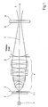
- the assemblies according to Figure 1 essentially comprise a lighting device 1, a sample holder 2 with a sample 2.1, which is positioned in or near the object plane 3, an objective 4 and a CCD camera 5 as a spatially resolving detection device, in or near the image plane 6 of the lens 4 is positioned.
- the assemblies have a common optical axis 7, which is not necessarily rectilinear.
- the assemblies are adjusted in a first step to each other so that the image of the sample 2.1, which may be present both physically and in the form of an image on the receiving surface of the CCD camera 5 is possible.
- the receiving surface of the CCD camera 5 consists of an array of sensor elements (pixels), at whose output information about the intensity of the incident, influenced by the sample, illumination light can be tapped.
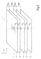
- images are taken from different defocus areas, which in their entirety result in a picture stack, as simplified in FIG Fig.2 shown.
- the individual illustrations are labeled A, B, C, D and E.
- the image stack extends in the direction of the optical axis 7 over a depth which corresponds to the sum of the plotted distances d ab to d de .
- the number of images is of course not limited to the number shown here, but essentially freely selectable. However, it is advisable to choose an odd number in order to achieve a targeted adjustment so that a representation from the best-focus plane and the remaining images from defocus areas can be obtained symmetrically to the best-focus level during defocusing.
- Each of the illustrated figures A to E consists of a grid of a plurality of image information arranged in rows i and columns j.
- These image information items are intensity values whose magnitude corresponds to the output signal of a respectively assigned sensor element (pixel) of the receiving surface of the CCD camera 5 and which represent the image of the sample.
- the image information A ij , B ij , C ij , D ij and E ij lying one behind the other in the direction of the optical axis 7 ideally relate to one and the same region of the sample, taken from different focal planes and thus also with different intensity values.
- the direction of the optical axis 7 corresponds to the coordinate direction Z of the ideally Cartesian coordinate system, while each of the maps lies in the plane spanned by the coordinates X and Y.
- the image information can be obtained with the aid of a VIS microscope, a UV microscope or another imaging system.
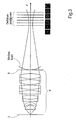
- the image stack can be picked up, for example, by adjusting the CCD camera 5 relative to the image plane 6, i. the images are taken during defocusing within the pictorial space.
- the distance between the sample 2.1 and the lens 4 remains unchanged.
- a pinhole in the sample 2.1 causes the intensity caustic as shown in FIG. 3 as a function of the different adjustment levels.
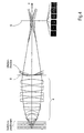
- the defocusing can also be achieved by changing the distance between the sample 2.1 and the objective 4, ie by defocusing in the object space, as shown in FIG.
- the distance between the receiving surface of the CCD camera 5 and the objective 4 or the pupil plane 8 remains constant.
- the quality of the images or the image information is improved by suppressing the noise according to known methods of image processing, only the intensity values are taken into account for the subsequent evaluation, which are above a threshold, filtered data and / or subjected to a smoothing become.
- each image is centered on a given location in the image, so that the intensity centers in each case lie on a straight line, for example in the positions A ij , B ij , C ij , D ij and E ij (see FIG.
- This provides a concrete proof of the imaging quality for the imaging system according to FIG.
- This proof can for example be handed over to the customer as a certificate with the delivery of a corresponding device for further use or made available to customer service.
- the quality for the customer can also be there on site of the imaging system can be determined and documented regularly or as needed.
- the method according to the invention has been explained primarily in connection with microscopic imaging systems. It should be noted, of course, that the application is also possible and advantageous in connection with other systems, in particular all finite-time imaging systems, such as binoculars, projectors, geodetic optical devices, camera systems, photographic equipment, medical observation equipment and, where appropriate, stepper technology. or scanner optics.
- finite-time imaging systems such as binoculars, projectors, geodetic optical devices, camera systems, photographic equipment, medical observation equipment and, where appropriate, stepper technology. or scanner optics.
- the application of the method according to the invention is possible for all optics that image a sample or an object.
- the method according to the invention is largely independent of the wavelength and can therefore be used in principle for all wavelengths.
- wavefront deformation used in the invention description refers to deviations from a given wavefront because it is not always desired that an imaging system produce a plane wavefront. This also applies in a figurative sense to the term "aberrations".
- the iteration proposed according to the invention should initially be carried out without additional parameters for the object space defocusing in order to arrive as quickly as possible in the range of the desired result values.
- the range of the result values is found, for example characterized by transition parameters such as the ratio of residuals to the signal-to-noise ratio in the respective image, number of iteration loops, iteration duration, slight deviation of the result of a current iteration cycle to the previous iteration cycle, etc.
- the Computing can be extended by parameters related to the object space defocusing, and at the same time the parameter space of the variable can be increased, in the case of the linear development of the object space defocusing can be doubled.
- the direct specification of the object space defocusing may disadvantageously also lead to errors due to the many parameters to be specified. For this reason too, it is initially possible to proceed iteratively without taking into account the object space defocusing, according to which object space defocusing is taken into account only in further, also iterative method steps. As a result, a better stability and convergence of the computing process can be achieved.
Abstract
Description
Die Erfindung bezieht sich auf ein Verfahren zur Bestimmung der Abbildungsgüte eines optischen Abbildungssystems, das im wesentlichen besteht aus Beleuchtungseinrichtung, Probenhalter mit Probe, Abbildungsoptiken und mindestens einer ortsauflösenden Detektionseinrichtung. Die Erfindung bezieht sich weiter auf die Nutzung des erfindungsgemäßen Verfahrens zur Ermittlung des Einflusses von Proben auf die Amplituden- und Phasenfrontverteilung des Beleuchtungslichts, von dem insbesondere die Amplitudenverteilung bekannt ist.The invention relates to a method for determining the imaging quality of an optical imaging system, which essentially consists of illumination device, sample holder with sample, imaging optics and at least one spatially resolving detection device. The invention further relates to the use of the inventive method for determining the influence of samples on the amplitude and phase front distribution of the illumination light, of which in particular the amplitude distribution is known.
Im Zusammenhang mit der Herstellung hochwertiger Abbildungsoptiken, insbesondere zur Anwendung in der Mikroskopie, ist eine Bewertung der erzielbaren Abbildungsgüte erforderlich.In connection with the production of high-quality imaging optics, in particular for use in microscopy, an evaluation of the achievable imaging quality is required.
Es ist bekannt, die Abbildungsgüte von Abbildungssystemen, die sowohl aus wenigen Linsen bestehen als auch komplexe optischen Baugruppen umfassen können, zumindest semiquantitativ zu bestimmen. Dazu ist es üblich, so genannte Sterntests durchzuführen, wobei kreisförmige Objekte unterhalb der Auflösungsgrenze der spezifischen Optik als Testproben verwendet werden. Anhand des Verhaltens der Beugungsfiguren bei der Abbildung dieser Proben mit Defokuseinstellungen und den darin enthaltenen Symmetrien kann die Güte der Abbildung bis zu einem meist ungenügenden Genauigkeitsgrad qualitativ bestimmt werden.It is known to determine the imaging quality of imaging systems, which may comprise both a few lenses and also comprise complex optical assemblies, at least semiquantitatively. For this purpose, it is customary to perform so-called star tests, wherein circular objects below the resolution limit of the specific optics are used as test samples. Based on the behavior of the diffraction patterns in imaging these samples with defocus settings and the symmetries contained therein, the quality of the image can be qualitatively determined to a mostly insufficient degree of accuracy.
So kann z.B. ein geschlossener erster Beugungsring am Rande des ersten Rayleighbereiches als Indiz für eine beugungsbegrenzte Optik betrachtet werden. Nachteiligerweise ist diese Bewertung lediglich als integrale Aussage zu verstehen. Und es kann auf diese Weise auch keine nähere quantitative Aussage über die Verteilung der restlichen Abbildungsfehler auf die verschiedenen Fehlertypen gewonnen werden, wie z.B. Sphäre, Koma oder Astigmatismus.Thus, e.g. a closed first diffraction ring on the edge of the first Rayleigh area be regarded as an indication of a diffraction-limited optics. Disadvantageously, this evaluation is to be understood only as an integral statement. And it can not be obtained in this way, any closer quantitative statement about the distribution of residual aberrations on the different types of errors, such. Sphere, coma or astigmatism.
Bei einer anderweitigen Verfahrensweise wird die Passe der einzelnen optischen Baugruppen interferometrisch geprüft, um so Aussagen über die geometrischen Fehler beispielsweise eines Linsenkörpers gewinnen zu können, die dann in systembedingte Abbildungsfehler umgerechnet werden.In another procedure, the pass of the individual optical assemblies is interferometrically tested in order to gain information about the geometric errors, for example, a lens body, which are then converted into system-related aberrations.
Hierbei werden bereits auch systematisch bedingte Einflußfaktoren erfaßt, sofern die Meßwellenlänge des Interferometers mit der Arbeitswellenlänge bzw. dem Wellenlängenspektrum des Beleuchtungslichts übereinstimmt. Bei aufwendigeren optischen Systemen werden gelegentlich auch speziell angepaßte Interferometer genutzt, um die Abbildungsgüte unter den gegebenen Randbedingungen und bei korrekter Arbeitswellenlänge, bezogen auf das gesamte Abbildungssystem, zu prüfen.In this case, systematically conditioned influencing factors are already detected, provided that the measuring wavelength of the interferometer coincides with the working wavelength or the wavelength spectrum of the illuminating light. For more complex optical systems occasionally specially adapted interferometers are used to test the image quality under the given conditions and at the correct operating wavelength, based on the entire imaging system.
Angewendet wird dies beispielsweise bei Abbildungsobjektiven für Stepper oder Scanner, die in der Halbleitermikrolithographie eingesetzt werden sollen. Diese Verfahrensweise erfordert einen verhältnismäßig hohen technischen Aufwand, ist dadurch sehr kostenintensiv und wird deshalb in Verbindung mit der Mikroskopfertigung meist nicht genutzt.This is used, for example, for imaging objectives for steppers or scanners, which are to be used in semiconductor microlithography. This procedure requires a relatively high technical effort, is therefore very costly and is therefore usually not used in conjunction with the production of microscopy.
Bekannt ist es weiterhin, die Wellenfront von optischen Abbildungssystemen mit sogenannten Hartmann- oder Shack-Hartmann-Wellenfrontsensoren oder mit Sensoren, die ein ähnliches Wirkungsprinzip haben, zu vermessen. Auch hier ist ein verhältnismäßig hoher technischer Aufwand zu betreiben, weshalb die entsprechenden Meßsysteme meist nur so ausgelegt sind, daß die Messungen lediglich für unterschiedliche Teilsysteme vorgesehen sind, die jedoch ähnliche Schnittstellen aufweisen, wie etwa Mikroobjektive für die Mikroskopie.It is also known to measure the wavefront of optical imaging systems with so-called Hartmann or Shack-Hartmann wavefront sensors or with sensors that have a similar mode of action. Again, a relatively high technical effort to operate, which is why the corresponding measurement systems are usually only designed so that the measurements are provided only for different subsystems, however, have similar interfaces, such as micro-lenses for microscopy.
In diesem Zusammenhang besteht insbesondere für Mikroskophersteller immer wieder das Problem, daß kein allgemeines Prüfverfahren verfügbar ist, das es ermöglicht, für die unterschiedlichsten optischen Abbildungssysteme, die sich durch optische, geometrische und mechanische Parameter unterscheiden, die Abbildungsgüte möglichst genau zu bestimmen.In this context, there is always the problem, in particular for microscope manufacturers, that no general test method is available which makes it possible to determine the imaging quality as accurately as possible for the most diverse optical imaging systems, which differ by optical, geometrical and mechanical parameters.
Auch besteht dieses Problem nicht nur während des Herstellungs- bzw. Justierprozesses, sondern auch im Zusammenhang mit der Überwachung der Qualität von Abbildungssystemen, die bereits beim Kunden im Einsatz sind.Also, this problem exists not only during the manufacturing or adjustment process, but also in the context of monitoring the quality of imaging systems already in use by the customer.
Weiterhin ist in all den bisher bekannten Verfahrensweisen die Ermittlung der Abbildungsgüte für mehrere Feldpositionen des Abbildungssystems aufwendig bzw. ungenau.Furthermore, in all the methods known hitherto, the determination of the imaging quality for a plurality of field positions of the imaging system is complicated or inaccurate.
Als Literaturquellen in diesen Zusammenhang seien genannt: Joseph Geary "Wavefront sensors", SPIE Press 1995 und Daniel Malacara "Optical Shop Testing", Wiley Verlag 1992.Literature sources in this context include: Joseph Geary "Wavefront sensors", SPIE Press 1995 and Daniel Malacara "Optical Shop Testing", Wiley Verlag 1992.
Von diesem Stand der Technik ausgehend liegt der Erfindung die Aufgabe zugrunde, die bisher bekannten Verfahren so weiterzuentwickeln, daß mit geringem technischen Aufwand eine genauere quantitative Bestimmung der Abbildungsgüte von optischen Abbildungssystemen möglich ist, und das Ergebnis der Abbildungsgüte-Bestimmung auch zur Ermittlung des Einflusses von zunächst unbekannten Proben auf die Amplituden- und Phasenfrontverteilung des Beleuchtungslichts Phasenfrontverteilung des Beleuchtungslichts, von dem insbesondere die Amplitudenverteilung bekannt ist, genutzt werden kann.Based on this prior art, the present invention seeks to further develop the previously known methods so that a more accurate quantitative determination of the imaging quality of optical imaging systems is possible with little technical effort, and the result of the mapping quality determination also to determine the influence of initially unknown samples on the amplitude and phase front distribution of the illumination light phase front distribution of the illumination light, of which in particular the amplitude distribution is known, can be used.
Erfindungsgemäß sind bei einem Verfahren der eingangs genannten Art folgende Verfahrensschritte vorgesehen:
- Justierung der Baugruppen zueinander so, daß Abbildungen einer Probe auf die Detektionseinrichtung möglich sind,
- Aufnehmen mehrerer Abbildungen der Probe aus verschiedenen Einstellebenen nahe der Fokusebene, wobei jeweils die Detektionseinrichtung relativ zur Bildebene, die Probe relativ zur Objektebene oder das Objektiv relativ zur Probe verstellt wird,
- Verbesserung der Bildqualität durch Bildbearbeitung, insbesondere zur Verringerung des Rauschens, zum Ausgleich lokaler Empfindlichkeitsunterschiede der Detektionseinrichtung und zur Zentrierung der Intensitätsschwerpunkte auf jeweils einen vorgegebenen Ort in den Abbildungen,
- rechnerische Verknüpfung der ortsaufgelösten Bildinformationen, der auf das optische Abbildungssystem bezogenen Einstellwerte und Systemgrößen sowie von Informationen zur Probe mit dem Ziel der Ermittlung von Kennzahlen, die charakteristisch sind für die durch das Abbildungssystem verursachte Wellenfrontdeformation, und
- Ausgabe der Kennzahlen und Zuordnung zum Abbildungssystem zur Beschreibung der Abbildungsgüte
- wobei als Kennzahlen Zernike-Koeffizienten, die jeweils einer Einstellebene zugeordnet sind, ausgegeben werden.
- Adjusting the assemblies to each other so that images of a sample on the detection device are possible,
- Recording a plurality of images of the sample from different adjustment planes near the focal plane, wherein in each case the detection device is adjusted relative to the image plane, the sample relative to the object plane, or the objective relative to the sample,
- Improvement of the image quality by image processing, in particular to reduce the noise, to compensate for local sensitivity differences of the detection device and to center the intensity centers on a respective predetermined location in the images,
- computational linkage of the spatially resolved image information, the setting values and system variables related to the optical imaging system as well as information on the sample with the aim of determining characteristic numbers, which are characteristic of wavefront deformation caused by the imaging system, and
- Output of the key figures and assignment to the imaging system to describe the image quality
- wherein Zernike coefficients, which are each assigned to a setting level, are output as characteristic numbers.
Grundsätzlich besteht der Erfindungsgedanke darin, zunächst mit dem betriebsbereiten optischen Abbildungssystem, von dem Abbildungsparameter wie Wellenlänge, numerische Apertur, Sigma (als Kohärenzgrad der Beleuchtung), Abtastung, Bildgröße (in Pixeln), Vergrößerung usw. bekannt sind oder bestimmt werden können, von einer Probe, bevorzugt einer Probe mit einem Pinhole, mehrere Aufnahmen, einen so genannten Bildstapel, zu gewinnen, wobei die einzelnen Aufnahmen dieses Bildstapels aus unterschiedlichen Fokusabständen, d.h. aus unterschiedlichen Defokuseinstellungen nahe der Fokusebene stammen.Basically, the inventive idea is to be informed first of all by the ready-to-use optical imaging system of which imaging parameters such as wavelength, numerical aperture, sigma (degree of coherence of illumination), scan, image size (in pixels), magnification etc. can be determined Sample, preferably a sample with a pinhole, several images, a so-called image stack to win, the individual shots of this image stack from different focal distances, ie come from different defocus settings near the focal plane.
Mit anderen Worten: Die Probe wird mehrfach mit jeweils veränderter Defokussierung auf die ortsauflösende Detektionseinrichtung abgebildet, und die dabei pixelweise gewonnenen Bildinformationen werden gespeichert. Damit steht ein Stapel aus übereinanderliegenden Schichtbildern zur Verfügung, bei dem jedes Bild aus einer Vielzahl von Bildinformationen in Form von Intensitätswerten besteht.In other words, the sample is imaged several times with changed defocusing in each case onto the spatially-resolving detection device, and the image information obtained pixel by pixel is stored. This provides a stack of superposed layer images in which each image consists of a plurality of image information in the form of intensity values.
Die einzelnen Bilder des Bildstapels werden zunächst Maßnahmen zur Verbesserung der Bildqualität unterzogen, die auf dem technischen Gebiet der Bildbearbeitung an sich bekannt sind. Diese Maßnahmen beziehen sich insbesondere
- auf die Verringerung des Rauschens bzw. die Verbesserung des Signal-Rausch-Verhältnisses,
- auf den Ausgleich lokaler Empfindlichkeitsunterschiede der einzelnen Sensorelemente (Pixel) der Detektionseinrichtung,
- auf die Linearisierung des Dynamikbereichs der Sensorelemente,
- auf den Abzug von Rausch-Untergrund,
- auf die Zentrierung der Intensitätsschwerpunkte in den einzelnen Abbildungen auf jeweils einen vorgegebenen Ort, und/oder
- auf das Ausschneiden von relevanten Bildanteilen, etwa von Achs- und Feldpunkten unter Vermeidung von Randbeschnitt.
- on the reduction of the noise or the improvement of the signal-to-noise ratio,
- to compensate for local sensitivity differences of the individual sensor elements (pixels) of the detection device,
- on the linearization of the dynamic range of the sensor elements,
- on the deduction of noise underground,
- on the centering of the focal points of intensity in the individual images on a given location, and / or
- on the cutting out of relevant image parts, such as axis and field points while avoiding edge trimming.
Diese Maßnahmen zur Verbesserung der Bildqualität sind insbesondere im Hinblick auf die mit den weiteren erfindungsgemäßen Verfahrensschritten erzielbare Genauigkeit von Vorteil.These measures for improving the image quality are particularly advantageous in view of the achievable with the further process steps according to the invention accuracy.
Nach der Verbesserung der Bildqualität werden die Bildinformationen sowie alle relevanten Daten, wie auf das optische Abbildungssystem bezogene Einstellwerte und Systemgrößen sowie Informationen zur Probe (Probentyp, Probeneigenschaften) zur Verknüpfung anhand vorgegebener Rechenprogramme an eine Auswerteeinrichtung übergeben.After the image quality has been improved, the image information as well as all relevant data, such as setting values and system variables related to the optical imaging system and information on the sample (sample type, sample properties) are transferred to an evaluation device for linking by means of predetermined computer programs.
Mit der Übergabe an die Auswerteeinrichtung wird zugleich optional entschieden, ob eine Entfaltung der Bildinformationen vorzunehmen ist, um die Probeneinflüsse von den Einflüssen des Abbildungssystems und der Beleuchtung zu trennen. Diese Entscheidung wird beispielsweise in Abhängigkeit von dem Durchmesser eines Pinholes dPH in der Probe im Vergleich zu dem objektseitigen Airy-Durchmesser dAiry des Abbildungssystems und der zu erzielenden Genauigkeit getroffen. Die entsprechenden Steuerparameter zur Entfaltung, wie Pinholedurchmesser oder z.B. Parameter zu einer Tikhonov-Regularisierung, werden im Falle der Entscheidung zur Entfaltung ebenfalls in die Auswerteeinrichtung eingegeben.With the transfer to the evaluation device, it is optionally optionally decided whether an unfolding of the image information is to be carried out in order to separate the sample influences from the influences of the imaging system and the illumination. This decision is made, for example, as a function of the diameter of a pinhole d PH in the sample in comparison to the object-side Airy diameter d Airy of the imaging system and the accuracy to be achieved. The corresponding control parameters for unfolding, such as pinhole diameter or, for example, parameters for a Tikhonov regularization, are also entered into the evaluation device in the case of the decision to unfold.
Weiterhin sind vor der Auswertung festzulegen bzw. für die Auswertung vorzugeben:
- die gewünschte Genauigkeit der Auswertung bzw. des Auswerteergebnisses,
- die Anzahl der Kennzahlen, die bei der Bewertung der Abbildungsgüte bestimmt bzw. zugrunde gelegt werden sollen,
- die Auswahl eines zur Auswertung zu nutzenden Rechenprogrammes aus einem Vorrat verfügbarer Rechenprogramme,
- Abbruchkriterien für die Auswertung, beispielsweise die Größe des Restfehlers, die Zahl von Iterationszyklen oder die Dauer der Auswertung,
- ob die Auswertung einstufig oder mehrstufig erfolgen soll, wobei mit der mehrstufigen Auswertung das Ziel verfolgt wird, schneller zum Ergebnis zu kommen, die Konvergenz zu erhöhen und den Ablauf zu stabilisieren, und
- ob während der Auswertung die Defokussierung im Objektraum, d.h. die Verstellung der Probe relativ zur Objektebene oder auch die Verstellung des Objektivs relativ zur Probe berücksichtigt werden soll; in diesem Falle ist beispielsweise der Parameterraum für eine vorzusehende Iterationsberechnung zu erhöhen, damit Einflüsse, die von der Objektraumdefokussierung stammen, berücksichtigt werden können.
- the desired accuracy of the evaluation or of the evaluation result,
- the number of key figures that are to be determined or used in the evaluation of the image quality,
- the selection of a computer program to be used for evaluation from a supply of available computer programs,
- Abort criteria for the evaluation, for example the size of the residual error, the number of iteration cycles or the duration of the evaluation,
- whether the evaluation should be one-stage or multi-stage, with the multi-stage evaluation aiming at faster results, increasing convergence and stabilizing the process, and
- whether the defocusing in the object space, ie the adjustment of the sample relative to the object plane or also the adjustment of the objective relative to the sample, is to be taken into account during the evaluation; In this case, for example, the parameter space for an iteration computation to be provided is to be increased, so that influences which originate from the object space defocusing can be taken into account.
In einer weiteren Ausgestaltung des Verfahrensablaufs können Pupillenfunktionen berücksichtigt werden, wie beispielsweise Ergebnisse der Messung der realen Ausleuchtung über eine Pupillenabbildung mittels eines Bertrandsystems oder die theoretisch bestimmbare Apodisierung der Pupille als Eigenschaft des Designs des Abbildungssystems.In a further embodiment of the method sequence, pupil functions can be taken into account, such as, for example, results of the measurement of the real illumination via pupil imaging by means of a Bertrands system or the theoretically determinable apodization of the pupil as a property of the design of the imaging system.
In einer besonders bevorzugten Ausgestaltung der Erfindung ist vorgesehen, daß die Ermittlung der Kennzahlen in einem ersten Schritt durch analytische Auswertung und in einem nachfolgenden zweiten Schritt durch iterative Auswertung erfolgt, wobei die Ergebnisse aus dem ersten Schritt als Startwerte in den zweiten Schritt übergeben und dort weiter verarbeitet werden, bis ein vorgegebenes Abbruchkriterium erreicht ist.In a particularly preferred embodiment of the invention, it is provided that the determination of the key figures in a first step by analytical evaluation and in a subsequent second step by iterative evaluation, wherein the results from the first step as starting values in the second step and passed there on are processed until a predetermined termination criterion is reached.
Der erste Schritt dient zum schnellen Auffinden des Zielbereichs der Ergebnisse für die Kennzahlen mit einem robusten Verfahren, kann allerdings bereits Ergebnisse mit begrenzter Genauigkeit liefern. Der zweite Schritt, der auf den noch ungenauen Ergebnissen des ersten Schrittes basiert bzw. diese als Startwerte nutzt, dient zur Ermittlung genauerer Ergebnisse.The first step is to quickly locate the target area of the results for the measures with a robust method, but can already deliver results with limited accuracy. The second step, which is based on the still inaccurate results of the first step or uses them as starting values, serves to determine more accurate results.
Im ersten, analytischen Schritt wird zunächst ein erster Satz Kennzahlen bestimmt, die für die Abbildungsgüte äquivalent sind, in Form von Zernike-Polynomen bis zu einer gewünschten Ordnung. Dazu werden die in die Auswertung eingebrachten Informationen bzw. Daten beispielsweise nach dem Extended-Zernike-Verfahren analysiert.In the first, analytical step, a first set of index numbers equivalent to the mapping quality, in the form of Zernike polynomials up to a desired order, is first determined. For this purpose, the information or data introduced into the evaluation is analyzed, for example, according to the Extended Zernike method.
Die sich mit der analytischen Auswertung ergebenden Kennzahlen genügen in der Regel noch nicht den Anforderungen an die Genauigkeit bei der Bewertung der Abbildungsgüte eines optischen Abbildungssystems. Deshalb ist der analytischen Bestimmung eine iterative Weiterbearbeitung nachgeordnet.The characteristic values resulting from the analytical evaluation generally do not yet meet the requirements for accuracy in the evaluation of the imaging quality of an optical imaging system. Therefore, the analytical determination is subordinated to an iterative processing.
In den iterativen Auswerteprozeß fließen im wesentlichen ein die Bildinformationen, die Bildaufnahmeparameter des optischen Abbildungssystems, die im vorhergehenden Schritt der analytischen Auswertung ermittelten Kennzahlen zur Abbildungsgüte und Residuen als Restfehler zwischen retrievalter und gemessener Intensitätsverteilung.In the iterative evaluation process flow essentially one of the image information, the image acquisition parameters of the optical imaging system, the figures determined in the previous step of the analytical evaluation to the image quality and residuals as a residual error between retrievalter and measured intensity distribution.
Die iterative Phase der Auswertung kann entweder pixelweise mit Fehlerminimierung, z.B. anhand von Meritfunktionen oder abgeleiteten Verfahrensvarianten, oder flächig (den Bildinhalt berücksichtigend) vorgenommen werden. Bevorzugt wird die Verwendung iterativer Verfahren nach Gerchberg bzw. nach dem Gerchberg-Saxton-Prinzip, dem wahlweise Optimierungsverfahren nach Levenberg-Marquardt, Gauß oder der non-least-square-Methode zugeordnet werden, die der Fachwelt bekannt sind.The iterative phase of the evaluation can either be done pixel by pixel with error minimization, e.g. based on merit functions or derived process variants, or flat (taking into account the image content). The use of iterative methods according to Gerchberg or according to the Gerchberg-Saxton principle, the optional optimization method according to Levenberg-Marquardt, Gauss or the non-least-square method, which are known to the experts, is preferably assigned.
Daneben ist es auch denkbar, der iterativen Auswertung keine analytische Auswertung voranzustellen, sondern die Bildinformationen sowie Angaben zum Abbildungssystem unmittelbar der iterativen Auswertung zuzuführen, wobei bevorzugt die probenunabhängigen und gegebenenfalls entfalteten Bildinformationen zu berücksichtigen sind. Allerdings hat die Vorschaltung der analytischen Auswertung den wesentlichen Vorteil, daß für die Iteration Startwerte verfügbar sind, die die Konvergenz und die Sicherheit, das gesuchte absolute Minimum der Residuen wirklich zu finden, deutlich erhöhen.In addition, it is also conceivable to provide the iterative evaluation with no analytical evaluation, but to supply the image information and information on the imaging system directly to the iterative evaluation, in which case the sample-independent and possibly unfolded image information should preferably be taken into account. However, the preliminary advantage of the analytical evaluation has the significant advantage that starting values are available for the iteration, the convergence and the safety, the sought absolute To really find minimum of residuals, increase significantly.
Wird die Defokussierung bei der Aufnahme des Bildstapels im Objektraum vorgenommen und soll die Objektraumdefokussierung bei der Auswertung auch berücksichtigt werden, so ist der Parameterraum für die Iteration zu erhöhen, bevorzugt in linearer Entwicklung zu verdoppeln, damit jeder Kennzahl für die Abbildungsgüte ein oder mehrere den Defokus beschreibende Parameter zugeordnet werden können und so die Defokuseffekte bei der Iteration berücksichtigt werden. Die Kennzahlen haben dann im linearen Fall jeweils die Form ![]()
mit ci,f der Kennzahl der Abbildungsgüte, Δz der Zustellung in Richtung der optischen Achse und ci,d einem Defokustherm.If the defocusing is performed when the image stack is taken in the object space and the object space defocusing is also to be taken into account during the evaluation, the parameter space for the iteration should be increased, preferably doubled in linear development, so that each characteristic figure for the image quality one or more defocus descriptive parameters can be assigned and so the defocus effects are taken into account during the iteration. The key figures then have the form in a linear case ![]()
with c i, f of the figure of merit of the imaging quality, Δz of the delivery in the direction of the optical axis and c i, d a Defokustherm.
Die Daten und Informationen, die der Iteration zugrunde zu legen sind, können wahlweise aus unterschiedlichen vorangegangenen Stufen der Meßwertermittlung oder dem Ergebnis theoretischer Systemberechnung übernommen werden.The data and information to be used for the iteration may optionally be taken from different previous stages of the measured value determination or the result of theoretical system calculation.
Um die Auswertung robust und sicher bzw. störunanfällig zu gestalten, können in die iterative Auswertung bekannte global optimierende Verfahren einbezogen werden, beispielsweise "simulated annealing", oder auch selbstlernende Rechenvorgänge.In order to make the evaluation robust and safe or immune to interference, known global optimizing methods can be included in the iterative evaluation, for example "simulated annealing" or even self-learning computational processes.
Die Ausgabe des Auswerteergebnisses ist vorgesehen in Form von Kennzahlen, die die Abbildungsgüte beschreiben, als Zernike-Koeffizienten, als Bildinformationen, in Form von Residuen als Restfehler zwischen retrievalter und gemessener Intensitätsverteilung und als den ermittelten Zernike-Koeffizienten zugeordneten Defokusparameter.The output of the evaluation result is provided in the form of characteristic numbers which describe the image quality, as Zernike coefficients, as image information, in the form of residuals as a residual error between retrievalter and measured intensity distribution and defocus parameters associated with the determined Zernike coefficients.
Das erfindungsgemäße Verfahren wird weiter dahingehend verwendet, die mit der Abbildungsgüte nun auch bekannten Abbildungsfehler aus den Bildern herauszurechnen, die von beliebigen, zunächst noch unbekannten Proben mit demselben Abbildungssystem aufgenommen werden.The method according to the invention is further used to calculate the imaging errors which are now also known from the images, which are recorded by arbitrary, initially unknown samples with the same imaging system.
Dazu werden die mit der zunächst noch unbekannten Probe gewonnenen Bildinformationen einer Nachbearbeitung unterworfen, in der die Eigenschaften des Abbildungssystems durch Herausfaltung berücksichtigt werden. Auf diese Weise werden bei der Probenabbildung die spezifischen Geräteeigenschaften berücksichtigt und zugleich auch korrigiert. Vorteilhaft ist es, bei der Herausfaltung der Eigenschaften des Abbildungssystems aus den Probenbildern zugleich auch den Einfluß der endlichen Objektgröße aus den Punktbildern zu korrigieren.For this purpose, the image information obtained with the initially unknown sample is subjected to a post-processing, in which the properties of the imaging system are taken into account by unfolding. In this way, the specific device properties are considered and at the same time corrected during sample imaging. It is advantageous to correct the unfolding of the properties of the imaging system from the sample images at the same time also the influence of the finite object size from the dot images.
Auf diese Weise ist es ebenso möglich, den Einfluß beispielsweise eines Steppers in der Mikrolithographie in die Eigenschaften eines Bildes wieder per Faltung einzurechnen, um die Eigenschaften des Meßsystems zu korrigieren und so ein Bild zu erhalten, wie es der Stepper erzeugt hätte.In this way it is also possible to recalculate the influence of, for example, a stepper in microlithography in the properties of an image by folding in order to correct the properties of the measuring system and to obtain an image as the stepper would have produced.
Die Änderung der Einstellebene zur Aufnahme des Bildstapels sollte vorteilhaft in vorzugebenden Schritten erfolgen.The change of the adjustment level for receiving the image stack should advantageously take place in predetermined steps.
Der Bildstapel kann mittels einer einzelnen ortsauflösenden Detektionseinrichtung aufgenommen werden, wobei jeweils eine Verstellung der Detektionseinrichtung oder der Probe erforderlich ist. Alternativ ist es aber auch möglich, zur Aufnahme des Bildstapels mehrere ortsauflösende Detektionseinrichtungen zu nutzen, die dann jeweils in den gewünschten Einstellebenen anzuordnen sind. Im letzteren Falle ist sowohl die gleichzeitige Aufnahme aller Abbildungen des Bildstapels als auch, je nach Ansteuerung, die zeitliche aufeinanderfolgende Aufnahme der zu einem Bildstapel gehörenden Abbildungen möglich.The image stack can be recorded by means of a single spatially resolving detection device, wherein an adjustment of the detection device or the sample is required in each case is. Alternatively, however, it is also possible to use a plurality of spatially resolving detection devices for recording the image stack, which are then each to be arranged in the desired adjustment planes. In the latter case, both the simultaneous recording of all images of the image stack and, depending on the control, the temporal successive recording of the images belonging to a picture stack is possible.
Soll die Abbildungsgüte bezogen auf verschiedene Positionen im Gesichtsfeld des Abbildungssystems ermittelt werden, so kann in einer Ausgestaltung der Erfindung vorgesehen sein, daß der Bestimmung der Kennzahlen mehrere Proben zugrunde gelegt werden, die nebeneinander in der Probenhalterung positioniert sind. So liefern die Proben für jede Aufnahme Bildinformationen, die den jeweiligen Positionen zugeordnet werden können.If the imaging quality with respect to different positions in the field of view of the imaging system is to be determined, it can be provided in one embodiment of the invention that the determination of the characteristic numbers is based on several samples which are positioned next to one another in the sample holder. Thus, the samples provide image information for each shot, which can be assigned to the respective positions.
Ebenso ist es möglich, eine Probe mit mehreren Objekten im Gesichtsfeld des Abbildungssystems anzuordnen, um so in einem Bildstapel Informationen über die Bildfehler im Gesichtsfeld zu ermitteln. Bei der Auslegung der Probe in Bezug auf die Eigenschaften des Abbildungssystems ist es vorteilhaft darauf zu achten, daß sich die Objekte in der Anordnung gegenseitig nicht beeinflussen.It is also possible to arrange a sample with a plurality of objects in the field of view of the imaging system in order to determine information about the image errors in the field of view in an image stack. When designing the sample with respect to the properties of the imaging system, it is advantageous to ensure that the objects in the array do not interfere with each other.
Als Proben kommen dabei binäre Objekte, d.h. reine Amplitudenobjekte, wie z.B. Lithographiemasken in Betracht.The samples are binary objects, i. pure amplitude objects, such as e.g. Lithography masks into consideration.
In einer weiteren, besonders bevorzugten Ausgestaltung der Erfindung ist vorgesehen, daß die Ermittlung aller in die Auswertung einfließenden Daten und Informationen sowie auch die Auswertung einschließlich der Ausgabe der Auswerteergebnisse automatisch ablaufen.In a further, particularly preferred embodiment of the invention, it is provided that the determination of all data and information flowing into the evaluation and also the evaluation, including the output of the evaluation results, takes place automatically.
Unter Umständen ist es vorteilhaft, bei der Gewinnung des Bildstapels eine Belichtungssteuerung zu verwenden, die trotz der veränderten Einstellebenen jeweils eine optimale Ausleuchtung der Probe gewährleistet, wodurch bereits während der Aufnahme das Signal-Rausch-Verhältnis in den Bildern optimiert wird.Under certain circumstances, it is advantageous to use an exposure control in the extraction of the image stack, which guarantees optimum illumination of the sample despite the changed adjustment levels, whereby the signal-to-noise ratio in the images is already optimized during recording.
Auch ist es denkbar, zur Ausleuchtung der Probe eine Laserstrahlung zu nutzen, die in der Objektebene eine Strahltaille aufweist, was typischer Weise zu einem niedrigen Sigma-Wert und auch zu einer gauß'schen Intensitätsverteilung in der Pupille des Abbildungssystems führt.It is also conceivable, for illuminating the sample, to use laser radiation which has a beam waist in the object plane, which typically leads to a low sigma value and also to a Gaussian intensity distribution in the pupil of the imaging system.
In einer Weiterentwicklung des erfindungsgemäßen Verfahrens ist die Bestimmung des Einflusses von zunächst noch unbekannten Proben auf die Amplituden- und Phasenfrontverteilung des Beleuchtungslichts, von dem diese Verteilung bekannt ist, mit folgenden Verfahrensschritten vorgesehen:
- Bestimmung der für das optische Abbildungssystem charakteristischen Wellenfrontdeformation anhand einer bezüglich ihrer Eigenschaften bekannten Probe,
- Austausch dieser Probe gegen eine zu untersuchende Probe mit zunächst noch unbekannten Eigenschaften,
- erneute Bestimmung der Wellenfrontdeformation unter Berücksichtigung des Einflusses der zu untersuchenden Probe nach den vorangehend dargelegten Verfahrensschritten,
- Trennung der Kennzahlen für die Abbildungsgüte, die sich unter Einfluß der unbekannten Probe ergeben haben, und der Kennzahlen für die Abbildungsgüte, die ohne Einfluß der unbekannten Probe ermittelt worden sind, und
- Bestimmung der Eigenschaften der zunächst unbekannten Probe aus dem Ergebnis dieser Trennung.
- Determination of the wavefront deformation characteristic of the optical imaging system on the basis of a sample known with respect to its properties,
- Replacement of this sample against a sample to be investigated with initially unknown properties,
- re-determination of the wavefront deformation, taking into account the influence of the sample to be examined according to the method steps set out above,
- Separation of the figures for the image quality, which have resulted under the influence of the unknown sample, and the characteristics of the image quality, which have been determined without influence of the unknown sample, and
- Determination of the properties of the initially unknown sample from the result of this separation.
Die derartige Bestimmung der Eigenschaften von Proben schließt an die bisherigen Verfahrensschritte an und geht von einem betriebsbereiten optischen Abbildungssystem aus, für das die für die Abbildungsgüte charakteristischen Kennzahlen bereits vorliegen. Zu diesem Abbildungssystem sind auch die Abbildungsparameter bekannt bzw. können bestimmt werden, wie Wellenlänge des Beleuchtungslichts, numerische Apertur, Sigma, Abtastung, Vergrößerung, Bildgröße (in Pixeln) und Defokusparameter (zugeordnet zu den Kennzahlen für die Abbildungsgüte).The determination of the properties of samples in this way follows the previous method steps and is based on an operational optical imaging system for which the characteristics characteristic of the imaging quality are already present. The imaging parameters are also known or can be determined for this imaging system, such as wavelength of the illumination light, numerical aperture, sigma, scanning, magnification, image size (in pixels) and defocus parameters (assigned to the imaging quality figures).
In dieses Abbildungssystem mit bekannten Abbildungseigenschaften wird eine zu untersuchende, noch unbekannte Probe eingelegt oder ein Bild einer Probe einprojeziert. Von der zu untersuchenden Probe wird eine Serie von Abbildungen, also wiederum ein Bildstapel, aufgenommen. Auch hier wird für jede Abbildung der Fokusabstand geändert wie bereits beschrieben, wobei auch hier eine defokusabhängige Belichtungssteuerung genutzt werden kann, um die Ausleuchtung der Probe an die jeweilige Fokusebene anzupassen.In this imaging system with known imaging properties is placed to be examined, a still unknown sample or einprojeziert an image of a sample. From the sample to be examined, a series of images, ie in turn an image stack, is recorded. Again, the focus distance is changed for each image as already described, with a defocus-dependent exposure control can also be used here to adjust the illumination of the sample to the respective focal plane.
Die so von der zu untersuchenden Probe gewonnenen Bilder werden hinsichtlich ihrer Qualität aufgearbeitet, wobei wiederum das Signal-Rausch-Verhältnisses etwa durch Dunkelbildkorrektur verbessert, eine Linearisierung der Pixel (flat fielding) vorgenommen, Rausch-Untergrund abgezogen, der Intensitätsschwerpunkt in jeder Abbildung zentriert, relevante Bildanteile ausgeschnitten und/oder eine Rauschfilterung vorgesehen werden können, so daß ein Bildstapel mit aussagefähigen, auswertbaren Bildern zur Weiterbearbeitung vorliegt.The images thus obtained from the sample to be examined are processed in terms of quality, whereby the signal-to-noise ratio, for example, is improved by dark image correction, flat-fielding, noise background subtracted, the center of gravity centered in each image, cut out relevant image portions and / or noise filtering can be provided so that an image stack is present with meaningful, evaluable images for further processing.
Dabei kann die Zentrierung des Intensitätsschwerpunktes unter Ausnutzung der im Bild enthaltenen Datenwerte direkt oder aber über Korrelation vorgenommen werden, da die Bilder jetzt (im Gegensatz zu der Aufnahme eines Bildstapels zur Bestimmung der Kennzahlen des reinen Abbildungssystems) nicht am Rand des Kamerafeldes enden, oder rein mechanisch vorgenommen werden, wenn zuvor der laterale Ablauf in X,Y-Richtung in Bezug auf die z-Position für das Abbildungssystem in der jeweiligen Ebeneneinstellung bestimmt worden ist, gegebenenfalls auch mit Interpolation von Zwischenebenen.In this case, the centering of the intensity center of gravity can be made directly or else via correlation using the data values contained in the image, since the images do not end at the edge of the camera field (or in contrast to the image stack for determining the characteristic numbers of the pure imaging system), or purely are made mechanically, if previously the lateral flow in the X, Y direction has been determined with respect to the z position for the imaging system in the respective plane setting, possibly also with interpolation of intermediate planes.
Die nach dieser Aufbereitung vorhandenen Bildinformationen, die Informationen zum Abbildungssystem, die Informationen zu der auf jede Abbildung bezogenen Einstellung sowie die Kennzahlen für die Abbildungsgüte werden nun an eine Auswerteeinrichtung übergeben.The image information available after this processing, the information on the imaging system, the information on the setting related to each image and the image quality indicators are now transferred to an evaluation device.
Für die Auswertung werden insbesondere vorgegeben:
- die gewünschte Genauigkeit der Auswertung bzw. des Auswerteergebnisses,
- die Anzahl der Kennzahlen zur Beschreibung der Abbildungsgüte, d.h. die Anzahl der Zernike-Koeffizienten, die der Auswertung bzw. dem Ergebnis zugrunde zu legen sind,
- Auswahl des zu verwendenden Rechenweges und Optimierungsverfahrens, sofern die Auswerteeinrichtung über mehrere geeignete Rechenalgorithmen verfügt,
- Vorgabe des Abbruchkriteriums für eine iterative Auswertung, wie beispielsweise Restfehler, Zahl der Iterationszyklen, Dauer der Auswertung,
- die einstufige oder mehrstufige Auswertung, wobei mit der mehrstufigen Auswertung das Ziel verfolgt wird, die Rechenzeit zu verkürzen, die Konvergenz und das sichere Finden des Ergebnisses bei der Iteration zu erhöhen oder auch den Rechenablauf zu stabilisieren,
- die Berücksichtigung einer eventuell vorgenommenen Objektraumdefokussierung, wozu dann der Parameterraum für die Iterationsberechtigung erhöht werden sollte, um eine Variation der Kennzahlen der Abbildungsgüte berücksichtigen zu können, die von der Objektraumdefokussierung stammen, sowie
- ein Kriterium für den Übergang von einer analytischen Auswertung zur einer iterativen Auswertung, wie beispielsweise Restfehler, Dauer der Auswertung usw.
- the desired accuracy of the evaluation or of the evaluation result,
- the number of figures describing the image quality, ie the number of Zernike coefficients to be used for the evaluation or the result,
- Selection of the calculation path to be used and the optimization method, if the evaluation device has several suitable calculation algorithms,
- Specification of the abort criterion for an iterative evaluation, such as residual error, number of iteration cycles, duration of the evaluation,
- the one-stage or multi-stage evaluation, whereby the multistage evaluation pursues the goal of shortening the computation time, increasing the convergence and the secure finding of the result in the iteration or also stabilizing the computational sequence,
- the consideration of a possibly made object space defocusing, for which purpose then the parameter space for the iteration authorization should be increased in order to be able to take into account a variation of the characteristics of the image quality, which originate from the object space defocusing, as well
- a criterion for the transition from an analytical evaluation to an iterative evaluation, such as residual error, duration of the evaluation, etc.
Erfindungsgemäß werden bei mehrstufiger Auswertung in einem ersten Schritt die Kennzahlen für die Abbildungsgüte des Abbildungssystems mit der noch unbekannten Probe wiederum analytisch bestimmt. Hierzu werden nach dem Extended-Zernike-Verfahren Zernike-Polynome bis zu einer gewünschten Ordnung ermittelt.According to the invention, the values for the imaging quality of the imaging system with the still unknown sample are again determined analytically in a first step in multi-stage evaluation. For this purpose, Zernike polynomials up to a desired order are determined by the Extended Zernike method.
In einem nachgeordneten zweiten Schritt der Auswertung erfolgt die iterative Bestimmung der Kennzahlen zur Abbildungsgüte, wobei die Ergebnisse der vorangegangen analytischen Auswertung als Startwerte für die Interation verwendet werden, um so die Konvergenz des Interationsverfahrens zu erhöhen.In a subsequent second step of the evaluation, the iterative determination of the characteristic numbers for the image quality takes place, the results of the preceding analytical evaluation being used as starting values for the interation so as to increase the convergence of the interagency process.
Eingangsgrößen für die iterative Stufe der Auswertung sind wiederum die Bildinformationen, die Kennzahlen zur Abbildungsgüte (d.h. in Form von Zernike-Koeffizienten) und zum Vergleich Residuen als Restfehler zwischen retrievalter und gemessener Intensitätsverteilung in den Bildern der Probe sowie gegebenenfalls die Systemparameter für die Defokussiereigenschaften.Input variables for the iterative stage of the evaluation are, in turn, the image information, the image quality indicators (i.e., in the form of Zernike coefficients) and, for comparison, residuals between the retriever and the measured intensity distribution in the images of the sample and, if appropriate, the system parameters for the defocusing properties.
Die Iteration kann hier wiederum entweder pixelweise mit Fehlerminimierung z.B. nach der Gerchberg-Saxton-Methode mit nachgeordneten Optimierungsverfahren, z.B. nach der non-least-square Methode, Levenberg-Marquardt o.ä. vorgenommen werden.Again, the iteration may be done either pixel by pixel with error minimization e.g. according to the Gerchberg-Saxton method with downstream optimization methods, e.g. according to the non-least-square method, Levenberg-Marquardt or similar be made.
Um die Auswertung robust und sicher bzw. störunanfällig zu gestalten, können in die iterative Auswertung bekannte global optimierende Verfahren einbezogen werden, beispielsweise "simulated annealing", oder auch selbstlernende Rechenvorgänge.In order to make the evaluation robust and safe or immune to interference, known global optimizing methods can be included in the iterative evaluation, for example "simulated annealing" or even self-learning computational processes.
Bevorzugt sind pixelweise iterierende Verfahren anzuwenden, da Informationen über eine zunächst noch unbekannte Probenstruktur gewonnen werden sollen. Die Anwendung der flächig iterierenden Verfahren ist bevorzugt bei Proben mit lediglich weitläufigen Strukturen und verhältnismäßig geringen Gradienten zu empfehlen, wie beispielsweise bei der Untersuchung einiger biologischer Proben.Pixel-wise iterating methods are preferably to be used since information about an initially unknown sample structure is to be obtained. The use of area iterating methods is preferred for samples with only extensive structures and relatively low gradients, such as in the study of some biological samples.
Eine Ausgestaltung des erfindungsgemäßen Verfahrens besteht darin, die Objektraumdefokussierung zu berücksichtigen und im Zusammenhang damit den Parameterraum für die Iteration zu vergrößern, so daß jeder für die Abbildungsgüte ermittelten Kennzahl Defokusparameter zugeordnet werden können und die Defokuseffekte bei der Iteration berücksichtigt sind. Hierbei können als Startwerte die Werte des Abbildungssystems alleine verwendet werden.An embodiment of the method according to the invention consists in considering the object space defocusing and, in connection therewith, increasing the parameter space for the iteration, so that defocus parameters can be assigned to each characteristic number determined for the image quality and the defocus effects are taken into account during the iteration. In this case, the values of the imaging system alone can be used as starting values.
Im Ergebnis der Auswertung liegen dann Kennzahlen der Abbildungsgüte des Abbildungssystems vor, die von der zu untersuchende Probe beeinflußt sind und die demzufolge von den Kennzahlen abweichen, die vorher mit einer bekannten Probe bestimmt worden sind.As a result of the evaluation are then figures of the imaging quality of the imaging system, which are influenced by the sample to be examined and thus deviate from the figures that have been previously determined with a known sample.
Zur Trennung der Probeneigenschaften von den Eigenschaften des Abbildungssystems kann nun wie folgt vorgegangen werden:
- 1. Es wird eine best-fokus-Bestimmung für den gewonnenen Bildstapel durchgeführt und basierend auf den Kennzahlen der Abbildungsgüte des Abbildungssystems eine simulierte Fokusserie einfachster Objektstrukturen, z.B. eines Punktbildes, einer Kante oder Spalte, nur für das Abbildungssystem an den Fokuspositionen des gemessenen Bildstapels berechnet. Durch Entfaltung der Bilder des gemessenen Bildstapels mit entsprechenden Bildern des simulierten Bildstapels werden die Bilder des gemessenen Bildstapels von den Eigenschaften des Abbildungssystems befreit. Aus diesem Bildstapel werden die Kennzahlen der Abbildungsgüte für die Probe alleine bestimmt. Mit den auf diese Weise ermittelten probenbezogenen Kennzahlen der Abbildungsgüte ist es möglich, auf die Amplituden-, Phasen- und/oder Intensitätsverteilung in der Objektebene für die Probe alleine zurückzurechnen, um so die Probeneigenschaften zu erhalten. Prinzipiell kann auch anstelle des simulierten Bildstapels eine gemessenen Bildserie verwendet werden, wobei allerdings mit geringerer Genauigkeit zu rechnen ist.
- 2. Die Kennzahlen des Abbildungssystems, wie sie nach dem eingangs beschriebenen Verfahrensschritten mit der bekannten Probe ermittelt worden sind, werden von den Kennzahlen des Abbildungssystems, die unter Einfluß der zu untersuchenden Probe ermittelt wurden, subtrahiert. Auf diese Weise werden die Probeneigenschaften separiert und können in geeigneter Form ausgegeben werden, beispielsweise in Form von Angaben zur räumlichen Amplituden- oder Intensitätsverteilung, zur räumlichen Phasenverteilung, als Iso-Amplituden, Iso-Intensitätsflächen oder Iso-Phasenflächen.
Insbesondere im Falle der pixelweisen Berechnungsmethoden kann ein "unwrapping" der Phasenflächen notwendig sein. Auch hier kann mit den so bestimmten probenbezogenen Kennzahlen der Abbildungsgüte noch auf die Amplituden-, Phasen- oder Intensitätsverteilung in der Objektebene zurückgerechnet werden, um die Probeneigenschaften zu präzisieren. - 3. Anhand der Kennzahlen der Abbildungsgüte für das Abbildungssystem mit der bekannten Probe einerseits und der Kennzahlen der Abbildungsgüte des Abbildungssystems ohne die zu untersuchende Probe andererseits werden die optischen Feldverteilungen in der Objektebene durch Rückrechnung bestimmt und entfaltet und die Angaben zu den Eigenschaften der Probe alleine gewonnen.
- 1. A best-focus determination is made for the image stack obtained and, based on the imaging quality of the imaging system, a simulated focus series of simplest object structures, eg a point image, an edge or a column, calculated only for the imaging system at the focus positions of the measured image stack , By unfolding the images of the measured image stack with corresponding images of the simulated image stack, the images of the measured image stack are freed from the properties of the imaging system. From this image stack, the characteristics of the image quality for the sample are determined alone. With the sample-related characteristic numbers of the image quality determined in this way, it is possible to calculate back to the amplitude, phase and / or intensity distribution in the object plane for the sample alone in order to obtain the sample properties. In principle, it is also possible to use a measured image series instead of the simulated image stack, although a lesser degree of accuracy is to be expected.
- 2. The characteristics of the imaging system, as they have been determined by the method described above with the known sample are subtracted from the characteristics of the imaging system, which were determined under the influence of the sample to be examined. In this way, the sample properties are separated and can be output in a suitable form, for example in the form of information on the spatial amplitude or intensity distribution, the spatial phase distribution, as iso-amplitudes, iso-intensity surfaces or iso-phase surfaces.
In particular, in the case of the pixel-by-pixel calculation methods, an unwrapping of the phase surfaces may be necessary. Here, too, with the thus determined sample-related characteristic numbers of the image quality, the amplitude, phase or intensity distribution in the object plane can be recalculated in order to specify the sample properties. - 3. On the basis of the figures of the image quality for the imaging system with the known sample on the one hand and the Key figures of the imaging quality of the imaging system without the sample to be examined on the other hand, the optical field distributions in the object plane are determined by re-calculation and unfolded and obtained the information on the properties of the sample alone.
Die Ergebnisausgabe erfolgt bevorzugt in Form von Bildinformationen, Kennzahlen zur Abbildungsgüte, d.h. Zernike-Koeffizienten, Defokusparametern zu den gemessenen Zernike-Koeffizienten, Angaben zur Amplitude, Phase oder Intensität, die auf den Einfluß der Probe zurückzuführen sind.The result output is preferably in the form of image information, image quality indicators, i. Zernike coefficients, defocus parameters for the measured Zernike coefficients, amplitude, phase or intensity data due to the influence of the sample.
Prinzipell erfolgt die Ergebnisausgabe bei den drei vorstehend angegebenen Varianten in derselben Weise, wobei jedoch in Abhängigkeit von der gewählten Variante verschiedenen Zusatzinformationen mit ausgegeben werden können.In principle, the result output in the three variants given above takes place in the same way, but depending on the selected variant, various additional information can also be output.
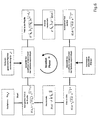
Das erfindungsgemäße Verfahren soll nachfolgend anhand eines Ausführungsbeispieles erläutert werden. In den zugehörigen Zeichnungen zeigen
- Fig.1
- eine prinzipielle Darstellung optischer Baugruppen, die in einem optischen Abbildungssystem genutzt werden,
- Fig.2
- die vereinfachte Darstellung eines Bildstapels, bestehend aus mehreren, aus unterschiedlichen Fokuseinstellungen von einer Probe gewonnenen Abbildungen,
- Fig.3
- ein Beispiel für die Aufnahme eines Bildstapels bei Defokussierung innerhalb des Bildraumes,
- Fig.4
- ein Beispiel für die Aufnahme eines Bildstapels bei Defokussierung innerhalb des Objektraumes,
- Fig.5
- Darstellung eines konkret ausgeführten optischen Abbildungssystems,
- Fig.6
- die prinzipielle Vorgehensweise bei der Auswertung durch Iteration, und
- Fig.7
- Nachweis der Abbildungsgüte eines optischen Abbildungssystems nach Fig.5 in Form einer Werte-Tabelle.
- Fig.1
- a schematic representation of optical components that are used in an optical imaging system,
- Fig.2
- the simplified representation of an image stack consisting of several images obtained from different focus settings of a sample,
- Figure 3
- an example of the inclusion of an image stack when defocused within the image space,
- Figure 4
- an example of the inclusion of an image stack when defocused within the object space,
- Figure 5
- Representation of a concretely executed optical imaging system,
- Figure 6
- the basic procedure for evaluation by iteration, and
- Figure 7
- Proof of the imaging quality of an optical imaging system according to FIG. 5 in the form of a values table.
Die Baugruppen nach Fig.1 umfassen im wesentlichen eine Beleuchtungeinrichtung 1, einen Probenhalter 2 mit einer Probe 2.1, die in oder nahe der Objektebene 3 positioniert ist, ein Objektiv 4 und eine CCD-Kamera 5 als ortsauflösende Detektionseinrichtung, die in oder nahe der Bildebene 6 des Objektivs 4 positioniert ist. Die Baugruppen haben eine gemeinsame optische Achse 7, die nicht notwendigerweise geradlinig verläuft.The assemblies according to Figure 1 essentially comprise a
Die Baugruppen werden in einem ersten Verfahrensschritt so zueinander justiert, daß die Abbildung der Probe 2.1, die sowohl körperlich als auch in Form einer Abbildung vorhanden sein kann, auf die Empfangsfläche der CCD-Kamera 5 möglich ist. Die Empfangsfläche der CCD-Kamera 5 besteht aus einem Array von Sensorelementen (Pixeln), an deren Ausgang Informationen über die Intensität des auftreffenden, von der Probe beeinflußten, Beleuchtungslichtes abgreifbar sind.The assemblies are adjusted in a first step to each other so that the image of the sample 2.1, which may be present both physically and in the form of an image on the receiving surface of the
In einem zweiten Verfahrensschritt werden aus unterschiedlichen Defokusbereichen Abbildungen aufgenommen, die in ihrer Gesamtheit einen Bildstapel ergeben, wie vereinfacht in Fig.2 dargestellt. Die einzelnen Abbildungen sind mit A, B, C, D und E bezeichnet. Der Bildstapel erstreckt sich in Richtung der optischen Achse 7 über eine Tiefe, die der Summe aus den eingezeichneten Abständen dab bis dde entspricht.In a second method step, images are taken from different defocus areas, which in their entirety result in a picture stack, as simplified in FIG Fig.2 shown. The individual illustrations are labeled A, B, C, D and E. The image stack extends in the direction of the optical axis 7 over a depth which corresponds to the sum of the plotted distances d ab to d de .
Die Anzahl der Abbildungen ist selbstverständlich nicht auf die hier dargestellte Anzahl beschränkt, sondern im wesentlichen frei wählbar. Allerdings ist zu empfehlen, eine ungerade Anzahl zu wählen, um so durch gezielte Einstellung zu erreichen, daß eine Abbildung aus der best-fokus-Ebene und die übrigen Abbildungen aus Defokusbereichen bei Defokussierung symetrisch zur best-fokus-Ebene gewonnen werden können.The number of images is of course not limited to the number shown here, but essentially freely selectable. However, it is advisable to choose an odd number in order to achieve a targeted adjustment so that a representation from the best-focus plane and the remaining images from defocus areas can be obtained symmetrically to the best-focus level during defocusing.
Jede der dargestellten Abbildungen A bis E besteht aus einem Raster aus einer Vielzahl von in Zeilen i und Spalten j angeordneten Bildinformationen. Diese Bildinformationen sind Intensitätswerte, deren Größe dem Ausgangssignal eines jeweils zugeordneten Sensorelementes (Pixels) der Empfangsfläche der CCD-Kamera 5 entspricht und die das Bild der Probe repräsentieren.Each of the illustrated figures A to E consists of a grid of a plurality of image information arranged in rows i and columns j. These image information items are intensity values whose magnitude corresponds to the output signal of a respectively assigned sensor element (pixel) of the receiving surface of the
In Fig.2 betreffen die in Richtung der optischen Achse 7 hintereinanderliegenden Bildinformationen Aij, Bij, Cij, Dij und Eij idealerweise ein und denselben Bereich der Probe, aufgenommen aus unterschiedlichen Fokusebenen und dadurch auch mit unterschiedlicher Intensitätswerten.2, the image information A ij , B ij , C ij , D ij and E ij lying one behind the other in the direction of the optical axis 7 ideally relate to one and the same region of the sample, taken from different focal planes and thus also with different intensity values.
Die Richtung der optischen Achse 7 entspricht dabei der Koordinatenrichtung Z des idealerweise kartesischen Koordinatensystems, während jede der Abbildungen in der von den Koordinaten X und Y aufgespannten Ebene liegt.The direction of the optical axis 7 corresponds to the coordinate direction Z of the ideally Cartesian coordinate system, while each of the maps lies in the plane spanned by the coordinates X and Y.
Prinzipiell können die Bildinformationen mit Hilfe eines VIS-Mikroskops, eines UV-Mikroskops oder eines anderen Abbildungssystems gewonnen werden.In principle, the image information can be obtained with the aid of a VIS microscope, a UV microscope or another imaging system.
Wie in Fig.3 gezeigt, kann die Aufnahme des Bildstapels beispielsweise dadurch erfolgen, daß die CCD-Kamera 5 relativ zur Bildebene 6 verstellt wird, d.h. die Aufnahmen werden bei Defokussierung innerhalb des Bildraumes gewonnen. Der Abstand zwischen der Probe 2.1 und dem Objektiv 4 bleibt dabei unverändert. Ein Pinhole in der Probe 2.1 verursacht dabei in Abhängigkeit von den unterschiedlichen Einstellebenen die Intensitätskaustik wie in Fig.3 dargestellt.As shown in Figure 3, the image stack can be picked up, for example, by adjusting the
Alternativ dazu kann die Defokussierung auch durch Veränderung des Abstandes zwischen der Probe 2.1 und dem Objektiv 4 erzielt werden, also durch Defokussierung im Objektraum, wie dies in Fig.4 dargestellt ist. Hier bleibt beipielsweise der Abstand zwischen der Empfangsfläche der CCD-Kamera 5 und dem Objektiv 4 bzw. der Pupillenebene 8 konstant.Alternatively, the defocusing can also be achieved by changing the distance between the sample 2.1 and the
Mit der Verstellung der Probe in Richtung der optischen Achse 7 bzw. mit der Wahl unterschiedlicher Defokuspositionen ergeben sich unterschiedliche Wellenfrontdeformationen in der Pupillenebene 8, die zu unterschiedlichen Intensitätsschnitten führen, die, wie in Fig.4 gezeigt, den einzelnen Defokuspositionen zugeordnet werden.With the adjustment of the sample in the direction of the optical axis 7 or with the choice of different defocus positions, different wavefront deformations result in the
Im nächsten Verfahrensschritt wird die Qualität der Bilder bzw. der Bildinformationen verbessert, indem beispielsweise nach bekannten Methoden der Bildbearbeitung das Rauschen unterdrückt wird, nur die Intensitätswerte für die spätere Auswertung berücksichtigt werden, die oberhalb eines Schwellwertes liegen, Meßdaten gefiltert und/oder einer Glättung unterzogen werden.In the next method step, the quality of the images or the image information is improved by suppressing the noise according to known methods of image processing, only the intensity values are taken into account for the subsequent evaluation, which are above a threshold, filtered data and / or subjected to a smoothing become.
Damit werden zugleich lokale Empfindlichkeitsunterschiede der CCD-Kamera 5 ausgeglichen. Außerdem wird der Intesitätsschwerpunkt einer jeden Abbildung auf einen vorgegebenen Ort im Bild zentriert, so daß die Intensitätsschwerpunkte jeweils beispielsweise in den Positionen Aij, Bij, Cij, Dij und Eij auf einer Geraden liegen (vgl. Fig.2).At the same time local sensitivity differences of the
Die Erfindung wird nachfolgend anhand eines optischen Abbildungssystems nach Fig.5 ausführlicher erläutert, in das beispielsweise die in Fig.1 vereinfacht dargestellten Baugruppen Eingang finden.The invention is explained in more detail below with reference to an optical imaging system according to Figure 5, in which, for example, find the modules shown in simplified form in Fig.1 input.
Für dieses optische Abbildungssystem seien folgende Vorgaben angenommen:
- die Probe weist ein Pinhole mit einem Durchmesser dPH = 300 nm,
- es wird Beleuchtungslicht mit der Wellenlänge von 248 nm verwendet,
- die Pixelgröße an der Probe beträgt 45 nm,
- die numerische Apertur des
Abbildungssystems ist - die Beleuchtungsapertur entspricht der numerischen Apertur des Abbildungssystems,
- die Beleuchtung der Probe erfolgt mit teilkohärentem Licht bei Sigma ≈ 0,8,
- der Durchmesser des Airy-Scheibchens in der Abbildung beträgt 1,512 µm,
- die Schärfentiefe ergibt sich zu 6,2 µm,
- die Defokussierung von Abbildung zu Abbildung innerhalb des Schärfentiefenbereichs wird vorgenommen bei ±1 RE (RE=Rayleigh-Einheit), ±3 RE und ±0,8 RE bzw. ±6,2 µm, ±18,6 µm und ±5 µm, und
- die Zahl der Abbildungen wird mit 21 gewählt.
- the sample has a pinhole with a diameter d PH = 300 nm,
- illumination light with the wavelength of 248 nm is used,
- the pixel size on the sample is 45 nm,
- the numerical aperture of the imaging system is 0.2,
- the illumination aperture corresponds to the numerical aperture of the imaging system,
- the sample is illuminated with partially coherent light at Sigma ≈ 0.8,
- the diameter of the Airy disk in the figure is 1.512 μm,
- the depth of field is 6.2 μm,
- Defocusing from image to image within the depth of field is performed at ± 1 RE (RE = Rayleigh unit), ± 3 RE and ± 0.8 RE or ± 6.2 μm, ± 18.6 μm and ± 5 μm, respectively. and
- the number of pictures is 21.
Diese Daten sowie die Bildinformationen aus dem Bildstapel wurden der nachfolgenden Auswertung zugrunde gelegt, in der im konkreten Fall wie folgt verfahren worden ist:
- analytische Bestimmung der Kennzahlen für die Abbildungsgüte des Abbildungssystems nach Extended Zernike,
- flächiger Iteration mit Optimierungsstrategie nach Marquardt-Levenberg in Iterationsschritten, wie beispielsweise in Fig.6 dargestellt,
- teilweiser Berücksichtigung Objektraumdefokussierung,
- analytical determination of the figures for the image quality of the imaging system according to Extended Zernike,
- planar iteration with optimization strategy according to Marquardt-Levenberg in iteration steps, as shown for example in FIG.
- partial consideration of object space defocusing,
Im Ergebnis der Auswertung erhält man die in Fig.7 dargestellte Wertetabelle, in der u.a. auch die statischen Zernike-Werte angegeben sind, die sich in Abhängigkeit von einer Indizierung nach Fringe-Normierung 1 bis 25 als Beschreibung der Abbildungsgüte ergeben.As a result of the evaluation, the table of values shown in FIG. 7 is obtained, in which u.a. also the static Zernike values are given, which result in dependence on an indexing according to
Damit liegt ein konkreter Nachweis der Abbildungsgüte für das Abbildungssystem nach Fig.5 vor. Dieser Nachweis kann beispielsweise als Zertifikat mit der Auslieferung eines entsprechenden Gerätes zur weiteren Verwendung an den Kunden übergeben oder dem Kundendienst zur Verfügung gestellt werden. So kann für den Kunden auch vor Ort die Qualität des Abbildungssystems regelmäßig oder bei Bedarf bestimmt und dokumentiert werden.This provides a concrete proof of the imaging quality for the imaging system according to FIG. This proof can for example be handed over to the customer as a certificate with the delivery of a corresponding device for further use or made available to customer service. This way, the quality for the customer can also be there on site of the imaging system can be determined and documented regularly or as needed.
Das erfindungsgemäße Verfahren wurde vorwiegend im Zusammenhang mit mikroskopischen Abbildungssystemen erläutert. Dazu ist anzumerken, daß die Anwendung selbstverständlich auch im Zusammenhang mit anderen, insbesondere allen endlich-endlich abbildenden Systemen möglich und vorteilhaft ist, wie etwa bei Ferngläsern, Projektoren, geodätischen optischen Geräten, Kamerasystemen, fotografischen Geräten, medizinischen Beobachtungsgeräten und gegebenenfalls auch bei Stepper- bzw. Scanner-Optiken. Prinzipiell ist die Anwendung des erfindungsgemäßen Verfahrens für alle Optiken möglich, die eine Probe bzw. ein Objekt abbilden. Das erfindungsgemäße Verfahren ist von der Wellenlänge weitestgehend unabhängig und deshalb prinzipiell für alle Wellenlängen einsetzbar.The method according to the invention has been explained primarily in connection with microscopic imaging systems. It should be noted, of course, that the application is also possible and advantageous in connection with other systems, in particular all finite-time imaging systems, such as binoculars, projectors, geodetic optical devices, camera systems, photographic equipment, medical observation equipment and, where appropriate, stepper technology. or scanner optics. In principle, the application of the method according to the invention is possible for all optics that image a sample or an object. The method according to the invention is largely independent of the wavelength and can therefore be used in principle for all wavelengths.
Der Begriff "Wellenfrontdeformation", der in der Erfindungsbeschreibung verwendet wird, bezieht sich auf Abweichungen gegenüber einer vorgegebenen Wellenfront, denn nicht immer ist gewünscht, daß ein Abbildungssystem eine ebene Wellenfront erzeugt. Dies gilt im übertragenen Sinne auch für den Begriff "Abbildungsfehler".The term "wavefront deformation" used in the invention description refers to deviations from a given wavefront because it is not always desired that an imaging system produce a plane wavefront. This also applies in a figurative sense to the term "aberrations".
Von besonderem Vorteil ist die Möglichkeit der Stufung der erfindungsgemäßen Verfahrensschritte zur Ermittlung der Kennzahlen in analytische und iterative Schritte. Darüberhinaus ist auch eine Stufung der iterativen Verfahrensschritte an sich denkbar, indem die Iteration mehrstufig vorgenommen wird.Of particular advantage is the possibility of grading the method steps according to the invention for determining the key figures in analytical and iterative steps. In addition, a gradation of the iterative method steps per se is also conceivable in that the iteration is carried out in several stages.
Hinsichtlich der Berücksichtigung der Objektraumdefokussierung bei der Ergebnisermittlung ist anzumerken, daß die erfindungsgenmäß vorgeschlagene Iteration zunächst ohne zusätzliche Parameter für die Objektraumdefokussierung ausgeführt werden sollte, um möglichst schnell in den Bereich der gewünschten Ergebniswerte zu kommen. Wenn der Bereich der Ergebniswerte gefunden ist, beispielsweise charakterisiert durch Übergangsparameter, wie das Verhältnis von Residuen zum Signal-Rausch-Verhältnis im jeweiligen Bild, Anzahl der Iterationsschleifen, Iterationsdauer, geringfügige Abweichung des Ergebnisses eines aktuellen Iterationszyklus zum vorangegangenen Iterationszyklus usw., dann sollte der Rechenweg um Parameter erweitert werden, die sich auf die Objektraumdefokussierung beziehen, und es kann zugleich auch der Parameterraum der Variablen vergrößert, im Falle der linearen Entwicklung der Objektraumdefokussierung verdoppelt werden.With regard to the consideration of the object space defocusing in the result determination, it should be noted that the iteration proposed according to the invention should initially be carried out without additional parameters for the object space defocusing in order to arrive as quickly as possible in the range of the desired result values. If the range of the result values is found, for example characterized by transition parameters such as the ratio of residuals to the signal-to-noise ratio in the respective image, number of iteration loops, iteration duration, slight deviation of the result of a current iteration cycle to the previous iteration cycle, etc., then the Computing can be extended by parameters related to the object space defocusing, and at the same time the parameter space of the variable can be increased, in the case of the linear development of the object space defocusing can be doubled.
Die direkte Vorgabe der Objektraumdefokussierung kann nachteiligerweise aufgrund der vielen vorzugebenden Parameter auch zu Fehlern führen. Auch aus diesem Grund kann zunächst iterativ ohne Berücksichtigung der Objektraumdefokussierung vorgegangen werden, wonach erst in weiteren, ebenfalls iterativen Verfahrensschritten die Objektraumdefokussierung berücksichtigt wird. Dadurch läßt sich eine bessere Stabilität und Konvergenz des Rechenvorgangs erzielen.The direct specification of the object space defocusing may disadvantageously also lead to errors due to the many parameters to be specified. For this reason too, it is initially possible to proceed iteratively without taking into account the object space defocusing, according to which object space defocusing is taken into account only in further, also iterative method steps. As a result, a better stability and convergence of the computing process can be achieved.
Denkbar ist es darüber hinaus auch, die Objektraumdefokussierung analytisch direkt zu berücksichtigen, was allerdings wiederum die mögliche Fehlerhäufigkeit zur Folge haben kann, oder der analytischen Berücksichtigung einen oder mehrere iterative Schritte nachzuordnen, je nach Vorgabe zunächst ohne, danach unter Berücksichtigung der Objektraumdefokussierung.Moreover, it is also conceivable to consider the object space defocusing analytically directly, which in turn, however, may result in the possible error frequency, or to subordinate one or more iterative steps to the analytical consideration, depending on the specification first without, then taking into account the object space defocusing.
- 11
- Beleuchtungseinrichtunglighting device
- 22
- Probenhaltersample holder
- 33
- Objektebeneobject level
- 44
- Objektivlens
- 55
- CCD-KameraCCD camera
- 66
- Bildebeneimage plane
- 77
- optische Achseoptical axis
- 88th
- Pupillenebenepupil plane
Claims (22)
- Method of determining the image quality of an optical imaging system which consists substantially of the following assemblies: illumination system, including light source, sample holder with sample, imaging optics, and at least one spatially resolving detection device,
comprising the method steps of:- Adjusting the assemblies relative to one another such that it is possible to image a sample on to the detection device;- Recording several images of the sample from different adjusting planes near the focus plane, wherein in each case the detection device is adjusted relative to the image plane, the sample is adjusted relative to the object plane or the objective is adjusted relative to the sample;- Improving the image quality by means of image processing, in particular to reduce noise, to compensate for local differences in sensitivity of the detection device, and to centre the intensity centroids on to a respective location in the images;- Computationally linking the spatially resolved image information, the adjustment values and system variables related to the optical imaging system, and information relating to the sample with the aim of evaluating and determining characteristic numbers which are characteristic of the wavefront deformation caused by the imaging system; and- Outputting the characteristic numbers and allocating same to the imaging system as an equivalent for the image quality,- wherein Zernike coefficients which are each allocated to an adjusting plane are output as characteristic numbers. - Method as claimed in claim 1, characterised in that in order to determine the characteristic numbers- an analytic evaluation is initially performed in a first step, and- in a subsequent second step iterative further processing of the results from the first step is carried out until a specified termination criterion is reached.
- Method as claimed in claim 2, characterised in that the determination of Zernike polynomials up to a specified order is carried out with the analytic evaluation of the image information.
- Method as claimed in claim 2 or 3, characterised in that the determination of Zernike coefficients is carried out with the iterative evaluation of the image information, wherein this is based upon methods in which- each wave surface from the image stack of the sample is viewed as a unit, or- a pixel-by-pixel evaluation is carried out, and wherein- the determined Zernike coefficients correspond to the characteristic numbers which are to be output.
- Method as claimed in any one of the preceding claims, characterised in that the change in the adjusting plane is always performed in the object space, i.e., by changing the distance of the sample relative to the object plane.
- Method as claimed in claim 5, characterised in that the change in the adjusting plane is performed in specified increments.
- Method as claimed in claim 5 or 6, characterised in that the number of variables in the iterative step of the evaluation is increased, preferably doubled, with respect to the preceding, analytical step.
- Method as claimed in any one of the preceding claims, wherein- the sample has a pinhole with a diameter dPH= 300 nm,- illumination light with the wavelength of 248 nm is used,- the pixel size on the sample is 45 nm,- the numerical aperture of the imaging system is 0.2,- the illumination aperture corresponds to the numerical aperture of the imaging system,- illumination of the sample is performed with partially coherent light at σ ≈ 0.8,- the diameter of the Airy disk in the image is 1.512 µm,- a depth of focus of 6.2 µm is achieved,- the defocusing from image to image is carried out within the depth of focus range at ± 1 RE (RE = Rayleigh unit), ± 3 RE and ± 0.8 RE or ± 6.2 µm, ± 18.6 µm and ± 5 µm, and- an odd number of images is specified, preferably a number of 7, 11 or 21 images.
- Method as claimed in any one of the preceding claims, characterised in that in dependence upon the size of the pinhole in the sample a deconvolution of the image information is provided in order to exclude the influence of the pinhole size upon the result.
- Method as claimed in any one of the preceding claims, characterised in that the influence of the pupil of the imaging system is taken into account in the evaluation of the image information, preferably by means of a pupil image which is obtained e.g. using a Bertrand system.
- Method as claimed in any one of the preceding claims, characterised in that the pupil function is predetermined with regard to apodization.
- Method as claimed in any one of the preceding claims, characterised in that several detection devices are arranged at different spaced intervals with respect to the image plane and the images are thus recorded from the different adjusting planes at the same time or even successively in time under a corresponding control.
- Method as claimed in any one of the preceding claims, characterised in that- several samples arranged adjacent to one another or a sample with several objects arranged adjacent to one another is/are positioned in the sample holder and information relating to the image quality is thus determined simultaneously in relation to the corresponding positions in the visual field of the imaging system, and/or- measurements are carried out simultaneously with a plurality of different wavelengths in order to detect dispersive or wavelength-dependent effects.
- Method as claimed in any one of the preceding claims, characterised in that samples with binary objects, i.e., pure amplitude objects, preferably in the form of round or square pinholes, are provided.
- Method as claimed in any one of the preceding claims, characterised in that an automatic sequence is provided in the determination of the image quality, beginning with the positioning of a sample up to the output of the characteristic numbers.
- Method as claimed in any one of the preceding claims, characterised in that an exposure controller is provided which ensures an optimal illumination of the sample in dependence upon the change in the adjusting plane, and the signal-to-noise ratio is thereby optimised in the images.
- Method as claimed in any one of the preceding claims, characterised in that a laser beam having a beam waist is provided in the object plane for illuminating the sample in order to achieve a low sigma value and a Gaussian intensity distribution in the pupil.
- Method of determining the influence of different samples upon the amplitude distribution and phase front distribution of the illumination light, characterised by the method steps of:- Determining the wavefront deformation characteristic of the optical imaging system in the form of characteristic numbers as claimed in claims 1 to 17 using a sample with known, defined optical characteristics,- Exchanging the known sample for a sample which is to be examined and has still unknown optical characteristics,- Determining anew the wavefront deformation in the form of characteristic numbers as claimed in claims 1 to 17 under the influence of the sample to be examined;- Determining the influence of the sample to be examined by the differences in the characteristic numbers for the image quality under the influence of the defined sample and the characteristic numbers for the image quality without the influence of the sample to be examined, and- Determining characteristics of the sample to be examined from the difference in the characteristic numbers.
- Method as claimed in claim 18, characterised in that the image information obtained with the initially still unknown sample is subjected to subsequent processing, wherein the characteristics of the imaging system are purged of the characteristics of the sample which was used to characterise the imaging system, and the specific device characteristics are thereby corrected at the same time during imaging of the unknown sample.
- Method as claimed in claim 19, characterised in that the influence of specific sample characteristics, in particular the size of an observed object, is also simultaneously corrected from the image information during subsequent processing of the image information.
- Method as claimed in claim 19 or 20, characterised in that in particular the influence of a stepper in microlithography is factored into the characteristics of a sample image by convolution.
- Method as claimed in claim 18 or 19, characterised in that lithography masks, in particular masks having a phase-shifting effect, are provided as samples.
Applications Claiming Priority (2)
| Application Number | Priority Date | Filing Date | Title |
|---|---|---|---|
| DE10327019A DE10327019A1 (en) | 2003-06-12 | 2003-06-12 | Method for determining the imaging quality of an optical imaging system |
| PCT/EP2004/006302 WO2004111600A1 (en) | 2003-06-12 | 2004-06-11 | Method for determining the image quality of an optical imaging system |
Publications (2)
| Publication Number | Publication Date |
|---|---|
| EP1631809A1 EP1631809A1 (en) | 2006-03-08 |
| EP1631809B1 true EP1631809B1 (en) | 2006-11-29 |
Family
ID=33482923
Family Applications (1)
| Application Number | Title | Priority Date | Filing Date |
|---|---|---|---|
| EP04739798A Active EP1631809B1 (en) | 2003-06-12 | 2004-06-11 | Method for determining the image quality of an optical imaging system |
Country Status (6)
| Country | Link |
|---|---|
| US (1) | US7831105B2 (en) |
| EP (1) | EP1631809B1 (en) |
| JP (1) | JP2006527353A (en) |
| AT (1) | ATE347095T1 (en) |
| DE (2) | DE10327019A1 (en) |
| WO (1) | WO2004111600A1 (en) |
Cited By (1)
| Publication number | Priority date | Publication date | Assignee | Title |
|---|---|---|---|---|
| EP4113189A1 (en) | 2021-06-29 | 2023-01-04 | Siemens Aktiengesellschaft | Synthesis method for generating an image with high spatial resolution |
Families Citing this family (31)
| Publication number | Priority date | Publication date | Assignee | Title |
|---|---|---|---|---|
| US7869057B2 (en) * | 2002-09-09 | 2011-01-11 | Zygo Corporation | Multiple-angle multiple-wavelength interferometer using high-NA imaging and spectral analysis |
| US7139081B2 (en) * | 2002-09-09 | 2006-11-21 | Zygo Corporation | Interferometry method for ellipsometry, reflectometry, and scatterometry measurements, including characterization of thin film structures |
| US7324214B2 (en) * | 2003-03-06 | 2008-01-29 | Zygo Corporation | Interferometer and method for measuring characteristics of optically unresolved surface features |
| TW200604695A (en) * | 2004-05-18 | 2006-02-01 | Zygo Corp | Methods and systems for determining optical properties using low-coherence interference signals |
| KR101006422B1 (en) * | 2005-01-20 | 2011-01-06 | 지고 코포레이션 | Interferometer for determining characteristics of an object surface |
| US7884947B2 (en) * | 2005-01-20 | 2011-02-08 | Zygo Corporation | Interferometry for determining characteristics of an object surface, with spatially coherent illumination |
| US8648287B1 (en) | 2005-05-27 | 2014-02-11 | Rambus Inc. | Image sensor using single photon jots and processor to create pixels |
| US7707541B2 (en) * | 2005-09-13 | 2010-04-27 | Luminescent Technologies, Inc. | Systems, masks, and methods for photolithography |
| JP4937686B2 (en) * | 2005-11-15 | 2012-05-23 | オリンパス株式会社 | Lens evaluation device |
| DE102007003681B4 (en) | 2006-02-10 | 2017-11-30 | Hochschule Bremen | Method and device for analyzing an optical device |
| DE102006030670A1 (en) * | 2006-07-04 | 2008-01-10 | Carl Zeiss Sms Gmbh | Mechanical object image and/or image stack evaluating and correcting method, involves correcting mapping photograph or image stack with correction specification, and outputting and evaluating corrected mapping photograph |
| US20080144001A1 (en) * | 2006-12-15 | 2008-06-19 | Bauke Heeg | Spectral imaging device |
| KR101519932B1 (en) * | 2006-12-22 | 2015-05-13 | 지고 코포레이션 | Apparatus and method for measuring characteristics of surface features |
| JP4761574B2 (en) * | 2007-05-07 | 2011-08-31 | レーザーテック株式会社 | Inspection apparatus, correction method, inspection method, and pattern substrate manufacturing method |
| WO2008151266A2 (en) * | 2007-06-05 | 2008-12-11 | Zygo Corporation | Interferometry for determining characteristics of an object surface, with spatially coherent illumination |
| US7619746B2 (en) * | 2007-07-19 | 2009-11-17 | Zygo Corporation | Generating model signals for interferometry |
| US8072611B2 (en) * | 2007-10-12 | 2011-12-06 | Zygo Corporation | Interferometric analysis of under-resolved features |
| JP5222954B2 (en) * | 2007-11-13 | 2013-06-26 | ザイゴ コーポレーション | Interferometer using polarization scan |
| EP2232195B1 (en) | 2007-12-14 | 2015-03-18 | Zygo Corporation | Analyzing surface structure using scanning interferometry |
| US8238687B1 (en) * | 2008-01-09 | 2012-08-07 | Helwett-Packard Development Company, L.P. | Local contrast enhancement of images |
| DE102008042356A1 (en) | 2008-09-25 | 2010-04-08 | Carl Zeiss Smt Ag | Projection exposure system with optimized adjustment option |
| US8004688B2 (en) | 2008-11-26 | 2011-08-23 | Zygo Corporation | Scan error correction in low coherence scanning interferometry |
| DE102012204704A1 (en) | 2012-03-23 | 2013-09-26 | Carl Zeiss Smt Gmbh | Measuring device for measuring an imaging quality of an EUV objective |
| DE102012109958A1 (en) | 2012-10-18 | 2014-05-08 | Carl Zeiss Industrielle Messtechnik Gmbh | Method for outputting and evaluating image data set detected by modern high dynamic range camera for two-dimensional recording of technical objects, involves unique modifying evaluation image data set, and outputting output image data set |
| DE102013101445B9 (en) * | 2013-02-14 | 2022-01-05 | Carl Zeiss Smt Gmbh | Method for determining distortion properties of an optical system in a measuring device for microlithography |
| DE102013209770B4 (en) | 2013-05-27 | 2015-02-05 | Carl Zeiss Industrielle Messtechnik Gmbh | Method for determining adjustable parameters of a plurality of coordinate measuring machines, and method and apparatus for generating at least one virtual image of a measuring object |
| DE102013219524B4 (en) | 2013-09-27 | 2018-02-08 | Carl Zeiss Ag | Device and method for determining the imaging quality of an optical system and optical system |
| DE102013226932A1 (en) * | 2013-12-20 | 2015-06-25 | Carl Zeiss Ag | Method for determining the phase distribution |
| DE102014210641B4 (en) | 2014-06-04 | 2020-12-10 | Carl Zeiss Ag | Test object, use of a test object and device and method for measuring the point spread function of an optical system |
| DE102014119436B4 (en) | 2014-12-22 | 2016-11-24 | Carl Zeiss Industrielle Messtechnik Gmbh | Coordinate measuring machine and method for determining geometric properties of a measurement object using a light field camera |
| DE102015011427B4 (en) | 2015-09-01 | 2019-01-17 | Thomas Engel | Image acquisition system and image evaluation system |
Family Cites Families (32)
| Publication number | Priority date | Publication date | Assignee | Title |
|---|---|---|---|---|
| DE3842144A1 (en) * | 1988-12-15 | 1990-06-21 | Zeiss Carl Fa | Method and device for testing optical systems |
| FR2647913B1 (en) * | 1989-06-05 | 1991-09-13 | Essilor Int | NETWORK OPTICAL DEVICE AND SEPARATOR FOR THE PHASE DETECTION CONTROL OF ANY OPTICAL SYSTEM, IN PARTICULAR AN OPHTHALMIC LENS |
| US5220403A (en) * | 1991-03-11 | 1993-06-15 | International Business Machines Corporation | Apparatus and a method for high numerical aperture microscopic examination of materials |
| US5208648A (en) * | 1991-03-11 | 1993-05-04 | International Business Machines Corporation | Apparatus and a method for high numerical aperture microscopic examination of materials |
| US5367375A (en) * | 1992-02-07 | 1994-11-22 | Hughes Aircraft Company | Spatial wavefront evaluation by intensity relationship |
| US5475197A (en) * | 1992-06-17 | 1995-12-12 | Carl-Zeiss-Stiftung | Process and apparatus for the ablation of a surface |
| US6084227A (en) * | 1995-01-30 | 2000-07-04 | Rhoads; Geoffrey B. | Method and apparatus for wide field distortion-compensated imaging |
| ES2182907T3 (en) * | 1994-06-14 | 2003-03-16 | Visionix Ltd | APPARATUS TO CARTOGRAPH OPTICAL ELEMENTS. |
| US5526113A (en) * | 1994-06-21 | 1996-06-11 | Honeywell Inc. | Method and apparatus for measurement of spatial signal and noise power of imaging systems |
| US5910940A (en) * | 1996-10-08 | 1999-06-08 | Polaroid Corporation | Storage medium having a layer of micro-optical lenses each lens generating an evanescent field |
| US6271914B1 (en) * | 1996-11-25 | 2001-08-07 | Autonomous Technologies Corporation | Objective measurement and correction of optical systems using wavefront analysis |
| JP3612903B2 (en) * | 1996-12-06 | 2005-01-26 | 株式会社ニコン | Aberration measuring method, aberration measuring apparatus, and exposure apparatus and device manufacturing method including the same |
| US6452631B1 (en) * | 1997-10-31 | 2002-09-17 | Umax Data Systems Inc. | Method and apparatus for forming high contrast image in imaging system |
| JP4505989B2 (en) * | 1998-05-19 | 2010-07-21 | 株式会社ニコン | Aberration measurement apparatus, measurement method, projection exposure apparatus including the apparatus, device manufacturing method using the method, and exposure method |
| WO1999066308A1 (en) * | 1998-06-18 | 1999-12-23 | Optikos Corporation | Automated optical measurement apparatus and method |
| US6795580B1 (en) * | 1998-09-10 | 2004-09-21 | Tektronix, Inc. | Picture quality measurement using blockiness |
| US6222621B1 (en) * | 1998-10-12 | 2001-04-24 | Hoyo Corporation | Spectacle lens evaluation method and evaluation device |
| JP3848008B2 (en) * | 1999-03-26 | 2006-11-22 | 富士写真フイルム株式会社 | Image quality evaluation method for display device |
| US6278100B1 (en) * | 1999-05-04 | 2001-08-21 | Ball Aerospace & Technologies Corp. | Synthetic guide star for on-orbit assembly and configuration of large earth remote sensing optical systems |
| DE19950792A1 (en) * | 1999-10-21 | 2001-04-26 | Technolas Gmbh | Ophthalmic wavefront aberration diagnostic tool, has camera that aids in focusing aerial image from lenslet array, on wavefront sensor |
| TWI256484B (en) * | 2000-02-23 | 2006-07-01 | Asml Netherlands Bv | Method of measuring aberration in an optical imaging system |
| JP3728187B2 (en) * | 2000-07-10 | 2005-12-21 | キヤノン株式会社 | Imaging optical system performance measuring method and apparatus |
| EP1246014A1 (en) | 2001-03-30 | 2002-10-02 | ASML Netherlands B.V. | Lithographic apparatus |
| US6525302B2 (en) * | 2001-06-06 | 2003-02-25 | The Regents Of The University Of Colorado | Wavefront coding phase contrast imaging systems |
| EP1429132A1 (en) * | 2001-09-18 | 2004-06-16 | Mitsubishi Denki Kabushiki Kaisha | Optical system misalignment estimating device, optical system misalignment adjusting device, optical system misalignment estimating method, and optical system misalignment correcting method |
| DE10154125A1 (en) * | 2001-10-25 | 2003-05-22 | Zeiss Carl Semiconductor Mfg | System for determination of the imaging quality of an optical imaging system has an electronic object pattern generating device such as a projector or monitor that is used to generate an electronically controllable pattern |
| US6781681B2 (en) * | 2001-12-10 | 2004-08-24 | Ophthonix, Inc. | System and method for wavefront measurement |
| US6674519B2 (en) * | 2001-12-21 | 2004-01-06 | Northrop Grumman Corporation | Optical phase front measurement unit |
| US7460288B2 (en) * | 2002-12-06 | 2008-12-02 | Amo Manufacturing Usa, Llc | Methods for determining refractive corrections from wavefront measurements |
| US7627193B2 (en) * | 2003-01-16 | 2009-12-01 | Tessera International, Inc. | Camera with image enhancement functions |
| US6987255B2 (en) * | 2003-08-25 | 2006-01-17 | The Boeing Company | State space wavefront reconstructor for an adaptive optics control |
| US7425067B2 (en) * | 2003-11-14 | 2008-09-16 | Ophthonix, Inc. | Ophthalmic diagnostic instrument |
-
2003
- 2003-06-12 DE DE10327019A patent/DE10327019A1/en not_active Withdrawn
-
2004
- 2004-06-11 EP EP04739798A patent/EP1631809B1/en active Active
- 2004-06-11 DE DE502004002185T patent/DE502004002185D1/en active Active
- 2004-06-11 JP JP2005512249A patent/JP2006527353A/en active Pending
- 2004-06-11 AT AT04739798T patent/ATE347095T1/en not_active IP Right Cessation
- 2004-06-11 WO PCT/EP2004/006302 patent/WO2004111600A1/en active IP Right Grant
- 2004-06-11 US US10/533,603 patent/US7831105B2/en not_active Expired - Fee Related
Cited By (2)
| Publication number | Priority date | Publication date | Assignee | Title |
|---|---|---|---|---|
| EP4113189A1 (en) | 2021-06-29 | 2023-01-04 | Siemens Aktiengesellschaft | Synthesis method for generating an image with high spatial resolution |
| WO2023274918A1 (en) | 2021-06-29 | 2023-01-05 | Siemens Aktiengesellschaft | Synthesis method for generating an image with high spatial resolution |
Also Published As
| Publication number | Publication date |
|---|---|
| WO2004111600A1 (en) | 2004-12-23 |
| EP1631809A1 (en) | 2006-03-08 |
| US7831105B2 (en) | 2010-11-09 |
| JP2006527353A (en) | 2006-11-30 |
| ATE347095T1 (en) | 2006-12-15 |
| DE502004002185D1 (en) | 2007-01-11 |
| US20060072104A1 (en) | 2006-04-06 |
| DE10327019A1 (en) | 2004-12-30 |
Similar Documents
| Publication | Publication Date | Title |
|---|---|---|
| EP1631809B1 (en) | Method for determining the image quality of an optical imaging system | |
| EP3058414B1 (en) | Scanning microscope and method for determining the point spread function (psf) of a scanning microscope | |
| DE102010047050B4 (en) | Method for characterizing a structure on a mask and device for carrying out the method | |
| DE102013218795A1 (en) | Laser scanning microscope and method for correcting aberrations, in particular in high-resolution scanning microscopy | |
| DE102018210315A1 (en) | Method for detecting a structure of a lithography mask and device for carrying out the method | |
| DE102008048660B4 (en) | Method and device for measuring structures on photolithography masks | |
| EP1446813B1 (en) | Reflective x-ray microscope for examining objects with wavelengths of = 100nm in reflection | |
| DE102013001948B4 (en) | Surface shape measuring method and apparatus, computer program, computer readable nonvolatile storage medium, and optical element manufacturing method | |
| DE102012204704A1 (en) | Measuring device for measuring an imaging quality of an EUV objective | |
| DE102007003681A1 (en) | Method and device for analyzing an optical device | |
| DE102017223014A1 (en) | Method for determining the thickness of a sample holder in the beam path of a microscope | |
| DE10220816A1 (en) | Reflective X-ray microscope for examining an object in an object plane illuminates the object with beam wavelengths less than 30 nm while scanning it into an image plane as an enlarged object | |
| DE102011121532A1 (en) | Method for characterizing a structure on a mask and device for carrying out the method | |
| DE102016218452A1 (en) | Method for determining a distance of a first structural element on a substrate from a second structural element | |
| DE102021118327A1 (en) | Measuring camera and method for two-dimensional measurement of objects | |
| DE102016212464A1 (en) | Measuring device for determining a wavefront error | |
| DE102012202536A1 (en) | Projection exposure method and projection exposure apparatus for microlithography | |
| EP3374755B1 (en) | Light microscope and method for determining a wavelength-dependent refractive index of a sample medium | |
| DE102012011315A1 (en) | Microscope and method for characterizing structures on an object | |
| DE102011005826A1 (en) | Optical device for e.g. extreme UV projection exposure system for manufacturing semiconductor chips, has sensor device comprising sensor line, where sensor device is formed to examine optic during shift of holder for exposure on wafer | |
| DE102014010667B4 (en) | Method and device for measuring the shape of a wavefront of an optical radiation field | |
| EP3359928A2 (en) | Method and device for beam analysis | |
| DE102018202637B4 (en) | Method for determining a focus position of a lithography mask and metrology system for carrying out such a method | |
| DE102006021965A1 (en) | Wavefront measuring device e.g. lateral shearing interferometer, calibrating method, involves making measurements with different tilting angles of optical components of measuring device relative to test specimen by measuring device | |
| DE102021205541A1 (en) | Method for determining an imaging quality of an optical system when illuminated with illuminating light within an entrance pupil to be measured |
Legal Events
| Date | Code | Title | Description |
|---|---|---|---|
| PUAI | Public reference made under article 153(3) epc to a published international application that has entered the european phase |
Free format text: ORIGINAL CODE: 0009012 |
|
| 17P | Request for examination filed |
Effective date: 20050212 |
|
| AK | Designated contracting states |
Kind code of ref document: A1 Designated state(s): AT BE BG CH CY CZ DE DK EE ES FI FR GB GR HU IE IT LI LU MC NL PL PT RO SE SI SK TR |
|
| GRAP | Despatch of communication of intention to grant a patent |
Free format text: ORIGINAL CODE: EPIDOSNIGR1 |
|
| DAX | Request for extension of the european patent (deleted) | ||
| GRAS | Grant fee paid |
Free format text: ORIGINAL CODE: EPIDOSNIGR3 |
|
| GRAA | (expected) grant |
Free format text: ORIGINAL CODE: 0009210 |
|
| RIN1 | Information on inventor provided before grant (corrected) |
Inventor name: ENGEL, THOMAS Inventor name: GROSS, HERBERT |
|
| AK | Designated contracting states |
Kind code of ref document: B1 Designated state(s): AT BE BG CH CY CZ DE DK EE ES FI FR GB GR HU IE IT LI LU MC NL PL PT RO SE SI SK TR |
|
| PG25 | Lapsed in a contracting state [announced via postgrant information from national office to epo] |
Ref country code: IT Free format text: LAPSE BECAUSE OF FAILURE TO SUBMIT A TRANSLATION OF THE DESCRIPTION OR TO PAY THE FEE WITHIN THE PRESCRIBED TIME-LIMIT;WARNING: LAPSES OF ITALIAN PATENTS WITH EFFECTIVE DATE BEFORE 2007 MAY HAVE OCCURRED AT ANY TIME BEFORE 2007. THE CORRECT EFFECTIVE DATE MAY BE DIFFERENT FROM THE ONE RECORDED. Effective date: 20061129 Ref country code: PL Free format text: LAPSE BECAUSE OF FAILURE TO SUBMIT A TRANSLATION OF THE DESCRIPTION OR TO PAY THE FEE WITHIN THE PRESCRIBED TIME-LIMIT Effective date: 20061129 Ref country code: SK Free format text: LAPSE BECAUSE OF FAILURE TO SUBMIT A TRANSLATION OF THE DESCRIPTION OR TO PAY THE FEE WITHIN THE PRESCRIBED TIME-LIMIT Effective date: 20061129 Ref country code: FI Free format text: LAPSE BECAUSE OF FAILURE TO SUBMIT A TRANSLATION OF THE DESCRIPTION OR TO PAY THE FEE WITHIN THE PRESCRIBED TIME-LIMIT Effective date: 20061129 Ref country code: CZ Free format text: LAPSE BECAUSE OF FAILURE TO SUBMIT A TRANSLATION OF THE DESCRIPTION OR TO PAY THE FEE WITHIN THE PRESCRIBED TIME-LIMIT Effective date: 20061129 Ref country code: SI Free format text: LAPSE BECAUSE OF FAILURE TO SUBMIT A TRANSLATION OF THE DESCRIPTION OR TO PAY THE FEE WITHIN THE PRESCRIBED TIME-LIMIT Effective date: 20061129 Ref country code: IE Free format text: LAPSE BECAUSE OF FAILURE TO SUBMIT A TRANSLATION OF THE DESCRIPTION OR TO PAY THE FEE WITHIN THE PRESCRIBED TIME-LIMIT Effective date: 20061129 Ref country code: NL Free format text: LAPSE BECAUSE OF FAILURE TO SUBMIT A TRANSLATION OF THE DESCRIPTION OR TO PAY THE FEE WITHIN THE PRESCRIBED TIME-LIMIT Effective date: 20061129 Ref country code: RO Free format text: LAPSE BECAUSE OF FAILURE TO SUBMIT A TRANSLATION OF THE DESCRIPTION OR TO PAY THE FEE WITHIN THE PRESCRIBED TIME-LIMIT Effective date: 20061129 |
|
| REG | Reference to a national code |
Ref country code: GB Ref legal event code: FG4D Free format text: NOT ENGLISH |
|
| REG | Reference to a national code |
Ref country code: CH Ref legal event code: EP |
|
| REG | Reference to a national code |
Ref country code: IE Ref legal event code: FG4D Free format text: LANGUAGE OF EP DOCUMENT: GERMAN |
|
| REF | Corresponds to: |
Ref document number: 502004002185 Country of ref document: DE Date of ref document: 20070111 Kind code of ref document: P |
|
| PG25 | Lapsed in a contracting state [announced via postgrant information from national office to epo] |
Ref country code: SE Free format text: LAPSE BECAUSE OF FAILURE TO SUBMIT A TRANSLATION OF THE DESCRIPTION OR TO PAY THE FEE WITHIN THE PRESCRIBED TIME-LIMIT Effective date: 20070228 Ref country code: DK Free format text: LAPSE BECAUSE OF FAILURE TO SUBMIT A TRANSLATION OF THE DESCRIPTION OR TO PAY THE FEE WITHIN THE PRESCRIBED TIME-LIMIT Effective date: 20070228 Ref country code: BG Free format text: LAPSE BECAUSE OF FAILURE TO SUBMIT A TRANSLATION OF THE DESCRIPTION OR TO PAY THE FEE WITHIN THE PRESCRIBED TIME-LIMIT Effective date: 20070228 |
|
| PG25 | Lapsed in a contracting state [announced via postgrant information from national office to epo] |
Ref country code: ES Free format text: LAPSE BECAUSE OF FAILURE TO SUBMIT A TRANSLATION OF THE DESCRIPTION OR TO PAY THE FEE WITHIN THE PRESCRIBED TIME-LIMIT Effective date: 20070312 |
|
| PG25 | Lapsed in a contracting state [announced via postgrant information from national office to epo] |
Ref country code: PT Free format text: LAPSE BECAUSE OF FAILURE TO SUBMIT A TRANSLATION OF THE DESCRIPTION OR TO PAY THE FEE WITHIN THE PRESCRIBED TIME-LIMIT Effective date: 20070430 |
|
| NLV1 | Nl: lapsed or annulled due to failure to fulfill the requirements of art. 29p and 29m of the patents act | ||
| GBV | Gb: ep patent (uk) treated as always having been void in accordance with gb section 77(7)/1977 [no translation filed] |
Effective date: 20061129 |
|
| REG | Reference to a national code |
Ref country code: IE Ref legal event code: FD4D |
|
| EN | Fr: translation not filed | ||
| PLBE | No opposition filed within time limit |
Free format text: ORIGINAL CODE: 0009261 |
|
| STAA | Information on the status of an ep patent application or granted ep patent |
Free format text: STATUS: NO OPPOSITION FILED WITHIN TIME LIMIT |
|
| 26N | No opposition filed |
Effective date: 20070830 |
|
| PG25 | Lapsed in a contracting state [announced via postgrant information from national office to epo] |
Ref country code: GB Free format text: LAPSE BECAUSE OF FAILURE TO SUBMIT A TRANSLATION OF THE DESCRIPTION OR TO PAY THE FEE WITHIN THE PRESCRIBED TIME-LIMIT Effective date: 20061129 |
|
| BERE | Be: lapsed |
Owner name: CARL ZEISS SMS G.M.B.H. Effective date: 20070630 |
|
| PG25 | Lapsed in a contracting state [announced via postgrant information from national office to epo] |
Ref country code: MC Free format text: LAPSE BECAUSE OF NON-PAYMENT OF DUE FEES Effective date: 20070630 |
|
| PG25 | Lapsed in a contracting state [announced via postgrant information from national office to epo] |
Ref country code: BE Free format text: LAPSE BECAUSE OF NON-PAYMENT OF DUE FEES Effective date: 20070630 |
|
| PG25 | Lapsed in a contracting state [announced via postgrant information from national office to epo] |
Ref country code: FR Free format text: LAPSE BECAUSE OF FAILURE TO SUBMIT A TRANSLATION OF THE DESCRIPTION OR TO PAY THE FEE WITHIN THE PRESCRIBED TIME-LIMIT Effective date: 20070720 Ref country code: GR Free format text: LAPSE BECAUSE OF FAILURE TO SUBMIT A TRANSLATION OF THE DESCRIPTION OR TO PAY THE FEE WITHIN THE PRESCRIBED TIME-LIMIT Effective date: 20070301 |
|
| PG25 | Lapsed in a contracting state [announced via postgrant information from national office to epo] |
Ref country code: AT Free format text: LAPSE BECAUSE OF NON-PAYMENT OF DUE FEES Effective date: 20070611 |
|
| PG25 | Lapsed in a contracting state [announced via postgrant information from national office to epo] |
Ref country code: FR Free format text: LAPSE BECAUSE OF FAILURE TO SUBMIT A TRANSLATION OF THE DESCRIPTION OR TO PAY THE FEE WITHIN THE PRESCRIBED TIME-LIMIT Effective date: 20061129 |
|
| PG25 | Lapsed in a contracting state [announced via postgrant information from national office to epo] |
Ref country code: EE Free format text: LAPSE BECAUSE OF FAILURE TO SUBMIT A TRANSLATION OF THE DESCRIPTION OR TO PAY THE FEE WITHIN THE PRESCRIBED TIME-LIMIT Effective date: 20061129 |
|
| REG | Reference to a national code |
Ref country code: CH Ref legal event code: PL |
|
| PG25 | Lapsed in a contracting state [announced via postgrant information from national office to epo] |
Ref country code: CH Free format text: LAPSE BECAUSE OF NON-PAYMENT OF DUE FEES Effective date: 20080630 Ref country code: LI Free format text: LAPSE BECAUSE OF NON-PAYMENT OF DUE FEES Effective date: 20080630 |
|
| PG25 | Lapsed in a contracting state [announced via postgrant information from national office to epo] |
Ref country code: LU Free format text: LAPSE BECAUSE OF NON-PAYMENT OF DUE FEES Effective date: 20070611 Ref country code: CY Free format text: LAPSE BECAUSE OF FAILURE TO SUBMIT A TRANSLATION OF THE DESCRIPTION OR TO PAY THE FEE WITHIN THE PRESCRIBED TIME-LIMIT Effective date: 20061129 |
|
| PG25 | Lapsed in a contracting state [announced via postgrant information from national office to epo] |
Ref country code: TR Free format text: LAPSE BECAUSE OF FAILURE TO SUBMIT A TRANSLATION OF THE DESCRIPTION OR TO PAY THE FEE WITHIN THE PRESCRIBED TIME-LIMIT Effective date: 20061129 Ref country code: HU Free format text: LAPSE BECAUSE OF FAILURE TO SUBMIT A TRANSLATION OF THE DESCRIPTION OR TO PAY THE FEE WITHIN THE PRESCRIBED TIME-LIMIT Effective date: 20070530 |
|
| REG | Reference to a national code |
Ref country code: DE Ref legal event code: R081 Ref document number: 502004002185 Country of ref document: DE Owner name: CARL ZEISS SMT GMBH, DE Free format text: FORMER OWNER: CARL ZEISS SMS GMBH, 07745 JENA, DE |
|
| PGFP | Annual fee paid to national office [announced via postgrant information from national office to epo] |
Ref country code: DE Payment date: 20200618 Year of fee payment: 17 |
|
| REG | Reference to a national code |
Ref country code: DE Ref legal event code: R119 Ref document number: 502004002185 Country of ref document: DE |
|
| PG25 | Lapsed in a contracting state [announced via postgrant information from national office to epo] |
Ref country code: DE Free format text: LAPSE BECAUSE OF NON-PAYMENT OF DUE FEES Effective date: 20220101 |