EP3499165A1 - Heat recovery device and corresponding manufacturing method - Google Patents
Heat recovery device and corresponding manufacturing method Download PDFInfo
- Publication number
- EP3499165A1 EP3499165A1 EP18212721.7A EP18212721A EP3499165A1 EP 3499165 A1 EP3499165 A1 EP 3499165A1 EP 18212721 A EP18212721 A EP 18212721A EP 3499165 A1 EP3499165 A1 EP 3499165A1
- Authority
- EP
- European Patent Office
- Prior art keywords
- edge
- housing
- grid
- heat exchanger
- tubes
- Prior art date
- Legal status (The legal status is an assumption and is not a legal conclusion. Google has not performed a legal analysis and makes no representation as to the accuracy of the status listed.)
- Withdrawn
Links
Images


Classifications
-
- F—MECHANICAL ENGINEERING; LIGHTING; HEATING; WEAPONS; BLASTING
- F01—MACHINES OR ENGINES IN GENERAL; ENGINE PLANTS IN GENERAL; STEAM ENGINES
- F01N—GAS-FLOW SILENCERS OR EXHAUST APPARATUS FOR MACHINES OR ENGINES IN GENERAL; GAS-FLOW SILENCERS OR EXHAUST APPARATUS FOR INTERNAL COMBUSTION ENGINES
- F01N5/00—Exhaust or silencing apparatus combined or associated with devices profiting from exhaust energy
- F01N5/02—Exhaust or silencing apparatus combined or associated with devices profiting from exhaust energy the devices using heat
-
- F—MECHANICAL ENGINEERING; LIGHTING; HEATING; WEAPONS; BLASTING
- F01—MACHINES OR ENGINES IN GENERAL; ENGINE PLANTS IN GENERAL; STEAM ENGINES
- F01N—GAS-FLOW SILENCERS OR EXHAUST APPARATUS FOR MACHINES OR ENGINES IN GENERAL; GAS-FLOW SILENCERS OR EXHAUST APPARATUS FOR INTERNAL COMBUSTION ENGINES
- F01N13/00—Exhaust or silencing apparatus characterised by constructional features ; Exhaust or silencing apparatus, or parts thereof, having pertinent characteristics not provided for in, or of interest apart from, groups F01N1/00 - F01N5/00, F01N9/00, F01N11/00
- F01N13/18—Construction facilitating manufacture, assembly, or disassembly
- F01N13/1838—Construction facilitating manufacture, assembly, or disassembly characterised by the type of connection between parts of exhaust or silencing apparatus, e.g. between housing and tubes, between tubes and baffles
-
- F—MECHANICAL ENGINEERING; LIGHTING; HEATING; WEAPONS; BLASTING
- F01—MACHINES OR ENGINES IN GENERAL; ENGINE PLANTS IN GENERAL; STEAM ENGINES
- F01N—GAS-FLOW SILENCERS OR EXHAUST APPARATUS FOR MACHINES OR ENGINES IN GENERAL; GAS-FLOW SILENCERS OR EXHAUST APPARATUS FOR INTERNAL COMBUSTION ENGINES
- F01N13/00—Exhaust or silencing apparatus characterised by constructional features ; Exhaust or silencing apparatus, or parts thereof, having pertinent characteristics not provided for in, or of interest apart from, groups F01N1/00 - F01N5/00, F01N9/00, F01N11/00
- F01N13/18—Construction facilitating manufacture, assembly, or disassembly
- F01N13/1872—Construction facilitating manufacture, assembly, or disassembly the assembly using stamp-formed parts or otherwise deformed sheet-metal
-
- F—MECHANICAL ENGINEERING; LIGHTING; HEATING; WEAPONS; BLASTING
- F01—MACHINES OR ENGINES IN GENERAL; ENGINE PLANTS IN GENERAL; STEAM ENGINES
- F01N—GAS-FLOW SILENCERS OR EXHAUST APPARATUS FOR MACHINES OR ENGINES IN GENERAL; GAS-FLOW SILENCERS OR EXHAUST APPARATUS FOR INTERNAL COMBUSTION ENGINES
- F01N3/00—Exhaust or silencing apparatus having means for purifying, rendering innocuous, or otherwise treating exhaust
- F01N3/02—Exhaust or silencing apparatus having means for purifying, rendering innocuous, or otherwise treating exhaust for cooling, or for removing solid constituents of, exhaust
- F01N3/0205—Exhaust or silencing apparatus having means for purifying, rendering innocuous, or otherwise treating exhaust for cooling, or for removing solid constituents of, exhaust using heat exchangers
-
- F—MECHANICAL ENGINEERING; LIGHTING; HEATING; WEAPONS; BLASTING
- F02—COMBUSTION ENGINES; HOT-GAS OR COMBUSTION-PRODUCT ENGINE PLANTS
- F02G—HOT GAS OR COMBUSTION-PRODUCT POSITIVE-DISPLACEMENT ENGINE PLANTS; USE OF WASTE HEAT OF COMBUSTION ENGINES; NOT OTHERWISE PROVIDED FOR
- F02G5/00—Profiting from waste heat of combustion engines, not otherwise provided for
- F02G5/02—Profiting from waste heat of exhaust gases
-
- F—MECHANICAL ENGINEERING; LIGHTING; HEATING; WEAPONS; BLASTING
- F02—COMBUSTION ENGINES; HOT-GAS OR COMBUSTION-PRODUCT ENGINE PLANTS
- F02M—SUPPLYING COMBUSTION ENGINES IN GENERAL WITH COMBUSTIBLE MIXTURES OR CONSTITUENTS THEREOF
- F02M26/00—Engine-pertinent apparatus for adding exhaust gases to combustion-air, main fuel or fuel-air mixture, e.g. by exhaust gas recirculation [EGR] systems
- F02M26/13—Arrangement or layout of EGR passages, e.g. in relation to specific engine parts or for incorporation of accessories
- F02M26/22—Arrangement or layout of EGR passages, e.g. in relation to specific engine parts or for incorporation of accessories with coolers in the recirculation passage
- F02M26/29—Constructional details of the coolers, e.g. pipes, plates, ribs, insulation or materials
- F02M26/30—Connections of coolers to other devices, e.g. to valves, heaters, compressors or filters; Coolers characterised by their location on the engine
-
- F—MECHANICAL ENGINEERING; LIGHTING; HEATING; WEAPONS; BLASTING
- F02—COMBUSTION ENGINES; HOT-GAS OR COMBUSTION-PRODUCT ENGINE PLANTS
- F02M—SUPPLYING COMBUSTION ENGINES IN GENERAL WITH COMBUSTIBLE MIXTURES OR CONSTITUENTS THEREOF
- F02M26/00—Engine-pertinent apparatus for adding exhaust gases to combustion-air, main fuel or fuel-air mixture, e.g. by exhaust gas recirculation [EGR] systems
- F02M26/13—Arrangement or layout of EGR passages, e.g. in relation to specific engine parts or for incorporation of accessories
- F02M26/22—Arrangement or layout of EGR passages, e.g. in relation to specific engine parts or for incorporation of accessories with coolers in the recirculation passage
- F02M26/29—Constructional details of the coolers, e.g. pipes, plates, ribs, insulation or materials
- F02M26/32—Liquid-cooled heat exchangers
-
- F—MECHANICAL ENGINEERING; LIGHTING; HEATING; WEAPONS; BLASTING
- F28—HEAT EXCHANGE IN GENERAL
- F28D—HEAT-EXCHANGE APPARATUS, NOT PROVIDED FOR IN ANOTHER SUBCLASS, IN WHICH THE HEAT-EXCHANGE MEDIA DO NOT COME INTO DIRECT CONTACT
- F28D21/00—Heat-exchange apparatus not covered by any of the groups F28D1/00 - F28D20/00
- F28D21/0001—Recuperative heat exchangers
- F28D21/0003—Recuperative heat exchangers the heat being recuperated from exhaust gases
-
- F—MECHANICAL ENGINEERING; LIGHTING; HEATING; WEAPONS; BLASTING
- F28—HEAT EXCHANGE IN GENERAL
- F28D—HEAT-EXCHANGE APPARATUS, NOT PROVIDED FOR IN ANOTHER SUBCLASS, IN WHICH THE HEAT-EXCHANGE MEDIA DO NOT COME INTO DIRECT CONTACT
- F28D7/00—Heat-exchange apparatus having stationary tubular conduit assemblies for both heat-exchange media, the media being in contact with different sides of a conduit wall
- F28D7/16—Heat-exchange apparatus having stationary tubular conduit assemblies for both heat-exchange media, the media being in contact with different sides of a conduit wall the conduits being arranged in parallel spaced relation
- F28D7/163—Heat-exchange apparatus having stationary tubular conduit assemblies for both heat-exchange media, the media being in contact with different sides of a conduit wall the conduits being arranged in parallel spaced relation with conduit assemblies having a particular shape, e.g. square or annular; with assemblies of conduits having different geometrical features; with multiple groups of conduits connected in series or parallel and arranged inside common casing
- F28D7/1653—Heat-exchange apparatus having stationary tubular conduit assemblies for both heat-exchange media, the media being in contact with different sides of a conduit wall the conduits being arranged in parallel spaced relation with conduit assemblies having a particular shape, e.g. square or annular; with assemblies of conduits having different geometrical features; with multiple groups of conduits connected in series or parallel and arranged inside common casing the conduit assemblies having a square or rectangular shape
-
- F—MECHANICAL ENGINEERING; LIGHTING; HEATING; WEAPONS; BLASTING
- F28—HEAT EXCHANGE IN GENERAL
- F28D—HEAT-EXCHANGE APPARATUS, NOT PROVIDED FOR IN ANOTHER SUBCLASS, IN WHICH THE HEAT-EXCHANGE MEDIA DO NOT COME INTO DIRECT CONTACT
- F28D7/00—Heat-exchange apparatus having stationary tubular conduit assemblies for both heat-exchange media, the media being in contact with different sides of a conduit wall
- F28D7/16—Heat-exchange apparatus having stationary tubular conduit assemblies for both heat-exchange media, the media being in contact with different sides of a conduit wall the conduits being arranged in parallel spaced relation
- F28D7/1684—Heat-exchange apparatus having stationary tubular conduit assemblies for both heat-exchange media, the media being in contact with different sides of a conduit wall the conduits being arranged in parallel spaced relation the conduits having a non-circular cross-section
-
- F—MECHANICAL ENGINEERING; LIGHTING; HEATING; WEAPONS; BLASTING
- F28—HEAT EXCHANGE IN GENERAL
- F28D—HEAT-EXCHANGE APPARATUS, NOT PROVIDED FOR IN ANOTHER SUBCLASS, IN WHICH THE HEAT-EXCHANGE MEDIA DO NOT COME INTO DIRECT CONTACT
- F28D9/00—Heat-exchange apparatus having stationary plate-like or laminated conduit assemblies for both heat-exchange media, the media being in contact with different sides of a conduit wall
- F28D9/0031—Heat-exchange apparatus having stationary plate-like or laminated conduit assemblies for both heat-exchange media, the media being in contact with different sides of a conduit wall the conduits for one heat-exchange medium being formed by paired plates touching each other
-
- F—MECHANICAL ENGINEERING; LIGHTING; HEATING; WEAPONS; BLASTING
- F28—HEAT EXCHANGE IN GENERAL
- F28F—DETAILS OF HEAT-EXCHANGE AND HEAT-TRANSFER APPARATUS, OF GENERAL APPLICATION
- F28F1/00—Tubular elements; Assemblies of tubular elements
- F28F1/02—Tubular elements of cross-section which is non-circular
-
- F—MECHANICAL ENGINEERING; LIGHTING; HEATING; WEAPONS; BLASTING
- F28—HEAT EXCHANGE IN GENERAL
- F28F—DETAILS OF HEAT-EXCHANGE AND HEAT-TRANSFER APPARATUS, OF GENERAL APPLICATION
- F28F9/00—Casings; Header boxes; Auxiliary supports for elements; Auxiliary members within casings
- F28F9/02—Header boxes; End plates
- F28F9/0219—Arrangements for sealing end plates into casing or header box; Header box sub-elements
-
- F—MECHANICAL ENGINEERING; LIGHTING; HEATING; WEAPONS; BLASTING
- F28—HEAT EXCHANGE IN GENERAL
- F28F—DETAILS OF HEAT-EXCHANGE AND HEAT-TRANSFER APPARATUS, OF GENERAL APPLICATION
- F28F9/00—Casings; Header boxes; Auxiliary supports for elements; Auxiliary members within casings
- F28F9/02—Header boxes; End plates
- F28F9/04—Arrangements for sealing elements into header boxes or end plates
- F28F9/16—Arrangements for sealing elements into header boxes or end plates by permanent joints, e.g. by rolling
- F28F9/18—Arrangements for sealing elements into header boxes or end plates by permanent joints, e.g. by rolling by welding
-
- F—MECHANICAL ENGINEERING; LIGHTING; HEATING; WEAPONS; BLASTING
- F01—MACHINES OR ENGINES IN GENERAL; ENGINE PLANTS IN GENERAL; STEAM ENGINES
- F01N—GAS-FLOW SILENCERS OR EXHAUST APPARATUS FOR MACHINES OR ENGINES IN GENERAL; GAS-FLOW SILENCERS OR EXHAUST APPARATUS FOR INTERNAL COMBUSTION ENGINES
- F01N2450/00—Methods or apparatus for fitting, inserting or repairing different elements
- F01N2450/22—Methods or apparatus for fitting, inserting or repairing different elements by welding or brazing
-
- F—MECHANICAL ENGINEERING; LIGHTING; HEATING; WEAPONS; BLASTING
- F28—HEAT EXCHANGE IN GENERAL
- F28D—HEAT-EXCHANGE APPARATUS, NOT PROVIDED FOR IN ANOTHER SUBCLASS, IN WHICH THE HEAT-EXCHANGE MEDIA DO NOT COME INTO DIRECT CONTACT
- F28D21/00—Heat-exchange apparatus not covered by any of the groups F28D1/00 - F28D20/00
- F28D2021/0019—Other heat exchangers for particular applications; Heat exchange systems not otherwise provided for
- F28D2021/008—Other heat exchangers for particular applications; Heat exchange systems not otherwise provided for for vehicles
-
- F—MECHANICAL ENGINEERING; LIGHTING; HEATING; WEAPONS; BLASTING
- F28—HEAT EXCHANGE IN GENERAL
- F28D—HEAT-EXCHANGE APPARATUS, NOT PROVIDED FOR IN ANOTHER SUBCLASS, IN WHICH THE HEAT-EXCHANGE MEDIA DO NOT COME INTO DIRECT CONTACT
- F28D9/00—Heat-exchange apparatus having stationary plate-like or laminated conduit assemblies for both heat-exchange media, the media being in contact with different sides of a conduit wall
- F28D9/0031—Heat-exchange apparatus having stationary plate-like or laminated conduit assemblies for both heat-exchange media, the media being in contact with different sides of a conduit wall the conduits for one heat-exchange medium being formed by paired plates touching each other
- F28D9/0037—Heat-exchange apparatus having stationary plate-like or laminated conduit assemblies for both heat-exchange media, the media being in contact with different sides of a conduit wall the conduits for one heat-exchange medium being formed by paired plates touching each other the conduits for the other heat-exchange medium also being formed by paired plates touching each other
-
- F—MECHANICAL ENGINEERING; LIGHTING; HEATING; WEAPONS; BLASTING
- F28—HEAT EXCHANGE IN GENERAL
- F28F—DETAILS OF HEAT-EXCHANGE AND HEAT-TRANSFER APPARATUS, OF GENERAL APPLICATION
- F28F1/00—Tubular elements; Assemblies of tubular elements
- F28F1/10—Tubular elements and assemblies thereof with means for increasing heat-transfer area, e.g. with fins, with projections, with recesses
- F28F1/40—Tubular elements and assemblies thereof with means for increasing heat-transfer area, e.g. with fins, with projections, with recesses the means being only inside the tubular element
-
- F—MECHANICAL ENGINEERING; LIGHTING; HEATING; WEAPONS; BLASTING
- F28—HEAT EXCHANGE IN GENERAL
- F28F—DETAILS OF HEAT-EXCHANGE AND HEAT-TRANSFER APPARATUS, OF GENERAL APPLICATION
- F28F1/00—Tubular elements; Assemblies of tubular elements
- F28F1/02—Tubular elements of cross-section which is non-circular
- F28F2001/027—Tubular elements of cross-section which is non-circular with dimples
-
- F—MECHANICAL ENGINEERING; LIGHTING; HEATING; WEAPONS; BLASTING
- F28—HEAT EXCHANGE IN GENERAL
- F28F—DETAILS OF HEAT-EXCHANGE AND HEAT-TRANSFER APPARATUS, OF GENERAL APPLICATION
- F28F2225/00—Reinforcing means
- F28F2225/02—Reinforcing means for casings
-
- F—MECHANICAL ENGINEERING; LIGHTING; HEATING; WEAPONS; BLASTING
- F28—HEAT EXCHANGE IN GENERAL
- F28F—DETAILS OF HEAT-EXCHANGE AND HEAT-TRANSFER APPARATUS, OF GENERAL APPLICATION
- F28F2240/00—Spacing means
-
- F—MECHANICAL ENGINEERING; LIGHTING; HEATING; WEAPONS; BLASTING
- F28—HEAT EXCHANGE IN GENERAL
- F28F—DETAILS OF HEAT-EXCHANGE AND HEAT-TRANSFER APPARATUS, OF GENERAL APPLICATION
- F28F2275/00—Fastening; Joining
- F28F2275/04—Fastening; Joining by brazing
-
- F—MECHANICAL ENGINEERING; LIGHTING; HEATING; WEAPONS; BLASTING
- F28—HEAT EXCHANGE IN GENERAL
- F28F—DETAILS OF HEAT-EXCHANGE AND HEAT-TRANSFER APPARATUS, OF GENERAL APPLICATION
- F28F2275/00—Fastening; Joining
- F28F2275/06—Fastening; Joining by welding
-
- F—MECHANICAL ENGINEERING; LIGHTING; HEATING; WEAPONS; BLASTING
- F28—HEAT EXCHANGE IN GENERAL
- F28F—DETAILS OF HEAT-EXCHANGE AND HEAT-TRANSFER APPARATUS, OF GENERAL APPLICATION
- F28F2275/00—Fastening; Joining
- F28F2275/06—Fastening; Joining by welding
- F28F2275/067—Fastening; Joining by welding by laser welding
-
- F—MECHANICAL ENGINEERING; LIGHTING; HEATING; WEAPONS; BLASTING
- F28—HEAT EXCHANGE IN GENERAL
- F28F—DETAILS OF HEAT-EXCHANGE AND HEAT-TRANSFER APPARATUS, OF GENERAL APPLICATION
- F28F3/00—Plate-like or laminated elements; Assemblies of plate-like or laminated elements
- F28F3/02—Elements or assemblies thereof with means for increasing heat-transfer area, e.g. with fins, with recesses, with corrugations
- F28F3/04—Elements or assemblies thereof with means for increasing heat-transfer area, e.g. with fins, with recesses, with corrugations the means being integral with the element
- F28F3/042—Elements or assemblies thereof with means for increasing heat-transfer area, e.g. with fins, with recesses, with corrugations the means being integral with the element in the form of local deformations of the element
- F28F3/044—Elements or assemblies thereof with means for increasing heat-transfer area, e.g. with fins, with recesses, with corrugations the means being integral with the element in the form of local deformations of the element the deformations being pontual, e.g. dimples
-
- F—MECHANICAL ENGINEERING; LIGHTING; HEATING; WEAPONS; BLASTING
- F28—HEAT EXCHANGE IN GENERAL
- F28F—DETAILS OF HEAT-EXCHANGE AND HEAT-TRANSFER APPARATUS, OF GENERAL APPLICATION
- F28F9/00—Casings; Header boxes; Auxiliary supports for elements; Auxiliary members within casings
- F28F9/001—Casings in the form of plate-like arrangements; Frames enclosing a heat exchange core
Definitions
- the invention generally relates to heat recovery devices for exhaust lines.
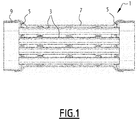
- Motor vehicle exhaust systems may include heat exchangers of the type shown on the figure 1 .
- a heat exchanger 1 comprises a plurality of tubes 3 for circulating the exhaust gases. These tubes are held at each of their longitudinal ends by a grid 5.
- a casing 7 is placed around the tubes 3 and grids 5.
- the tubes 3, the grids 5 and the casing 7 are fixed to each other by brazing, in an oven.
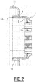
- Each grid 5 has an upstanding edge 9 facing outwardly of the heat exchanger, for attachment to a body 11, shown in FIG. figure 2 .
- the body 11 is for example integrated with a three-way valve for selectively directing the exhaust gas either to the heat exchanger or to a bypass duct of the heat exchanger.
- the extreme edge 13 of the upstanding edge 9 must be sufficiently far away from the junction between the grid 5 and the casing 7 so as not to melt the solder material solidarizing the grid 5 to the casing 7, during the welding of the grid 5 on the body 11.
- the grid 5 has a generally rectangular shape. It can be formed from a flat sheet, the sides of which are folded so as to give it a bowl shape, and thus create the erected edge 9. The sheet is then pierced, so as to create the receiving orifices of the tubes 3.
- the material When shaping the flat sheet, the material is compressed at each corner of the erected edge 9.
- the surface condition inside the four corners is not good. There are wrinkles both inside and outside the bowl.
- the shaping of the grid does not allow to have a good surface condition, nor good dimensional tolerances, in each corner of the erect edge 9.
- the heat exchanger 1 can be fixed to a barrel stretching formed in the body 11.
- the erected edge 9 is inserted inside the barrel 15.
- the edges of the barrel drawing 15 are absolutely not planar, due to the elastic return of the material during forming.
- the edges of the barrel stretch are not not perpendicular to the plane of the opening defined in the body 11, the draft angle being of the order of 2 °.
- the clearance between the upstanding edge 9 of the grid and the barrel stretching 15 is not constant, and may be greater than 0.5 mm on average.
- MAG Metal Active Gas
- the length of the erect edge 9 is limited by the fact that the compression of the material in the corners becomes impossible beyond a certain limit.
- the barrel stretch has a maximum length, related to the maximum allowable elongation of the material.
- the MAG process has known defects, the most important of which is to deform the parts to be welded, because these parts are heated at high temperature, and locally.
- the invention aims to provide a heat recovery device that does not have the above defects.
- the grid is turned in the opposite direction of the figure 1 .
- This allows the connection between the body and the grid at the level of the plane surface of the grid surrounding the receiving holes of the tubes. It is therefore no longer necessary to perform a canon stretching around the opening of the body, the connection between the body and the gate being made at two flat surfaces, parallel to one another.
- the height of the erected edge is less important than on the figures 1 and 2 because it is not necessary to extend it to the level of the free edge of the barrel stretching. It is only necessary to join the housing of the heat exchanger. The manufacture of the grid is easier, and the deformations less pronounced.
- the heat recovery device 17 is intended to be integrated in an exhaust line, typically an exhaust line of a vehicle equipped with a heat engine.
- the vehicle is for example a motor vehicle, typically a car or a truck.
- the heat recovery device 17 is provided to recover a portion of the heat energy of the exhaust gas flowing in the exhaust line.
- the heat energy thus recovered is used in the vehicle, for example to accelerate the rise in temperature of the engine, or to ensure the heating of the passenger compartment.
- the heat recovery device 17 shown on the Figures 3 to 5 includes a body 19 ( figure 5 ) internally delimiting a passage 21 for circulation of the exhaust gas, and a heat exchanger 23.
- the body 19 has an opening 25 through which the circulation passage 21 communicates with the heat exchanger 23.
- the body 19 is for example a valve body.
- the valve is typically a three-way valve, the body 19 having at least one inlet for the exhaust gas and two outlets, all communicating fluidly with the circulation passage 21.
- the inlet is in fluid communication with the collector collecting the exhaust gas at the outlet of the combustion chambers of the engine.
- One of the outlets constitutes the opening 25 and communicates with the exhaust gas flow side of the heat exchanger 23.
- the other outlet opens into a bypass duct of the heat exchanger. On the figure 5 only the opening 25 has been shown.
- the body 19 is an exhaust gas circulation duct, the heat exchanger being mounted as a bypass on this duct.
- the heat exchanger 23 comprises a housing 27, and a plurality of exhaust gas circulation tubes 29, extending inside the housing 27.
- the tubes 29 communicate fluidly with the circulation passage 21 through the opening 25.
- the casing 27 has a proximal edge 31 delimiting a proximal opening 33.
- the proximal edge 31 and the distal edge 35 are closed contours.
- the heat exchanger 23 also comprises at least one grid 39 disposed in the proximal opening 33.
- the grid 39 comprises a wall 41 in which orifices 43 are formed.
- Each tube 29 has a proximal end 45, engaged in one of the orifices 43 and fixed to the grid 39.
- the heat exchanger 23 comprises another gate 47 disposed in the distal opening 37.
- the other gate 47 comprises a wall 49 in which orifices 51 are formed.
- Each tube 29 has a distal end 53 engaged in one of the orifices 51 and fixed to the other grid 47.
- the grid 39 and the other gate 47 are identical in all respects. Only the grid 39 will therefore be described below in detail.
- the tubes 29 are rectilinear, and extend longitudinally from the proximal end 45 to the distal end 53.
- Each tube 29 thus has two large faces 55, 57, opposite to one another, and connected to one another by slices 59.
- the large faces 55, 57 extend substantially in planes containing the longitudinal directions L and transverse T. These planes are perpendicular to a direction of elevation E, materialized on the figure 3 .
- the tubes 29 are all stacked in the direction of elevation.
- the heat exchanger 23 in a transverse plane comprises at most a single tube.
- Each tube 29 thus extends substantially over the entire transverse width of the heat exchanger 23.
- the tubes 29 are stacked so that the large face 55 of a given tube is placed opposite the large face 57 of the tube immediately below in the stack in the direction of elevation.
- the fins 61 are placed inside each tube 29, so as to promote heat exchange gas side.
- the fins 61 are for example made in the form of an accordion-folded metal foil and introduced inside the tube 29.
- the orifices 43 and 51 of the grids 39 and 47 have a shape conjugate with that of the tubes 29. They are therefore of elongated shape transversely and extend substantially over the entire width of the grid. They are arranged in a single column.
- the grid 39 comprises an upstanding edge 60, extending around the wall 41 and projecting from the wall 41 towards the inside of the heat exchanger 23.
- the wall 41 is substantially rectangular, with rounded corners. Consequently, the erected edge 60 comprises two sections 61 substantially parallel to each other extending in the transverse direction T, and two sections 63 substantially parallel to each other extending in the direction of E.
- the two sections 61 are parallel to each other and extend in the transverse direction T.
- the two sections 63 are parallel to each other and extend according to the elevation direction E.
- the sections 61 and 63 are connected to each other by curved portions.
- the erected edge 60 projects in the longitudinal direction L. As visible on the figure 4 it is engaged within the proximal edge 31 of the housing 27, the proximal edge 31 being pressed against an outer surface of the upstanding edge 60.
- the upstanding edge 60 is rigidly fixed to the housing 27. More specifically, the proximal edge 31 is brazed on the erect edge 60.
- the wall 41 of the grid 39 is offset outside the housing 27. It is offset along the longitudinal direction L. By this it is meant that it is not located inside the housing 27, but is located longitudinally beyond the proximal end 31 of the housing 27.
- the wall 41 of the grid 39 has around the orifices 43 a flat surface 65 facing the body 19.
- the flat surface 65 extends in a certain plane. This plane is perpendicular to the longitudinal direction L and therefore contains the transverse direction T and the elevation direction E.
- the flat surface 65 extends all around the orifices 43.
- the flat surface 65 is therefore closed contour.
- This width is taken in a direction perpendicular to the line 67 of junction between the erected edge 60 and the wall 41. In other words, this width is taken in the direction of elevation E along the section 61 of the erected edge 60, and in the transverse direction T along the section 63 of the edge trained 60.
- the flat surface 65 extends in the example shown to the junction line 67 between the upright edge 60 and the wall 41, that is to say to the outer edge of the wall 41.
- the opening 25 is cut in a wall of the body 19.
- This flat zone 68 delimits on one side the inside of the circulation passage 21, and is therefore directly in contact with the exhaust gas. At the opposite, it is in contact with the grid 39 of the heat exchanger.
- the opening 25 of the body 19 is delimited by a flat edge 69, pressed against the flat surface 65.
- the flat edge 69 is therefore on one side in contact with the flat surface 65, and opposite the flat surface 65, with the exhaust gas circulating in the body 19.
- the flat surface 65 and the flat edge 69 are rigidly attached to each other in an exhaust gas-tight manner.
- the flat surface 65 and the flat edge 69 are directly attached to each other.
- the flat zone 68 bears no relief around the flat edge 69, so as to allow the position of the grid 39 to be adjusted relative to the body 19.
- the other grid 47 is also mounted on a flat area, so that it is possible to adjust the positions of the two ends of the heat exchanger relative to each other.
- the flat edge 69 has towards the heat exchanger 23 a flat outer surface 71, pressed against the flat surface 65.
- This flat outer surface 71 extends in a plane, this plane being perpendicular to the longitudinal direction L in the example shown.
- the edge 69 has a closed contour and extends all the way around the opening 25.
- the opening 25 is of such size and shape that all the orifices 43 are located at the right of said opening 25.
- the proximal ends 45 of the tubes 29 project beyond the grid 39, and penetrate slightly inside the opening. the opening 25, as illustrated on the figure 5 .
- the heat exchanger 23 further comprises a reinforcing grid 73, arranged to reinforce the connection between the tubes 29 and the grid 39. It advantageously comprises another reinforcing grid 75, arranged to reinforce the connection between the tubes 29 and the Another gate 47.
- the gate 73 and the gate 75 are identical, only the gate 73 is thus described below.
- the reinforcing grid 73 is a plate in which lights 77 have been formed.
- the lights 77 are delimited by passes 79 ( figure 5 ) and are each traversed by the proximal end 45 of one of the tubes 29.
- the lights 77 are placed facing each of one of the orifices 43.
- the necks 79 are brazed on the tubes 29.
- the peripheral edge 81 of the reinforcing plate, and the fields 83 located between the lights 77, are brazed on the inner surface of the wall 41.
- proximal edge 31 and the distal edge 35 of the housing 27 are located at the two opposite longitudinal ends thereof.
- the casing 27 is made of two half-shells 85, 87.
- the half-shells 85, 87 are joined to each other by brazing, along two longitudinal lines 89 (FIG. figure 6 ).
- Each half-shell 85, 87 has a U-section in a plane perpendicular to the longitudinal direction L.
- the casing 27 has a central tubular portion 91 having a first straight section, the proximal opening 33 having a second section greater than the first section ( figure 4 ). Similarly, the distal opening 37 has a section greater than the first section, and typically equal to the second section.
- the proximal edge 31 of the casing 27 is connected to the central tubular portion 91 by a tubular section 93 which flares out from the central tubular portion 91.
- the distal edge 35 of the casing 27 is connected to the central tubular portion 91 by another tubular portion 95 which flares out from the central tubular portion 91.
- the tubular section 93 delimits a heat transfer fluid circulation channel 97 along the gate 39.
- the tubular section 95 delimits a heat transfer fluid circulation channel 98 in contact with the other gate 47.
- the passage section offered to the coolant by the circulation channel 97, and also by the channel 98, is significantly higher than in the heat exchanger shown in FIG. figure 1 .
- the flat surface 65 of the wall 41 is much wider in the invention than in the heat exchanger of the figure 1 . Indeed, this flat surface 65 is voluntarily enlarged in the invention, to allow a good quality waterproof fastening of the flat edge 69 on the flat surface 65.
- the wall 41 is in the invention deported outside the housing 27.
- the wall in which are formed the tube receiving orifices is placed inside the housing 7.
- This large passage section 97 is particularly advantageous, since it is thus possible to increase the flow of heat transfer fluid in contact with the grid 39.
- the gate 39 is typically located at the entrance of the exhaust gas inside. of the heat exchanger.
- the heat exchangers used in the exhaust lines must never boil. The most critical boiling point is always located on the exhaust gas inlet side, ie in the zone where the exhaust gases are the hottest. In case of boiling, the heat transfer fluid is transformed into vapor, so that the heat exchange at the inlet of the heat exchanger is locally gas-gas.
- the skin temperature of the exchanger increases rapidly, and can approach the temperature of the exhaust gas (of the order of 850 ° C for example). This may locally create a thermal shock and thermal gradients causing breaks, and therefore leaks, at the solder solidarisant the various components of the heat exchanger to each other.
- the casing 27 has a heat-transfer fluid inlet 99 and a heat-transfer fluid outlet 101 ( figures 3 and 6 ).
- the inlet 99 and the heat transfer fluid outlet 101 are formed in the half-shell 87.
- the inlet 99 and the heat transfer fluid outlet 101 are arranged side by side, and offset longitudinally, one by report to the other.
- the inlet 99 is located on the side of the gate 39, and the outlet 101 on the side of the gate 47.
- the coolant inlet 99 is located towards the exhaust gas inlet and the 101 output of heat transfer fluid to the exhaust gas outlet.
- the coolant inlet 99 is located in the central tubular portion 91 of the housing 27.
- the central tubular part 91 has a zone 103 projecting outwardly of the housing 27, extending from the inlet 99 of heat transfer fluid to the heat transfer fluid circulation channel 97, along the gate 39.
- Area 103 is not represented on the Figures 3 to 5 .
- the casing 27 has two large faces 105 and 107, substantially perpendicular to the elevation direction E, and two lateral faces 109, substantially perpendicular to the transverse direction T, and connecting the faces 105 and 107 to each other. 'other.
- the inlet 99 of coolant, and typically the heat transfer fluid outlet 101, are formed in one of the lateral faces 109.
- the projecting zone 103 is advantageously formed on the large surface 107. It has a generally triangular shape, such as visible on the figure 7 . It extends transversely from the inlet 99 of heat transfer fluid to the side face 109 opposite the inlet 99 of heat transfer fluid. Its width, taken in the longitudinal direction, decreases from the inlet 99 of heat transfer fluid to the side face 109 opposite the inlet 99 of heat transfer fluid.
- the protruding zone 103 protrudes with respect to a central zone 111 of the central tubular portion 91 over a height substantially equal to that of the proximal end 31.
- the protruding zone 103 makes it possible to collect the coolant at the inlet 99 of heat transfer fluid, and to direct it preferentially towards the circulation channel 97. This promotes cooling at the inlet of the heat exchanger and limits the risk of boiling.
- the casing 27 also comprises another projecting zone 112, extending from the heat transfer fluid outlet 101 to the heat transfer fluid circulation channel 98 along the other gate 47 (FIG. figure 7 ).
- the projecting zone 112 is symmetrical with the protruding zone 103 with respect to the median plane of the heat exchanger perpendicular to the longitudinal direction L.
- the tubes 29 have protuberances 113 forming spacers maintaining a determined spacing between the tubes 29, and between the tubes 29 and the housing 27. These protuberances 113 are distributed over the large faces 55 and 57 of the tubes.
- each of the large faces 55, 57 carries about ten protuberances 113.
- the protuberances 113 project outwardly from the tubes 29. They are obtained by deformation of the metal constituting the tube 29.
- the protuberances 113 in contact with the housing 27 are all located outside the heat transfer fluid circulation channel 97 along the gate 39, and typically also outside the heat transfer fluid circulation channel 98 along the other gate 47. .
- these protuberances are also located outside the projecting zone 103 and outside the projecting zone 112.
- the protuberances 113 formed on the large face 55 of a tube 29 are located vis-a-vis the protuberances 113 formed on the large face 57 of the same tube 29.
- vis-à-vis we opposite to each other in the direction of elevation E.
- the protuberances 113 formed on a given tube 29 are located in the extension of the protuberances 113 of the other tubes 29 in the direction of elevation E, as illustrated on the figure 4 .
- all the tubes 29 have protuberances 113 having the same arrangement on their two opposite large faces 55, 57, such that these protuberances 113 form column stacks, in the direction of elevation E. is favorable for increasing the rigidity of the heat exchanger 23.
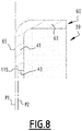
- the flat surface 65 of the grid 39 extends in a first plane P1, the orifices 43 being surrounded by a rim 115 adjoining the flat surface 65, the rim 115 extending in a second plane P2 parallel to the first plane P1 and shifted inwardly of the heat exchanger 23 relative to the first plane P1. This is illustrated on the figure 8 .
- the flange 115 extends over the entire periphery of the orifices 43. It is closed contour, and is adjacent to the flat surface 65. It is separated from the flat surface 65 by a step.
- the brazing material can not spread on the flat surface 65. It is retained by the step separating the rim 115 from the flat surface 65.
- the invention according to another aspect relates to the method of manufacturing the heat recovery device 17 described above.
- the other grid 47 is soldered to the casing 27 and to the tubes 29.
- reinforcing grids 73, 75 are advantageously assembled by soldering to the tubes 29 and the grids 39, 47, at the same step.
- the assembly step also makes it possible to secure the half-shells 85, 87 of the casing 27 to one another.
- the housing 27 is assembled to the grid 39 by brazing the proximal edge 31 on the upright edge 60.
- the tubes 29 are joined to each other by brazing, this brazing being preferably carried out at the level of the protuberances 113.
- the tubes 29 are assembled to the housing 27 by brazing the protuberances 113 on the housing 27, and more precisely on the central tubular portion 91 of the housing 27.
- the brazing step is advantageously carried out in an oven.
- this weld is made by transparency, through the flat edge 69.
- the weld line is closed contour, and extends around the entire periphery of the opening 25.
- solder paste is deposited between the flat edge 69 and the flat surface 65.
- the solder paste is melted, for example by placing the body 19 and the heat exchanger 23 in an oven.
- the brazing of the flat surface 65 and the flat edge 69 can be performed at the same time as the soldering of the different elements of the heat exchanger to each other.
- the heat recovery device 17, and the corresponding manufacturing method may have multiple variants.
- the gate 47 disposed in the distal opening 37 of the housing 27 could be of a different type from that arranged in the proximal opening 33.
- the tubes 29 do not necessarily have the form described above. They could be of circular section, or oval, or any other adapted section. These tubes are not necessarily rectilinear, but in a variant are curved. In this case, the distal opening 37 of the casing 27 is not necessarily placed longitudinally opposite the proximal opening 33.
- the heat transfer fluid is typically a liquid. Alternatively, it is another type of fluid.
- the heat exchanger 23 is not necessarily symmetrical with respect to a median transverse plane of the heat exchanger. It may not include a channel 98 for circulating the coolant in contact with the other grid 47 and / or have no protruding zone 112.
- the wall 41 of the grid 39 can have all kinds of shapes. It is not necessarily rectangular. Alternatively, the wall 41 is circular, or elliptical, or has any other suitable form.
- the opening 25 formed in the body 19 does not have a rectangular shape either. It typically has a shape corresponding to the shape of the grid 39, and more particularly to the shape of the wall 41.
- the upright edge 60 is not necessarily engaged within the proximal edge 31 of the housing 27. In a variant, it is the proximal edge 31 of the housing 27 which is engaged in the upright edge 60 of the grid 39.
- the casing 27 does not necessarily consist of two half-shells 85, 87 assembled to one another. It could be obtained by rolling a sheet around a longitudinal axis, or by deformation of a pipe section.
- the tubes 29 can be arranged in a variety of different ways inside the heat exchanger 23. In particular, it is possible to place several tubes 29 next to one another transversely and not just one as described above. .
- the flat surface 65 does not necessarily extend in a single plane. It may comprise several planar zones, arranged in several planes parallel to each other or inclined relative to each other. In these cases, the flat edge 69 has substantially the same shape as the flat surface 65. In any case, the flat edge 69 and the flat surface 65 are in contact with one another on a closed contour area surrounding the opening 25 and surrounding all the orifices 43, 51. This zone is sufficiently wide to allow the attachment of the flat surface 65 and the flat edge 69 to each other, preferably by laser welding or brazing.
Abstract
Le dispositif de récupération de chaleur comprend un corps (19) délimitant intérieurement un passage (21) de circulation des gaz d'échappement, et un échangeur de chaleur (23), l'échangeur de chaleur (23) comprend :- un carter (27);- une pluralité de tubes (29) de circulation des gaz d'échappement;- au moins une grille (39) disposée dans l'ouverture proximale (33) du carter, la grille (39) comprenant une paroi (41) dans laquelle sont ménagés des orifices (43) de réception des tubes (29), la grille (39) ayant en outre un bord dressé (60) faisant saillie vers l'intérieur de l'échangeur de chaleur (23), le bord dressé (60) étant rigidement fixé au carter (27) ;- la paroi (41) de la grille (39) présentant autour des orifices (43) une surface plane (65) tournée vers le corps (19) ;- le corps (19) ayant une ouverture (25) délimitée par un bord plat (69) plaqué contre la surface plane (65) ;- la surface plane (65) et le bord plat (69) étant rigidement fixés l'un à l'autre de manière étanche aux gaz d'échappement.The heat recovery device comprises a body (19) internally defining an exhaust gas circulation passage (21), and a heat exchanger (23), the heat exchanger (23) comprises: - a housing ( 27); - a plurality of exhaust gas circulation tubes (29); - at least one gate (39) disposed in the proximal opening (33) of the casing, the gate (39) comprising a wall (41); in which tube receiving orifices (43) are provided, the grid (39) further having an upstanding edge (60) projecting inwardly of the heat exchanger (23), the erected edge (60) being rigidly fixed to the housing (27) - the wall (41) of the grid (39) having around the orifices (43) a flat surface (65) facing the body (19) - the body (19) ) having an opening (25) delimited by a flat edge (69) pressed against the flat surface (65) - the flat surface (65) and the flat edge (69) being rigidly fixed to each other other in an exhaust gas-tight manner.
Description
L'invention concerne en général les dispositifs de récupération de chaleur pour lignes d'échappement.The invention generally relates to heat recovery devices for exhaust lines.
Les lignes d'échappement de véhicules automobiles peuvent comporter des échangeurs de chaleur du type représenté sur la
Chaque grille 5 comporte un bord dressé 9 orienté vers l'extérieur de l'échangeur de chaleur, pour fixation sur un corps 11, représenté sur la
La grille 5 a une forme générale rectangulaire. Elle peut être formée à partir d'une tôle plate, dont on rabat les côtés de manière à lui conférer une forme de cuvette, et ainsi créer le bord dressé 9. La tôle est ensuite percée, de manière à créer des orifices de réception des tubes 3.The
Lors de la mise en forme de la tôle plate, la matière est comprimée à chaque angle du bord dressé 9. L'état de surface à l'intérieur des quatre angles n'est pas bon. On constate des plis aussi bien à l'intérieur qu'à l'extérieur de la cuvette.When shaping the flat sheet, the material is compressed at each corner of the
Ainsi, la mise en forme de la grille ne permet pas d'avoir un bon état de surface, ni de bonnes tolérances dimensionnelles, dans chaque angle du bord dressé 9.Thus, the shaping of the grid does not allow to have a good surface condition, nor good dimensional tolerances, in each corner of the
De plus, il est difficile d'obtenir une bonne planéité de chacun des côtés du bord dressé 9. Ceci est dû au retour élastique de la matière, aux quatre angles.In addition, it is difficult to obtain a good flatness of each side of the
Par ailleurs, comme visible sur la
Bien que l'étirage canon soit obtenu par un allongement de la matière et non par une compression, les bords de l'étirage canon 15 ne sont absolument pas plans, du fait du retour élastique de la matière lors du formage. Les bords de l'étirage canon ne sont pas perpendiculaires au plan de l'ouverture délimitée dans le corps 11, l'angle de dépouille étant de l'ordre de 2°.Although the barrel stretching is obtained by elongation of the material and not by compression, the edges of the
Ainsi, le jeu entre le bord dressé 9 de la grille et l'étirage canon 15 n'est pas constant, et peut être supérieur à 0,5 mm en moyenne.Thus, the clearance between the
Il est envisageable de souder le bord dressé 9 et l'étirage canon 15 en bout, dans la configuration représentée sur la
Dans le domaine de l'échappement, le procédé de soudage utilisé traditionnellement est le MAG (Metal Active Gas). Avec un tel procédé de soudage, le jeu important entre le bord dressé et l'étirage canon peut générer des défauts, voire même des trous.In the field of exhaust, the welding process traditionally used is MAG (Metal Active Gas). With such a welding process, the large clearance between the erected edge and the barrel stretch can generate defects, or even holes.
Pour souder à clin, il serait nécessaire de faire dépasser l'un de l'autre le bord dressé 9 et l'étirage canon 15. Or, la longueur du bord dressé 9 est limitée du fait que la compression de la matière dans les angles devient impossible au-delà d'une certaine limite.To weld clapboard, it would be necessary to exceed the one of the other
De même, l'étirage canon présente une longueur maximale, liée à l'allongement admissible maximum de la matière.Similarly, the barrel stretch has a maximum length, related to the maximum allowable elongation of the material.
Par ailleurs, le procédé MAG présente des défauts connus, dont le plus important est de déformer les pièces à souder, du fait que ces pièces sont chauffées à haute température, et de manière locale.Furthermore, the MAG process has known defects, the most important of which is to deform the parts to be welded, because these parts are heated at high temperature, and locally.
Ce défaut est particulièrement critique quand l'échangeur de chaleur 1 doit être rigidement fixé à un corps de vanne, qui doit avoir une bonne géométrie finale pour que l'axe du volet puisse tourner sans interférence avec le corps de vanne, et pour que la vanne présente un bon niveau d'étanchéité.This defect is particularly critical when the heat exchanger 1 must be rigidly attached to a valve body, which must have a good final geometry so that the axis of the flap can rotate without interference with the valve body, and that the valve has a good level of tightness.
Dans ce contexte, l'invention vise à proposer un dispositif de récupération de chaleur qui ne présente pas les défauts ci-dessus.In this context, the invention aims to provide a heat recovery device that does not have the above defects.
A cette fin, l'invention porte sur un dispositif de récupération de chaleur pour une ligne d'échappement, le dispositif comprenant un corps délimitant intérieurement un passage de circulation des gaz d'échappement, et un échangeur de chaleur, l'échangeur de chaleur comprenant :
- un carter ayant un bord proximal délimitant une ouverture proximale ;
- une pluralité de tubes de circulation des gaz d'échappement, s'étendant à l'intérieur du carter ;
- au moins une grille disposée dans l'ouverture proximale, la grille comprenant une paroi dans laquelle sont ménagés des orifices, chaque tube ayant une extrémité proximale engagée dans un des orifices et fixée à la grille, la grille ayant en outre un bord dressé s'étendant autour de la paroi et faisant saillie à partir de la paroi vers l'intérieur de l'échangeur de chaleur, le bord dressé étant rigidement fixé au carter ;
- la paroi de la grille présentant autour des orifices une surface plane tournée vers le corps ;
- le corps ayant une ouverture délimitée par un bord plat plaqué contre la surface plane ;
- la surface plane et le bord plat étant rigidement fixés l'un à l'autre de manière étanche aux gaz d'échappement.
- a housing having a proximal edge defining a proximal opening;
- a plurality of exhaust gas tubes extending into the housing;
- at least one gate disposed in the proximal opening, the gate comprising a wall in which orifices are formed, each tube having a proximal end engaged in one of the orifices and fixed to the gate, the gate having in addition an erected edge extending around the wall and protruding from the wall towards the inside of the heat exchanger, the erected edge being rigidly fixed to the housing;
- the wall of the grid having around the orifices a flat surface facing the body;
- the body having an opening defined by a flat edge pressed against the flat surface;
- the flat surface and the flat edge being rigidly fixed to each other in an exhaust gas-tight manner.
Ainsi, dans l'invention, la grille est tournée en sens inverse de la
Ceci permet avantageusement de solidariser la grille et le corps par soit un procédé de brasage, soit un procédé de soudure laser.This advantageously allows to secure the grid and the body by either a brazing process or a laser welding process.
Ces procédés sont avantageux, car ils n'imposent pas de chauffer de manière considérable les pièces, et minimisent donc le risque de déformation du corps.These methods are advantageous because they do not require considerable heating of the parts, and thus minimize the risk of deformation of the body.
Obtenir une bonne planéité de la surface plane de la grille et du bord plat du corps est plus aisé que contrôler la géométrie de l'étirage canon ou du bord dressé sur le dispositif des
Par ailleurs, la hauteur du bord dressé est moins importante que sur les
Le dispositif de récupération de chaleur peut également présenter une ou plusieurs des caractéristiques ci-dessous, considérées individuellement ou selon toutes les combinaisons techniquement possibles :
- la surface plane et le bord plat sont rigidement fixés l'un à l'autre par une soudure laser ou par brasage ;
- le bord dressé de la grille est rigidement fixé au bord proximal du carter, la paroi de la grille étant déportée à l'extérieur du carter ;
- la surface plane est à contour fermé et présente une largeur d'au moins deux millimètres ;
- le carter comporte une partie tubulaire centrale ayant une première section droite, l'ouverture proximale ayant une seconde section supérieure à la première section ;
- le bord proximal du carter est raccordé à la partie tubulaire centrale par un tronçon tubulaire qui s'évase à partir de la partie tubulaire centrale, le tronçon tubulaire délimitant un canal de circulation de fluide caloporteur le long de la grille ;
- le carter présente une entrée de fluide caloporteur et une sortie de fluide caloporteur, l'entrée de fluide caloporteur étant ménagée dans la partie tubulaire centrale, la partie tubulaire centrale ayant une zone en saillie vers l'extérieur du carter s'étendant depuis l'entrée de fluide caloporteur jusqu'au canal de circulation de fluide caloporteur le long de la grille ;
- les tubes présentent des protubérances formant des entretoises maintenant un écartement déterminé entre les tubes, et entre les tubes et le carter, les protubérances en contact avec le carter étant toutes situées en dehors du canal de circulation de fluide caloporteur le long de la grille ;
- la surface plane s'étend dans un premier plan, les orifices étant entourés par un rebord jouxtant la surface plane, le rebord s'étendant dans un second plan parallèle au premier plan et décalé vers l'intérieur de l'échangeur de chaleur par rapport au premier plan.
- the flat surface and the flat edge are rigidly fixed to each other by laser welding or brazing;
- the erected edge of the grid is rigidly fixed to the proximal edge of the casing, the wall of the gate being offset to the outside of the casing;
- the flat surface is of closed contour and has a width of at least two millimeters;
- the housing has a central tubular portion having a first cross section, the proximal opening having a second section greater than the first section;
- the proximal edge of the casing is connected to the central tubular portion by a tubular section which is flared from the central tubular portion, the tubular section delimiting a coolant circulation channel along the gate;
- the casing has a coolant inlet and a heat transfer fluid outlet, the coolant inlet being provided in the central tubular portion, the central tubular portion having an outwardly projecting zone of the casing extending from the heat transfer fluid inlet to the coolant circulation channel along the grid;
- the tubes have protrusions forming spacers maintaining a determined spacing between the tubes, and between the tubes and the housing, the protuberances in contact with the housing being all located outside the heat transfer fluid circulation channel along the gate;
- the flat surface extends in a first plane, the orifices being surrounded by a flange adjacent to the flat surface, the flange extending in a second plane parallel to the first plane and inwardly offset from the heat exchanger relative to in the foreground.
Selon un second aspect, l'invention porte sur un procédé de fabrication d'un dispositif ayant les caractéristiques ci-dessus,
- assembler par brasage le carter, les tubes et la grille les uns aux autres ;
- fixer la surface plane de la grille et le bord plat du corps l'un à l'autre par soudure laser ou par brasage.
- brazing the housing, the tubes and the grid together;
- fix the flat surface of the grid and the flat edge of the body to each other by laser welding or brazing.
D'autres caractéristiques et avantages de l'invention ressortiront de la description détaillée qui en est donnée ci-dessous, à titre indicatif et nullement limitatif, parmi lesquels :
- la
figure 1 est une vue en coupe d'un échangeur de chaleur non conforme à l'invention ; - la
figure 2 est une vue en coupe d'une extrémité de l'échangeur de chaleur de lafigure 1 , rapportée sur un corps ; - la
figure 3 est une vue éclatée d'un échangeur de chaleur d'un dispositif de récupération de chaleur selon l'invention ; - la
figure 4 est une vue en coupe longitudinale de l'échangeur de chaleur de lafigure 3 , à l'état assemblé ; - la
figure 5 est une vue en coupe d'une extrémité de l'échangeur de chaleur desfigures 3 et4 , rapportée sur un corps ; - la
figure 6 est une vue en perspective de l'échangeur de chaleur desfigures 3 à 5 ; - la
figure 7 est une vue de dessous de l'échangeur de chaleur, pour une variante de réalisation ; - la
figure 8 est une vue agrandie en coupe, d'une partie d'une des grilles de l'échangeur de chaleur desfigures 3 et4 ; et - la
figure 9 est une vue en perspective de la grille de lafigure 8 .
- the
figure 1 is a sectional view of a heat exchanger not according to the invention; - the
figure 2 is a sectional view of one end of the heat exchanger of thefigure 1 , reported on a body; - the
figure 3 is an exploded view of a heat exchanger of a heat recovery device according to the invention; - the
figure 4 is a longitudinal sectional view of the heat exchanger of thefigure 3 , in the assembled state; - the
figure 5 is a sectional view of one end of the heat exchanger offigures 3 and4 , reported on a body; - the
figure 6 is a perspective view of the heat exchanger of theFigures 3 to 5 ; - the
figure 7 is a bottom view of the heat exchanger for an alternative embodiment; - the
figure 8 is an enlarged sectional view of a portion of one of the grids of the heat exchanger offigures 3 and4 ; and - the
figure 9 is a perspective view of the grid of thefigure 8 .
Le dispositif de récupération de chaleur 17 est prévu pour être intégré dans une ligne d'échappement, typiquement une ligne d'échappement d'un véhicule équipé d'un moteur thermique. Le véhicule est par exemple un véhicule automobile, typiquement une voiture ou un camion.The
Le dispositif de récupération de chaleur 17 est prévu pour récupérer une partie de l'énergie calorifique des gaz d'échappement circulant dans la ligne d'échappement. L'énergie calorifique ainsi récupérée est utilisée à bord du véhicule, par exemple pour accélérer la montée en température du moteur thermique, ou pour assurer le chauffage de l'habitacle.The
Le dispositif de récupération de chaleur 17 représenté sur les
Le corps 19 présente une ouverture 25, par laquelle le passage de circulation 21 communique avec l'échangeur de chaleur 23.The
Le corps 19 est par exemple un corps de vanne. Dans ce cas, la vanne est typiquement une vanne trois voies, le corps 19 présentant au moins une entrée pour les gaz d'échappement et deux sorties, communiquant toutes fluidiquement avec le passage de circulation 21. L'entrée est en communication fluidique avec le collecteur captant les gaz d'échappement à la sortie des chambres de combustion du moteur thermique. L'une des sorties constitue l'ouverture 25 et communique avec le côté de circulation des gaz d'échappement de l'échangeur de chaleur 23. L'autre sortie débouche dans un conduit de by-pass de l'échangeur de chaleur. Sur la
En variante, le corps 19 est un conduit de circulation des gaz d'échappement, l'échangeur de chaleur étant monté en dérivation sur ce conduit.In a variant, the
Comme illustré sur les
Les tubes 29 communiquent fluidiquement avec le passage de circulation 21 à travers l'ouverture 25.The
Le carter 27 présente un bord proximal 31, délimitant une ouverture proximale 33.The
Il comporte également un bord distal 35, délimitant une ouverture distale 37. Le bord proximal 31 et le bord distal 35 sont à contours fermés.It also has a
L'échangeur de chaleur 23 comporte également au moins une grille 39, disposée dans l'ouverture proximale 33. La grille 39 comprend une paroi 41 dans laquelle sont ménagés des orifices 43.The
Chaque tube 29 présente une extrémité proximale 45, engagée dans un des orifices 43 et fixée à la grille 39.Each
Avantageusement, l'échangeur de chaleur 23 comprend une autre grille 47 disposée dans l'ouverture distale 37. L'autre grille 47 comprend une paroi 49 dans laquelle sont ménagés des orifices 51. Chaque tube 29 présente une extrémité distale 53 engagée dans un des orifices 51 et fixée à l'autre grille 47.Advantageously, the
Typiquement, la grille 39 et l'autre grille 47 sont en tous points identiques. Seule la grille 39 sera donc décrite ci-dessous en détail.Typically, the
De préférence, les tubes 29 sont rectilignes, et s'étendent longitudinalement depuis l'extrémité proximale 45 jusqu'à l'extrémité distale 53.Preferably, the
Par exemple, ils présentent dans un plan transversal perpendiculaire à la direction longitudinale une section sensiblement rectangulaire, constante sur toute la longueur longitudinale du tube 29. La section est allongée suivant une direction transversale T. Les directions longitudinale L et transversale T sont représentées sur la
Chaque tube 29 présente donc deux grandes faces 55, 57, opposées l'une à l'autre, et raccordées l'une à l'autre par des tranches 59. Les grandes faces 55, 57 s'étendent sensiblement dans des plans contenant les directions longitudinale L et transversale T. Ces plans sont perpendiculaires à une direction d'élévation E, matérialisée sur la
Avantageusement, les tubes 29 sont tous empilés suivant la direction d'élévation. En d'autres termes, l'échangeur de chaleur 23 dans un plan transversal comprend au plus un seul tube.Advantageously, the
Chaque tube 29 s'étend donc pratiquement sur toute la largeur transversale de l'échangeur de chaleur 23. Les tubes 29 sont empilés de telle sorte que la grande face 55 d'un tube donné est placée en vis-à-vis de la grande face 57 du tube immédiatement en dessous dans l'empilement suivant la direction d'élévation.Each
Des ailettes 61 sont placées à l'intérieur de chaque tube 29, de manière à favoriser les échanges de chaleur côté gaz. Les ailettes 61 sont par exemple réalisées sous la forme d'une feuille métallique pliée en accordéon et introduites à l'intérieur du tube 29.The
Les orifices 43 et 51 des grilles 39 et 47 ont une forme conjuguée de celle des tubes 29. Ils sont donc de forme allongée transversalement et s'étendent pratiquement sur toute la largeur de la grille. Ils sont agencés en une colonne unique.The
La grille 39 comprend un bord dressé 60, s'étendant autour de la paroi 41 et faisant saillie à partir de la paroi 41 vers l'intérieur de l'échangeur de chaleur 23.The
Dans l'exemple représenté, la paroi 41 est sensiblement rectangulaire, avec des angles arrondis. En conséquence, le bord dressé 60 comporte deux tronçons 61 sensiblement parallèles l'un à l'autre s'étendant suivant la direction transversale T, et deux tronçons 63 sensiblement parallèles l'un à l'autre s'étendant suivant la direction d'élévation E. De préférence, les deux tronçons 61 sont parallèles l'un à l'autre et s'étendent suivant la direction transversale T. De préférence, les deux tronçons 63 sont parallèles l'un à l'autre et s'étendent suivant la direction d'élévation E. Les tronçons 61 et 63 sont raccordés les uns aux autres par des portions incurvées.In the example shown, the
Le bord dressé 60 fait saillie suivant la direction longitudinale L. Comme visible sur la
La paroi 41 de la grille 39 est déportée à l'extérieur du carter 27. Elle est déportée suivant la direction longitudinale L. On entend par là qu'elle n'est pas située à l'intérieur du carter 27, mais est située longitudinalement au-delà de l'extrémité proximale 31 du carter 27.The
La paroi 41 de la grille 39 présente autour des orifices 43 une surface plane 65 tournée vers le corps 19.The
Typiquement, la surface plane 65 s'étend dans un plan déterminé. Ce plan est perpendiculaire à la direction longitudinale L et contient donc la direction transversale T et la direction d'élévation E.Typically, the
La surface plane 65 s'étend tout autour des orifices 43. La surface plane 65 est donc à contour fermé.The
Elle présente une largeur d'au moins 2 mm, par exemple comprise entre 2 et 5 mm. Cette largeur est prise suivant une direction perpendiculaire à la ligne 67 de jonction entre le bord dressé 60 et la paroi 41. En d'autres termes, cette largeur est prise selon la direction d'élévation E le long du tronçon 61 du bord dressé 60, et suivant la direction transversale T le long du tronçon 63 du bord dressé 60.It has a width of at least 2 mm, for example between 2 and 5 mm. This width is taken in a direction perpendicular to the
La surface plane 65 s'étend dans l'exemple représenté jusqu'à la ligne de jonction 67 entre le bord dressé 60 et la paroi 41, c'est-à-dire jusqu'au bord extérieur de la paroi 41.The
L'ouverture 25 est découpée dans une paroi du corps 19.The
Typiquement, elle est découpée dans une zone 68 sensiblement plane de la paroi, de préférence avec une planéité inférieure à 0,3. Cette zone plane 68 délimite d'un côté l'intérieur du passage de circulation 21, et est donc directement en contact avec les gaz d'échappement. A l'opposée, elle est en contact avec la grille 39 de l'échangeur de chaleur.Typically, it is cut in a substantially
L'ouverture 25 du corps 19 est délimitée par un bord plat 69, plaqué contre la surface plane 65.The
Le bord plat 69 est donc d'un côté en contact avec la surface plane 65, et à l'opposé de la surface plane 65, avec les gaz d'échappement circulant dans le corps 19.The
La surface plane 65 et le bord plat 69 sont rigidement fixés l'un à l'autre de manière étanche aux gaz d'échappement.The
La surface plane 65 et le bord plat 69 sont directement fixés l'un à l'autre.The
Ils sont rigidement fixés l'un à l'autre par une soudure laser ou par brasage.They are rigidly fixed to each other by laser welding or brazing.
La zone plane 68 ne porte aucun relief autour du bord plat 69, de manière à permettre d'ajuster la position de la grille 39 par rapport au corps 19.The
Il est à noter que l'autre grille 47 est montée elle aussi sur une zone plane, de telle sorte qu'il est possible de régler les positions des deux extrémités de l'échangeur de chaleur l'une par rapport à l'autre.It should be noted that the
Le bord plat 69 présente vers l'échangeur de chaleur 23 une surface externe plane 71, plaquée contre la surface plane 65.The
Cette surface externe plane 71 s'étend dans un plan, ce plan étant perpendiculaire à la direction longitudinale L dans l'exemple représenté.This flat
Le bord 69 est à contour fermé et s'étend tout autour de l'ouverture 25.The
L'ouverture 25 est de taille et de forme telles que tous les orifices 43 sont situés au droit de ladite ouverture 25. Les extrémités proximales 45 des tubes 29 font saillie au-delà de la grille 39, et pénètrent légèrement à l'intérieur de l'ouverture 25, comme illustré sur la
L'échangeur de chaleur 23 comporte encore une grille de renfort 73, agencée pour renforcer la liaison entre les tubes 29 et la grille 39. Il comporte avantageusement une autre grille de renfort 75, agencée pour renforcer la liaison entre les tubes 29 et l'autre grille 47. La grille 73 et la grille 75 sont identiques, seule la grille 73 étant donc décrite ci-dessous.The
La grille de renfort 73 est une plaque dans laquelle des lumières 77 ont été ménagées. Les lumières 77 sont délimitées par des cols 79 (
Dans l'exemple représenté, le bord proximal 31 et le bord distal 35 du carter 27 sont situés aux deux extrémités longitudinales opposées de celui-ci.In the example shown, the
Le carter 27 est réalisé en deux demi-coquilles 85, 87. Les demi-coquilles 85, 87 sont solidarisées l'une à l'autre par brasage, le long de deux lignes longitudinales 89 (
Chaque demi-coquille 85, 87 présente une section en U dans un plan perpendiculaire à la direction longitudinale L.Each half-
Le carter 27 comporte une partie tubulaire centrale 91 ayant une première section droite, l'ouverture proximale 33 ayant une seconde section supérieure à la première section (
Pour ce faire, le bord proximal 31 du carter 27 est raccordé à la partie tubulaire centrale 91 par un tronçon tubulaire 93 qui s'évase à partir de la partie tubulaire centrale 91.To do this, the
De même, le bord distal 35 du carter 27 est raccordé à la partie tubulaire centrale 91 par un autre tronçon tubulaire 95 qui s'évase à partir de la partie tubulaire centrale 91.Similarly, the
Le tronçon tubulaire 93 délimite un canal 97 de circulation de fluide caloporteur le long de la grille 39. De la même façon, le tronçon tubulaire 95 délimite un canal 98 de circulation en fluide caloporteur au contact de l'autre grille 47.The
La section de passage offerte au fluide caloporteur par le canal de circulation 97, et également par le canal 98, est nettement plus élevée que dans l'échangeur de chaleur représenté sur la
Ceci résulte de plusieurs dispositions constructives de l'échangeur de chaleur.This results from several constructive arrangements of the heat exchanger.
Tout d'abord, la surface plane 65 de la paroi 41 est nettement plus large dans l'invention que dans l'échangeur de chaleur de la
Par ailleurs, comme souligné précédemment, la paroi 41 est dans l'invention déportée à l'extérieur du carter 27. Dans l'échangeur de chaleur de la
Cette grande section de passage 97 est particulièrement avantageuse, puisqu'il est ainsi possible d'augmenter le débit de fluide caloporteur au contact de la grille 39. La grille 39 est typiquement située à l'entrée des gaz d'échappement à l'intérieur de l'échangeur de chaleur. Or, les échangeurs de chaleur utilisés dans les lignes d'échappement ne doivent jamais entrer en ébullition. La zone la plus critique vis-à-vis de l'ébullition est toujours située du côté de l'entrée des gaz d'échappement, c'est-à-dire dans la zone où les gaz d'échappement sont les plus chauds. En cas d'ébullition, le fluide caloporteur se transforme en vapeur, de telle sorte que les échanges thermiques à l'entrée de l'échangeur de chaleur sont localement gaz-gaz. De ce fait, la température de peau de l'échangeur augmente rapidement, et peut s'approcher de la température des gaz d'échappement (de l'ordre de 850°C par exemple). Ceci risque de créer localement un choc thermique et des gradients thermiques provoquant des ruptures, et donc des fuites, au niveau des brasures solidarisant les différents composants de l'échangeur de chaleur les uns aux autres.This
Il est donc critique pour un échangeur de chaleur de ce type que le débit de fluide caloporteur au niveau de la grille 39 soit suffisamment élevé, pour empêcher tout risque d'ébullition.It is therefore critical for a heat exchanger of this type that the flow of heat transfer fluid at the
Le carter 27 présente une entrée de fluide caloporteur 99 et une sortie de fluide caloporteur 101 (
Dans l'exemple représenté, l'entrée 99 et la sortie 101 de fluide caloporteur sont ménagés dans la demi-coquille 87. L'entrée 99 et la sortie 101 de fluide caloporteur sont disposées côte à côte, et décalées longitudinalement l'une par rapport à l'autre. L'entrée 99 est située du côté de la grille 39, et la sortie 101 du côté de la grille 47. En d'autres termes, l'entrée 99 de fluide caloporteur est située vers l'entrée de gaz d'échappement et la sortie 101 de fluide caloporteur vers la sortie de gaz d'échappement.In the example shown, the
L'entrée 99 de fluide caloporteur est située dans la partie tubulaire centrale 91 du carter 27. Avantageusement, et comme illustré sur la
La zone 103 n'est pas représentée sur les
Plus précisément, le carter 27 présente deux grandes faces 105 et 107, sensiblement perpendiculaires à la direction d'élévation E, et deux faces latérales 109, sensiblement perpendiculaires à la direction transversale T, et raccordant les faces 105 et 107 l'une à l'autre. L'entrée 99 de fluide caloporteur, et typiquement la sortie 101 de fluide caloporteur, sont ménagées dans l'une des faces latérales 109. La zone en saillie 103 est ménagée avantageusement sur la grande face 107. Elle présente une forme générale triangulaire, comme visible sur la
Avantageusement, la zone en saillie 103 fait saillie par rapport à une zone centrale 111 de la partie tubulaire centrale 91 sur une hauteur sensiblement égale à celle de l'extrémité proximale 31.Advantageously, the protruding
La zone en saillie 103 permet de collecter le fluide caloporteur au niveau de l'entrée 99 de fluide caloporteur, et de le diriger préférentiellement vers le canal de circulation 97. Ceci favorise le refroidissement à l'entrée de l'échangeur de chaleur et limite le risque d'ébullition.The protruding
Avantageusement, le carter 27 comporte également une autre zone en saillie 112, s'étendant depuis la sortie de fluide caloporteur 101 jusqu'au canal 98 de circulation de fluide caloporteur le long de l'autre grille 47 (
La zone en saillie 112 est symétrique de la zone en saillie 103 par rapport au plan médian de l'échangeur de chaleur perpendiculaire à la direction longitudinale L.The projecting
Les tubes 29 présentent des protubérances 113 formant des entretoises maintenant un écartement déterminé entre les tubes 29, et entre les tubes 29 et le carter 27. Ces protubérances 113 sont réparties sur les grandes faces 55 et 57 des tubes.The
Dans l'exemple représenté, chacune des grandes faces 55, 57 porte une dizaine de protubérances 113.In the example shown, each of the large faces 55, 57 carries about ten
Les protubérances 113 font saillie vers l'extérieur des tubes 29. Elles sont obtenues par déformation du métal constituant le tube 29.The
Les protubérances 113 en contact avec le carter 27 sont toutes situées en dehors du canal 97 de circulation de fluide caloporteur le long de la grille 39, et typiquement également en dehors du canal 98 de circulation de fluide caloporteur le long de l'autre grille 47.The
Ceci est favorable pour la tenue mécanique entre le carter 27 et les protubérances 113.This is favorable for the mechanical strength between the
De préférence, ces protubérances sont également situées à l'extérieur de la zone en saillie 103 et à l'extérieur de la zone en saillie 112.Preferably, these protuberances are also located outside the projecting
Typiquement, les protubérances 113 formées sur la grande face 55 d'un tube 29 sont situées en vis-à-vis des protubérances 113 formées sur la grande face 57 de ce même tube 29. Par en « vis-à-vis », on entend en face l'une de l'autre suivant la direction d'élévation E. De même, les protubérances 113 formées sur un tube 29 donné sont situées dans le prolongement des protubérances 113 des autres tubes 29 suivant la direction d'élévation E, comme illustré sur la
Selon un autre aspect avantageux de l'invention, la surface plane 65 de la grille 39 s'étend dans un premier plan P1, les orifices 43 étant entourés par un rebord 115 jouxtant la surface plane 65, le rebord 115 s'étendant dans un second plan P2 parallèle au premier plan P1 et décalé vers l'intérieur de l'échangeur de chaleur 23 par rapport au premier plan P1. Ceci est illustré sur la
Le rebord 115 s'étend sur tout le pourtour des orifices 43. Il est à contour fermé, et jouxte intérieurement la surface plane 65. Il est séparé de la surface plane 65 par une marche.The
Ainsi, au moment du brasage de l'échangeur de chaleur 23, le matériau de brasage ne peut pas se répandre sur la surface plane 65. Il est retenu par la marche séparant le rebord 115 de la surface plane 65.Thus, at the time of brazing the
L'invention selon un autre aspect porte sur le procédé de fabrication du dispositif de récupération de chaleur 17 décrit ci-dessus.The invention according to another aspect relates to the method of manufacturing the
Ce procédé de fabrication comprend les étapes suivantes :
- assemblage par brasage du
carter 27, destubes 29 et de lagrille 39 les uns aux autres ; - fixation de la
surface plane 65 de lagrille 39 et du bordplat 69 ducorps 19 l'un à l'autre par soudure laser ou par brasage.
- brazing assembly of
housing 27,tubes 29 andgrid 39 to each other; - fixing the
flat surface 65 of thegrid 39 and theflat edge 69 of thebody 19 to one another by laser welding or brazing.
Typiquement, à l'étape d'assemblage, l'autre grille 47 est assemblée par brasage au carter 27 et aux tubes 29.Typically, in the assembly step, the
De plus, les grilles de renfort 73, 75 sont avantageusement assemblées par brasage aux tubes 29 et aux grilles 39, 47, à la même étape.In addition, the reinforcing
L'étape d'assemblage permet également de solidariser l'une à l'autre les demi-coquilles 85, 87 du carter 27.The assembly step also makes it possible to secure the half-
Comme décrit plus haut, le carter 27 est assemblé à la grille 39 par brasage du bord proximal 31 sur le bord dressé 60.As described above, the
Les tubes 29 sont assemblés les uns aux autres par brasage, ce brasage étant de préférence réalisé au niveau des protubérances 113.The
Les tubes 29 sont assemblés au carter 27 par brasage des protubérances 113 sur le carter 27, et plus précisément sur la partie tubulaire centrale 91 du carter 27.The
L'étape de brasage est avantageusement réalisée dans un four.The brazing step is advantageously carried out in an oven.
Quand la fixation de la surface plane 65 sur le bord plat 69 est réalisée par soudure laser, cette soudure est réalisée par transparence, à travers le bord plat 69. La ligne de soudure est à contour fermé, et s'étend sur tout le pourtour de l'ouverture 25.When the fixing of the
Quand la fixation est effectuée par brasage, de la pâte à braser est déposée entre le bord plat 69 et la surface plane 65. La pâte à braser est fondue par exemple en plaçant le corps 19 et l'échangeur de chaleur 23 dans un four. Dans ce cas, le brasage de la surface plane 65 et du bord plat 69 peut être réalisé en même temps que l'assemblage par brasage des différents éléments de l'échangeur de chaleur les uns aux autres.When the fixing is carried out by brazing, solder paste is deposited between the
Le dispositif de récupération de chaleur 17, et le procédé de fabrication correspondant, peuvent présenter de multiples variantes.The
La grille 47 disposée dans l'ouverture distale 37 du carter 27 pourrait être d'un type différent de celle disposée dans l'ouverture proximale 33.The
Les tubes 29 n'ont pas nécessairement la forme décrite ci-dessus. Ils pourraient être de section circulaire, ou ovale, ou de toute autre section adaptée. Ces tubes ne sont pas nécessairement rectilignes, mais en variante sont incurvés. L'ouverture distale 37 du carter 27 n'est dans ce cas pas nécessairement placée longitudinalement en vis-à-vis de l'ouverture proximale 33.The
Le fluide caloporteur est typiquement un liquide. En variante, c'est un autre type de fluide.The heat transfer fluid is typically a liquid. Alternatively, it is another type of fluid.
L'échangeur de chaleur 23 n'est pas nécessairement symétrique par rapport à un plan transversal médian de l'échangeur de chaleur. Il peut ne pas comporter de canal 98 de circulation du fluide caloporteur au contact de l'autre grille 47 et/ou ne pas comporter de zone en saillie 112.The
La paroi 41 de la grille 39 peut avoir toutes sortes de formes. Elle n'est pas nécessairement rectangulaire. En variante, la paroi 41 est circulaire, ou elliptique, ou présente toute autre forme adaptée.The
Dans ce cas, l'ouverture 25 ménagée dans le corps 19 ne présente pas non plus une forme rectangulaire. Elle présente typiquement une forme correspondant à la forme de la grille 39, et plus particulièrement à la forme de la paroi 41.In this case, the
Pour la fixation de la grille 39 au carter 27, le bord dressé 60 n'est pas nécessairement engagé à l'intérieur du bord proximal 31 du carter 27. En variante, c'est le bord proximal 31 du carter 27 qui est engagé dans le bord dressé 60 de la grille 39.For attachment of the
Le carter 27 n'est pas nécessairement constitué de deux demi-coquilles 85, 87 assemblées l'une à l'autre. Il pourrait être obtenu en roulant une tôle autour d'un axe longitudinal, ou par déformation d'un tronçon de tube.The
Les tubes 29 peuvent être agencés de toutes sortes de façon différente à l'intérieur de l'échangeur de chaleur 23. Notamment, il est possible de placer plusieurs tubes 29 les uns à côté des autres transversalement et non pas un seul comme décrit plus haut.The
La surface plane 65 ne s'étend pas nécessairement dans un plan unique. Elle peut comporter plusieurs zones planes, disposées dans plusieurs plans parallèles les uns aux autres ou inclinés les uns par rapport aux autres. Dans ces cas, le bord plat 69 présente sensiblement la même forme que la surface plane 65. En tout état de cause, le bord plat 69 et la surface plane 65 sont en contact l'un avec l'autre sur une zone à contour fermé entourant l'ouverture 25 et entourant tous les orifices 43, 51. Cette zone est suffisamment large pour permettre la fixation de la surface plane 65 et du bord plat 69 l'un à l'autre, de préférence par soudage laser ou par brasage.The
Claims (11)
Applications Claiming Priority (1)
| Application Number | Priority Date | Filing Date | Title |
|---|---|---|---|
| FR1762294A FR3075343B1 (en) | 2017-12-15 | 2017-12-15 | HEAT RECOVERY DEVICE AND MANUFACTURING METHOD THEREOF |
Publications (1)
| Publication Number | Publication Date |
|---|---|
| EP3499165A1 true EP3499165A1 (en) | 2019-06-19 |
Family
ID=61187522
Family Applications (1)
| Application Number | Title | Priority Date | Filing Date |
|---|---|---|---|
| EP18212721.7A Withdrawn EP3499165A1 (en) | 2017-12-15 | 2018-12-14 | Heat recovery device and corresponding manufacturing method |
Country Status (5)
| Country | Link |
|---|---|
| US (1) | US20190186324A1 (en) |
| EP (1) | EP3499165A1 (en) |
| JP (1) | JP6759319B2 (en) |
| KR (1) | KR102150984B1 (en) |
| FR (1) | FR3075343B1 (en) |
Families Citing this family (1)
| Publication number | Priority date | Publication date | Assignee | Title |
|---|---|---|---|---|
| CN211178097U (en) * | 2019-11-05 | 2020-08-04 | 杭州三花微通道换热器有限公司 | Heat exchange tube and heat exchanger |
Citations (4)
| Publication number | Priority date | Publication date | Assignee | Title |
|---|---|---|---|---|
| FR2803907A1 (en) * | 1999-12-15 | 2001-07-20 | Denso Corp | HEAT EXCHANGER FOR EXHAUST GAS |
| US20030010479A1 (en) * | 2001-07-10 | 2003-01-16 | Takayuki Hayashi | Exhaust gas heat exchanger |
| DE102009013535A1 (en) * | 2009-03-19 | 2010-09-23 | Behr Gmbh & Co. Kg | Thermoelectric generator for generating electrical energy for heat energy from e.g. internal combustion engine of motor vehicle, has circular or oval pipe transmitting hot or cold medium along heat transmission path |
| WO2014064086A2 (en) * | 2012-10-25 | 2014-05-01 | Valeo Systemes Thermiques | Heat exchanger, particularly for a motor vehicle |
Family Cites Families (9)
| Publication number | Priority date | Publication date | Assignee | Title |
|---|---|---|---|---|
| DE19833338A1 (en) * | 1998-07-24 | 2000-01-27 | Modine Mfg Co | Heat exchangers, in particular exhaust gas heat exchangers |
| JP3903869B2 (en) * | 2001-07-26 | 2007-04-11 | 株式会社デンソー | Exhaust heat exchanger |
| DE10214467A1 (en) * | 2002-03-30 | 2003-10-09 | Modine Mfg Co | Exhaust gas heat exchanger for motor vehicles |
| US7418999B2 (en) * | 2002-05-31 | 2008-09-02 | Zexel Valeo Climate Control Corporation | Heat exchanger |
| DE102004045021B4 (en) * | 2004-09-15 | 2013-07-11 | Behr Gmbh & Co. Kg | Heat exchanger for internal combustion engines |
| JP4817879B2 (en) * | 2006-02-23 | 2011-11-16 | マルヤス工業株式会社 | Heat exchanger |
| CN101340468A (en) * | 2007-07-04 | 2009-01-07 | 深圳富泰宏精密工业有限公司 | Portable electronic device |
| JP6296837B2 (en) * | 2014-03-07 | 2018-03-20 | 株式会社ティラド | Tank seal structure |
| CN110686538B (en) * | 2015-10-29 | 2021-01-08 | 株式会社T.Rad | Structure of heat exchanger core without header plate |
-
2017
- 2017-12-15 FR FR1762294A patent/FR3075343B1/en not_active Expired - Fee Related
-
2018
- 2018-12-13 US US16/218,698 patent/US20190186324A1/en not_active Abandoned
- 2018-12-14 KR KR1020180161996A patent/KR102150984B1/en active IP Right Grant
- 2018-12-14 JP JP2018234353A patent/JP6759319B2/en active Active
- 2018-12-14 EP EP18212721.7A patent/EP3499165A1/en not_active Withdrawn
Patent Citations (4)
| Publication number | Priority date | Publication date | Assignee | Title |
|---|---|---|---|---|
| FR2803907A1 (en) * | 1999-12-15 | 2001-07-20 | Denso Corp | HEAT EXCHANGER FOR EXHAUST GAS |
| US20030010479A1 (en) * | 2001-07-10 | 2003-01-16 | Takayuki Hayashi | Exhaust gas heat exchanger |
| DE102009013535A1 (en) * | 2009-03-19 | 2010-09-23 | Behr Gmbh & Co. Kg | Thermoelectric generator for generating electrical energy for heat energy from e.g. internal combustion engine of motor vehicle, has circular or oval pipe transmitting hot or cold medium along heat transmission path |
| WO2014064086A2 (en) * | 2012-10-25 | 2014-05-01 | Valeo Systemes Thermiques | Heat exchanger, particularly for a motor vehicle |
Also Published As
| Publication number | Publication date |
|---|---|
| KR102150984B1 (en) | 2020-09-02 |
| KR20190072468A (en) | 2019-06-25 |
| US20190186324A1 (en) | 2019-06-20 |
| JP6759319B2 (en) | 2020-09-23 |
| FR3075343B1 (en) | 2020-01-10 |
| FR3075343A1 (en) | 2019-06-21 |
| JP2019109038A (en) | 2019-07-04 |
Similar Documents
| Publication | Publication Date | Title |
|---|---|---|
| EP2715268B1 (en) | Header box, heat exchanger comprising said header box and method of crimping such a box | |
| EP2689205B1 (en) | Connecting reinforcement for between the plates of a heat exchanger | |
| EP2764313A1 (en) | Heat exchanger with stacked plates | |
| EP2912396B1 (en) | Heat exchanger, particularly for a motor vehicle | |
| WO2011061090A2 (en) | Heat exchanger for gases, in particular for the exhaust gases of an engine | |
| EP1780490B1 (en) | Header box for heat exchanger | |
| FR2803907A1 (en) | HEAT EXCHANGER FOR EXHAUST GAS | |
| EP3499165A1 (en) | Heat recovery device and corresponding manufacturing method | |
| FR2892804A1 (en) | COLLECTOR BOX FOR HEAT EXCHANGER, PARTICULARLY FOR AIR CONDITIONING EVAPORATOR, EXCHANGER COMPRISING SUCH BOX AND METHOD FOR MANUFACTURING THE SAME | |
| EP1739375A1 (en) | Heat exchanger with increased compactness and pressure resistance | |
| FR2832788A1 (en) | Profile for tubes in heat exchangers used in motor vehicles, uses folded metal sheet to form tube and bends one edge over so that it rests on other wall of tube, providing strength to the tube during manufacture | |
| FR2923589A1 (en) | Heat exchanger e.g. fluid/fluid type brazed heat exchanger, for motor vehicle, has heat exchanger metallic core comprising set of longitudinal flat tubes with set of channels, where tubes are stacked one on another and undulated | |
| WO2014016192A1 (en) | Heat exchanger for a motor vehicle, comprising an attachment flange | |
| FR2933015A1 (en) | Assembling a first part and a second part by brazing, comprises applying an assembling agent on the first part, placing the two parts against one another, and transferring the agent through the first part for assembling the two parts | |
| FR2837917A1 (en) | HEAT EXCHANGER, IN PARTICULAR FOR A MOTOR VEHICLE, CONSISTING OF STACKED TUBULAR ELEMENTS | |
| EP3001133B1 (en) | Heat exchanger for a motor vehicle | |
| WO2014076405A2 (en) | Thermal panel cooling module | |
| EP3308096B1 (en) | Heat exchanger for motor vehicle | |
| EP3430339B1 (en) | Heat exchanger, in particular for a vehicle, specifically a motor vehicle | |
| EP2901097B1 (en) | Heat exchanger, in particular for motor vehicle, and associated assembly method | |
| FR2925374A1 (en) | METHOD FOR THE WELDING OF TUBULAR ELEMENTS FOR A RADIATOR WITH A HEAT PUMP FLUID AND A RADIATOR THUS HAPPENED | |
| FR3034184A1 (en) | COLLECTOR BOX FOR THERMAL HEAT EXCHANGER WITH TUBE BEAM | |
| FR2996297A1 (en) | COLLECTOR PLATE FOR HEAT EXCHANGER. | |
| WO2024008644A1 (en) | Device for thermal regulation, in particular for cooling | |
| FR3088710A1 (en) | HEAT EXCHANGER FOR MOTOR VEHICLE |
Legal Events
| Date | Code | Title | Description |
|---|---|---|---|
| PUAI | Public reference made under article 153(3) epc to a published international application that has entered the european phase |
Free format text: ORIGINAL CODE: 0009012 |
|
| STAA | Information on the status of an ep patent application or granted ep patent |
Free format text: STATUS: THE APPLICATION HAS BEEN PUBLISHED |
|
| AK | Designated contracting states |
Kind code of ref document: A1 Designated state(s): AL AT BE BG CH CY CZ DE DK EE ES FI FR GB GR HR HU IE IS IT LI LT LU LV MC MK MT NL NO PL PT RO RS SE SI SK SM TR |
|
| AX | Request for extension of the european patent |
Extension state: BA ME |
|
| STAA | Information on the status of an ep patent application or granted ep patent |
Free format text: STATUS: REQUEST FOR EXAMINATION WAS MADE |
|
| 17P | Request for examination filed |
Effective date: 20191119 |
|
| RBV | Designated contracting states (corrected) |
Designated state(s): AL AT BE BG CH CY CZ DE DK EE ES FI FR GB GR HR HU IE IS IT LI LT LU LV MC MK MT NL NO PL PT RO RS SE SI SK SM TR |
|
| STAA | Information on the status of an ep patent application or granted ep patent |
Free format text: STATUS: EXAMINATION IS IN PROGRESS |
|
| 17Q | First examination report despatched |
Effective date: 20200731 |
|
| STAA | Information on the status of an ep patent application or granted ep patent |
Free format text: STATUS: EXAMINATION IS IN PROGRESS |
|
| GRAP | Despatch of communication of intention to grant a patent |
Free format text: ORIGINAL CODE: EPIDOSNIGR1 |
|
| STAA | Information on the status of an ep patent application or granted ep patent |
Free format text: STATUS: GRANT OF PATENT IS INTENDED |
|
| INTG | Intention to grant announced |
Effective date: 20210909 |
|
| STAA | Information on the status of an ep patent application or granted ep patent |
Free format text: STATUS: THE APPLICATION IS DEEMED TO BE WITHDRAWN |
|
| 18D | Application deemed to be withdrawn |
Effective date: 20220120 |