EP3499088B1 - Boîte de vitesses de véhicule automobile et procédé de fonctionnement d'une telle boîte de vitesses - Google Patents
Boîte de vitesses de véhicule automobile et procédé de fonctionnement d'une telle boîte de vitesses Download PDFInfo
- Publication number
- EP3499088B1 EP3499088B1 EP17207313.2A EP17207313A EP3499088B1 EP 3499088 B1 EP3499088 B1 EP 3499088B1 EP 17207313 A EP17207313 A EP 17207313A EP 3499088 B1 EP3499088 B1 EP 3499088B1
- Authority
- EP
- European Patent Office
- Prior art keywords
- clutch
- transmission
- torque
- input
- gear
- Prior art date
- Legal status (The legal status is an assumption and is not a legal conclusion. Google has not performed a legal analysis and makes no representation as to the accuracy of the status listed.)
- Active
Links
- 230000005540 biological transmission Effects 0.000 title claims description 147
- 238000000034 method Methods 0.000 title claims description 29
- 230000001360 synchronised effect Effects 0.000 claims description 6
- 230000006978 adaptation Effects 0.000 claims description 2
- 230000004913 activation Effects 0.000 claims 2
- 230000015572 biosynthetic process Effects 0.000 description 6
- 238000002485 combustion reaction Methods 0.000 description 5
- 238000010586 diagram Methods 0.000 description 5
- 230000000694 effects Effects 0.000 description 3
- 238000004891 communication Methods 0.000 description 2
- 238000012937 correction Methods 0.000 description 2
- 230000008878 coupling Effects 0.000 description 2
- 238000010168 coupling process Methods 0.000 description 2
- 238000005859 coupling reaction Methods 0.000 description 2
- 238000012360 testing method Methods 0.000 description 2
- 230000001133 acceleration Effects 0.000 description 1
- 230000003213 activating effect Effects 0.000 description 1
- 238000010276 construction Methods 0.000 description 1
- 238000001816 cooling Methods 0.000 description 1
- 230000001419 dependent effect Effects 0.000 description 1
- 238000013461 design Methods 0.000 description 1
- 230000009977 dual effect Effects 0.000 description 1
- 238000005516 engineering process Methods 0.000 description 1
- 238000004519 manufacturing process Methods 0.000 description 1
- 230000002123 temporal effect Effects 0.000 description 1
- 238000013519 translation Methods 0.000 description 1
- 238000004804 winding Methods 0.000 description 1
Images


Classifications
-
- F—MECHANICAL ENGINEERING; LIGHTING; HEATING; WEAPONS; BLASTING
- F16—ENGINEERING ELEMENTS AND UNITS; GENERAL MEASURES FOR PRODUCING AND MAINTAINING EFFECTIVE FUNCTIONING OF MACHINES OR INSTALLATIONS; THERMAL INSULATION IN GENERAL
- F16H—GEARING
- F16H3/00—Toothed gearings for conveying rotary motion with variable gear ratio or for reversing rotary motion
- F16H3/006—Toothed gearings for conveying rotary motion with variable gear ratio or for reversing rotary motion power being selectively transmitted by either one of the parallel flow paths
-
- F—MECHANICAL ENGINEERING; LIGHTING; HEATING; WEAPONS; BLASTING
- F16—ENGINEERING ELEMENTS AND UNITS; GENERAL MEASURES FOR PRODUCING AND MAINTAINING EFFECTIVE FUNCTIONING OF MACHINES OR INSTALLATIONS; THERMAL INSULATION IN GENERAL
- F16H—GEARING
- F16H3/00—Toothed gearings for conveying rotary motion with variable gear ratio or for reversing rotary motion
- F16H3/02—Toothed gearings for conveying rotary motion with variable gear ratio or for reversing rotary motion without gears having orbital motion
- F16H3/08—Toothed gearings for conveying rotary motion with variable gear ratio or for reversing rotary motion without gears having orbital motion exclusively or essentially with continuously meshing gears, that can be disengaged from their shafts
- F16H3/12—Toothed gearings for conveying rotary motion with variable gear ratio or for reversing rotary motion without gears having orbital motion exclusively or essentially with continuously meshing gears, that can be disengaged from their shafts with means for synchronisation not incorporated in the clutches
-
- F—MECHANICAL ENGINEERING; LIGHTING; HEATING; WEAPONS; BLASTING
- F16—ENGINEERING ELEMENTS AND UNITS; GENERAL MEASURES FOR PRODUCING AND MAINTAINING EFFECTIVE FUNCTIONING OF MACHINES OR INSTALLATIONS; THERMAL INSULATION IN GENERAL
- F16H—GEARING
- F16H61/00—Control functions within control units of change-speed- or reversing-gearings for conveying rotary motion ; Control of exclusively fluid gearing, friction gearing, gearings with endless flexible members or other particular types of gearing
- F16H61/04—Smoothing ratio shift
- F16H61/0403—Synchronisation before shifting
-
- F—MECHANICAL ENGINEERING; LIGHTING; HEATING; WEAPONS; BLASTING
- F16—ENGINEERING ELEMENTS AND UNITS; GENERAL MEASURES FOR PRODUCING AND MAINTAINING EFFECTIVE FUNCTIONING OF MACHINES OR INSTALLATIONS; THERMAL INSULATION IN GENERAL
- F16H—GEARING
- F16H61/00—Control functions within control units of change-speed- or reversing-gearings for conveying rotary motion ; Control of exclusively fluid gearing, friction gearing, gearings with endless flexible members or other particular types of gearing
- F16H61/68—Control functions within control units of change-speed- or reversing-gearings for conveying rotary motion ; Control of exclusively fluid gearing, friction gearing, gearings with endless flexible members or other particular types of gearing specially adapted for stepped gearings
- F16H61/684—Control functions within control units of change-speed- or reversing-gearings for conveying rotary motion ; Control of exclusively fluid gearing, friction gearing, gearings with endless flexible members or other particular types of gearing specially adapted for stepped gearings without interruption of drive
- F16H61/688—Control functions within control units of change-speed- or reversing-gearings for conveying rotary motion ; Control of exclusively fluid gearing, friction gearing, gearings with endless flexible members or other particular types of gearing specially adapted for stepped gearings without interruption of drive with two inputs, e.g. selection of one of two torque-flow paths by clutches
-
- F—MECHANICAL ENGINEERING; LIGHTING; HEATING; WEAPONS; BLASTING
- F16—ENGINEERING ELEMENTS AND UNITS; GENERAL MEASURES FOR PRODUCING AND MAINTAINING EFFECTIVE FUNCTIONING OF MACHINES OR INSTALLATIONS; THERMAL INSULATION IN GENERAL
- F16H—GEARING
- F16H2200/00—Transmissions for multiple ratios
- F16H2200/003—Transmissions for multiple ratios characterised by the number of forward speeds
- F16H2200/0056—Transmissions for multiple ratios characterised by the number of forward speeds the gear ratios comprising seven forward speeds
-
- F—MECHANICAL ENGINEERING; LIGHTING; HEATING; WEAPONS; BLASTING
- F16—ENGINEERING ELEMENTS AND UNITS; GENERAL MEASURES FOR PRODUCING AND MAINTAINING EFFECTIVE FUNCTIONING OF MACHINES OR INSTALLATIONS; THERMAL INSULATION IN GENERAL
- F16H—GEARING
- F16H2200/00—Transmissions for multiple ratios
- F16H2200/0082—Transmissions for multiple ratios characterised by the number of reverse speeds
- F16H2200/0086—Transmissions for multiple ratios characterised by the number of reverse speeds the gear ratios comprising two reverse speeds
Definitions
- the invention relates to a transmission for a motor vehicle, for example a double clutch transmission, and a method for operating such a transmission.
- the invention further relates to a motor vehicle drive train with such a transmission, and a control unit for controlling the aforementioned method.
- the patent application DE 102 25 331 A1 describes a powershift transmission with central synchronization.
- the powershift transmission has two input shafts, a countershaft and a countershaft.
- two synchronizing elements are provided, which are arranged on the auxiliary shaft.
- the two synchronizing elements are provided for producing a torque transmission between the input shafts.
- the torque transmission between the auxiliary shaft and the input shafts takes place via gear pairs, which use gears involved in the gear formation of the powershift transmission.
- the switching elements can be synchronized both during an upshift and a downshift.
- the patent application AT 511 631 A1 describes a dual clutch transmission with several switchable gear stages.
- a braking device is provided therein for connecting a first and a second input shaft of the double clutch transmission, which acts as a central synchronization device for the two input shafts.
- the input shaft to be synchronized is braked by actuating the braking device until it reaches the synchronous speed required to engage a higher gear. After reaching the synchronous speed, the braking device is deactivated again.
- the central synchronizations described in the abovementioned prior art are used exclusively for synchronization and, in comparison to conventional locking synchronization devices, increase both the construction expenditure and the control expenditure of the transmission. It is an object of the invention to provide an additional use of such devices.
- a transmission for a motor vehicle which comprises a drive shaft, a first and a second input clutch, a first and a second input shaft, a plurality of clutch clutches and an output shaft.
- the first input clutch By closing the first input clutch, the drive shaft can be connected to the first input shaft.
- the second input clutch By closing the clutches and the input clutches, different gears between the input shaft and the output shaft can be represented.
- at least one first switchable torque transmission path is provided between the two input shafts.
- the torque transmission path comprises a friction clutch. It is expressly not one of the two input couplings.
- a transmission ratio of the first torque transmission path between the input shafts is greater than the largest step change between two gears of the same direction of rotation that are adjacent in a gear row.
- Step change means the ratio between the gear ratios of two gear steps.
- the term "gear row” denotes the order of the gears according to their gear ratios. Aisles that are adjacent in the aisle row are, for example, the first gear and the second gear; or the second gear and the third gear, etc.
- the invention is based on the knowledge that the force required to open and / or close a clutch when changing gear or changing gear is often not negligible. If, for example, the input clutches are designed as wet-running multi-plate clutches, they have a high drag torque, especially when the oil is cold and viscous, even when open.
- the shift clutch to be engaged for a gear change is designed, for example, as a positive clutch, the aforementioned drag torque must be overcome in order to release a tooth-on-tooth position.
- the drag torque With a closed clutch, the drag torque leads to a torque between the halves of the clutch, which can make it difficult to open it.
- the drag torque is further increased by friction in the bearing points and on seals. All of this increases an actuation force required for actuation, that is to say for opening or closing the clutch.
- the inertia involved in the switching process for decelerating or accelerating can also increase the required actuating force of the respective clutch.
- the transmission ratio of the torque transmission path only has to be the same size or slightly smaller than the step change between these two gears.
- the force required to actuate the respective clutch can be significantly reduced, since a torque increased from one input shaft to the other input shaft can be transmitted via the torque transmission path.
- This increased torque enables complete or partial compensation of the drag torque which acts on the clutch to be opened or closed.
- a maximum actuating force of an actuator system for actuating the clutch can be reduced, so that it can be made smaller and lighter.
- Such a process is independent of a synchronization of the speeds between the input shafts and thus goes beyond the use of such a central synchronization known in the prior art.
- the transmission preferably has a second switchable torque transmission path between the two input shafts.
- the second torque transmission path comprises a further friction clutch. It is expressly not one of the two input couplings.
- the transmission ratio of the second torque transmission path is also greater than the largest increment between two in the gears adjacent gears in the same direction of rotation. Gears in the same direction of rotation refer to gears in which the input shaft and output shaft have the same direction of rotation.
- the second torque transmission path makes it possible to apply a torque to the clutch to be actuated with a sign different from that of the first torque transmission path.
- the torque acting on the clutch can be reduced by means of the first torque transmission path and increased by means of the second torque transmission path.
- the maximum actuating force of the actuator system for actuating the respective clutch can also be reduced if the load directions acting on this clutch are different.
- the transmission ratio of the first torque transmission path is to be determined, for example, by the transmission ratio between the first and second input shafts
- the transmission ratio of the second torque transmission path is determined by the transmission ratio between the second and first input shafts
- At least some of the clutches of the transmission are preferably designed as unsynchronized, positive-locking shifting elements.
- an extensive reduction in the transmitted torque is a condition for opening or closing the same.
- a reduction in the transmitted torque by means of the first or the second torque transmission path is therefore particularly helpful for such shift elements.
- the transmission can be part of a drive train for a motor vehicle.
- the drive train also has an internal combustion engine which can be connected to the drive shaft or can be connected via a disconnect clutch.
- Devices for reducing torsional vibrations for example a torsional vibration damper, can be provided between the internal combustion engine and the drive shaft and / or a torsional vibration damper.
- the output shaft of the transmission can be operatively connected to an internal or external differential gear, which is operatively connected to the wheels of the motor vehicle.
- the transmission can have an electrical machine which is connected to the drive shaft, one of the input shafts or the output shaft to drive the motor vehicle.
- the gearbox in question is particularly suitable for a drive train with at least one electrical machine, regardless of whether the electrical machine is part of the gearbox or not. Because if the electric machine is to be used for recuperation in overrun mode, overrun downshifts should also take place without a substantial interruption in the power flow between the output shaft and the electric machine. If the thrust downshift is to take place by overlapping opening and closing of the input clutches, a particularly powerful synchronization is advantageous for the previous engagement of the clutches, particularly if the electrical machine is connected to the drive shaft.
- a method for controlling a transmission is specified, the structure of which essentially corresponds to the previously described transmission.
- the friction clutch of the first torque transmission path is actuated in order to at least partially relieve the shift clutch.
- the transmission also includes the second torque transmission path, depending on the load direction required to relieve the clutch, the frictional clutch of the second torque transmission path can be actuated at the same time to actuate the actuators to open this clutch in order to at least partially relieve the clutch.
- the frictional clutch of the first or second torque transmission path is preferably actuated in such a way that the shift clutch to be opened becomes load-free. As a result, the power requirement of the actuator system for opening the clutch can be reduced to a minimum.
- the frictional clutch of the first or second torque transmission path is actuated not only simultaneously to open, but also simultaneously to close at least one of the clutches. Because a reduction in the torque acting on the clutch is also advantageous for the closing process.
- the torque which is transmitted by the frictional clutch of the first or second torque transmission path for at least partial relief of the clutch is preferably determined from a characteristic diagram.
- a control unit can be provided on which the map is stored.
- the characteristic map preferably defines a certain amount of torque and, if appropriate, a specification by means of which this amount of torque is to be implemented for the friction clutches.
- a corresponding actuator system is in communication connection with the electronics unit and actuates the first or the second friction clutch in a corresponding manner.
- the map can be determined experimentally, for example on a test bench. Additionally or alternatively, the map can be created or adapted based on a test run after the transmission has been manufactured. As a result, unavoidable variations can be taken into account during the manufacture of the transmission. Various parameters can be taken into account in the characteristic diagram, which have an influence on the relief of the switching clutches, including for example a speed, an oil temperature and the presence of an oil supply for cooling one of the input clutches.
- the map is preferably adapted during the operation of the transmission.
- An "adaptation" is understood here to mean taking into account variable parameters in the control of the first and / or second friction clutch.
- the torque transmission of this torque transmission path can be maintained after an opening process of a clutch, which was supported by actuation of one of the torque transmission paths. This leads to a measurable change in speed of one of the input shafts, which is dependent on the inertia of this input shaft and the correspondingly coupled elements. If this inertia is known, the measured speed change can be compared with an expected speed change, and a corresponding correction factor can be formed for changing the values previously stored in the map.
- the characteristic map is particularly preferably adapted outside of gear changes of the transmission.
- one of the friction clutches can be controlled in such a way that - without the presence of a shift request - a differential speed of zero results in one of the clutches.
- one of the frictional clutches can be controlled in such a way that - without the presence of a shift request - a constant speed of one of the input shafts results.
- the control of the friction clutch required to achieve one or both of these states is, if necessary, adjusted for dynamic effects such as proportion of inertia and the present output shaft acceleration. This can be used to determine a correction factor for changing the values previously available in the map.
- a relative movement in an actuation direction between halves of this shift clutch is monitored, for example by means of a position sensor or a changed state variable of the corresponding actuator system.
- An amount of the torque transmitted via the first or second torque transmission path is preferably increased, preferably in a ramp-like manner, if the relative movement does not occur within a predetermined period of time begins, or if it neither reaches nor exceeds a defined distance within the specified period.
- the amount before this increase can be zero, or the minimum of a torque that can be transmitted by the respective friction clutch, so that support for opening or closing the clutch by means of the at least one torque transmission path is only given if the actuation process could not be carried out without this support .
- the amount before this increase can be greater than zero, or greater than the minimum transmissible torque of the friction clutch.
- the gear ratios of the first and, if appropriate, the second torque transmission path do not necessarily have to be greater than the largest step change between two gears of the same direction of rotation which are adjacent in a gear row.
- these gear ratios are designed in this way, the effect of the clutch relief can be improved. This is because the increase in the gear ratios of the first and, if appropriate, the second torque transmission path extends, so to speak, the lever which is available to relieve the shift clutch to be actuated.
- a control unit can be provided which is set up to control the method described above and its preferred embodiments.
- it can be an electronic control unit, which is preferably in communication with a hydraulic control unit.
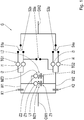
- Fig. 1 shows an abstract representation of a transmission G.
- the transmission G has a drive shaft GW1, a first and a second partial transmission TG1, TG2, unsynchronized positive-locking clutches S1a, S2a, S3a, S4a, S5a and an output shaft GW2.
- the first sub-transmission TG1 is assigned a first input shaft W1, which can be connected to the drive shaft GW1 by engaging a first input clutch K1.
- the second sub-transmission TG2 is assigned a second input shaft W2, which can be connected to the drive shaft GW1 by engaging a second input clutch K2.
- Both partial transmissions TG1, TG2 are connected on the output side to the output shaft GW2.
- Gear ratios i1, i2 are assigned to the first partial transmission TG1.
- Gear ratios i3, i4 are assigned to the second partial transmission TG2.
- the gear ratios i1, i2, i3, i4 are designed, for example, as spur gear stages, and have mutually different gear ratios.
- the clutch S5a connects the two sub-transmissions TG1, TG2, so that a power flow from the drive shaft GW1 to the output shaft GW2 runs via transmission stages i2, i3 of both sub-transmissions TG1, TG2.
- Such a formed path is also referred to as a winding path.
- the transmission G further has a first and a second switchable torque transmission path L1, L2 between the input shafts W1, W2.
- the first torque transmission path L1 comprises a first clutch Z1 and a first transmission ratio iZ1.
- the second torque transmission path L2 comprises a second clutch Z2 and a second transmission ratio iZ2.
- the first clutch Z1 and the second clutch Z2 are each designed as friction clutches.
- the two torque transmission paths L1, L2 serve to synchronize the clutches S1a, S2a, S3a, S4a, S5a.
- a torque MZ1, MZ2 can be transmitted from the first input shaft W1 to the second input shaft W2 by the appropriate control of the first clutch Z1 or the second clutch Z2 by the second input shaft W2 Accelerate or decelerate to a target speed as required, in order to be able to close the clutch S3a, for example, when the input clutch K2 is open.
- the two gear ratios iZ1, iZ2 are different from each other.
- the first torque transmission path L1 is used to accelerate the second input shaft W2 in relation to a rotational speed of the first input shaft W1
- the second torque transmission path L2 is used to decelerate the second input shaft W2 in relation to the rotational speed of the first input shaft W1. If the second input shaft W2 has reached its target speed, the clutch S3a can be closed. A gear change can now take place by simultaneously opening the first input clutch K1 and closing the second input clutch K2 without interrupting the tensile force between the input shaft GW1 and the output shaft GW2.
- the indicated arrow directions of the torques MZ1, MZ2 are only for illustration and are not restrictive.
- the two torque transmission paths L1, L2 serve to accelerate or brake the first input shaft W1 to a target speed.
- the first torque transmission path L1 now serves to decelerate the first input shaft W1 in relation to the speed of the second input shaft W2, and the second torque transmission path L2 now serves to accelerate the first input shaft W1 in relation to the speed of the second input shaft W2.
- the shift clutches S1a, S2a, S3a, S4a, S5a to be closed can be synchronized both in an upshift process and in a downshift process.
- the two torque transmission paths L1, L2 are not used here for gear formation.
- at least one of the torque transmission paths L1, L2 can also be used for gear formation.
- One of the two torque transmission paths L1, L2 can optionally be omitted.
- some of the clutches S1a, S2a, S3a, S4a, S5a can be provided with a conventional locking synchronization, so that the synchronization in certain gear shifts can also take place without using the torque transmission paths L1, L2.
- an electrical machine could be connected to one of the input shafts W1, W2, which can be used for synchronization.
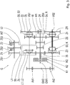
- Fig. 2 shows a first embodiment of the transmission G.
- the input clutches K1, K2 are arranged coaxially to one another.
- the second input shaft W2 is accordingly designed as a hollow shaft, and encloses the first input shaft W1 at least in sections.
- Three gearwheels ZS, 46, 2R designed as fixed gears are arranged on the first input shaft W1.
- a gear 35 designed as a fixed gear is arranged on the second input shaft W2.
- the transmission G has two countershafts VG1, VG2.
- Three gearwheels Z5, Z6, Z2 designed as idler gears are arranged on the first countershaft VG1.
- Three gearwheels Z3, Z4, ZR designed as idler gears are arranged on the second countershaft VG2.
- the transmission G comprises seven clutches, which are designated as S5, S6, S2, S3, S4, SR, K.
- S5, the idler gear 5 is connected to the first countershaft VG1.
- the gear Z6 is connected to the first countershaft VG1.
- the gear Z2 is connected to the first countershaft VG1.
- the gear Z3 is connected to the second countershaft VG2.
- the gear Z4 is connected to the second countershaft VG2.
- the clutch SR the gear ZR is connected to the second countershaft VG2.
- the gear Z3 is connected to the gear Z4.
- the actuation that is to say the opening and closing of the switching clutches S5, S6, S2, S3, S4, SR, K, is carried out by an actuator system AK, for example by means of shift rods.
- the gear 35 meshes with the gears Z5 and Z3.
- the gear 46 meshes with the gear Z4 and Z6.
- Gear 2R meshes with gear Z2 and over Fig. 1 idler gear, not shown, which meshes with the ZR gear.
- Both countershafts VG1, VG2 are connected to the output shaft GW2 via spur gear stages Ab1, Ab2.
- the transmission G also has a further shaft WZ, which is arranged axially parallel to the input shafts W1, W2 and axially parallel to the countershafts VG1, VG2.
- Three gears ZS1, ZS2, ZS3 are assigned to the further shaft.
- the gear ZS1 is designed as a fixed gear.
- the gears ZS2, ZS3 are designed as idler gears.
- Torque is transmitted between gear ZS2 and the further shaft WZ by engaging a first clutch Z1.
- a torque transmission between gear ZS3 and the further shaft WZ takes place by closing a second clutch Z2.
- the clutches Z1, Z2 are arranged coaxially to the further shaft WZ.
- the gears ZS1, ZS2, ZS3 and the clutches Z1, Z2 are part of two switchable torque transmission paths L1, L2 between the two input shafts W1, W2.
- the two torque transmission paths are formed by a first gear pair, a second gear pair and a third gear pair.
- the first gear pair results from the gear wheels 35 and ZS1.
- the second gear pair results from the gears ZS and ZS2.
- the third gear pair results from the gear wheels 46 and ZS3.
- the gears 35, ZS1; ZS, ZS2; 46, ZS3 of the respective gear pairs mesh with one another.
- the first gear pair is part of both torque transmission paths L1, L2.
- the second gear pair is part of the first torque transmission path L1.
- the second gear pair is part of the second torque transmission path L2.
- the gear ZS which is part of the second gear pair and thus the first torque transmission path L1 does not contribute to the formation of gears, but only serves to form the first torque transmission path L1.
- the gearwheel ZS is preferably connected in one piece to the gearwheel 46, and is arranged axially between the gearwheels 35 and 46.
- Fig. 3 shows a second embodiment of the transmission G, which essentially in the Fig. 2 illustrated first embodiment corresponds.
- the transmission G now has an additional gear ZSX, which is designed as a fixed gear of the first input shaft W1.
- the additional gear ZSX meshes with the gear ZS3 instead of the gear 46 and is therefore part of the second torque transmission path L2 and is not involved in gear formation.
- the additional gear ZSX is arranged axially between the gear ZS and the gear 46.
- the actuator system AK is in Fig. 3 not shown for the sake of clarity.
- Fig. 4 shows a shift table, which is applicable for both embodiments of the transmission G.
- gears 1 to 7, R1, R2 are listed in the order of their gear row.
- the clutches S5, S6, S2, S3, S4, SR, K and the input clutches K1, K2 are listed in the columns. Circles indicate the closed state of the clutches S5, S6, S2, S3, S4, SR, K and the input clutches K1, K2 in gears 1 to 7, R1, R2.
- the circuit diagram clearly shows that the two clutches Z1, Z2, and thus the two torque transmission paths L1, L2 do not contribute to the gear formation of the transmission G.
- the increments between adjacent gears of the transmission G in the gear row are preferably not identical.
- the increment between gear 1 and gear 2 is greater than the increment between gear 5 and gear 6.
- Such a degressive gear gradation is advantageous for use in a motor vehicle drive train.
- the transmission ratio iZ1, iZ2 of at least one, preferably both, of the torque transmission paths L1, L2 is, by way of example, greater than the largest step jump between gears of the same direction of rotation that are adjacent in the gear row.
- Gears in the same direction of rotation refer to gears in which the input shaft GW1 and the output shaft GW2 have the same direction of rotation.
- gear 3 is engaged in the transmission G, after which the input clutch K2 and the clutch S3 are closed.
- the clutch S2 is closed and the input clutch K1 is open.
- the clutch S2 is to be opened and the clutch S4 is to be closed, in order to only have to open the input clutch K2 and to close the input clutch K1 for a subsequent upshift from gear 3 to gear 4.
- the clutch S2 is not load-free, however, since the drag torque of the opened input clutch K1 acts on the output shaft GW2 via the load path of gear 2.
- the drag torque acting on the clutch S2 is further increased by the gear ratio between the gear 2R and the gear Z2.
- the friction clutch Z2 can be actuated, so that a torque MZ2 is transmitted via the torque transmission path L2. Due to the transmission ratio iZ2 of the torque transmission path L2, the torque MZ2 counteracts the drag torque at the input clutch K1, so that the torque load on the still engaged clutch S2 is reduced. Now the clutch clutch S2 can be opened with little effort by the actuator system AK. With sufficiently precise control and a sufficiently high gear ratio iZ2, the clutch S2 can even be made completely load-free by actuating the friction clutch Z2.
- the first or the second friction clutch Z1, Z2 is actuated. Due to the different transmission ratios iZ1, iZ2 of the torque transmission paths L1, L2, the load on the shift clutch to be opened can be reduced accordingly. In the same way, one of the torque transmission paths L1, L2 can be used to reduce the load on a clutch to be closed.
- Fig. 5 shows a drive train for a motor vehicle.
- an internal combustion engine VKM is connected to the transmission G via an intermediate torsional vibration damper TS.
- a differential gear AG is connected downstream of the gearbox G, via which a drive power on drive wheels DW a drive axle of the motor vehicle is distributed.
- the gearbox G and the torsional vibration damper TS are arranged in a common housing of the gearbox G, in which the differential gear AG can then also be integrated.
- the internal combustion engine VKM, the torsional vibration damper TS, the gearbox G and also the differential gear AG are oriented transversely to a direction of travel of the motor vehicle.
- the transmission G comprises a control unit ECU, which is set up at least to control the actuator system AK and to control the frictional clutches Z1, Z2.
- a map can be stored on the control unit ECU, which is used to control the frictional clutches Z1, Z2.
Claims (15)
- Transmission (G) destinée à un véhicule automobile, la transmission (G) comportant un arbre d'entraînement (GW1), un premier arbre d'entrée (W1) qui peut être relié à l'arbre d'entraînement (GW1) par le biais d'un premier embrayage d'entrée (K1), un deuxième arbre d'entrée (W2) qui peut être relié à l'arbre d'entraînement (GW1) par le biais d'un deuxième embrayage d'entrée (K2), une pluralité d'embrayages (Sla, S2a, S3a, S4a, S5a ; S2, S3, S4, S5, S6, SR, K) et un arbre de sortie (GW2),- différents rapports de vitesse (1 à 7, R1, R2) entre l'arbre d'entraînement (GW1) et l'arbre de sortie (GW2) pouvant être obtenus par actionnement sélectif des embrayages (S5, S6, S2, S3, S4, SR, K) et des embrayages d'entrée (K1, K2),- au moins un premier chemin de transmission de couple (L1) commutable au moyen d'un embrayage à friction (Z1) étant prévu entre le premier arbre d'entrée (W1) et le deuxième arbre d'entrée (W2), caractérisée en ce qu'un rapport de transmission (iZ1) du premier chemin de transmission de couple (L1) entre les arbres d'entrée (W1, W2) est supérieur au plus grand écart entre deux rapports de vitesse (1 à 7) de même sens de rotation qui sont adjacents dans une rangée de rapports de vitesse.
- Transmission (G) selon la revendication 1, caractérisée en ce qu'un deuxième chemin de transmission de couple (L2) commutable au moyen d'un autre embrayage à friction (Z2) est prévu entre le premier arbre d'entrée (W1) et le deuxième arbre d'entrée (W2), un rapport de transmission (iZ2) du deuxième chemin de transmission de couple (L2) entre les arbres d'entrée (W1, W2) étant supérieur au plus grand écart entre deux rapports de vitesse (1 à 7) de du même sens de rotation qui sont adjacents dans la rangée de rapports de vitesse.
- Transmission (G) selon la revendication 1 ou la revendication 2, caractérisée en ce qu'au moins une partie des embrayages (Sla, S2a, S3a, S4a, S5a ; S2, S3, S4, S5, S6, SR, K) sont conçus comme des éléments de commutation à complémentarité de formes non synchronisés.
- Chaîne cinématique pour véhicule automobile, caractérisée par une transmission (G) selon l'une des revendications 1 à 3.
- Procédé de fonctionnement d'une transmission (G) destinée à un véhicule automobile, la transmission (G) comportant un arbre d'entraînement (GW1), un premier arbre d'entrée (W1) qui peut être relié à l'arbre d'entraînement (GW1) par le biais d'un premier embrayage d'entrée (K1), un deuxième arbre d'entrée (W2) qui peut être relié à l'arbre d'entraînement (GW1) par le biais d'un deuxième embrayage d'entrée (K2), une pluralité d'embrayages (Sla, S2a, S3a, S4a, S5a ; S2, S3, S4, S5, S6, SR, K) et un arbre de sortie (GW2),- différents rapports de vitesse (1 à 7, R1, R2) entre l'arbre d'entraînement (GW1) et l'arbre de sortie (GW2) pouvant être obtenus par actionnement sélectif des embrayages (Sla, S2a, S3a, S4a, S5a ; S2, S3, S4, S5, S6, SR, K) et des embrayages d'entrée (K1, K2),- au moins un premier chemin de transmission de couple (L1) commutable au moyen d'un embrayage à friction (Z1) étant prévu entre le premier arbre d'entrée (W1) et le deuxième arbre d'entrée (W2), caractérisé en ce que l'embrayage à friction (Z1) est actionné simultanément à une commande d'un système d'actionneur (AK) destiné à ouvrir l'un au moins des embrayages (S1a, S2a, S3a, S4a, S5a ; S2, S3, S4, S5, S6, SR, K) afin de transmettre un couple (MZ1) entre les arbres d'entrée (W1, W2), de façon à réduire le couple d'actionnement agissant entre les moitiés de l'embrayage (S1a, S2a, S3a, S4a, S5a ; S2, S3, S4, S5, S6, SR, K) à ouvrir.
- Procédé selon la revendication 5, caractérisé en ce qu'un deuxième chemin de transmission de couple (L2), commutable au moyen d'un autre embrayage à friction (Z2), est prévu entre le premier arbre d'entrée (W1) et le deuxième arbre d'entrée (W2), l'un des deux embrayages à friction (Z1, Z2) étant actionné simultanément à une commande destinée à ouvrir l'un au moins des embrayages (Sla, S2a, S3a, S4a, S5a ; S2, S3, S4, S5, S6, SR, K) à ouvrir afin de transmettre un couple (MZ1, MZ2) entre les arbres d'entrée (W1, W2), de façon à réduire le couple d'actionnement agissant entre les moitiés de l'embrayage (Sla, S2a, S3a, S4a, S5a ; S2, S3, S4, S5, S6, SR, K) à ouvrir.
- Procédé selon la revendication 5 ou la revendication 6, caractérisé en ce que l'un des embrayages à friction (Z1, Z2) est actionné de telle sorte que l'embrayage (Sla, S2a, S3a, S4a, S5a ; S2, S3, S4, S5, S6, SR, K) à ouvrir devienne sans charge.
- Procédé selon l'une des revendications 5 à 7, caractérisé en ce que l'un des embrayage à friction (Z1, Z2) est actionné lors d'une commande pour fermer l'un au moins des embrayages (Sla, S2a, S3a, S4a, S5a ; S2, S3, S4, S5, S6, SR, K) afin de transmettre un couple (MZ1, MZ2) entre les arbres d'entrée (W1, W2) de façon à réduire le couple d'actionnement agissant entre les moitiés de l'embrayage (Sla, S2a, S3a, S4a, S5a ; S2, S3, S4, S5, S6, SR, K) à ouvrir.
- Procédé selon l'une des revendications 5 à 8, caractérisé en ce que le couple (MZ1, MZ2) à transmettre par l'embrayage à friction (Z1, Z2) est déterminé à partir d'un diagramme caractéristique.
- Procédé selon la revendication 9, caractérisé en ce que le diagramme caractéristique est adapté pendant le fonctionnement de la transmission (G).
- Procédé selon la revendication 10, caractérisé en ce que l'adaptation du diagramme caractéristique est effectuée en dehors des processus de commutation de la transmission (G).
- Procédé selon l'une des revendications 5 à 11, caractérisé en ce que, lors de l'actionnement de l'un au moins des embrayages (Sla, S2a, S3a, S4a, S5a ; S2, S3, S4, S5, S6, SR, K), un mouvement relatif dans une direction d'actionnement entre les moitiés de cet embrayage (S1a, S2a, S3a, S4a, S5a ; S2, S3, S4, S5, S6, SR, K) est surveillée, une valeur du couple (MZ1, MZ2), qui est transmis par l'embrayage à friction (Z1, Z2) actionné à chaque fois, est augmentée seulement si le mouvement relatif ne commence pas dans un intervalle de temps prédéterminé ou n'atteint ni ne dépasse une distance définie.
- Procédé selon la revendication 12, selon lequel l'augmentation de la valeur du couple (MZ1, MZ2) est accélérée.
- Procédé selon l'une des revendications 5 à 13, caractérisé en ce qu'un rapport de transmission (iZ1, iZ2) de l'un des chemins de transmission de couple (L1, L2) entre les arbres d'entrée (W1, W2) est supérieur au plus grand écart entre deux rapports de vitesse (1 à 7) de même sens de rotation qui sont adjacents dans une rangée rapports de vitesses.
- Unité de commande (ECU) destinée à une transmission de véhicule automobile (G), caractérisée en ce que l'unité de commande (ECU) est conçue pour commander le procédé selon l'une des revendications 5 à 14.
Priority Applications (1)
| Application Number | Priority Date | Filing Date | Title |
|---|---|---|---|
| EP17207313.2A EP3499088B1 (fr) | 2017-12-14 | 2017-12-14 | Boîte de vitesses de véhicule automobile et procédé de fonctionnement d'une telle boîte de vitesses |
Applications Claiming Priority (1)
| Application Number | Priority Date | Filing Date | Title |
|---|---|---|---|
| EP17207313.2A EP3499088B1 (fr) | 2017-12-14 | 2017-12-14 | Boîte de vitesses de véhicule automobile et procédé de fonctionnement d'une telle boîte de vitesses |
Publications (2)
| Publication Number | Publication Date |
|---|---|
| EP3499088A1 EP3499088A1 (fr) | 2019-06-19 |
| EP3499088B1 true EP3499088B1 (fr) | 2020-07-01 |
Family
ID=60673565
Family Applications (1)
| Application Number | Title | Priority Date | Filing Date |
|---|---|---|---|
| EP17207313.2A Active EP3499088B1 (fr) | 2017-12-14 | 2017-12-14 | Boîte de vitesses de véhicule automobile et procédé de fonctionnement d'une telle boîte de vitesses |
Country Status (1)
| Country | Link |
|---|---|
| EP (1) | EP3499088B1 (fr) |
Families Citing this family (1)
| Publication number | Priority date | Publication date | Assignee | Title |
|---|---|---|---|---|
| DE102018208764A1 (de) * | 2018-06-04 | 2019-12-05 | Zf Friedrichshafen Ag | Verfahren zum Betrieb eines Getriebes |
Family Cites Families (6)
| Publication number | Priority date | Publication date | Assignee | Title |
|---|---|---|---|---|
| DE4436526A1 (de) * | 1994-04-16 | 1995-10-19 | Rudolf Prof Dr Franke | Verfahren zur Synchronisierung der Schaltkupplungen eines Stirnradwechselgetriebes für ein Kraftfahrzeug und Stirnradwechselgetriebe zur Durchführung des Verfahrens |
| DE10225331A1 (de) | 2001-07-15 | 2003-12-24 | Richard Boisch | Lastschaltgetriebe mit Zentralsynchronisiertung |
| DE10239540A1 (de) * | 2001-07-15 | 2004-03-11 | Boisch, Richard, Prof. Dr. | Rückwärtsgang und Zentralsynchronisierung für Lastschaltgetriebe |
| DE10214478B4 (de) * | 2002-03-30 | 2004-04-15 | Zf Sachs Ag | Synchronisiereinrichtung für ein Doppelkupplungsgetriebe auf Grundlage wenigstens zweier Planetenradsätze und entsprechendes Doppelkupplungsgetriebe, sowie entprechender Kraftfahrzeug-Antriebsstrang |
| DE10243278A1 (de) * | 2002-09-18 | 2004-03-25 | Volkswagen Ag | Vorrichtung zur Synchronisierung eines Doppelkupplungsgetriebes |
| AT511631B1 (de) | 2011-06-30 | 2013-04-15 | Avl List Gmbh | Doppelkupplungs-getriebe mit mehreren schaltbaren gangstufen |
-
2017
- 2017-12-14 EP EP17207313.2A patent/EP3499088B1/fr active Active
Non-Patent Citations (1)
| Title |
|---|
| None * |
Also Published As
| Publication number | Publication date |
|---|---|
| EP3499088A1 (fr) | 2019-06-19 |
Similar Documents
| Publication | Publication Date | Title |
|---|---|---|
| DE102017219835A1 (de) | Verfahren zur Steuerung eines Schaltvorgangs eines Fahrzeugs mit einem Doppelkupplungsgetriebe | |
| EP2818748B1 (fr) | Procédé de commande d'une boîte de vitesses à double embrayage | |
| DE102014016932A1 (de) | Verfahren zum Schalten eines Gruppengetriebes eines Kraftwagens | |
| DE102009000254A1 (de) | Verfahren zum Betreiben einer Getriebevorrichtung eines Fahrzeugantribsstranges | |
| EP2457760A2 (fr) | Conducteur de commande et procédé de fonctionnement de celui-ci | |
| DE102014209970B4 (de) | Getriebe für ein Kraftfahrzeug | |
| EP2921746B1 (fr) | Procédé de commande d'une chaîne cinématique et chaîne cinématique | |
| DE102009045485A1 (de) | Verfahren zum Betreiben einer Antriebsvorrichtung, Antriebsvorrichtung | |
| EP3303880B1 (fr) | Groupe-relais pour un véhicule à moteur et procédé pour faire fonctionner un groupe-relais de ce type | |
| WO2001074619A2 (fr) | Boite de vitesses | |
| DE102017004681A1 (de) | Ändern einer Übersetzung in einem Getriebe eines Fahrzeugs | |
| EP3499088B1 (fr) | Boîte de vitesses de véhicule automobile et procédé de fonctionnement d'une telle boîte de vitesses | |
| EP1096172A2 (fr) | Transmission de changement de vitesse sous charge automatisée et sa méthode de commande | |
| AT512917B1 (de) | Verfahren zum Betreiben eines Doppelkupplungsgetriebes | |
| DE102016106206A1 (de) | Ansteuerungsverfahren für Antriebsstrang und Getriebeanordnung für Antriebsstrang | |
| WO2005008103A1 (fr) | Procede de commutation d'une boite de vitesses a double embrayage d'automobile | |
| DE102014019011A1 (de) | Stufengetriebe für einen Kraftwagen, insbesondere einen Nutzkraftwagen | |
| DE102013221912A1 (de) | Getriebe-Motor-Anordnung | |
| DE102019219954B4 (de) | Verfahren zur Schaltsteuerung eines automatisierten Gruppengetriebes | |
| DE102017222765A1 (de) | Getriebe für ein Kraftfahrzeug, und Verfahren zum Betrieb eines solchen Getriebes | |
| DE102013010013A1 (de) | Verfahren und Vorrichtung zur Steuerung eines Schaltgetriebes | |
| DE102017004637B4 (de) | Ändern einer Übersetzung in einem Getriebe eines Fahrzeugs | |
| DE102017222724B4 (de) | Getriebe für ein Kraftfahrzeug | |
| DE102010024768A1 (de) | Kraftfahrzeuggruppengetriebevorrichtung | |
| DE102014219099A1 (de) | Verfahren zur Schaltsteuerung eines automatisierten Schaltgetriebes in einem elektromotorisch angetriebenen Fahrzeug |
Legal Events
| Date | Code | Title | Description |
|---|---|---|---|
| PUAI | Public reference made under article 153(3) epc to a published international application that has entered the european phase |
Free format text: ORIGINAL CODE: 0009012 |
|
| STAA | Information on the status of an ep patent application or granted ep patent |
Free format text: STATUS: THE APPLICATION HAS BEEN PUBLISHED |
|
| AK | Designated contracting states |
Kind code of ref document: A1 Designated state(s): AL AT BE BG CH CY CZ DE DK EE ES FI FR GB GR HR HU IE IS IT LI LT LU LV MC MK MT NL NO PL PT RO RS SE SI SK SM TR |
|
| AX | Request for extension of the european patent |
Extension state: BA ME |
|
| STAA | Information on the status of an ep patent application or granted ep patent |
Free format text: STATUS: REQUEST FOR EXAMINATION WAS MADE |
|
| 17P | Request for examination filed |
Effective date: 20191206 |
|
| GRAP | Despatch of communication of intention to grant a patent |
Free format text: ORIGINAL CODE: EPIDOSNIGR1 |
|
| STAA | Information on the status of an ep patent application or granted ep patent |
Free format text: STATUS: GRANT OF PATENT IS INTENDED |
|
| INTG | Intention to grant announced |
Effective date: 20200131 |
|
| GRAS | Grant fee paid |
Free format text: ORIGINAL CODE: EPIDOSNIGR3 |
|
| GRAA | (expected) grant |
Free format text: ORIGINAL CODE: 0009210 |
|
| STAA | Information on the status of an ep patent application or granted ep patent |
Free format text: STATUS: THE PATENT HAS BEEN GRANTED |
|
| AK | Designated contracting states |
Kind code of ref document: B1 Designated state(s): AL AT BE BG CH CY CZ DE DK EE ES FI FR GB GR HR HU IE IS IT LI LT LU LV MC MK MT NL NO PL PT RO RS SE SI SK SM TR |
|
| REG | Reference to a national code |
Ref country code: AT Ref legal event code: REF Ref document number: 1286485 Country of ref document: AT Kind code of ref document: T Effective date: 20200715 Ref country code: CH Ref legal event code: EP |
|
| REG | Reference to a national code |
Ref country code: IE Ref legal event code: FG4D Free format text: LANGUAGE OF EP DOCUMENT: GERMAN |
|
| REG | Reference to a national code |
Ref country code: DE Ref legal event code: R096 Ref document number: 502017005964 Country of ref document: DE |
|
| REG | Reference to a national code |
Ref country code: LT Ref legal event code: MG4D |
|
| PG25 | Lapsed in a contracting state [announced via postgrant information from national office to epo] |
Ref country code: BG Free format text: LAPSE BECAUSE OF FAILURE TO SUBMIT A TRANSLATION OF THE DESCRIPTION OR TO PAY THE FEE WITHIN THE PRESCRIBED TIME-LIMIT Effective date: 20201001 |
|
| REG | Reference to a national code |
Ref country code: NL Ref legal event code: MP Effective date: 20200701 |
|
| PG25 | Lapsed in a contracting state [announced via postgrant information from national office to epo] |
Ref country code: LT Free format text: LAPSE BECAUSE OF FAILURE TO SUBMIT A TRANSLATION OF THE DESCRIPTION OR TO PAY THE FEE WITHIN THE PRESCRIBED TIME-LIMIT Effective date: 20200701 Ref country code: CZ Free format text: LAPSE BECAUSE OF FAILURE TO SUBMIT A TRANSLATION OF THE DESCRIPTION OR TO PAY THE FEE WITHIN THE PRESCRIBED TIME-LIMIT Effective date: 20200701 Ref country code: HR Free format text: LAPSE BECAUSE OF FAILURE TO SUBMIT A TRANSLATION OF THE DESCRIPTION OR TO PAY THE FEE WITHIN THE PRESCRIBED TIME-LIMIT Effective date: 20200701 Ref country code: PT Free format text: LAPSE BECAUSE OF FAILURE TO SUBMIT A TRANSLATION OF THE DESCRIPTION OR TO PAY THE FEE WITHIN THE PRESCRIBED TIME-LIMIT Effective date: 20201102 Ref country code: SE Free format text: LAPSE BECAUSE OF FAILURE TO SUBMIT A TRANSLATION OF THE DESCRIPTION OR TO PAY THE FEE WITHIN THE PRESCRIBED TIME-LIMIT Effective date: 20200701 Ref country code: ES Free format text: LAPSE BECAUSE OF FAILURE TO SUBMIT A TRANSLATION OF THE DESCRIPTION OR TO PAY THE FEE WITHIN THE PRESCRIBED TIME-LIMIT Effective date: 20200701 Ref country code: NO Free format text: LAPSE BECAUSE OF FAILURE TO SUBMIT A TRANSLATION OF THE DESCRIPTION OR TO PAY THE FEE WITHIN THE PRESCRIBED TIME-LIMIT Effective date: 20201001 Ref country code: GR Free format text: LAPSE BECAUSE OF FAILURE TO SUBMIT A TRANSLATION OF THE DESCRIPTION OR TO PAY THE FEE WITHIN THE PRESCRIBED TIME-LIMIT Effective date: 20201002 Ref country code: FI Free format text: LAPSE BECAUSE OF FAILURE TO SUBMIT A TRANSLATION OF THE DESCRIPTION OR TO PAY THE FEE WITHIN THE PRESCRIBED TIME-LIMIT Effective date: 20200701 |
|
| PG25 | Lapsed in a contracting state [announced via postgrant information from national office to epo] |
Ref country code: IS Free format text: LAPSE BECAUSE OF FAILURE TO SUBMIT A TRANSLATION OF THE DESCRIPTION OR TO PAY THE FEE WITHIN THE PRESCRIBED TIME-LIMIT Effective date: 20201101 Ref country code: PL Free format text: LAPSE BECAUSE OF FAILURE TO SUBMIT A TRANSLATION OF THE DESCRIPTION OR TO PAY THE FEE WITHIN THE PRESCRIBED TIME-LIMIT Effective date: 20200701 Ref country code: LV Free format text: LAPSE BECAUSE OF FAILURE TO SUBMIT A TRANSLATION OF THE DESCRIPTION OR TO PAY THE FEE WITHIN THE PRESCRIBED TIME-LIMIT Effective date: 20200701 Ref country code: RS Free format text: LAPSE BECAUSE OF FAILURE TO SUBMIT A TRANSLATION OF THE DESCRIPTION OR TO PAY THE FEE WITHIN THE PRESCRIBED TIME-LIMIT Effective date: 20200701 |
|
| PG25 | Lapsed in a contracting state [announced via postgrant information from national office to epo] |
Ref country code: NL Free format text: LAPSE BECAUSE OF FAILURE TO SUBMIT A TRANSLATION OF THE DESCRIPTION OR TO PAY THE FEE WITHIN THE PRESCRIBED TIME-LIMIT Effective date: 20200701 |
|
| REG | Reference to a national code |
Ref country code: DE Ref legal event code: R097 Ref document number: 502017005964 Country of ref document: DE |
|
| PG25 | Lapsed in a contracting state [announced via postgrant information from national office to epo] |
Ref country code: DK Free format text: LAPSE BECAUSE OF FAILURE TO SUBMIT A TRANSLATION OF THE DESCRIPTION OR TO PAY THE FEE WITHIN THE PRESCRIBED TIME-LIMIT Effective date: 20200701 Ref country code: RO Free format text: LAPSE BECAUSE OF FAILURE TO SUBMIT A TRANSLATION OF THE DESCRIPTION OR TO PAY THE FEE WITHIN THE PRESCRIBED TIME-LIMIT Effective date: 20200701 Ref country code: SM Free format text: LAPSE BECAUSE OF FAILURE TO SUBMIT A TRANSLATION OF THE DESCRIPTION OR TO PAY THE FEE WITHIN THE PRESCRIBED TIME-LIMIT Effective date: 20200701 Ref country code: EE Free format text: LAPSE BECAUSE OF FAILURE TO SUBMIT A TRANSLATION OF THE DESCRIPTION OR TO PAY THE FEE WITHIN THE PRESCRIBED TIME-LIMIT Effective date: 20200701 Ref country code: IT Free format text: LAPSE BECAUSE OF FAILURE TO SUBMIT A TRANSLATION OF THE DESCRIPTION OR TO PAY THE FEE WITHIN THE PRESCRIBED TIME-LIMIT Effective date: 20200701 |
|
| PLBE | No opposition filed within time limit |
Free format text: ORIGINAL CODE: 0009261 |
|
| STAA | Information on the status of an ep patent application or granted ep patent |
Free format text: STATUS: NO OPPOSITION FILED WITHIN TIME LIMIT |
|
| PG25 | Lapsed in a contracting state [announced via postgrant information from national office to epo] |
Ref country code: AL Free format text: LAPSE BECAUSE OF FAILURE TO SUBMIT A TRANSLATION OF THE DESCRIPTION OR TO PAY THE FEE WITHIN THE PRESCRIBED TIME-LIMIT Effective date: 20200701 |
|
| 26N | No opposition filed |
Effective date: 20210406 |
|
| PG25 | Lapsed in a contracting state [announced via postgrant information from national office to epo] |
Ref country code: SK Free format text: LAPSE BECAUSE OF FAILURE TO SUBMIT A TRANSLATION OF THE DESCRIPTION OR TO PAY THE FEE WITHIN THE PRESCRIBED TIME-LIMIT Effective date: 20200701 |
|
| REG | Reference to a national code |
Ref country code: CH Ref legal event code: PL |
|
| PG25 | Lapsed in a contracting state [announced via postgrant information from national office to epo] |
Ref country code: MC Free format text: LAPSE BECAUSE OF FAILURE TO SUBMIT A TRANSLATION OF THE DESCRIPTION OR TO PAY THE FEE WITHIN THE PRESCRIBED TIME-LIMIT Effective date: 20200701 Ref country code: SI Free format text: LAPSE BECAUSE OF FAILURE TO SUBMIT A TRANSLATION OF THE DESCRIPTION OR TO PAY THE FEE WITHIN THE PRESCRIBED TIME-LIMIT Effective date: 20200701 |
|
| REG | Reference to a national code |
Ref country code: BE Ref legal event code: MM Effective date: 20201231 |
|
| PG25 | Lapsed in a contracting state [announced via postgrant information from national office to epo] |
Ref country code: LU Free format text: LAPSE BECAUSE OF NON-PAYMENT OF DUE FEES Effective date: 20201214 Ref country code: IE Free format text: LAPSE BECAUSE OF NON-PAYMENT OF DUE FEES Effective date: 20201214 |
|
| PG25 | Lapsed in a contracting state [announced via postgrant information from national office to epo] |
Ref country code: LI Free format text: LAPSE BECAUSE OF NON-PAYMENT OF DUE FEES Effective date: 20201231 Ref country code: CH Free format text: LAPSE BECAUSE OF NON-PAYMENT OF DUE FEES Effective date: 20201231 |
|
| PG25 | Lapsed in a contracting state [announced via postgrant information from national office to epo] |
Ref country code: TR Free format text: LAPSE BECAUSE OF FAILURE TO SUBMIT A TRANSLATION OF THE DESCRIPTION OR TO PAY THE FEE WITHIN THE PRESCRIBED TIME-LIMIT Effective date: 20200701 Ref country code: MT Free format text: LAPSE BECAUSE OF FAILURE TO SUBMIT A TRANSLATION OF THE DESCRIPTION OR TO PAY THE FEE WITHIN THE PRESCRIBED TIME-LIMIT Effective date: 20200701 Ref country code: CY Free format text: LAPSE BECAUSE OF FAILURE TO SUBMIT A TRANSLATION OF THE DESCRIPTION OR TO PAY THE FEE WITHIN THE PRESCRIBED TIME-LIMIT Effective date: 20200701 |
|
| PG25 | Lapsed in a contracting state [announced via postgrant information from national office to epo] |
Ref country code: MK Free format text: LAPSE BECAUSE OF FAILURE TO SUBMIT A TRANSLATION OF THE DESCRIPTION OR TO PAY THE FEE WITHIN THE PRESCRIBED TIME-LIMIT Effective date: 20200701 |
|
| PG25 | Lapsed in a contracting state [announced via postgrant information from national office to epo] |
Ref country code: BE Free format text: LAPSE BECAUSE OF NON-PAYMENT OF DUE FEES Effective date: 20201231 |
|
| GBPC | Gb: european patent ceased through non-payment of renewal fee |
Effective date: 20211214 |
|
| PG25 | Lapsed in a contracting state [announced via postgrant information from national office to epo] |
Ref country code: GB Free format text: LAPSE BECAUSE OF NON-PAYMENT OF DUE FEES Effective date: 20211214 |
|
| P01 | Opt-out of the competence of the unified patent court (upc) registered |
Effective date: 20230528 |
|
| PGFP | Annual fee paid to national office [announced via postgrant information from national office to epo] |
Ref country code: FR Payment date: 20231009 Year of fee payment: 7 Ref country code: DE Payment date: 20231017 Year of fee payment: 7 |
|
| REG | Reference to a national code |
Ref country code: AT Ref legal event code: MM01 Ref document number: 1286485 Country of ref document: AT Kind code of ref document: T Effective date: 20221214 |