EP3499047A1 - Gebläsegehäuse und gebläse für ein haushaltsgerät - Google Patents
Gebläsegehäuse und gebläse für ein haushaltsgerät Download PDFInfo
- Publication number
- EP3499047A1 EP3499047A1 EP18211974.3A EP18211974A EP3499047A1 EP 3499047 A1 EP3499047 A1 EP 3499047A1 EP 18211974 A EP18211974 A EP 18211974A EP 3499047 A1 EP3499047 A1 EP 3499047A1
- Authority
- EP
- European Patent Office
- Prior art keywords
- blower
- housing
- housing part
- receiving space
- fan
- Prior art date
- Legal status (The legal status is an assumption and is not a legal conclusion. Google has not performed a legal analysis and makes no representation as to the accuracy of the status listed.)
- Pending
Links
Images


Classifications
-
- F—MECHANICAL ENGINEERING; LIGHTING; HEATING; WEAPONS; BLASTING
- F04—POSITIVE - DISPLACEMENT MACHINES FOR LIQUIDS; PUMPS FOR LIQUIDS OR ELASTIC FLUIDS
- F04D—NON-POSITIVE-DISPLACEMENT PUMPS
- F04D29/00—Details, component parts, or accessories
- F04D29/40—Casings; Connections of working fluid
- F04D29/42—Casings; Connections of working fluid for radial or helico-centrifugal pumps
- F04D29/4206—Casings; Connections of working fluid for radial or helico-centrifugal pumps especially adapted for elastic fluid pumps
- F04D29/4226—Fan casings
-
- F—MECHANICAL ENGINEERING; LIGHTING; HEATING; WEAPONS; BLASTING
- F04—POSITIVE - DISPLACEMENT MACHINES FOR LIQUIDS; PUMPS FOR LIQUIDS OR ELASTIC FLUIDS
- F04D—NON-POSITIVE-DISPLACEMENT PUMPS
- F04D29/00—Details, component parts, or accessories
- F04D29/66—Combating cavitation, whirls, noise, vibration or the like; Balancing
- F04D29/661—Combating cavitation, whirls, noise, vibration or the like; Balancing especially adapted for elastic fluid pumps
- F04D29/663—Sound attenuation
- F04D29/664—Sound attenuation by means of sound absorbing material
Definitions
- the present invention relates to a blower housing and a blower for a household appliance with a blower housing.
- blowers that are used for example in household appliances, and in particular represent radial blower
- the fan or the fan wheels are housed in a blower housing.
- the blower housing serves to guide air from a suction opening to an outlet opening.
- a blower housing In the DE 10 2007 021 318 A1 such a blower housing is disclosed.
- a vapor extraction housing and an extractor hood are disclosed in this document.
- the extractor housing is designed to accommodate at least one fan housing and at least one fan wheel, in particular a radial fan, enclosed by the fan housing.
- the extractor housing also has a suction opening for receiving the vapors from a cooking place.
- the blower housing On one side of the blower housing, the blower housing on an air outlet or an air nozzle.
- the blower housing is a volute.
- the air outlet can be arranged at the top of the blower housing. Depending on the design of the blower and the position of the blower, the air outlet can also lie laterally on the blower housing.
- These known fan housing are usually made of sheet metal or plastic material that is reverberant.
- blower housing has a number of disadvantages.
- the sheet metal or plastic material can only take over the functions of the air duct.
- noises such as airborne or structure-borne noise, occur during operation of the fan, additional acoustic insulation is necessary.
- blower housings can only be manufactured with high material and tooling costs.
- the assembly, mounting and sealing of the blower housing is complex.
- the object of the present invention is therefore to provide a solution by means of which, with a simple construction of the blower housing, this can simultaneously serve for guiding the air and for reducing noise.
- the invention is based on the finding that this object can be achieved by the air duct of the blower housing is at least partially formed in a soundproofing material.
- the object is achieved by a fan housing for a fan, wherein the fan housing has a receiving space for at least one fan of the fan and an adjoining the receiving space air outlet.
- the blower housing is characterized in that the blower housing has a housing part which at least partially consists of soundproofing material and in the housing part at least the receiving space is at least partially formed by soundproofing material.
- the fan housing has a receiving space for at least one fan.
- the receiving space preferably has a round, oval or spiral cross-section.
- the fan is arranged in the receiving space so that a wall of the receiving space surrounds the circumference of the fan as far as possible.
- an air outlet opening is introduced, via which the air can flow from the receiving space into an air outlet channel.
- the air outlet channel preferably connects tangentially or radially to the cross section of the receiving space.
- the receiving space and the air outlet passage are collectively referred to as the air guiding space of the blower housing.
- the fan housing forms a so-called spiral housing.
- the fan housing In the axial direction of the fan wheel of the receiving space is preferably covered by one or more further housing parts of the blower housing.
- These further housing parts may have a construction corresponding to the first housing part or be designed, for example, as a cover plate.
- the air inlet opening may be provided for the fan and may for example be covered by a grid.
- the fan which has a fan housing according to the invention, is therefore preferably a radial fan.
- the blower housing is characterized in that the blower housing has a housing part, which consists at least partially of soundproofing material and in the device housing at least the receiving space is at least partially formed by soundproofing material.
- the housing part may represent a block of material or molded body.
- the housing part consists at least partially of soundproofing material.
- sound insulation material a material that is sound-absorbing and / or sound-insulating.
- Sound attenuation or sound absorption refers in particular to a hindrance of sound propagation.
- the sound attenuation takes place by obstructing the sound propagation through absorption of airborne sound.
- the impairment of the sound propagation of airborne sound or structure-borne noise into adjacent rooms is referred to as sound insulation by sound reflection of the propagating sound.
- the soundproofing material may in particular represent a soft sounding material.
- the soundproofing material may therefore represent a porous, elastic and / or fibrous material. Through these materials, in addition to the pure sound attenuation and or sound also vibration of the housing part is prevented with respect to other parts of the device housing or the household appliance and thus delivered a further sound insulation. It is particularly preferred to use a soundproofing material which can absorb and / or insulate sound at frequencies of 50 Hz to 10,000 Hz.
- the housing part can be made entirely of soundproofing material.
- elements of a dimensionally stable material are provided in or on the soundproofing material, which has no Schalldämpfung- or Schalldämmungsfunktionen.
- such elements may be made of metal and used to support the fan or the fan motor.
- the fan is mounted indirectly on the fan motor to the fan housing.
- the dimensions of the blower housing or the blower which are in the direction of the axis of rotation of the fan wheel in the finished blower, that is to say in the blower in which the blower is introduced into the blower housing, are referred to below as the height.
- details refer, as above and below to a fan in which the axis of rotation of the fan wheel, which is also referred to as the axis of rotation of the fan, lies in the vertical.
- Information such as axial and radial also refer to the axis of rotation of the fan.
- the receiving space is at least partially formed in the soundproofing material.
- at least the wall of the receiving space which surrounds the circumference of the fan of the blower, formed in the soundproofing material.
- one of the lying in the axial direction of the fan wheel walls of the receiving space may be formed in the soundproofing material.
- the housing part at least partially consists of soundproofing material and the receiving space is at least partially formed in the soundproofing material, a number of advantages can be achieved.
- noise reduction and / or sound insulation can take place by the blower housing itself.
- the manufacture of the fan is simplified by forming at least the receiving space in the soundproofing material.
- no complex alignment of the blower housing to an additional acoustic insulation is necessary.
- the housing part is a block of material which consists at least partially of soundproofing material.
- at least a part of the receiving space is produced by material removal in the material block.
- a body which at least partially consists of at least one soundproofing material and in which at least part of the receiving space for the fan of the blower is formed understood.
- the block of material thus denotes the machined body.
- the body Before the introduction of the receiving space, that is, before editing, the body may also be referred to as a volume element, solid or solid body.
- the volume element may for example have a cuboid shape.
- the block of material may have a cuboid shape.
- the block of material has an outer shape which corresponds to the shape of the air guiding space formed therein. Such a shape can be created by machining the outside of the volume element.
- At least a part of the receiving space is generated by material removal in the material block.
- the introduction of at least a part of the receiving space and possibly the air outlet channel by removing material in a volume element is also referred to as a negative process.
- the part of the receiving space which is to be formed in the material block can be cut out of a volume element.
- the excision can also be called free cutting.
- the cut-out part preferably has a cylindrical shape or spiral shape, so that in the thus created part of the receiving space, the fan can be introduced and at least the circumference of the fan wheel is surrounded by the material of the material block.
- the air outlet channel which is preferably formed in the embodiment of the housing part as a material block in the material block, can be introduced by a negative process in a volume element.
- the receiving space and the air outlet channel are preferably introduced into the volume element in a method step, in particular cut out therefrom.
- the tooling for the production of the blower housing and thus its production is further simplified.
- the material of the material block other than foam for example, a fiber material, rubbery material or a porous material or have such a material. These materials can be easily cut.
- the housing part is produced by forming soundproofing material around at least the part of the receiving space formed by the soundproofing means. Shaping the soundproofing material at least part of the receiving space is also called a positive process.
- the positive process may be a foam molding.
- a die or other basic shape can be used, which corresponds to the shape of the part of the receiving space and optionally a part of the air outlet channel to lie in the soundproofing material, and this die can be partially foamed.
- the housing part formed by molding of soundproofing material may constitute a molded body or block of material. The block of material may for example have a cuboid shape.
- the wall thickness of the housing part can be set specifically at least in the region of the receiving area. Thus, sufficient soundproofing can be granted.
- the housing part has at least two layers, that is to say that the housing part constitutes a multilayered body.
- At least one of the layers is preferably made of soundproofing material. But it can also consist of layers of soundproofing material. It is also within the scope of the invention that at least one layer of the housing part consists of a material which does not have a separate soundproofing property.
- the layers of the soundproofing material can each have a constant thickness over their surface extension. However, it is also within the scope of the invention that the layers have different thicknesses over their respective surface extension.
- the layers of the soundproofing material may be planar layers. However, it is also within the scope of the invention that the layers each have a shape deviating from the plane.
- the shape of the layers may correspond in each case to the shape of the receiving space and optionally of the air outlet channel.
- This embodiment can be produced particularly easily in the production of the housing part, which can be produced by positive processes, that is, by material application.
- the multi-layered structure can be produced by coating a recess or recess which is introduced into the material block, or by inserting a further layer in this recess or depression.
- the housing part By making the housing part a multi-layered body, different materials can be used in the housing part which differ in terms of their properties, such as deformation resistance, volume weight, sound attenuation and / or sound insulation.
- a fan housing can be produced, which has the desired properties in the individual areas.
- the housing part has a main body and the main body has at least one lining layer on at least part of the receiving space.
- the lining layer in this embodiment is preferably a soundproofing material layer.
- the base body may for example consist of a material that is optimized for structure-borne noise reduction, in particular absorption, and the lining layer in the receiving space made of a material that is optimized for airborne sound reduction, in particular absorption.
- At least one guide for a filter element is introduced in the housing part.
- the guide is preferably incorporated in the soundproofing material of the housing part.
- the guide can be configured for example as a groove, which serves as a guide rail for inserting a flat filter element. If the housing part is produced by a positive process, the groove can be produced by foaming a correspondingly shaped die. Alternatively, the groove may also be introduced into a housing part produced by a positive process by cutting. If the housing part is produced by a negative process, the groove can also be generated by cutting when cutting the air outlet channel.
- the guide is introduced in the region of the air outlet channel.
- the guide can be located at the end of the air outlet channel and extend from the latter into the soundproofing material surrounding the air outlet channel.
- This guide can be introduced in a simple manner in the material of the housing part.
- the embodiment in which the guide of the filter element in the housing part and in particular in the soundproofing material is formed, is advantageous because on the one hand a separate filter holder can be omitted.
- the soundproofing material can represent an elastic material.
- At least one cutout for at least one electronic component is provided in the housing part.
- the at least one cutout is preferably incorporated in the soundproofing material of the housing part.
- the at least one cutout can be introduced by free cutting into a volume element.
- the cutout can be made by foam molding.
- the cutout is provided for at least one electronic component in the housing part, in particular the assembly of the fan is simplified. In particular, a separate alignment of the at least one electronic component to the fan and in particular to the fan motor via which the fan is driven, not required.
- at least one groove for at least one cable is introduced in the housing part. This also makes the assembly of the fan is further simplified and also can be easily created a cut protection for the at least one cable.
- At least one connecting element is integrated in the housing part.
- the at least one connecting element is preferably integrated in the soundproofing material of the housing part.
- a connection element in particular an element is referred to, by means of which the housing part on a further housing part or on a device, in particular household appliance, in which the blower is operated, can be attached.
- a connecting element is also referred to as an element by means of which the fan motor can be fastened to the housing part.
- the attachment element can be inserted in the housing part or be foamed by the material of the housing part.
- the attachment element may be made of rubber or metal, for example. This ensures that this is mechanically strong.
- Tying element preferably a sound attenuation function for low frequencies.
- the connection element may for example have a screw opening.
- the housing has at least one further housing part, which closes the part of the receiving space, which is formed by the soundproofing material, on at least one side.
- the further housing part may in this case represent, for example, a cover plate.
- the cover plate can close off the receiving space in the axial direction of the fan wheel.
- two cover plates can be provided, which close off the receiving space in the axial direction of the fan wheel on two sides.
- the cover plate or the cover plates are connected to the first housing part, in which a part of the receiving space is formed by sound material.
- the cover plate can represent a flat plate and, for example, consist of sheet metal.
- an air inlet opening for the fan is preferably provided. This can be covered by a grid.
- the part of the receiving space formed in the soundproofing material constitutes a recess in one side of the first housing part and in particular in the soundproofing material the receiving space is closed on two sides in each case by a cover plate, the part of the receiving space, which is provided in the first housing part and in particular in the soundproofing material, a passage opening between two opposite sides of the first housing part.
- the further housing part has a structure which corresponds to the structure of the first housing part.
- a further part of the receiving space for the fan wheel may be provided in a soundproofing material in the further housing part.
- the housing part is at least partially made of foam.
- a polyurethane foam and / or a melamine resin foam can be used.
- the housing part consists at least partially of polyurethane or rubber-polyurethane material.
- the use of polyether-based polyurethane foam brings with it the advantage that the airborne sound is particularly good can be insulated.
- the volume weight of a polyether-based polyurethane foam is preferably less than 40 kg / m 3 . This material is acoustically effective above a frequency of about 1000 Hz. Thus, flow noise can be effectively reduced with this material.
- the housing part is therefore preferably provided in the region of the part of the receiving space, which is formed in the housing part.
- a polyether-based polyurethane foam is not strong enough to produce self-supporting structures.
- the fan motor and above the fan of the fan can not be held in position by this material.
- one or more connection elements are provided, on which the fan is stored in particular on the fan motor of the fan.
- the fan and the fan motor of the blower can also be attached to a cover plate, which is connected to the housing part as another housing part.
- the housing part may comprise a foam of melamine resin.
- This material has a specific gravity of about 9 kg / m 3 and is stiffer than polyether-based polyurethane foam. Nevertheless, melamine resin is not suitable to build mechanically strong structures. However, this material can be used for lining the flow paths, in particular the receiving space and the air outlet channel.
- the material used for a main body of the housing part are preferably used significantly heavier and deformation-resistant materials with volume weights of more than 100 kg / m 3 .
- materials with a volume weight of 400 kg / m 3 can be turned.
- These materials may be composite materials, for example made of polyurethane or rubber-polyurethane composites. These materials can be adjusted in manufacturing to the necessary compressive strength and elasticity.
- the effective damping range for this material is below 1000 Hz due to the combination of two soundproofing materials, for example polyurethane and melamine resin foam, broadband damping can be achieved.
- a three-layer structure can also be used.
- a base body made of a cheap, stiff material can be used, which is occupied to the air guide space out with the first-mentioned lightweight polyurethane foam and is provided with inserts made of rubber-polyurethane compositions to the housing part vibrationally from the rest of the device, in particular household appliance, to decouple.
- the invention relates to a blower for a household appliance, which has a fan housing according to the invention.
- the fan is a fan for an extractor hood.
- the blower can also be used in other household appliances such as ovens or refrigerators or for example in tumble dryers or vacuum cleaners.
- the fan has at least one fan wheel.
- the fan of the blower can either be mounted on the first housing part, which consists at least partially of soundproofing material, or on a cover plate of the blower housing as a further housing part.
- the fan wheel is mounted on a cover plate on the first housing part and projects into the receiving space, which consists at least partially of soundproofing material into it.
- the fan may be mounted indirectly on the cover plate.
- the fan motor may be attached to the cover plate and the fan wheel is connected to the fan motor for rotation.
- the fan according to the invention preferably represents a radial fan.
- the fan according to the invention may be a radial fan with forward curved radial fan, in which a spiral housing is absolutely necessary for the pressure build-up.
- FIG. 1 an embodiment of a housing part 1000 of a fan housing 10 according to the invention is shown.
- the housing part 1000 is formed by a block of material 100.
- the block of material 100 has a cuboid shape in the illustrated embodiment.
- the housing part 1000 and thus the material block 100 may in this embodiment, for example, polyurethane foam.
- a receiving space 110 and an air outlet channel 111 of an air guiding space 11 are formed in the material block 100.
- the air guide space 11 may have been produced by free cutting from a volume element or by foam molding.
- the receiving space 110 has a round cross section whose boundary wall forms the part of a spiral. In the receiving space 110 can the fan and the fan motor (not shown) of the fan are received.
- an air outlet opening is formed, via which the ventilation space 11 merges into the air outlet channel 111.
- the air outlet passage 111 extends from the receiving space 110 to a side wall of the material block 100. Between the receiving space 110 and the side wall of the material block 100, the air outlet passage 111 widens. In the illustrated embodiment, the air guide space 11 extends over the entire height of the material block 100. In the in FIG. 1 shown embodiment of the housing part 1000 is at least the airborne sound produced in the air guide space 11, damped by the material of the material block 100.
- FIG. 2 a further embodiment of a housing part 1000 is shown.
- the housing part 1000 is formed by a block of material 100.
- the block of material may for example consist of polyurethane foam.
- the air guide space 11 corresponds to the air guide space 11, which in the first embodiment according to FIG. 1 is shown.
- a guide 104 is provided in the block of material 100.
- a filter element 2 is introduced in the guide 104.
- the filter element 2 has a flat, planar shape and can be, for example, an odor filter for filtering off odors.
- the guide 104 is formed in the illustrated embodiment by grooves which are aligned parallel to the side wall to which the air outlet passage 111 extends.
- the grooves at the end of the air outlet channel 111 are introduced into the material block 100 at a distance from the side wall.
- the grooves protrude from the air outlet channel 111 to the sides.
- guide rails may be made of metal or other material.
- the filter element 2 is introduced from above into the guide 104 and covers the end of the air outlet channel 111 in the inserted state.
- FIG. 3 a further embodiment of a housing part 1000 is shown.
- the housing part 1000 is formed by a block of material 100.
- the block of material 100 may for example consist of polyurethane foam.
- This embodiment differs from the first embodiment according to FIG. 1 in that a cutout 105 is introduced into the upper side of the material block 100.
- the cutout 105 is adjacent to the air guide space 11.
- electronic components 3 are introduced.
- the cutout 105 is connected via a groove 106 to the receiving space 110 and in this groove 106, a cable 4 is guided, via which the electronic components 3 with the fan motor (not shown) of the blower 1 can be connected.
- FIG. 4 a fourth embodiment of a housing part 1000 is shown.
- the housing part 1000 is formed by a block of material 100.
- the block of material 100 may for example consist of polyurethane foam.
- a lining layer 102 is applied to the boundary wall of the receiving space 110 and the air outlet channel 111.
- a connection element 5 is introduced into the material block 101.
- This connection element 5 is arranged to the air duct 11 spaced.
- the attachment element 5 can for example consist of rubber and have a cube shape.
- a screw opening 50 is shown in the application element 5, via which the housing part 1000 can be fastened to a further housing part (not shown) or via which the blower housing 10 can be fastened to the main device, in particular household appliance.
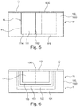
- FIG. 5 a side view of an embodiment of a blower housing 10 is shown schematically. The view is shown from the side at which the air outlet channel 111 from the first housing part 1000, which represents a block of material 100 exits.
- the nose 112 which exists between the receiving space 110 and the air outlet channel 111, visible.
- the air guide space 11 is not configured over the entire height of the material block 100.
- the air guide space 11 thus has a bottom 114.
- the air guiding space 11 in the block of material 100 is open.
- the open side of the air guiding space 11 is in the in FIG. 5 illustrated embodiment covered by a cover plate 12.
- an air inlet grille 120 is inserted, which forms the air inlet opening of the blower housing 10.
- the first housing part 1000 which constitutes a block of material 100, consists of several materials.
- a main body 101 which consists of a base material.
- the base material may be, for example, a rubber-polyurethane composite.
- a lining layer 102 is introduced from lining material.
- the lining layer 102 covers the entire boundary walls of the recess in the body 101.
- a further lining layer 103 is applied on the lining layer 102.
- the lining layer 103 thus forms the boundary walls of the receiving space 110 in the first housing part 1000.
- the lining layer 102 and the lining layer 103 may consist, for example, of polyurethane foam or melamine resin foam.
- the receiving space 110 is also covered in this embodiment by a cover plate 12, in which an air inlet grille 120 is provided. Below the cover plate 12 and in particular below the air inlet grille 120, a fan 13 is accommodated in the receiving space 110.
- the axis of rotation 130 of the fan wheel 13 lies in the vertical direction and thus extends in the height direction of the receiving space 110.
- the housing part 1000 which is formed by a block of material 100, consists of only one soundproofing material.
- a receiving space 110 is formed in the housing part 1000.
- This receiving space 110 may be formed by free cutting or by foam molding.
- the receiving space 110 does not extend over the entire height of the material block 100 in this embodiment.
- the receiving space 110 constitutes a depression in the material block 100 and has a base 114.
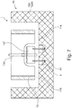
- connecting elements 5 are introduced in the soundproofing material of the housing part 1000 in the sectional view shown. In the sectional view shown, two connection elements 5 are shown. However, more than two connection elements 5 can also be provided.
- the connecting elements 5 are introduced in the embodiment shown in the bottom 114 of the receiving space 110.
- the connection elements 5 may for example consist of metal.
- the fan motor 131 and the fan wheel 13 are accommodated in the receiving space 110.
- the Fan motor 131 is in this case attached by screws 51 to the connection elements 5 and the fan 13 is mounted on the fan motor 131 so that it can rotate about the axis 130.
- the fan housing 1 can be attached to the in FIG. 7 shown open side of the receiving space 110 by a further housing part or a cover plate (both not shown) are closed, wherein in the further housing part or the cover plate then the air inlet opening of the blower 1 is formed.
- blower housing according to the invention filters and other components, such as electronic components and cables to easily integrate into the blower housing.
- guide grooves may be provided for the filters.
- the fan housing can be produced by the air guide space and in particular the receiving space in a block of material from a volume element, which preferably consists of foam or fiber material, is cut free.
- the air ducting can also be produced by foam molding.
- grooves can be easily and inexpensively integrated as guide rails for removable filter. Due to the elastic material property of the volume element, these grooves also assume a sealing function at the same time. In addition, space for electronic components and cable guides can be realized in the volume element simple and cost-effective
- both the airborne sound insulation and the structure-borne sound insulation are functionally present in the blower housing.
- foam material for the block of material has the further advantage that less expensive materials can be used, which also cause low tooling costs and can be easily mounted.
- the blower housing can also consist of a composite material or a material with locally different properties.
- a zone optimized for airborne sound can be created at the boundary layer between the airflow and the blower housing and a zone optimized for structure-borne noise for connection to the domestic appliance, which can also be referred to as a terminal.
Landscapes
- Engineering & Computer Science (AREA)
- Mechanical Engineering (AREA)
- General Engineering & Computer Science (AREA)
- Structures Of Non-Positive Displacement Pumps (AREA)
Abstract
Description
- Die vorliegende Erfindung betrifft ein Gebläsegehäuse und ein Gebläse für ein Haushaltsgerät mit einem Gebläsegehäuse.
- Bei Gebläsen, die beispielsweise in Haushaltsgeräten eingesetzt werden, und die insbesondere Radialgebläse darstellen, wird das Lüfterrad oder werden die Lüfterräder in einem Gebläsegehäuse aufgenommen. Das Gebläsegehäuse dient zur Luftführung von einer Absaugöffnung zu einer Auslassöffnung.
- In der
DE 10 2007 021 318 A1 ist ein solches Gebläsegehäuse offenbart. Insbesondere werden in dieser Druckschrift ein Dunstabzugsgehäuse und eine Dunstabzugshaube offenbart. Das Dunstabzugsgehäuse ist ausgebildet, um wenigstens ein Gebläsegehäuse und wenigstens ein vom Gebläsegehäuse umschlossenes Lüfterrad, insbesondere eines Radiallüfters, aufzunehmen. Das Dunstabzugsgehäuse weist zudem eine Absaugöffnung zur Aufnahme der Dämpfe von einer Kochstelle auf. An einer Seite des Gebläsegehäuses weist das Gebläsegehäuse einen Luftauslass beziehungsweise einen Luftstutzen auf. Das Gebläsegehäuse stellt ein Spiralgehäuse dar. Der Luftauslass kann hierbei an der Oberseite des Gebläsegehäuses angeordnet sein. Je nach Ausführung des Gebläses und der Lage des Gebläses kann der Luftauslass aber auch seitlich an dem Gebläsegehäuse liegen. - Diese bekannten Gebläsegehäuse werden in der Regel aus Blech-oder Kunststoffmaterial, das schallhart ist, hergestellt.
- Diese Art der Gebläsegehäuse weist eine Reihe von Nachteilen auf. Insbesondere kann das Blech oder Kunststoffmaterial lediglich die Funktionen der Luftführung übernehmen. Da aber bei dem Betrieb des Gebläses Geräusche, wie beispielsweise Luftschall oder Körperschall, entstehen, ist eine zusätzliche Akustikdämmung notwendig. Somit können Gebläsegehäuse nur mit hohen Material-und Werkzeugkosten hergestellt werden. Zudem ist die Montage, Befestigung und Abdichtung des Gebläsegehäuses aufwändig.
- Aufgabe der vorliegenden Erfindung ist es daher eine Lösung zu schaffen, mittels derer bei einfachem Aufbau des Gebläsegehäuses dieses gleichzeitig zur Luftführung und zur Geräuschreduzierung dienen kann.
- Der Erfindung liegt die Erkenntnis zu Grunde, dass diese Aufgabe gelöst werden kann, indem der Luftführungsraum des Gebläsegehäuses zumindest teilweise in einem Schallschutzmaterial gebildet wird.
- Gemäß einem ersten Aspekt wird die Aufgabe gelöst durch ein Gebläsegehäuse für ein Gebläse, wobei das Gebläsegehäuse einen Aufnahmeraum für mindestens ein Lüfterrad des Gebläses und einen sich an den Aufnahmeraum anschließenden Luftauslasskanal aufweist. Das Gebläsegehäuse ist dadurch gekennzeichnet, dass das Gebläsegehäuse ein Gehäuseteil aufweist, das zumindest bereichsweise aus Schallschutzmaterial besteht und in dem Gehäuseteil zumindest der Aufnahmeraum zumindest teilweise durch Schallschutzmaterial gebildet ist.
- Das Gebläsegehäuse weist einen Aufnahmeraum für mindestens ein Lüfterrad auf. Der Aufnahmeraum weist vorzugsweise einen runden, ovalen oder spiralförmigen Querschnitt auf. Das Lüfterrad wird in dem Aufnahmeraum so angeordnet, dass eine Wand des Aufnahmeraumes den Umfang des Lüfterrades weitestgehend umgibt. In dieser Wand des Aufnahmeraumes ist eine Luftauslassöffnung eingebracht, über die die Luft aus dem Aufnahmeraum in einen Luftauslasskanal strömen kann. Der Luftauslasskanal schließt sich dabei vorzugsweise tangential oder radial an den Querschnitt des Aufnahmeraumes an. Der Aufnahmeraum und der Luftauslasskanal werden gemeinsam als Luftführungsraum des Gebläsegehäuses bezeichnet.
- Besonders bevorzugt bildet das Gebläsegehäuse ein sogenanntes Spiralgehäuse. In axialer Richtung des Lüfterrades ist der Aufnahmeraum vorzugsweise durch ein oder mehrere weitere Gehäuseteile des Gebläsegehäuses abgedeckt. Diese weiteren Gehäuseteile können einen Aufbau entsprechend dem ersten Gehäuseteil aufweisen oder beispielsweise als Deckplatte ausgeführt sein. In einem dieser weiteren Gehäuseteile kann die Lufteinlassöffnung für das Gebläse vorgesehen sein und kann beispielsweise durch ein Gitter abgedeckt sein. Somit strömt Luft in das Gebläse in axialer Richtung des Lüfterrades ein und wird in radialer Richtung von dem Aufnahmeraum über die Luftauslassöffnung in den Luftauslasskanal abgegeben. Das Gebläse, das ein erfindungsgemäßes Gebläsegehäuse aufweist, ist daher vorzugsweise einen Radialgebläse.
- Das Gebläsegehäuse ist dadurch gekennzeichnet, dass das Gebläsegehäuse ein Gehäuseteil aufweist, das zumindest bereichsweise aus Schallschutzmaterial besteht und in dem Gerätegehäuse zumindest der Aufnahmeraum zumindest teilweise durch Schallschutzmaterial gebildet ist.
- Das Gehäuseteil kann einen Materialblock oder Formkörper darstellen. Das Gehäuseteil besteht zumindest bereichsweise aus Schallschutzmaterial.
- Als Schallschutzmaterial wird erfindungsgemäß ein Material verstanden, das schalldämpfend und/oder schalldämmend ist. Als Schalldämpfung oder Schallabsorption wird insbesondere eine Behinderung der Schallausbreitung bezeichnet. Insbesondere erfolgt die Schalldämpfung durch Behinderung der Schallausbreitung durch Absorption von Luftschall. Als Schalldämmung wird insbesondere die Behinderung der Schallausbreitung von Luftschall oder Körperschall in angrenzende Räume durch Schallreflexion des sich ausbreitenden Schalls bezeichnet. Das Schallschutzmaterial kann insbesondere ein schallweiches Material darstellen.
- Das Schallschutzmaterial kann daher ein poröses, elastisches und/oder faserförmiges Material darstellen. Durch diese Materialien wird zusätzlich zu der reinen Schalldämpfung und oder Schalldämmung auch eine Schwingung des Gehäuseteils bezüglich weiterer Teile des Gerätegehäuses oder des Haushaltsgerätes verhindert und damit ein weiterer Schallschutz geliefert. Besonders bevorzugt wird ein Schallschutzmaterial verwendet, das Schall in Frequenzen von 50Hz bis 10.000Hz absorbieren und/oder dämmen kann.
- Das Gehäuseteil kann vollständig aus Schallschutzmaterial bestehen. Es liegt aber auch im Rahmen der Erfindung, dass in oder an dem Schallschutzmaterial Elemente aus einem formstabilen Material vorgesehen sind, das keine Schalldämpfung- oder Schalldämmungsfunktionen aufweist. Beispielsweise können solche Elemente aus Metall bestehen und zur Lagerung des Lüfterrades oder des Lüftermotors dienen. Vorzugsweise ist das Lüfterrad indirekt über den Lüftermotor an dem Gebläsegehäuse gelagert.
- Für das bessere Verständnis werden im Folgenden die Abmessungen des Gebläsegehäuses oder des Gebläses, die beim fertiggestellten Gebläse, das heißt bei dem Gebläse, bei dem der Lüfter in das Gebläsegehäuse eingebracht ist, in der Richtung der Drehachse des Lüfterrades liegen, als Höhe bezeichnet. Zudem beziehen sich Angaben, wie oben und unten auf ein Gebläse, bei dem die Drehachse des Lüfterrades, die auch als Drehachse des Gebläses bezeichnet wird, in der Vertikalen liegt. Angaben, wie axial und radial beziehen sich ebenfalls auf die Drehachse des Lüfterrades.
- Der Aufnahmeraum ist zumindest teilweise in dem Schallschutzmaterial gebildet. Insbesondere ist zumindest die Wand des Aufnahmeraumes, die den Umfang des Lüfterrades des Gebläses umgibt, in dem Schallschutzmaterial gebildet. Zusätzlich kann auch eine der in axialer Richtung des Lüfterrades liegenden Wände des Aufnahmeraumes in dem Schallschutzmaterial gebildet sein.
- Indem das Gehäuseteil zumindest bereichsweise aus Schallschutzmaterial besteht und der Aufnahmeraum zumindest teilweise in dem Schallschutzmaterial gebildet ist, kann eine Reihe von Vorteilen erzielt werden. Insbesondere kann durch das Gebläsegehäuse selber eine Schalldämpfung und / oder Schalldämmung erfolgen. Zudem ist die Herstellung des Gebläses durch das Ausbilden zumindest des Aufnahmeraumes in dem Schallschutzmaterial vereinfacht. Insbesondere ist im Gegensatz zu einem Gebläsegehäuse nach dem Stand der Technik kein aufwändiges Ausrichten des Gebläsegehäuses zu einer zusätzlichen Akustikdämmung notwendig.
- Gemäß einer Ausführungsform stellt das Gehäuseteil einen Materialblock dar, der zumindest teilweise aus Schallschutzmaterial besteht. Vorzugsweise ist zumindest ein Teil des Aufnahmeraumes durch Materialabtrag in dem Materialblock erzeugt.
- Als Materialblock wird erfindungsgemäß ein Körper, der zumindest bereichsweise aus mindestens einem Schallschutzmaterial besteht und in dem zumindest ein Teil des Aufnahmeraums für das Lüfterrad des Gebläses gebildet ist, verstanden. Der Materialblock bezeichnet somit den bearbeiteten Körper. Vor dem Einbringen des Aufnahmeraumes, das heißt vor dem Bearbeiten, kann der Körper auch als Volumenelement, Massivkörper oder Vollkörper bezeichnet werden.
- Das Volumenelement kann beispielsweise eine Quaderform aufweisen. Auch der Materialblock kann eine Quaderform aufweisen. Alternativ ist es aber auch möglich, dass der Materialblock eine äußere Form aufweist, die der Form des darin gebildeten Luftführungsraumes entspricht. Eine solche Form kann durch Bearbeitung der Außenseite des Volumenelementes erzeugt werden.
- Gemäß einer Ausführungsform ist zumindest ein Teil des Aufnahmeraumes durch Materialabtrag in dem Materialblock erzeugt. Das Einbringen zumindest eines Teils des Aufnahmeraumes und gegebenenfalls des Luftauslasskanals durch Materialabtrag in ein Volumenelement wird auch als Negativverfahren bezeichnet. Insbesondere kann aus einem Volumenelement der Teil des Aufnahmeraumes, der in dem Materialblock gebildet werden soll, herausgeschnitten werden. Das Herausschneiden kann auch als Freischneiden bezeichnet werden. Der herausgeschnittene Teil weist vorzugsweise eine Zylinderform oder Spiralform auf, so dass in den so geschaffenen Teil des Aufnahmeraumes das Lüfterrad eingebracht werden kann und zumindest der Umfang des Lüfterrades von dem Material des Materialblockes umgeben ist. Auch der Luftauslasskanal, der bei der Ausführungsform des Gehäuseteils als Materialblock vorzugsweise in dem Materialblock ausgebildet ist, kann durch ein Negativverfahren in ein Volumenelement eingebracht werden. Vorzugsweise werden der Aufnahmeraum und der Luftauslasskanal hierbei in einem Verfahrensschritt in das Volumenelement eingebracht, insbesondere aus diesem ausgeschnitten.
- Indem zumindest ein Teil des Aufnahmeraumes in den Materialblock durch ein Verfahren mit Materialabtrag von einem Volumenelement eingebracht wird, ist der Werkzeugaufwand zur Herstellung des Gebläsegehäuses und damit dessen Herstellung weiter vereinfacht. Zudem kann bei Verwendung eines Negativverfahrens das Material des Materialblockes außer Schaumstoff beispielsweise ein Fasermaterial, gummiartiges Material oder ein poröses Material sein oder ein solches Material aufweisen. Diese Materialien können auf einfache Weise geschnitten werden.
- Gemäß einer weiteren Ausführungsform ist das Gehäuseteil durch Formen von Schallschutzmaterial um zumindest den Teil des Aufnahmeraumes, der durch das Schallschutzmittel gebildet ist, erzeugt. Das Formen des Schallschutzmaterials um zumindest einen Teil des Aufnahmeraumes wird auch als Positivverfahren bezeichnet. Insbesondere kann das Positivverfahren ein Formschäumen sein. Hierzu kann beispielsweise eine Matrize oder andere Grundform verwendet werden, die der Form des Teiles des Aufnahmeraumes und gegebenenfalls eines Teiles des Luftauslasskanals der in dem Schallschutzmaterial liegen soll, entspricht und diese Matrize kann teilweise eingeschäumt werden. Das durch Formen von Schallschutzmaterial gebildete Gehäuseteil kann einen Formkörper oder einen Materialblock darstellen. Der Materialblock kann beispielsweise eine Quaderform aufweisen.
- Auch bei der Verwendung eines Positivverfahrens ist die Herstellung des Gebläsegehäuses vereinfacht und dennoch ein Schallschutz gegeben. Zudem kann bei einem solchen Positivverfahren die Wandstärke des Gehäuseteils zumindest in dem Bereich des Aufnahmebereiches gezielt eingestellt werden. Somit kann ein ausreichender Schallschutz gewährt werden.
- Gemäß einer Ausführungsform weist das Gehäuseteil mindestens zwei Schichten auf, das heißt, dass das Gehäuseteil einen mehrschichtigen Körper darstellt. Mindestens eine der Schichten besteht vorzugsweise aus Schallschutzmaterial. Es können aber auch alle Schichten aus Schallschutzmaterial bestehen. Es liegt auch im Rahmen der Erfindung, das zumindest eine Schicht des Gehäuseteils aus einem Material besteht, das keine gesonderte Schallschutzeigenschaft aufweist. Die Schichten des Schallschutzmaterials können über deren Flächenerstreckung jeweils eine konstante Dicke aufweisen. Es liegt aber auch im Rahmen der Erfindung, dass die Schichten über deren jeweilige Flächenerstreckung unterschiedliche Dicken aufweisen. Die Schichten des Schallschutzmaterials können ebene Schichten sein. Es liegt allerdings auch im Rahmen der Erfindung, dass die Schichten jeweils eine von der Ebene abweichende Form aufweisen. In diesem Fall kann die Form der Schichten jeweils der Form des Aufnahmeraumes und gegebenenfalls des Luftauslasskanals entsprechen. Diese Ausführungsform kann besonders einfach bei der Herstellung des Gehäuseteils, der durch Positivverfahren, das heißt durch Materialauftrag erzeugt werden. Bei der Herstellung des Gehäuseteils durch ein Negativverfahren, kann der mehrschichtige Aufbau durch Beschichten einer Aussparung oder Vertiefung, die in den Materialblock eingebracht ist, oder durch Einlegen einer weiteren Schicht in dieser Aussparung oder Vertiefung erzeugt werden.
- Indem das Gehäuseteil einen mehrschichtigen Körper darstellt, können unterschiedliche Materialien in dem Gehäuseteil verwendet werden, die sich bezüglich ihrer Eigenschaften, wie Verformungsfestigkeit, Volumengewicht, Schalldämpfung und/oder Schalldämmung, unterscheiden. Somit kann ein Gebläsegehäuse erzeugt werden, das in den einzelnen Bereichen die gewünschten Eigenschaften aufweist.
- Gemäß einer Ausführungsform weist das Gehäuseteil einen Grundkörper auf und der Grundkörper weist an zumindest einem Teil des Aufnahmeraumes mindestens eine Auskleidungsschicht auf. Die Auskleidungsschicht ist bei dieser Ausführungsform vorzugsweise eine Schallschutzmaterialschicht. Bei dieser Ausführungsform kann der Grundkörper beispielsweise aus einem Material bestehen, das auf Körperschallreduktion, insbesondere Absorption, optimiert ist und die Auskleidungsschicht in dem Aufnahmeraum aus einem Material bestehen, das auf Luftschallreduktion, insbesondere Absorption, optimiert ist. Hierdurch kann zum einen der durch das Betreiben des Gebläses, insbesondere durch das Lüfterrad erzeugte Luftschall und zum anderen der durch die Anbindung an ein Haushaltsgerät, in dem das Gebläse aufgenommen ist, entstehende Körperschall absorbiert werden. Zudem kann das Gebläse zuverlässig an dem Haushaltsgerät befestigt werden, indem der Grundkörper zumindest bereichsweise aus einem Material mit hoher mechanischer Belastbarkeit, beispielsweise Gummi besteht.
- Gemäß einer Ausführungsform ist in dem Gehäuseteil mindestens eine Führung für ein Filterelement eingebracht. Die Führung ist dabei vorzugsweise in dem Schallschutzmaterial des Gehäuseteils eingebracht. Die Führung kann beispielsweise als Nut ausgestaltet sein, die als Führungsschiene zum Einschieben eines flächigen Filterelementes dient. Wird das Gehäuseteil durch ein Positivverfahren hergestellt, kann die Nut durch Umschäumen einer entsprechend geformten Matrize erzeugt werden. Alternativ kann die Nut auch in ein Gehäuseteil, das durch ein Positivverfahren hergestellt wurde, durch Schneiden eingebracht werden. Wird das Gehäuseteil durch ein Negativverfahren hergestellt, so kann die Nut bei dem Ausschneiden des Luftauslasskanals ebenfalls durch Schneiden erzeugt werden. Vorzugsweise ist die Führung im Bereich des Luftauslasskanals eingebracht. Besonders bevorzugt kann die Führung am Ende des Luftauslasskanals liegen und sich von diesem nach außen in das den Luftauslasskanal umgebenden Schallschutzmaterial erstrecken. Diese Führung kann auf einfache Weise in das Material des Gehäuseteils eingebracht werden. Die Ausführungsform, bei der die Führung des Filterelementes in dem Gehäuseteil und insbesondere in dem Schallschutzmaterial gebildet ist, ist von Vorteil, da zum einen eine separate Filterhalterung entfallen kann. Zum anderen kann das Schallschutzmaterial ein elastisches Material darstellen. Hierdurch wird zum einen der Halt des Filterelementes verbessert und gleichzeitig kann durch das Schallschutzmaterial in dem Bereich der Führung eine Dichtfunktion übernommen werden. Hierdurch kann auch das Entstehen von Pfeifgeräuschen verhindert werden.
- Gemäß einer weiteren Ausführungsform ist in dem Gehäuseteil zumindest ein Ausschnitt für mindestens ein Elektronikbauteil vorgesehen. Der mindestens eine Ausschnitt ist dabei vorzugsweise in dem Schallschutzmaterial des Gehäuseteils eingebracht. Der mindestens eine Ausschnitt kann durch Freischneiden in ein Volumenelement eingebracht werden. Alternativ kann der Ausschnitt durch Formschäumen hergestellt werden. Indem der Ausschnitt für mindestens ein Elektronikbauteil in dem Gehäuseteil vorgesehen ist, ist insbesondere die Montage des Gebläses vereinfacht. Insbesondere ist ein gesondertes Ausrichten des mindestens einen Elektronikbauteils zu dem Lüfterrad und insbesondere zu dem Lüftermotor über den das Lüfterrad angetrieben wird, nicht erforderlich. In einer weiteren bevorzugten Ausführungsform ist in dem Gehäuseteil mindestens einen Nut für mindestens ein Kabel eingebracht. Auch hierdurch wird die Montage des Gebläses weiter vereinfacht und zudem kann auf einfache Weise ein Schnittschutz für das mindestens eine Kabel geschaffen werden.
- Gemäß einer weiteren Ausführungsform ist in dem Gehäuseteil mindestens ein Anbindungselement integriert. Das mindestens eine Anbindungselement ist dabei vorzugsweise in dem Schallschutzmaterial des Gehäuseteils integriert. Als Anbindungselement wird insbesondere ein Element bezeichnet, mittels dessen das Gehäuseteil an einem weiteren Gehäuseteil oder an einem Gerät, insbesondere Haushaltsgerät, in dem das Gebläse betrieben wird, befestigt werden kann. Zudem wird als Anbindungselement auch ein Element bezeichnet, über das der Lüftermotor an dem Gehäuseteil befestigt werden kann. Das Anbindungselement kann in dem Gehäuseteil eingesetzt oder durch das Material des Gehäuseteils umschäumt sein. Das Anbindungselement kann beispielsweise aus Gummi oder Metall bestehen. Hierdurch wird sichergestellt, dass dieses mechanisch belastbar ist. Zudem weist das Anbindungselement vorzugsweise eine Schalldämpfungsfunktion für tiefe Frequenzen auf. Das Anbindungselement kann beispielsweise eine Schrauböffnung aufweisen.
- Gemäß einer weiteren Ausführungsform weißt das Gehäuse mindestens ein weiteres Gehäuseteil auf, das den Teil des Aufnahmeraumes, der durch das Schallschutzmaterial gebildet ist, an zumindest einer Seite abschließt. Das weitere Gehäuseteil kann hierbei beispielsweise eine Deckplatte darstellen. Die Deckplatte kann den Aufnahmeraum in axialer Richtung des Lüfterrades abschließen. Erfindungsgemäß können auch zwei Deckplatten vorgesehen sein, die den Aufnahmeraum in axialer Richtung des Lüfterrades an zwei Seiten abschließen. Die Deckplatte oder die Deckplatten sind mit dem ersten Gehäuseteil, in dem ein Teil des Aufnahmeraumes durch Schallstoffmaterial gebildet ist, verbunden. Die Deckplatte kann eine ebene Platte darstellen und beispielsweise aus Blech bestehen. In der Deckplatte ist vorzugsweise eine Lufteinlassöffnung für das Gebläse vorgesehen. Diese kann durch ein Gitter abgedeckt sein. Bei der Ausführungsform, bei der der Aufnahmeraum an einer Seite durch eine Deckplatte abgedeckt ist, stellt der Teil des Aufnahmeraumes, der in dem Schallschutzmaterial gebildet ist, eine Vertiefung in einer Seite des ersten Gehäuseteils und insbesondere in dem Schallschutzmaterial dar. Bei der Ausführungsform, bei der der Aufnahmeraum an zwei Seiten jeweils durch eine Deckplatte abgeschlossen ist, stellt der Teil des Aufnahmeraumes, der im ersten Gehäuseteil und insbesondere in dem Schallschutzmaterial vorgesehen ist, eine Durchlassöffnung zwischen zwei gegenüberliegenden Seiten des ersten Gehäuseteils dar.
- Es liegt aber auch im Rahmen der vorliegenden Erfindung, dass das weitere Gehäuseteil einen Aufbau aufweist, der dem Aufbau des ersten Gehäuseteils entspricht. Insbesondere kann in dem weiteren Gehäuseteil ein weiterer Teil des Aufnahmeraumes für das Lüfterrad in einem Schallschutzmaterial vorgesehen sein.
- Gemäß einer bevorzugten Ausführungsform besteht das Gehäuseteil zumindest teilweise aus Schaumstoff. Beispielsweise kann ein Polyurethan-Schaumstoff und/oder ein Melaminharz-Schaumstoff verwendet werden. Alternativ oder zusätzlich ist es auch möglich, dass das Gehäuseteil zumindest teilweise aus Polyurethan oder Gummi-Polyurethan-Material besteht. Die Verwendung von Polyurethan-Schaumstoff auf Polyetherbasis bringt den Vorteil mit sich, dass der Luftschall hierdurch besonders gut gedämmt werden kann. Das Volumengewicht eines Polyurethan-Schaumstoffes auf Polyetherbasis beträgt vorzugsweise weniger als 40 kg/m3. Dieses Material ist akustisch oberhalb einer Frequenz von etwa 1000 Hz wirksam. Somit lassen sich Strömungsgeräusche mit diesem Material wirksam mindern. Besonders bevorzugt ist das Gehäuseteil daher vorzugsweise im Bereich des Teiles des Aufnahmeraums, der in dem Gehäuseteil gebildet ist, vorgesehen. Mechanisch ist ein Polyurethan-Schaumstoff auf Polyetherbasis allerdings nicht belastbar genug, um selbst tragende Strukturen zu erzeugen. Insbesondere kann der Lüftermotor und darüber das Lüfterrad des Gebläses durch dieses Material nicht in Position gehalten werden. Hierzu können in dem Aufnahmeraum dann beispielsweise ein oder mehrere Anbindungselemente vorgesehen werden, an dem das Lüfterrad insbesondere über den Lüftermotor des Gebläses gelagert wird. Alternativ kann das Lüfterrad und über den Lüftermotor des Gebläses auch an einer Deckplatte befestigt werden, die mit dem Gehäuseteil als weiteres Gehäuseteil verbunden wird.
- Alternativ kann das Gehäuseteil einen Schaumstoff aus Melaminharz aufweisen. Dieses Material weist ein spezifisches Gewicht von etwa 9 kg/m3 auf und ist steifer, als Polyurethan-Schaumstoff auf Polyetherbasis. Dennoch ist Melaminharz nicht geeignet mechanisch belastbare Strukturen zu bauen. Dieses Material kann aber zur Auskleidung der Strömungswege, insbesondere des Aufnahmeraumes und des Luftauslasskanal verwendet werden.
- Als Material für einen Grundkörper des Gehäuseteils werden vorzugsweise deutlich schwerere und verformungsfestere Materialien mit Volumengewichten von mehr als 100 kg/m3 eingesetzt. Beispielsweise können Materialien mit einem Volumengewicht von 400 kg/m3 gewendet werden. Diese Materialien können zusammengesetzte Materialien sein und beispielsweise aus Polyurethan oder aus Gummi-Polyurethan-Kompositen hergestellt sein. Diese Materialien können bei der Herstellung auf die notwendige Druckfestigkeit und Elastizität eingestellt werden. Der wirksame Dämpfungsbereich liegt bei diesem Material unter 1000 Hz durch die Kombination von zwei Schallschutzmaterialien, beispielsweise Polyurethan und Melaminharz-Schaumstoff kann eine breitbandige Dämpfung erreicht werden.
- Aus Kostengründen kann vorzugsweise auch ein dreischichtiger Aufbau verwendet werden. Hierbei kann ein Grundkörper aus einem möglichst günstigen, steifen Material verwendet werden, das zu dem Luftführungsraum hin mit dem zuerst genannten leichten Polyurethan-Schaumstoff belegt ist und mit Einlegern aus Gummi-Polyurethan-Kompositionen versehen ist, um das Gehäuseteil schwingungstechnisch vom Rest des Gerätes, insbesondere Haushaltsgerätes, zu entkoppeln.
- Gemäß einem weiteren Aspekt betrifft die Erfindung ein Gebläse für ein Haushaltsgerät, das ein erfindungsgemäßes Gebläsegehäuse aufweist. Vorzugsweise ist das Gebläse ein Gebläse für eine Dunstabzugshaube. Das Gebläse kann aber auch in anderen Haushaltsgeräten wie beispielsweise Backöfen oder Kühlschränken oder aber beispielsweise in Wäschetrocknern oder Staubsaugern eingesetzt werden.
- Vorteile und Merkmale, die bezüglich des Gebläsegehäuses beschrieben wurden, geltensoweit anwendbar-entsprechend für das erfindungsgemäße gemäße Gebläse und umgekehrt.
- Gemäß einer Ausführungsform weist das Gebläse mindestens ein Lüfterrad auf. Das Lüfterrad des Gebläses kann entweder an dem ersten Gehäuseteil, das zumindest teilweise aus Schallschutzmaterial besteht, oder an einer Deckplatte des Gebläsegehäuses als weiterem Gehäuseteil gelagert sein. Gemäß einer Ausführungsform ist das Lüfterrad über eine Deckplatte an dem ersten Gehäuseteil gelagert und ragt in den Aufnahmeraum, der zumindest teilweise aus Schallschutzmaterial besteht, hinein. Hierbei kann das Lüfterrad indirekt an der Deckplatte gelagert sein. Insbesondere kann der Lüftermotor an der Deckplatte befestigt sein und das Lüfterrad ist mit dem Lüftermotor zur Rotation verbunden.
- Das erfindungsgemäße Gebläse stellt vorzugsweise ein Radialgebläse dar.
- Insbesondere kann das erfindungsgemäße Gebläse ein Radialgebläse mit vorwärtsgekrümmtem Radiallüfterrad sein, bei dem für den Druckaufbau ein spiralförmiges Gehäuse zwingend notwendig ist.
- Die vorliegende Erfindung wird im Folgenden erneut unter Bezugnahme auf die beiliegenden Zeichnungen genauer beschrieben. Es zeigen:
-
Figur 1 : eine Ausführungsform eines Gehäuseteils eines erfindungsgemäßen Gebläsegehäuses; -
Figur 2 : eine zweite Ausführungsform eines Gehäuseteils eines erfindungsgemäßen Gebläsegehäuses; -
Figur 3 : eine dritte Ausführungsform eines Gehäuseteils eines erfindungsgemäßen Gebläsegehäuses; -
Figur 4 : eine vierte Ausführungsform eines Gehäuseteils eines erfindungsgemäßen Gebläsegehäuses; -
Figur 5 : eine schematische Seitenansicht einer Ausführungsform des erfindungsgemäßen Gebläsegehäuses; -
Figur 6 : eine schematische Schnittansicht einer Ausführungsform eines erfindungsgemäßen Gebläses; und -
Figur 7 : eine schematische Schnittansicht einer weiteren Ausführungsform eines erfindungsgemäßen Gebläses. - In
Figur 1 ist eine Ausführungsform eines Gehäuseteils 1000 eines erfindungsgemäßen Gebläsegehäuses 10 gezeigt. In der dargestellten Ausführungsform wird das Gehäuseteil 1000 durch einen Materialblock 100 gebildet. Der Materialblock 100 weist in der dargestellten Ausführungsform eine Quaderform auf. Das Gehäuseteil 1000 und damit der Materialblock 100 können bei dieser Ausführungsform beispielsweise aus Polyurethan-Schaumstoff bestehen. In dem Materialblock 100 sind ein Aufnahmeraum 110 sowie ein Luftauslasskanal 111 eines Luftführungsraumes 11 ausgebildet. Der Luftführungsraum 11 kann durch Freischneiden aus einem Volumenelement oder durch Formschäumen hergestellt worden sein. Der Aufnahmeraum 110 weist einen runden Querschnitt auf, dessen Begrenzungswand den Teil einer Spirale bildet. In den Aufnahmeraum 110 kann das Lüfterrad und der Lüftermotor (nicht dargestellt) des Gebläses aufgenommen werden. An der Begrenzungswand des Aufnahmeraumes 110 ist eine Luftauslassöffnung ausgebildet, über die der Lüftungsraum 11 in den Luftauslasskanal 111 übergeht. Der Luftauslasskanal 111 erstreckt sich von dem Aufnahmeraum 110 bis zu einer Seitenwand des Materialblockes 100. Zwischen dem Aufnahmeraum 110 und der Seitenwand des Materialblockes 100 weitet sich der Luftauslasskanal 111 auf. In der dargestellten Ausführungsform erstreckt sich der Luftführungsraum 11 über die gesamte Höhe des Materialblockes 100. Bei der inFigur 1 gezeigten Ausführungsform des Gehäuseteils 1000 wird durch das Material des Materialblockes 100 zumindest der Luftschall, der in dem Luftführungsraum 11 entsteht, gedämpft. - In
Figur 2 ist eine weitere Ausführungsform eines Gehäuseteils 1000 gezeigt. Auch bei dieser Ausführungsform wird das Gehäuseteil 1000 durch einen Materialblock 100 gebildet. Der Materialblock kann beispielsweise aus Polyurethan-Schaumstoff bestehen. Der Luftführungsraum 11 entspricht dem Luftführungsraum 11, der in der ersten Ausführungsform gemäßFigur 1 gezeigt ist. Zusätzlich ist bei der zweiten Ausführungsform gemäßFigur 2 eine Führung 104 in dem Materialblock 100 vorgesehen. In die Führung 104 ist ein Filterelement 2 eingebracht. Das Filterelement 2 weist eine ebene, flächige Form auf und kann beispielsweise ein Geruchsfilter zum Ausfiltern von Geruchsstoffen sein. Die Führung 104 wird in der dargestellten Ausführungsform durch Nuten gebildet, die parallel zu der Seitenwand, zu der sich der Luftauslasskanal 111 erstreckt, ausgerichtet sind. Insbesondere sind die Nuten am Ende des Luftauslasskanals 111 in einem Abstand zu der Seitenwand in den Materialblock 100 eingebracht. In der dargestellten Ausführungsform ragen die Nuten von dem Luftauslasskanal 111 zu den Seiten hinaus. In den Nuten können Führungsschienen aus Metall oder einem anderen Material eingebracht sein. Das Filterelement 2 ist von oben in die Führung 104 eingebracht und bedeckt im eingebrachten Zustand das Ende des Luftauslasskanals 111. - In der
Figur 3 ist eine weitere Ausführungsform eines Gehäuseteils 1000 gezeigt. Auch bei dieser Ausführungsform wird das Gehäuseteil 1000 durch einen Materialblock 100 gebildet. Der Materialblock 100 kann beispielsweise aus Polyurethan-Schaumstoff bestehen. Diese Ausführungsform unterscheidet sich von der ersten Ausführungsform gemäßFigur 1 dadurch, dass ein Ausschnitt 105 in die Oberseite des Materialblockes 100 eingebracht ist. Der Ausschnitt 105 liegt zu dem Luftführungsraum 11 benachbart. In den Ausschnitt 105 sind Elektronikbauteile 3 eingeführt. Der Ausschnitt 105 ist über einen Nut 106 mit dem Aufnahmeraum 110 verbunden und in dieser Nut 106 ist ein Kabel 4 geführt, über das die Elektronikbauteile 3 mit dem Lüftermotor (nicht gezeigt) des Gebläses 1 verbunden werden können. - In
Figur 4 ist eine vierte Ausführungsform eines Gehäuseteils 1000 gezeigt. Auch bei dieser Ausführungsform wird das Gehäuseteil 1000 durch einen Materialblock 100 gebildet. Der Materialblock 100 kann beispielsweise aus Polyurethan-Schaumstoff bestehen. Diese Ausführungsform unterscheidet sich von der inFigur 1 gezeigten Ausführungsform in zweierlei Hinsicht. Zum einen ist an der Begrenzungswand des Aufnahmeraumes 110 und des Luftauslasskanals 111 eine Auskleidungsschicht 102 aufgebracht. Zum anderen ist in den Materialblock 101 ein Anbindungselement 5 eingebracht. Dieses Anbindungselement 5 ist zu dem Luftführungsraum 11 beanstandet angeordnet. Das Anbindungselement 5 kann beispielsweise aus Gummi bestehen und eine Würfelform aufweisen. In dem Anwendungselement 5 ist in der dargestellten Ausführungsform eine Schrauböffnung 50 gezeigt, über die das Gehäuseteil 1000 an einem weiteren Gehäuseteil (nicht gezeigt) befestigt werden kann, oder über das das Gebläsegehäuse 10 an dem Hauptgerät, insbesondere Haushaltsgerät befestigt werden kann. - In der
Figur 5 ist eine Seitenansicht einer Ausführungsform eines Gebläsegehäuses 10 schematisch gezeigt. Die Ansicht ist von der Seite aus dargestellt, an der der Luftauslasskanal 111 aus dem ersten Gehäuseteil 1000, das einen Materialblock 100 darstellt, austritt. Bei der Ansicht in den Luftauslasskanal 111 ist die Nase 112, die zwischen dem Aufnahmeraum 110 und dem Luftauslasskanal 111 besteht, sichtbar. Bei der inFigur 5 gezeigten Ausführungsform ist der Luftführungsraum 11 nicht über die gesamte Höhe des Materialblockes 100 ausgestaltet. Der Luftführungsraum 11 weist somit einen Boden 114 auf. Nach oben ist der Luftführungsraum 11 in dem Materialblock 100 offen. Die offene Seite des Luftführungsraumes 11 ist in der inFigur 5 dargestellten Ausführungsform durch eine Deckplatte 12 abgedeckt. In der Deckplatte 12 ist ein Lufteinlassgitter 120 eingebracht, das die Lufteintrittsöffnung des Gebläsegehäuses 10 bildet. - In
Figur 6 ist eine weitere Ausführungsform des erfindungsgemäßen Gebläses 1 gezeigt. Bei dieser Ausführungsform besteht das erste Gehäuseteil 1000, das einen Materialblock 100 darstellt, aus mehreren Materialien. Insbesondere ist ein Grundkörper 101 gezeigt, der aus einem Grundmaterial besteht. Das Grundmaterial kann beispielsweise ein Gummi-Polyurethan-Composite sein. In diesem Grundkörper 101 ist von einer Seite aus, in derFigur 6 von oben eine Aussparung eingebracht, in der eine Auskleidungsschicht 102 aus Auskleidungsmaterial eingebracht ist. Die Auskleidungsschicht 102 deckt die gesamten Begrenzungswände der Aussparung in dem Grundkörper 101 ab. Auf die Auskleidungsschicht 102 ist eine weitere Auskleidungsschicht 103 aufgebracht. Die Auskleidungsschicht 103 bildet somit die Begrenzungswände des Aufnahmeraumes 110 in dem ersten Gehäuseteil 1000. Die Auskleidungsschicht 102 und die Auskleidungsschicht 103 können beispielsweise aus Polyurethan-Schaum oder Melaminharz-Schaum bestehen. Nach oben ist der Aufnahmeraum 110 auch bei dieser Ausführungsform durch eine Deckplatte 12 abgedeckt, in der einen Lufteinlassgitter 120 vorgesehen ist. Unterhalb der Deckplatte 12 und insbesondere unterhalb des Lufteinlassgitters 120 ist ein Lüfterrad 13 in dem Aufnahmeraum 110 aufgenommen. Die Drehachse 130 des Lüfterrades 13 liegt in der Vertikalen und erstreckt sich somit in der Höhenrichtung des Aufnahmeraumes 110. - In der
Figur 7 ist eine weitere Ausführungsform eines erfindungsgemäßen Gebläses 1 in Schnittansicht gezeigt. Bei dieser Ausführungsform besteht das Gehäuseteil 1000, das durch einen Materialblock 100 gebildet ist, aus nur einem Schallschutzmaterial. In dem Gehäuseteil 1000 ist ein Aufnahmeraum 110 ausgebildet. Dieser Aufnahmeraum 110 kann durch Freischneiden oder durch Formschäumen gebildet sein. Der Aufnahmeraum 110 erstreckt sich bei dieser Ausführungsform nicht über die gesamte Höhe des Materialblockes 100. Somit stellt der Aufnahmeraum 110 eine Vertiefung in dem Materialblock 100 dar und weist einen Boden 114 auf. In das Schallschutzmaterial des Gehäuseteils 1000 sind Anbindungselemente 5 eingebracht. In der gezeigten Schnittansicht sind zwei Anbindungselemente 5 gezeigt. Es können aber auch mehr als zwei Anbindungselemente 5 vorgesehen sein. Die Anbindungselemente 5 sind bei der gezeigten Ausführungsform in den Boden 114 des Aufnahmeraumes 110 eingebracht. Die Anbindungselemente 5 können beispielsweise aus Metall bestehen. In dem Aufnahmeraum 110 ist der Lüfter des Gebläses 1 eingebracht. Insbesondere sind in dem Aufnahmeraum 110 der Lüftermotor 131 und das Lüfterrad 13 aufgenommen. Der Lüftermotor 131 ist hierbei über Schrauben 51 an den Anbindungselementen 5 befestigt und das Lüfterrad 13 ist an dem Lüftermotor 131 so gelagert, dass dieses sich um die Achse 130 drehen kann. Auch bei der inFigur 7 gezeigten Ausführungsform kann das Gebläsegehäuse 1 an der inFigur 7 gezeigten offenen Seite des Aufnahmeraumes 110 durch ein weiteres Gehäuseteil oder eine Deckplatte (beides nicht gezeigt) verschlossen werden, wobei in dem weiteren Gehäuseteil oder der Deckplatte dann die Lufteinlassöffnung des Gebläses 1 gebildet ist. - Mit der vorliegenden Erfindung kann eine Reihe von Vorteilen erzielt werden. Insbesondere können die Material- und Werkzeugkosten gegenüber bekannten Gebläsen reduziert werden. Zudem ist die Montage, Befestigung und Abdichtung des Gebläses bei der vorliegenden Erfindung vereinfacht. Zudem ist eine aufwändige Ausrichtung und Integration von Gehäusegeometrie und Leitgeometrie bei der vorliegenden Erfindung nicht erforderlich. Insbesondere ist zur Dämpfung des Körperschalls ein zusätzliches Bauteil zwischen einem Kunststoffgehäuse und Gerätegehäuse des Haushaltsgerätes nicht erforderlich. Auch eine zusätzliche Akustikdämmung des Luftschalls ist bei dem erfindungsgemäßen Gebläsegehäuse nicht erforderlich. Zudem ist es bei dem erfindungsgemäßen Gebläsegehäuse möglich Filter und weitere Bauteile, wie beispielsweise Elektronikbauteile und Kabel auf einfache Weise in das Gebläsegehäuse zu integrieren. Für die Filter können beispielsweise Führungsnuten vorgesehen sein. Eine zusätzliche Kabelführung, Kabelschutz, Zugentlastung und Halterungen für Kabel können ebenfalls entfallen. Erfindungsgemäß kann das Gebläsegehäuse hergestellt werden, indem der Luftführungsraum und insbesondere der Aufnahmeraum in einem Materialblock aus einem Volumenelement, das vorzugsweise aus Schaum oder Fasermaterial besteht, freigeschnitten wird. Alternativ kann der Luftführungsraum aber auch durch Formschäumen hergestellt werden.
- In das Volumenelement, das den Materialblock gebildet, können einfach und kostengünstig Nuten als Führungsschienen für entnehmbare Filter integriert werden. Aufgrund der elastischen Materialeigenschaft des Volumenelementes übernehmen diese Nuten auch gleichzeitig eine Dichtfunktion. Zudem können in dem Volumenelement einfach und kostengünstig Bauräume für Elektronikbauteile und Kabelführungen realisiert werden
- In dem erfindungsgemäßen Gebläsegehäuse ist sowohl die Luftschalldämmung als auch die Körperschalldämmung funktional in dem Gebläsegehäuse vorhanden. Insbesondere bei der Verwendung von Schaummaterial für den Materialblock wird der weitere Vorteil erzielt, dass kostengünstigere Materialien verwendet werden können, die zudem geringe Werkzeugkosten verursachen und auf einfache Weise montiert werden können. Durch das Vorsehen einer Kabelführung in dem Materialblock kann neben der eigentlichen Führung auch ein Schnittschutz für die Kabel hergestellt werden.
- Besonders bevorzugt kann das Gebläsegehäuse auch aus einem Materialverbund oder einem Material mit lokal unterschiedlichen Eigenschaften bestehen. Hierdurch kann speziell auf die unterschiedlichen Funktionen eingegangen werden. Insbesondere kann eine auf Luftschall optimierte Zone an der Grenzschicht zwischen Luftstrom und Gebläsegehäuse und eine auf Körperschall optimierte Zone zur Anbindung an das Haushaltsgerät, das auch als Endgerät bezeichnet werden kann, geschaffen werden.
-
- 1
- Gebläse
- 10
- Gebläsegehäuse
- 1000
- Gehäuseteil
- 100
- Materialblock
- 101
- Grundkörper
- 102
- Auskleidungsschicht
- 103
- Auskleidungsschicht
- 104
- Führung
- 105
- Ausschnitt
- 106
- Nut
- 11
- Luftführungsraum
- 110
- Aufnahmeraum
- 111
- Luftauslasskanal
- 112
- Nase
- 113
- Luftaustrittsöffnung
- 114
- Boden
- 12
- Deckplatte
- 120
- Lufteinlassgitter
- 13
- Lüfterrad
- 130
- Drehachse
- 131
- Lüftermotor
- 2
- Filterelement
- 3
- Elektronikbauteil
- 4
- Kabel
- 5
- Anbindungselement
- 50
- Schrauböffnung
- 51
- Schraube
Claims (13)
- Gebläsegehäuse für ein Gebläse (1) mit einem Aufnahmeraum (110) für mindestens ein Lüfterrad (13) und einem sich an den Aufnahmeraum (110) anschließenden Luftauslasskanal (111), dadurch gekennzeichnet, dass das Gebläsegehäuse (10) ein Gehäuseteil (1000) aufweist, das zumindest bereichsweise aus Schallschutzmaterial besteht und in dem Gehäuseteil (1000) zumindest der Aufnahmeraum (110) zumindest teilweise durch Schallschutzmaterial gebildet ist.
- Gebläsegehäuse nach Anspruch 1, dadurch gekennzeichnet, dass das Gehäuseteil (1000) einen Materialblock (100) darstellt, der zumindest teilweise aus Schallschutzmaterial besteht und zumindest ein Teil des Aufnahmeraumes (110) durch Materialabtrag in dem Materialblock (100) erzeugt ist.
- Gebläsegehäuse nach Anspruch 1, dadurch gekennzeichnet, dass das Gehäuseteil (1000) durch Formen von Schallschutzmaterial um zumindest den Teil des Aufnahmeraumes (110), der durch das Schallschutzmaterial gebildet ist, erzeugt ist.
- Gebläsegehäuse nach einem der Ansprüche 1 bis 3, dadurch gekennzeichnet, dass das Gehäuseteil (1000) mindestens zwei Schichten (101, 102, 103) aufweist und mindestens eine der Schichten aus Schallschutzmaterial (101, 102, 103) besteht.
- Gebläsegehäuse nach Anspruch 4, dadurch gekennzeichnet, dass das Gehäuseteil (1000) einen Grundkörper (101) aufweist und der Grundkörper (101) an zumindest einem Teil des Aufnahmeraumes (110) mindestens eine Auskleidungsschicht (102, 103) aufweist, die aus Schallschutzmaterial besteht.
- Gebläsegehäuse nach einem der Ansprüche 1 bis 5, dadurch gekennzeichnet, dass in dem Gehäuseteil (1000) mindestens eine Führung (104) für ein Filterelement (2) eingebracht ist.
- Gebläsegehäuse nach einem der Ansprüche 1 bis 6, dadurch gekennzeichnet, dass in dem Gehäuseteil (1000) mindestens ein Ausschnitt (105) für mindestens ein Elektronikbauteil (3) und vorzugsweise mindestens eine Nut (106) für mindestens ein Kabel (4) eingebracht ist.
- Gebläsegehäuse nach einem der Ansprüche 1 bis 7, dadurch gekennzeichnet, dass in Gehäuseteil (1000) mindestens ein Anbindungselement (5) integriert ist.
- Gebläsegehäuse nach einem der Ansprüche 1 bis 8, dadurch gekennzeichnet, dass das Gehäuse (10) mindestens ein weiteres Gehäuseteil (1000, 12) aufweist, das den Teil des Aufnahmeraumes (110) des ersten Gehäuseteils (1000), der durch das Schallschutzmaterial gebildet ist, an zumindest einer Seite abschließt.
- Gebläsegehäuse nach einem der Ansprüche 1 bis 9, dadurch gekennzeichnet, dass das Gehäuseteil (1000) zumindest teilweise aus Schaumstoff, insbesondere aus Polyurethan-Schaumstoff und/oder Melaminharz-Schaumstoff besteht, oder das Gehäuseteil aus Polyurethan oder Gummi-Polyurethan-Material besteht.
- Gebläse für ein Haushaltsgerät, dadurch gekennzeichnet, dass dieses Gebläse (1) ein Gebläsegehäuse (10) nach einem der Ansprüche 1 bis 10 aufweist.
- Gebläse nach Anspruch 11, dadurch gekennzeichnet, dass das Gebläse (1) mindestens ein Lüfterrad (13) aufweist, das über eine Deckplatte (12) an dem Gehäuseteil (1000) gelagert ist und in den Aufnahmebereich (110), der zumindest teilweise aus Schallschutzmaterial besteht, hineinragt.
- Gebläse nach einem der Ansprüche 11 oder 12, dadurch gekennzeichnet, dass das Gebläse (1) ein Radialgebläse darstellt.
Applications Claiming Priority (1)
| Application Number | Priority Date | Filing Date | Title |
|---|---|---|---|
| DE102017223054.1A DE102017223054A1 (de) | 2017-12-18 | 2017-12-18 | Gebläsegehäuse und Gebläse für ein Haushaltsgerät |
Publications (1)
| Publication Number | Publication Date |
|---|---|
| EP3499047A1 true EP3499047A1 (de) | 2019-06-19 |
Family
ID=64665040
Family Applications (1)
| Application Number | Title | Priority Date | Filing Date |
|---|---|---|---|
| EP18211974.3A Pending EP3499047A1 (de) | 2017-12-18 | 2018-12-12 | Gebläsegehäuse und gebläse für ein haushaltsgerät |
Country Status (2)
| Country | Link |
|---|---|
| EP (1) | EP3499047A1 (de) |
| DE (1) | DE102017223054A1 (de) |
Citations (3)
| Publication number | Priority date | Publication date | Assignee | Title |
|---|---|---|---|---|
| FR2406107A1 (fr) * | 1977-10-11 | 1979-05-11 | Vierling Charles | Forme en matiere synthetique alveolee pour caisson de ventilation |
| EP0083704A1 (de) * | 1981-12-24 | 1983-07-20 | FSL Fenster-System-Lüftung GmbH | Gebläse, insbesondere Einbaugebläse |
| DE102007021318A1 (de) | 2007-05-07 | 2008-11-13 | BSH Bosch und Siemens Hausgeräte GmbH | Dunstabzugsgehäuse und Dunstabzugshaube |
-
2017
- 2017-12-18 DE DE102017223054.1A patent/DE102017223054A1/de not_active Withdrawn
-
2018
- 2018-12-12 EP EP18211974.3A patent/EP3499047A1/de active Pending
Patent Citations (3)
| Publication number | Priority date | Publication date | Assignee | Title |
|---|---|---|---|---|
| FR2406107A1 (fr) * | 1977-10-11 | 1979-05-11 | Vierling Charles | Forme en matiere synthetique alveolee pour caisson de ventilation |
| EP0083704A1 (de) * | 1981-12-24 | 1983-07-20 | FSL Fenster-System-Lüftung GmbH | Gebläse, insbesondere Einbaugebläse |
| DE102007021318A1 (de) | 2007-05-07 | 2008-11-13 | BSH Bosch und Siemens Hausgeräte GmbH | Dunstabzugsgehäuse und Dunstabzugshaube |
Also Published As
| Publication number | Publication date |
|---|---|
| DE102017223054A1 (de) | 2019-06-19 |
Similar Documents
| Publication | Publication Date | Title |
|---|---|---|
| EP0099466B2 (de) | Schmutzsauger | |
| EP2267373B1 (de) | Externes Gebläse für Dunstabzugsvorrichtung | |
| EP2506953B1 (de) | Dunstabzugshaube | |
| DE102011008518B4 (de) | Wand für einen Luftkanal, Luftkanal und Klimaanlage | |
| EP3710756B1 (de) | Dunstabzugsvorrichtung für ein kochfeld und küchenmöbel mit dunstabzugsvorrichtung | |
| EP0702105B1 (de) | Gehäuse für ein Gebläse einem Haushaltgerät, insbesondere in einem Haushalt-Wäschetrockner | |
| EP1495885B2 (de) | Luftführungselement für ein Kraftfahrzeug | |
| WO2018028740A1 (de) | Geräuschmindernde kapsel einer gebläsemotoreinheit eines staubsaugers sowie staubsauger | |
| DE69713561T2 (de) | Küchenventilator | |
| EP3710755B1 (de) | Dunstabzugsvorrichtung für ein kochfeld und küchenmöbel mit dunstabzugsvorrichtung | |
| EP2510861A2 (de) | Motoranordnung für ein elektromotorisch angetriebenes Haushaltsgerät | |
| DE102014008379B4 (de) | Schallschutz-Einhausung | |
| DE102015100564B4 (de) | Dunstabzugshaube | |
| EP3499046A1 (de) | Gebläsegehäuse, gebläse für ein haushaltsgerät und verfahren zur herstellung eines gebläsegehäuses | |
| EP2510855A2 (de) | Motoranordnung für ein elektromotorisch angetriebenes Haushaltsgerät und Reinigungsgerät | |
| DE102017223054A1 (de) | Gebläsegehäuse und Gebläse für ein Haushaltsgerät | |
| DE102016216292A1 (de) | Schwingungsentkoppelte und schallreduzierte Aufhängung eines Motors in einem Staubsauger | |
| DE102008011012B4 (de) | Schaltschrank | |
| DE102023113404A1 (de) | Schallisolationsanordnung | |
| DE102015101039A1 (de) | Dunstabzugshaube | |
| DE102023200284B4 (de) | Geräuscharme eingebaute Hydraulikantriebseinheit | |
| EP4328496B1 (de) | In ein kochfeld baulich integrierbare dunstabzugsvorrichtung und kochfeld | |
| EP2955450B1 (de) | Dunstabzugshaube | |
| DE212019000463U1 (de) | Eine Küchendunstabzugshaube umfassend ein Trennelement für den Absaugschacht | |
| BE1030803B1 (de) | In ein Kochfeld baulich integrierbare Dunstabzugsvorrichtung und Kochfeld |
Legal Events
| Date | Code | Title | Description |
|---|---|---|---|
| PUAI | Public reference made under article 153(3) epc to a published international application that has entered the european phase |
Free format text: ORIGINAL CODE: 0009012 |
|
| STAA | Information on the status of an ep patent application or granted ep patent |
Free format text: STATUS: THE APPLICATION HAS BEEN PUBLISHED |
|
| AK | Designated contracting states |
Kind code of ref document: A1 Designated state(s): AL AT BE BG CH CY CZ DE DK EE ES FI FR GB GR HR HU IE IS IT LI LT LU LV MC MK MT NL NO PL PT RO RS SE SI SK SM TR |
|
| AX | Request for extension of the european patent |
Extension state: BA ME |
|
| STAA | Information on the status of an ep patent application or granted ep patent |
Free format text: STATUS: REQUEST FOR EXAMINATION WAS MADE |
|
| 17P | Request for examination filed |
Effective date: 20191219 |
|
| RBV | Designated contracting states (corrected) |
Designated state(s): AL AT BE BG CH CY CZ DE DK EE ES FI FR GB GR HR HU IE IS IT LI LT LU LV MC MK MT NL NO PL PT RO RS SE SI SK SM TR |
|
| STAA | Information on the status of an ep patent application or granted ep patent |
Free format text: STATUS: EXAMINATION IS IN PROGRESS |
|
| 17Q | First examination report despatched |
Effective date: 20210503 |