EP3498232A2 - Dispositiv orthopédique - Google Patents
Dispositiv orthopédique Download PDFInfo
- Publication number
- EP3498232A2 EP3498232A2 EP19150758.1A EP19150758A EP3498232A2 EP 3498232 A2 EP3498232 A2 EP 3498232A2 EP 19150758 A EP19150758 A EP 19150758A EP 3498232 A2 EP3498232 A2 EP 3498232A2
- Authority
- EP
- European Patent Office
- Prior art keywords
- knee
- joint
- ankle joint
- orthopedic
- angle
- Prior art date
- Legal status (The legal status is an assumption and is not a legal conclusion. Google has not performed a legal analysis and makes no representation as to the accuracy of the status listed.)
- Withdrawn
Links
Images






Classifications
-
- A—HUMAN NECESSITIES
- A61—MEDICAL OR VETERINARY SCIENCE; HYGIENE
- A61F—FILTERS IMPLANTABLE INTO BLOOD VESSELS; PROSTHESES; DEVICES PROVIDING PATENCY TO, OR PREVENTING COLLAPSING OF, TUBULAR STRUCTURES OF THE BODY, e.g. STENTS; ORTHOPAEDIC, NURSING OR CONTRACEPTIVE DEVICES; FOMENTATION; TREATMENT OR PROTECTION OF EYES OR EARS; BANDAGES, DRESSINGS OR ABSORBENT PADS; FIRST-AID KITS
- A61F2/00—Filters implantable into blood vessels; Prostheses, i.e. artificial substitutes or replacements for parts of the body; Appliances for connecting them with the body; Devices providing patency to, or preventing collapsing of, tubular structures of the body, e.g. stents
- A61F2/50—Prostheses not implantable in the body
- A61F2/68—Operating or control means
- A61F2/70—Operating or control means electrical
-
- A—HUMAN NECESSITIES
- A61—MEDICAL OR VETERINARY SCIENCE; HYGIENE
- A61F—FILTERS IMPLANTABLE INTO BLOOD VESSELS; PROSTHESES; DEVICES PROVIDING PATENCY TO, OR PREVENTING COLLAPSING OF, TUBULAR STRUCTURES OF THE BODY, e.g. STENTS; ORTHOPAEDIC, NURSING OR CONTRACEPTIVE DEVICES; FOMENTATION; TREATMENT OR PROTECTION OF EYES OR EARS; BANDAGES, DRESSINGS OR ABSORBENT PADS; FIRST-AID KITS
- A61F2/00—Filters implantable into blood vessels; Prostheses, i.e. artificial substitutes or replacements for parts of the body; Appliances for connecting them with the body; Devices providing patency to, or preventing collapsing of, tubular structures of the body, e.g. stents
- A61F2/50—Prostheses not implantable in the body
- A61F2/60—Artificial legs or feet or parts thereof
- A61F2/604—Joints for artificial legs
-
- A—HUMAN NECESSITIES
- A61—MEDICAL OR VETERINARY SCIENCE; HYGIENE
- A61F—FILTERS IMPLANTABLE INTO BLOOD VESSELS; PROSTHESES; DEVICES PROVIDING PATENCY TO, OR PREVENTING COLLAPSING OF, TUBULAR STRUCTURES OF THE BODY, e.g. STENTS; ORTHOPAEDIC, NURSING OR CONTRACEPTIVE DEVICES; FOMENTATION; TREATMENT OR PROTECTION OF EYES OR EARS; BANDAGES, DRESSINGS OR ABSORBENT PADS; FIRST-AID KITS
- A61F2/00—Filters implantable into blood vessels; Prostheses, i.e. artificial substitutes or replacements for parts of the body; Appliances for connecting them with the body; Devices providing patency to, or preventing collapsing of, tubular structures of the body, e.g. stents
- A61F2/50—Prostheses not implantable in the body
- A61F2/60—Artificial legs or feet or parts thereof
- A61F2/64—Knee joints
-
- A—HUMAN NECESSITIES
- A61—MEDICAL OR VETERINARY SCIENCE; HYGIENE
- A61F—FILTERS IMPLANTABLE INTO BLOOD VESSELS; PROSTHESES; DEVICES PROVIDING PATENCY TO, OR PREVENTING COLLAPSING OF, TUBULAR STRUCTURES OF THE BODY, e.g. STENTS; ORTHOPAEDIC, NURSING OR CONTRACEPTIVE DEVICES; FOMENTATION; TREATMENT OR PROTECTION OF EYES OR EARS; BANDAGES, DRESSINGS OR ABSORBENT PADS; FIRST-AID KITS
- A61F2/00—Filters implantable into blood vessels; Prostheses, i.e. artificial substitutes or replacements for parts of the body; Appliances for connecting them with the body; Devices providing patency to, or preventing collapsing of, tubular structures of the body, e.g. stents
- A61F2/50—Prostheses not implantable in the body
- A61F2/60—Artificial legs or feet or parts thereof
- A61F2/66—Feet; Ankle joints
- A61F2/6607—Ankle joints
-
- A—HUMAN NECESSITIES
- A61—MEDICAL OR VETERINARY SCIENCE; HYGIENE
- A61F—FILTERS IMPLANTABLE INTO BLOOD VESSELS; PROSTHESES; DEVICES PROVIDING PATENCY TO, OR PREVENTING COLLAPSING OF, TUBULAR STRUCTURES OF THE BODY, e.g. STENTS; ORTHOPAEDIC, NURSING OR CONTRACEPTIVE DEVICES; FOMENTATION; TREATMENT OR PROTECTION OF EYES OR EARS; BANDAGES, DRESSINGS OR ABSORBENT PADS; FIRST-AID KITS
- A61F2/00—Filters implantable into blood vessels; Prostheses, i.e. artificial substitutes or replacements for parts of the body; Appliances for connecting them with the body; Devices providing patency to, or preventing collapsing of, tubular structures of the body, e.g. stents
- A61F2/50—Prostheses not implantable in the body
- A61F2/68—Operating or control means
- A61F2/74—Operating or control means fluid, i.e. hydraulic or pneumatic
- A61F2/748—Valve systems
-
- A—HUMAN NECESSITIES
- A61—MEDICAL OR VETERINARY SCIENCE; HYGIENE
- A61F—FILTERS IMPLANTABLE INTO BLOOD VESSELS; PROSTHESES; DEVICES PROVIDING PATENCY TO, OR PREVENTING COLLAPSING OF, TUBULAR STRUCTURES OF THE BODY, e.g. STENTS; ORTHOPAEDIC, NURSING OR CONTRACEPTIVE DEVICES; FOMENTATION; TREATMENT OR PROTECTION OF EYES OR EARS; BANDAGES, DRESSINGS OR ABSORBENT PADS; FIRST-AID KITS
- A61F5/00—Orthopaedic methods or devices for non-surgical treatment of bones or joints; Nursing devices ; Anti-rape devices
- A61F5/01—Orthopaedic devices, e.g. long-term immobilising or pressure directing devices for treating broken or deformed bones such as splints, casts or braces
- A61F5/0102—Orthopaedic devices, e.g. long-term immobilising or pressure directing devices for treating broken or deformed bones such as splints, casts or braces specially adapted for correcting deformities of the limbs or for supporting them; Ortheses, e.g. with articulations
- A61F5/0104—Orthopaedic devices, e.g. long-term immobilising or pressure directing devices for treating broken or deformed bones such as splints, casts or braces specially adapted for correcting deformities of the limbs or for supporting them; Ortheses, e.g. with articulations without articulation
- A61F5/0106—Orthopaedic devices, e.g. long-term immobilising or pressure directing devices for treating broken or deformed bones such as splints, casts or braces specially adapted for correcting deformities of the limbs or for supporting them; Ortheses, e.g. with articulations without articulation for the knees
-
- A—HUMAN NECESSITIES
- A61—MEDICAL OR VETERINARY SCIENCE; HYGIENE
- A61F—FILTERS IMPLANTABLE INTO BLOOD VESSELS; PROSTHESES; DEVICES PROVIDING PATENCY TO, OR PREVENTING COLLAPSING OF, TUBULAR STRUCTURES OF THE BODY, e.g. STENTS; ORTHOPAEDIC, NURSING OR CONTRACEPTIVE DEVICES; FOMENTATION; TREATMENT OR PROTECTION OF EYES OR EARS; BANDAGES, DRESSINGS OR ABSORBENT PADS; FIRST-AID KITS
- A61F5/00—Orthopaedic methods or devices for non-surgical treatment of bones or joints; Nursing devices ; Anti-rape devices
- A61F5/01—Orthopaedic devices, e.g. long-term immobilising or pressure directing devices for treating broken or deformed bones such as splints, casts or braces
- A61F5/0102—Orthopaedic devices, e.g. long-term immobilising or pressure directing devices for treating broken or deformed bones such as splints, casts or braces specially adapted for correcting deformities of the limbs or for supporting them; Ortheses, e.g. with articulations
- A61F5/0104—Orthopaedic devices, e.g. long-term immobilising or pressure directing devices for treating broken or deformed bones such as splints, casts or braces specially adapted for correcting deformities of the limbs or for supporting them; Ortheses, e.g. with articulations without articulation
- A61F5/0111—Orthopaedic devices, e.g. long-term immobilising or pressure directing devices for treating broken or deformed bones such as splints, casts or braces specially adapted for correcting deformities of the limbs or for supporting them; Ortheses, e.g. with articulations without articulation for the feet or ankles
-
- A—HUMAN NECESSITIES
- A61—MEDICAL OR VETERINARY SCIENCE; HYGIENE
- A61F—FILTERS IMPLANTABLE INTO BLOOD VESSELS; PROSTHESES; DEVICES PROVIDING PATENCY TO, OR PREVENTING COLLAPSING OF, TUBULAR STRUCTURES OF THE BODY, e.g. STENTS; ORTHOPAEDIC, NURSING OR CONTRACEPTIVE DEVICES; FOMENTATION; TREATMENT OR PROTECTION OF EYES OR EARS; BANDAGES, DRESSINGS OR ABSORBENT PADS; FIRST-AID KITS
- A61F5/00—Orthopaedic methods or devices for non-surgical treatment of bones or joints; Nursing devices ; Anti-rape devices
- A61F5/01—Orthopaedic devices, e.g. long-term immobilising or pressure directing devices for treating broken or deformed bones such as splints, casts or braces
- A61F5/0102—Orthopaedic devices, e.g. long-term immobilising or pressure directing devices for treating broken or deformed bones such as splints, casts or braces specially adapted for correcting deformities of the limbs or for supporting them; Ortheses, e.g. with articulations
- A61F5/0123—Orthopaedic devices, e.g. long-term immobilising or pressure directing devices for treating broken or deformed bones such as splints, casts or braces specially adapted for correcting deformities of the limbs or for supporting them; Ortheses, e.g. with articulations for the knees
- A61F5/0125—Orthopaedic devices, e.g. long-term immobilising or pressure directing devices for treating broken or deformed bones such as splints, casts or braces specially adapted for correcting deformities of the limbs or for supporting them; Ortheses, e.g. with articulations for the knees the device articulating around a single pivot-point
-
- A—HUMAN NECESSITIES
- A61—MEDICAL OR VETERINARY SCIENCE; HYGIENE
- A61F—FILTERS IMPLANTABLE INTO BLOOD VESSELS; PROSTHESES; DEVICES PROVIDING PATENCY TO, OR PREVENTING COLLAPSING OF, TUBULAR STRUCTURES OF THE BODY, e.g. STENTS; ORTHOPAEDIC, NURSING OR CONTRACEPTIVE DEVICES; FOMENTATION; TREATMENT OR PROTECTION OF EYES OR EARS; BANDAGES, DRESSINGS OR ABSORBENT PADS; FIRST-AID KITS
- A61F5/00—Orthopaedic methods or devices for non-surgical treatment of bones or joints; Nursing devices ; Anti-rape devices
- A61F5/01—Orthopaedic devices, e.g. long-term immobilising or pressure directing devices for treating broken or deformed bones such as splints, casts or braces
- A61F5/0102—Orthopaedic devices, e.g. long-term immobilising or pressure directing devices for treating broken or deformed bones such as splints, casts or braces specially adapted for correcting deformities of the limbs or for supporting them; Ortheses, e.g. with articulations
- A61F5/0127—Orthopaedic devices, e.g. long-term immobilising or pressure directing devices for treating broken or deformed bones such as splints, casts or braces specially adapted for correcting deformities of the limbs or for supporting them; Ortheses, e.g. with articulations for the feet
-
- A—HUMAN NECESSITIES
- A61—MEDICAL OR VETERINARY SCIENCE; HYGIENE
- A61F—FILTERS IMPLANTABLE INTO BLOOD VESSELS; PROSTHESES; DEVICES PROVIDING PATENCY TO, OR PREVENTING COLLAPSING OF, TUBULAR STRUCTURES OF THE BODY, e.g. STENTS; ORTHOPAEDIC, NURSING OR CONTRACEPTIVE DEVICES; FOMENTATION; TREATMENT OR PROTECTION OF EYES OR EARS; BANDAGES, DRESSINGS OR ABSORBENT PADS; FIRST-AID KITS
- A61F2/00—Filters implantable into blood vessels; Prostheses, i.e. artificial substitutes or replacements for parts of the body; Appliances for connecting them with the body; Devices providing patency to, or preventing collapsing of, tubular structures of the body, e.g. stents
- A61F2/50—Prostheses not implantable in the body
- A61F2002/5003—Prostheses not implantable in the body having damping means, e.g. shock absorbers
- A61F2002/5006—Dampers, e.g. hydraulic damper
-
- A—HUMAN NECESSITIES
- A61—MEDICAL OR VETERINARY SCIENCE; HYGIENE
- A61F—FILTERS IMPLANTABLE INTO BLOOD VESSELS; PROSTHESES; DEVICES PROVIDING PATENCY TO, OR PREVENTING COLLAPSING OF, TUBULAR STRUCTURES OF THE BODY, e.g. STENTS; ORTHOPAEDIC, NURSING OR CONTRACEPTIVE DEVICES; FOMENTATION; TREATMENT OR PROTECTION OF EYES OR EARS; BANDAGES, DRESSINGS OR ABSORBENT PADS; FIRST-AID KITS
- A61F2/00—Filters implantable into blood vessels; Prostheses, i.e. artificial substitutes or replacements for parts of the body; Appliances for connecting them with the body; Devices providing patency to, or preventing collapsing of, tubular structures of the body, e.g. stents
- A61F2/50—Prostheses not implantable in the body
- A61F2002/5016—Prostheses not implantable in the body adjustable
- A61F2002/5021—Prostheses not implantable in the body adjustable for adjusting a position by translation along an axis
-
- A—HUMAN NECESSITIES
- A61—MEDICAL OR VETERINARY SCIENCE; HYGIENE
- A61F—FILTERS IMPLANTABLE INTO BLOOD VESSELS; PROSTHESES; DEVICES PROVIDING PATENCY TO, OR PREVENTING COLLAPSING OF, TUBULAR STRUCTURES OF THE BODY, e.g. STENTS; ORTHOPAEDIC, NURSING OR CONTRACEPTIVE DEVICES; FOMENTATION; TREATMENT OR PROTECTION OF EYES OR EARS; BANDAGES, DRESSINGS OR ABSORBENT PADS; FIRST-AID KITS
- A61F2/00—Filters implantable into blood vessels; Prostheses, i.e. artificial substitutes or replacements for parts of the body; Appliances for connecting them with the body; Devices providing patency to, or preventing collapsing of, tubular structures of the body, e.g. stents
- A61F2/50—Prostheses not implantable in the body
- A61F2002/5038—Hinged joint, e.g. with transverse axle restricting the movement
-
- A—HUMAN NECESSITIES
- A61—MEDICAL OR VETERINARY SCIENCE; HYGIENE
- A61F—FILTERS IMPLANTABLE INTO BLOOD VESSELS; PROSTHESES; DEVICES PROVIDING PATENCY TO, OR PREVENTING COLLAPSING OF, TUBULAR STRUCTURES OF THE BODY, e.g. STENTS; ORTHOPAEDIC, NURSING OR CONTRACEPTIVE DEVICES; FOMENTATION; TREATMENT OR PROTECTION OF EYES OR EARS; BANDAGES, DRESSINGS OR ABSORBENT PADS; FIRST-AID KITS
- A61F2/00—Filters implantable into blood vessels; Prostheses, i.e. artificial substitutes or replacements for parts of the body; Appliances for connecting them with the body; Devices providing patency to, or preventing collapsing of, tubular structures of the body, e.g. stents
- A61F2/50—Prostheses not implantable in the body
- A61F2002/5093—Tendon- or ligament-replacing cables
-
- A—HUMAN NECESSITIES
- A61—MEDICAL OR VETERINARY SCIENCE; HYGIENE
- A61F—FILTERS IMPLANTABLE INTO BLOOD VESSELS; PROSTHESES; DEVICES PROVIDING PATENCY TO, OR PREVENTING COLLAPSING OF, TUBULAR STRUCTURES OF THE BODY, e.g. STENTS; ORTHOPAEDIC, NURSING OR CONTRACEPTIVE DEVICES; FOMENTATION; TREATMENT OR PROTECTION OF EYES OR EARS; BANDAGES, DRESSINGS OR ABSORBENT PADS; FIRST-AID KITS
- A61F2/00—Filters implantable into blood vessels; Prostheses, i.e. artificial substitutes or replacements for parts of the body; Appliances for connecting them with the body; Devices providing patency to, or preventing collapsing of, tubular structures of the body, e.g. stents
- A61F2/50—Prostheses not implantable in the body
- A61F2/68—Operating or control means
- A61F2/70—Operating or control means electrical
- A61F2002/704—Operating or control means electrical computer-controlled, e.g. robotic control
-
- A—HUMAN NECESSITIES
- A61—MEDICAL OR VETERINARY SCIENCE; HYGIENE
- A61F—FILTERS IMPLANTABLE INTO BLOOD VESSELS; PROSTHESES; DEVICES PROVIDING PATENCY TO, OR PREVENTING COLLAPSING OF, TUBULAR STRUCTURES OF THE BODY, e.g. STENTS; ORTHOPAEDIC, NURSING OR CONTRACEPTIVE DEVICES; FOMENTATION; TREATMENT OR PROTECTION OF EYES OR EARS; BANDAGES, DRESSINGS OR ABSORBENT PADS; FIRST-AID KITS
- A61F2/00—Filters implantable into blood vessels; Prostheses, i.e. artificial substitutes or replacements for parts of the body; Appliances for connecting them with the body; Devices providing patency to, or preventing collapsing of, tubular structures of the body, e.g. stents
- A61F2/50—Prostheses not implantable in the body
- A61F2/76—Means for assembling, fitting or testing prostheses, e.g. for measuring or balancing
- A61F2002/7615—Measuring means
- A61F2002/7625—Measuring means for measuring angular position
-
- A—HUMAN NECESSITIES
- A61—MEDICAL OR VETERINARY SCIENCE; HYGIENE
- A61F—FILTERS IMPLANTABLE INTO BLOOD VESSELS; PROSTHESES; DEVICES PROVIDING PATENCY TO, OR PREVENTING COLLAPSING OF, TUBULAR STRUCTURES OF THE BODY, e.g. STENTS; ORTHOPAEDIC, NURSING OR CONTRACEPTIVE DEVICES; FOMENTATION; TREATMENT OR PROTECTION OF EYES OR EARS; BANDAGES, DRESSINGS OR ABSORBENT PADS; FIRST-AID KITS
- A61F5/00—Orthopaedic methods or devices for non-surgical treatment of bones or joints; Nursing devices ; Anti-rape devices
- A61F5/01—Orthopaedic devices, e.g. long-term immobilising or pressure directing devices for treating broken or deformed bones such as splints, casts or braces
- A61F5/0102—Orthopaedic devices, e.g. long-term immobilising or pressure directing devices for treating broken or deformed bones such as splints, casts or braces specially adapted for correcting deformities of the limbs or for supporting them; Ortheses, e.g. with articulations
- A61F2005/0132—Additional features of the articulation
- A61F2005/0137—Additional features of the articulation with two parallel pivots
-
- A—HUMAN NECESSITIES
- A61—MEDICAL OR VETERINARY SCIENCE; HYGIENE
- A61F—FILTERS IMPLANTABLE INTO BLOOD VESSELS; PROSTHESES; DEVICES PROVIDING PATENCY TO, OR PREVENTING COLLAPSING OF, TUBULAR STRUCTURES OF THE BODY, e.g. STENTS; ORTHOPAEDIC, NURSING OR CONTRACEPTIVE DEVICES; FOMENTATION; TREATMENT OR PROTECTION OF EYES OR EARS; BANDAGES, DRESSINGS OR ABSORBENT PADS; FIRST-AID KITS
- A61F5/00—Orthopaedic methods or devices for non-surgical treatment of bones or joints; Nursing devices ; Anti-rape devices
- A61F5/01—Orthopaedic devices, e.g. long-term immobilising or pressure directing devices for treating broken or deformed bones such as splints, casts or braces
- A61F5/0102—Orthopaedic devices, e.g. long-term immobilising or pressure directing devices for treating broken or deformed bones such as splints, casts or braces specially adapted for correcting deformities of the limbs or for supporting them; Ortheses, e.g. with articulations
- A61F2005/0132—Additional features of the articulation
- A61F2005/0155—Additional features of the articulation with actuating means
-
- A—HUMAN NECESSITIES
- A61—MEDICAL OR VETERINARY SCIENCE; HYGIENE
- A61F—FILTERS IMPLANTABLE INTO BLOOD VESSELS; PROSTHESES; DEVICES PROVIDING PATENCY TO, OR PREVENTING COLLAPSING OF, TUBULAR STRUCTURES OF THE BODY, e.g. STENTS; ORTHOPAEDIC, NURSING OR CONTRACEPTIVE DEVICES; FOMENTATION; TREATMENT OR PROTECTION OF EYES OR EARS; BANDAGES, DRESSINGS OR ABSORBENT PADS; FIRST-AID KITS
- A61F5/00—Orthopaedic methods or devices for non-surgical treatment of bones or joints; Nursing devices ; Anti-rape devices
- A61F5/01—Orthopaedic devices, e.g. long-term immobilising or pressure directing devices for treating broken or deformed bones such as splints, casts or braces
- A61F5/0102—Orthopaedic devices, e.g. long-term immobilising or pressure directing devices for treating broken or deformed bones such as splints, casts or braces specially adapted for correcting deformities of the limbs or for supporting them; Ortheses, e.g. with articulations
- A61F2005/0132—Additional features of the articulation
- A61F2005/0165—Additional features of the articulation with limits of movement
- A61F2005/0167—Additional features of the articulation with limits of movement adjustable
-
- A—HUMAN NECESSITIES
- A61—MEDICAL OR VETERINARY SCIENCE; HYGIENE
- A61F—FILTERS IMPLANTABLE INTO BLOOD VESSELS; PROSTHESES; DEVICES PROVIDING PATENCY TO, OR PREVENTING COLLAPSING OF, TUBULAR STRUCTURES OF THE BODY, e.g. STENTS; ORTHOPAEDIC, NURSING OR CONTRACEPTIVE DEVICES; FOMENTATION; TREATMENT OR PROTECTION OF EYES OR EARS; BANDAGES, DRESSINGS OR ABSORBENT PADS; FIRST-AID KITS
- A61F5/00—Orthopaedic methods or devices for non-surgical treatment of bones or joints; Nursing devices ; Anti-rape devices
- A61F5/01—Orthopaedic devices, e.g. long-term immobilising or pressure directing devices for treating broken or deformed bones such as splints, casts or braces
- A61F5/0102—Orthopaedic devices, e.g. long-term immobilising or pressure directing devices for treating broken or deformed bones such as splints, casts or braces specially adapted for correcting deformities of the limbs or for supporting them; Ortheses, e.g. with articulations
- A61F2005/0132—Additional features of the articulation
- A61F2005/0169—Additional features of the articulation with damping means
-
- A—HUMAN NECESSITIES
- A61—MEDICAL OR VETERINARY SCIENCE; HYGIENE
- A61F—FILTERS IMPLANTABLE INTO BLOOD VESSELS; PROSTHESES; DEVICES PROVIDING PATENCY TO, OR PREVENTING COLLAPSING OF, TUBULAR STRUCTURES OF THE BODY, e.g. STENTS; ORTHOPAEDIC, NURSING OR CONTRACEPTIVE DEVICES; FOMENTATION; TREATMENT OR PROTECTION OF EYES OR EARS; BANDAGES, DRESSINGS OR ABSORBENT PADS; FIRST-AID KITS
- A61F5/00—Orthopaedic methods or devices for non-surgical treatment of bones or joints; Nursing devices ; Anti-rape devices
- A61F5/01—Orthopaedic devices, e.g. long-term immobilising or pressure directing devices for treating broken or deformed bones such as splints, casts or braces
- A61F5/0102—Orthopaedic devices, e.g. long-term immobilising or pressure directing devices for treating broken or deformed bones such as splints, casts or braces specially adapted for correcting deformities of the limbs or for supporting them; Ortheses, e.g. with articulations
- A61F2005/0132—Additional features of the articulation
- A61F2005/0179—Additional features of the articulation with spring means
Definitions
- the invention relates to an orthopedic device for the orthotic or prosthetic restoration of a patient with a knee joint having a proximal upper part and a distal lower part pivotally mounted about a knee axis thereon, and an ankle joint having an ankle joint axis disposed distally on the ankle joint around the ankle joint axis pivotable foot part, a arranged between the ankle joint and the knee joint lower leg part.
- the device may be fixable to the body of the patient via a femoral component disposed proximally to the knee joint.
- Orthoses have the task of guiding or supporting the movement of an existing limb or supporting and supporting a limb; prostheses replace unwarranted limbs.
- Leg orthoses exist in different embodiments, so-called KAFO (knee angle foot orthosis) support both the foot and the ankle joint and the knee joint.
- the foot is usually placed on a foot plate, one or more lower leg rails extending parallel to the lower leg, a knee joint is provided approximately in the region of the knee axis, to one or more thigh braces fasteners are attached to fix the prosthesis to the thigh.
- fastening means may be provided on the lower leg rails and the foot plate in order to determine the orthosis to the respective leg can.
- Prosthetic devices with a prosthetic knee joint have a prosthetic foot which is fastened to the prosthetic knee joint via a lower leg tube.
- a fastening device for the prosthesis is provided, which is usually designed as a thigh shaft into which the Thigh stump can be introduced.
- a prosthetic knee joint different designs can be used, ranging from a monoaxial prosthetic knee joint via a polycentric knee joint with damping devices to computer-controlled or driven active prosthetic knee joints.
- the prosthesis feet can either rigid or articulated be attached to the lower leg tube, motor-driven prosthetic feet are possible.
- the FR 2,549,719 A1 relates to a prosthesis with a prosthetic knee joint and a prosthesis foot articulated to a lower leg tube.
- a connecting rod is arranged, which is coupled via a lever mechanism with the prosthetic knee joint. If the prosthetic knee joint is bent in, the prosthetic foot is raised and causes dorsiflexion.
- the US 2008/0269913 A1 relates to an artificial leg with a prosthetic knee joint and a prosthetic foot.
- a connecting rod is articulated frontally to the knee joint axis, so that in a knee flexion the connecting rod is displaced in a guide in the lower leg tube.
- Via a tension element the movement is directed to the prosthetic foot, so that the toe tip is lifted during knee flexion.
- the US 2009/0265018 A1 relates to a powered prosthetic leg and a method of controlling the prosthetic leg to achieve a nearly natural gait pattern.
- Both the prosthetic knee joint and the ankle joint are equipped with separate, motorized drives. Sensors perform real-time control based on various intramodal control programs.
- the EP 0 041 052 B1 relates to a prosthesis for a lower limb in which a thigh shaft and a lower leg are coupled together via a splined joint.
- a spring-loaded piston rod raises the toes in a knee flexion.
- the DE 47 53 03 B1 relates to an artificial leg in which a lower leg part with a thigh part by two joint rods are connected to each other to cause dorsiflexion when bending the prosthetic knee joint.
- Object of the present invention is to bring about the lowest possible design effort coupling between the knee joint and the ankle joint, with the use of kinetic energy of the knee for the ankle movement is possible, which causes an approximation of the natural gait and at the end of the stance phase a Vertical movement of the center of gravity minimized.
- the orthopedic device according to the invention for the orthotic or prosthetic treatment of a patient with a knee joint which has a proximal upper part and a pivotable, in particular pivotable about a fixed or instantaneous knee axis, disposed thereon distal lower part, and an ankle joint, which in particular has a fixed or instantaneous ankle joint axis , a pivotable foot part arranged distally on the ankle joint and a lower leg part arranged between the ankle joint and the knee joint, provides that the upper part of the knee joint or the thigh part attached thereto is coupled to a foot part via a power transmission device, which in case of knee flexion plantarflexes the foot part causes.
- the dorsiflexion is the opposite movement in which the instep or instep is moved in the direction of the tibia or the lower leg part and the angle between the instep or instep and the lower leg part is reduced.
- the 29enkbare connection between the individual components can be realized via a single fixed axis, ie an axis which allows only a rotational movement and which is fixed in position stable at least one of the components.
- a displaceable instantaneous rotational axis can be realized which, due to the polycentric bearing in the case of multi-link joints, is not stationary relative to at least one component but migrates in the course of the pivoting movement.
- the result is a virtual axis of rotation about which the upper part pivots relative to the lower part or the lower leg part relative to the foot part. It is also possible that the pivotable connection of two components to each other via an elastomer joint, so that no fixed axis of rotation is present, but form different axes of rotation within the elastomer joint at different loads, for example, at different shear forces or torsional forces about an axis that in the proximal-distal direction.
- the power transmission device may be formed as a hydraulic system, so that via piston rods, hydraulic lines and valves a very space-saving, easy power transmission from the knee joint to the foot can be done. Similarly, switching from plantar flexion to dorsiflexion can be done very easily via a switching valve, which can be controlled mechanically or electrically.
- a mechanical coupling device can be provided, which can be designed to transmit traction and / or pressure force. Mechanical coupling devices have the advantage of a robust design with high availability and easy repair. Due to the moving parts in a mechanical coupling garments or prosthetic panels can be scrubbed or trapped.
- the mechanical coupling device can be mounted on a first bearing point extending dorsally or ventrally to the knee axis and mounted on a second bearing point ventrally or dorsally to the ankle joint axis, the bearing points lying on different sides of the one connecting line between a knee axis and an ankle axis.
- the coupling device In a dorsally protruding first storage location, the coupling device is subjected to pressure in a knee flexion and transmits the forces in the knee flexion at the end of the stance phase on the ventral to the ankle joint axis second bearing point, so that a moment about the ankle joint axis.
- the torque generation is realized via a traction-transmitting coupling device.
- the mechanical coupling device can be designed as a joint rod or traction means, depending on how the arrangement of the coupling device is formed on the upper part and on the foot part.
- a joint rod it is possible that up to a certain knee angle of the joint rod allows a pressure force transmission or tensile force transmission, from reaching the predetermined knee angle, the joint rod is kinked in the joint, so that no substantial power transmission can be done or a force direction reversal he follows.
- the knee joint angle at which the joint rod buckles determined by the geometric relationships between the upper pivot point of the coupling device and the lower pivot point and optionally a bias of the joint.
- the hinge rod is only in one direction, starting from a starting position, einknickbar, so that before reaching the predetermined knee joint angle, a safe power transmission is always possible and a return to the starting position can be done safely.
- the ankle joint may be under a bias in Dorsalflexionsraum to cause a dorsiflexion at a loss of force via the coupling device or the hydraulic system without force reversal.
- At least the first storage location is adjustable, so that the distance of the first storage location of the knee joint axis or the ankle joint axis is adjustable.
- the position relative to the respective axis can also be made adjustable in order to be able to set the degree of displacement or plantarflexion of the foot part as a function of the knee flexion. Depending on the leverage ratio, greater or lesser plantarflexion can be set.
- a control device and optionally at least one switching valve may be provided to enable or interrupt a power transmission.
- the interruption or enabling of the force transmission may be on the basis of sensor values, an angular position and / or a particular load situation, for example depending on the knee angle, the ankle joint angle or measured forces or moments.
- the control device can be controlled either mechanically or electrically.
- a control device may for example be connected to the knee joint and be designed, for example, as a control disk, a control cam or the like, so that a specific hydraulic reaction is initiated depending on the achieved knee angle.
- a corresponding embodiment may be provided for the ankle joint.
- the power transmission can be interrupted or a reversal of motion by switching take place in such a way that a Dorsalflexion is initiated upon reaching a predetermined knee angle. Even with a reversal of movement of the lower leg part in the swing phase valve position can be done by switching such that a Dorsalflexion is effected in an extension movement of the knee joint.
- the detected sensor values can be used to control the power transmission, ie to enable a power transmission, to interrupt or to transmit only a part of the forces.
- the sensors are coupled to the control device, which receives the sensor signals, processes and adjusts an actuator, for example a valve, ie opens or closes to change a fluid flow.
- a cylinder piston unit On the upper part or on the thigh part and on the lower leg part or the lower part or foot part can each be arranged a cylinder piston unit, which are connected to each other by at least one hydraulic line.
- the knee movement pressure is exerted on the upper hydraulic unit, which is passed via a corresponding line and possibly a valve block to the lower hydraulic unit to actuate the foot part.
- the cylinder-piston units can be connected to each other in parallel or crossed over valves, it is also possible that an individual adjustment is made to the blocking of the cylinder-piston units by the controller, depending on the respective knee position, direction of movement, movement speed, acceleration or gait situation to enable a release or an actuation of the foot part.
- a sensor device for detecting the knee angle, the angular velocity or angular acceleration which is connected to a control device for adjusting one or more valves, so that an electronically controlled valve circuit is provided to control the hydraulic or mechanical power transmission.
- the power transmission device can block a force transmission in the dorsiflexion direction in order to prevent a displacement during the stance phase from leading to an unwanted knee deflection. It can be provided that the maximum Dorsalflexions ein is variably adjustable, so a Dorsalflexionsanschlag is provided which is adjustable in order to make an adjustment to the user or the conditions of use can.
- the dorsiflexion stop can be designed as a mechanical stop or be realized by closing a valve.
- a return device may be associated with the foot portion to effect dorsiflexion of the foot portion.
- the restoring device may be formed, for example, as a spring or elastomer element, which counteracts plantarflexion.
- the ankle joint may be formed as an elastic joint in which an elastic element, for example an elastomeric body, is arranged, wherein a restoring force is exerted on the foot part by the elastic joint, so that the foot part is moved back into an initial position without the action of external forces.
- One embodiment provides that there is at least one damper in the ankle joint which counteracts dorsiflexion, so that a return movement can be carried out after a plantarflexion without overshooting.
- FIG. 1 a representation of different angles over time during a gait cycle is shown.
- the natural knee angle KA and the natural ankle angle AA are shown in dashed lines
- the prosthetic knee angle PKA and the prosthetic ankle angle PAA are shown in solid lines over the time of one step from heel sitting to reassembly.
- the natural knee angle KA can be approximated very well by a prosthetic device, which results from the small difference angle and a nearly congruent course of the knee angle KA and the prosthetic knee angle PKA
- the prosthetic ankle angle PAA is very different from the natural ankle angle AA, the measure of Deviation is indicated by the difference angle ⁇ PF.
- the maximum deviation is approximately two-thirds of the gait cycle shortly before toe detachment, the so-called toe off, in which, in a natural gait phase, the maximum plantar flexion is about 30 ° from the home position while the maximum plantar flexion for a prosthesis is approximately 2 °, which is due to the dynamics of the foot.
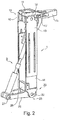
- an orthopedic device 1 in the form of a lower leg prosthesis according to FIG. 2 proposed, which has a knee joint 10 with a proximal upper part 11 and an articulated about a knee axis 12 attached thereto lower part 13.
- a lower leg part 14 is attached, which establishes a connection to the ankle joint 20 and about an ankle joint axis 22 is pivotally mounted on a foot part 23.
- the foot part 23 is formed in the illustrated embodiment as a receptacle for a Justierkern for a prosthetic foot and has a boom 25 which is directed in the illustrated embodiment in the direction of walking forward, so anterior oriented.
- the lower part 13 and the lower leg part 14 have slot guides, so that the two components are slidably mounted to each other in order to make a length adjustment, if desired or necessary.
- the lower part 13 consists of two side plates, which are attached to also designed as side plates lower leg portions 14, the side panels are opaque to each other.
- a stop 16 is provided for limiting the maximum extension angle, as well as an ankle stop 26 is provided on the lower leg portion 14, which limits the maximum Dorsalflexion of the foot part 23.
- the lower end of the coupling element is hinged at a distal pivot point 27 on the distal arm 25, but immovably. Due to the arrangement of the articulation points 17, 27 posteriorly and anteriorly of a connecting line between the knee axis 12 and the ankle joint axis 22, a bending of the knee joint 10 due to the rotation of the eccentric to the knee axis 12 mounted proximal articulation point 17 in the clockwise direction leads to a displacement of the coupling element and a rotation of the distal arm 25 about the ankle joint axis 22 in the counterclockwise direction, so that the foot part 23 is flexed with the thereto attached, not shown prosthetic foot in a knee flexion in Plantarraum.
- FIG. 3 is in a sectional side view of the prosthesis 1 according to FIG. 2 shown in a starting position, which corresponds to the standing.
- the knee joint 10 is in the maximum extension and the extension 25 of the ankle joint 20 is substantially perpendicular to the longitudinal extent of both the lower leg part 14 and the lower part 13 and the connecting line between the knee axis 12 and the ankle joint axis 22.
- the slot guide for the proximal pivot point 17 can be seen, as well as the proximal lever length X, which can be variably adjusted.
- the ankle lever length Y which represents the distance between the distal pivot point 27 and the ankle joint axis 22, is located.
- the mechanical power transmission device 3 with a distal sleeve 30 which articulates on the ankle bracket 25 is mounted, a double screw 31 with opposing threads and a proximal sleeve 32 which is pivotally mounted about a hinge axis 33 on a clip 35.
- a stop 34 is formed, which prevents the proximal sleeve 32 in the clockwise direction about the axis 33 deflects beyond a predetermined angle.
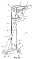
- FIG. 3a is in a perspective view according to FIG. 3 the prosthesis 1 shown.
- the ankle bracket 25 is formed as a fork open on one side, which has two legs, between which the distal sleeve 30 is pivotally mounted at the distal pivot point 27.
- the distal sleeve 30 and the proximal sleeve 32 have an internal thread into which the double screw 31 is screwed.
- the proximal sleeve 32 is mounted about the hinge axis 33 on the clip 35, which in turn is attached to the proximal arm 15.
- the upper part 10 is articulated about pins about the pivot axis 12 to the lower part 13, the stop 34 prevents pivoting of the proximal sleeve 32 in the clockwise direction about the hinge axis 33 beyond the predetermined amount, which is determined by the stop 34.
- the Dorsalflexionsanschlag 26 is adjustable, so that the maximum Dorsalflexion is variably adjustable.
- the prosthesis 1 is shown in an inflexible state. While in the FIG. 3 the knee angle ⁇ was 0 °, is in the FIG. 4 a knee angle of about 50 ° provided.
- the plantar flexion angle ⁇ which in the position according to FIG. 3 0 ° was, is in the FIG. 4 about 25 °, which can be varied over the different lever lengths X, Y in the respective arms 15, 25.
- the lever length Y on the ankle bracket 25 is adjustable, the gear ratio can be performed in conjunction with a length adjustment on the double screw 31 easy and varied.
- the initial position ie the plantar flexion angle ⁇ as a function of the knee angle ⁇ in the position according to FIG FIG.
- the power transmission device 3 can be adjusted via the double screw 31 and the position of the proximal pivot point 17 within the slot guide. If the double screw 31 from the threads rotated in the sleeves 30, 32, the power transmission device 3, so that at a constant position of the articulation points 17, 27, the foot part 23 is flexed in the plantar direction, conversely, a dorsiflexion is initiated in the opposite direction.
- FIG. 4 is the maximum knee angle ⁇ shown for the embodiment up to which the force transmission device from the two sleeves 30, 32, the double screw 31 and the clip 35, a compressive force on the distal arm 25 can be transmitted without the distal sleeve 32 to the Axis 33 pivots.
- the clasp 35 may be formed a stop, also a further rotation of the clasp 35 relative to the boom 15 can be prevented by other means, so that in a further bending in the knee joint 10, the distal end of the clasp 35 is displaced in the clockwise direction, so that a buckling takes place in the power transmission device 3, which leads to a shortening of the effective length between the two articulation points 17, 27.
- the force transmission device 3 essentially transmits tractive force when the knee joint 10 is bent in.
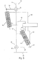
- FIG. 5 a basic structure of a hydraulic power transmission device 3 is shown.
- boom 15, 25 are provided on the knee joint 10 and the ankle joint 20, in a very simple embodiment of the knee joint 10, the lower part 13 at the same time form the connection between the knee joint 10 and the ankle joint 20.
- the knee joint 10 is formed as a separate component and has an upper part 11 and a lower part 13, to which a lower leg tube or lower leg part 14 can be fastened via fastening means, which in turn is fixed to attachment means of the ankle joint 20 of a prosthetic foot.
- a first hydraulic cylinder-piston unit 40 is mounted on the proximal articulation point 17 and on the lower part 13.
- a distal cylinder-piston unit 41 Via hydraulic lines 42, which open into a valve block 43, is a distal cylinder-piston unit 41 with the proximal cylinder-piston unit 40 in fluid communication.
- the distal piston-cylinder unit 41 is optionally mounted on the lower part 13 or a lower leg part and on the boom 25 at the distal pivot point 27.
- the two hydraulic units 40, 41 are formed as two synchronous cylinders, which are configured the same volume and diameter.
- An individual translation can be realized by different levers on the knee joint 10 and the ankle joint 20.
- valve block 43 several and different valves may be provided to interconnect all cylinder volumes with each other arbitrarily, in order to set different plantar flexion angle ⁇ at desired knee angle positions can.
- valve block 43 there may be proportional valves through which it is possible to make restrictions, so that different hydraulic resistances can be provided.
- FIG. 6 a schematic side view of a prosthetic device with hydraulic power transmission. Similar to the embodiment according to FIG. 2 is in the proximal arm 15, a slot guide provided in which the upper pivot point 17 of the proximal piston-cylinder unit 40 is mounted. About a fixing device, the lever length X and thus the mechanical translation can be adjusted.
- a pyramid adapter mounted, on the lower part 13 of the knee joint 10 with the side plates height-adjustable lower leg parts 14 are mounted, between which the distal piston-cylinder unit 41 is arranged.
- the lower pivot point 27 is rotatably but immovably mounted on the distal arm 25, may be arranged on the sensors, for example in the form of strain gauges to detect the load.
- the valve block 43 is provided with a control device 44, in which a switching electronics is housed, so that the arranged within the valve block 43 valves for different coupling of the cylinder in the cylinder-piston units 40, 41 can be controlled individually and after evaluation of sensor data.
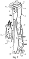
- FIG. 7 is a perspective view of the embodiment according to FIG. 6 2, it can be seen that the hydraulic cylinder units 40, 41 are arranged between the lower leg parts 14 and lower parts 13 which are designed as side plates. Also, the valve block 43 may be disposed between the side plates.
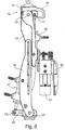
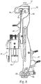
- FIG. 8 a variant of the invention is shown, in which both in the knee joint 10 and in the ankle joint 20 angle sensors 50 are coupled to the control unit 44, so that depending on the knee angle ⁇ and the plantar flexion angle ⁇ an interconnection of the valves within the valve block 43 are performed angle-dependent can. It is also possible to provide other sensors, such as position sensors or force or torque sensors, to determine the position in space, forces or moments and to use for controlling the valves.
- FIG. 8a is a sectional view of FIG. 8 shown.
- a piston rod 420 of the proximal cylinder-piston unit 40 is attached.
- a piston 410 is fixed, which is guided in a housing 400 of the piston-cylinder unit 40.
- the piston 410 of the proximal cylinder-piston unit 40 is located at the proximal stop.
- hydraulic fluid is passed in a flexion movement of the distal cylinder chamber to the distal cylinder-piston unit 41.
- hydraulic fluid is directed into the proximal cylinder chamber of the distal cylinder-piston unit 41 when the knee joint is bent, so that the distal piston rod 420 is displaced in the direction of the distal bearing 27, so that a plantarflexion about the ankle joint axis 22 established.
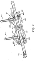
- FIG. 9 shows a detailed view of a piston-cylinder unit with a housing 400 in which a piston 410 is attached to a piston rod 420.
- Two end stops 430 limit the volume bounded by the housing 400.
- the cylinders formed by the housing 400 are closed by cover 440.
- plain bearings 450 and scrapers 460 are integrated.
- hose connections 470 are provided, which are connected to hydraulic lines 42, which are not shown.
- a bearing pin 480 is arranged, which can be arranged in one of the articulation points 17, 27 of the boom 15, 25.
- the bearing pin 480 can be provided as a joint head with two axle bolts for mounting on the arms 15, 25, a second bearing point is in the perspective view according to FIG. 10 shown.
- the axle bolts 490 in the housing 400 serve for mounting in the side plates of either the lower part 13 or the lower leg part 14.
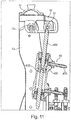
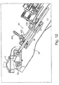
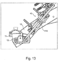
- FIGS. 11 to 13 is shown in a sectional view, the proximal piston-cylinder unit 40 in different knee angle positions.
- the knee angle is 0 °
- the piston 410 within the housing 400 is then in the maximum position at the proximal end stop. All hydraulic fluid has been forced out of the proximal cylinder and the volume of the distal cylinder is maximum.
- FIG. 12 is a knee angle position shown with a knee angle ⁇ of 60 °.
- the piston 410 is located beyond the center of the housing 400 such that the proximal cylinder has a larger volume than the distal cylinder.
- the piston 410 inside the cylinder went down moved and hydraulic fluid from the lower cylinder through the valves to the unillustrated distal piston-cylinder unit 41 passed.
- FIG. 13 shows a position of the knee joint with a knee angle ⁇ of 120 °, as it is taken for example when kneeling or squatting.
- the position of the piston 410 corresponds to that of FIG. 12 However, the piston 410 has already reached the distal end stop at a position of a knee angle ⁇ of 90 °.
- the reversal of movement of the piston 410 when passing through the knee angle of 90 ° can either lead to reversal of motion in the control of the ankle joint 20 or be compensated by switching the valves.
- FIG. 14 shows the arrangement of a piston-cylinder unit 41 on the ankle joint 20 with a dorsiflexion, in which the piston 410 is positioned near the proximal end stop 430.
- FIG. 15 shows a maximum flexed ankle joint 20, for example at a knee angle ⁇ of 90 °.
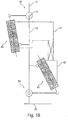
- FIG. 16 shows a schematic representation of different Verschaltungsten.
- the tube connections 470 can be connected in parallel, it is also possible that the tube connections 470 of the distal piston-cylinder unit 41 are cross-connected to the tube connections 470 of the proximal piston-cylinder unit 40. It is also possible that the piston-cylinder units 40, 41 are switched independently, so that there is no functional connection between the units.
- the knee joint 10 and the ankle joint 20 are thus freely movable independently of one another, optionally the damping in the knee joint 10 and / or the ankle joint 20 can be set via a throttle valve. If the proximal piston-cylinder unit 40 is unlocked while the distal piston-cylinder unit is locked, the knee joint 10 is free to move and the ankle joint 20 is rigid, with a blockage of both piston-cylinder units 40, 41 both joints are rigid.
- the controlled flexion and extension in the ankle joint 20 as a function of the knee angle ⁇ and a coupling of the plantar flexion as a function of the knee flexion it is possible to use the kinetic energy of the knee for the ankle movement. This will lengthen the effective leg length during knee flexion reached at the end of the stance phase and thereby extends the duration of the ground contact, whereby the vertical movement of the body center of gravity during the transition is minimized. This leads to an approximation of the natural gait pattern.
- the dorsiflexion in the swing phase makes it possible to shorten the effective leg length again in order to minimize the risk of stumbling. Due to the direct implementation of the mechanical energy with minimal power loss, it is possible to achieve a high energy efficiency with a relatively low weight in comparison to known orthotic devices, in particular prostheses with motorized adjustment.
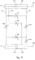
- FIG. 17 are the two cylinder-piston units 40, 41, which are associated with the knee joint and the ankle joint, shown schematically in the respective neutral position.
- the hydraulic lines 42 connect the cylinder chambers with each other in parallel, the hydraulic lines 42 are interconnected by two transverse lines, a diagonal line connects a cylinder chamber facing away from the piston rods 420 with a cylinder chamber of the distal cylinder-piston unit 41 facing the piston rod 420.
- each of the hydraulic lines 42 at least one valve 431, 432, 433, 434, 435, 436 is arranged in order to realize different interconnections.
- a parallel circuit results which causes a displacement of the upper piston 410 to the left to a displacement of the lower piston 410 to the right.
- the cylinder-piston units 40, 42 must be cross-connected, to which the valves 431, 434 and 435 are closed, while the valves 432, 433 and 436 are open.
- valves 433, 434 and 436 are closed, this leads to a decoupling of the proximal piston-cylinder unit 40 from the distal cylinder-piston unit 41.
- By partially closing the opened valves 431, 432 and 435 it is possible to adjust the resistance to displacement.
- the ankle joint remains rigid, whereas the knee joint can be bent, the resistance to the deflection results from the hydraulic resistance of the open valve 431.
- a rigid knee joint and a movable ankle joint is possible when the valves 432 , 435 opened and the remaining valves remain closed.
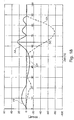
- FIG. 18 shows the course of the knee angle KA and the ankle angle AA in a prosthetic knee joint with a coupling device according to the invention over a gait cycle.
- the so-called heel strike there is a plantarflexion PF of the ankle joint, for example against a spring force that holds the ankle joint in the starting position.
- the plantar flexion after the heel strike is effected by the transmission of forces from the knee flexion by the power transmission and superimposed on the dorsiflexion force of the return spring, which subsequently progressively releases the oppositely directed forces after approximately one quarter of the step duration leads.
- the ankle joint angle is then 0 ° again.
- the force introduction point moves in front of the ankle joint after approximately one third of the step time, resulting in dorsiflexion DF.
- the knee angle KA increases, at the same time a plantar flexion is initiated, which transfers forces occurring during knee flexion to the ankle joint.
- decoupling DC of the ankle joint from the knee joint occurs so that the knee joint can swing freely back while the ankle joint is returned to the home position upon reaching maximum plantar flexion. Due to a non-existing damper this return movement takes place in the form of a decaying vibration.
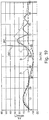
- FIG. 19 shows various ankle joint angle curves over a step duration, wherein the curves A and B show angular courses, which are achieved with a device according to the invention, curve C shows the course of a conventional ankle joint.
- the curves A and B reach a plantarflexion angle between 8 ° and 10 °, while a conventional ankle joint has a dorsiflexion of about 8 °.
- the curve A provides damping, in the curve C, the initial state is reached very quickly after the end of the ground contact again.
- the power transmission device (3, 30, 31, 32, 35, 40, 41, 42) is preferably designed as a hydraulic system or as a mechanical coupling device transmitting tensile and / or compressive force.
- the mechanical coupling device (30, 31, 32, 35) is preferably mounted on a first bearing point (15) protruding dorsally or ventrally to the knee axis (12) and mounted on a second bearing point (25) at an anterior or posterior to the ankle joint axis, wherein the Storage points (15, 25) lie on different sides of a connecting line between a knee axis (12) and ankle joint axis (22).
- the mechanical coupling device (30, 31, 32, 35) is designed as a joint rod or traction means.
- the first storage location (15) is adjustable.
- the hydraulic power transmission device (40, 41, 42) preferably has a control device (44) in order to enable or interrupt power transmission.
- the control device (44) is preferably coupled to at least one sensor (50) in order to control a power transmission as a function of sensor values.
- a cylinder-piston unit (40, 41) is arranged on the upper part (11) or the thigh part and the lower leg part (14) or the foot part (23), which are interconnected by at least one hydraulic line (42).
- the cylinder-piston units (40, 41) via valves (43) are connected to each other in parallel or crosswise or individually adjustable.
- a sensor device (50) for detecting the knee angle (a) and / or a Plantarflexionswinkels ( ⁇ ) is provided which is connected to a control device (44) for adjusting the valve (43) or the valves (43).
- the power transmission device (3, 30, 31, 32, 35, 40, 41, 42) preferably blocks power transmission in the dorsiflexion direction.
- the maximum Dorsalflexions ein the foot part (23) is designed to be variable adjustable.
- a return device is assigned to the foot part (23) in order to effect a dorsiflexion of the foot part (23).
- the ankle joint (20) is designed as an elastic joint and exerts a restoring force at a deflection from a starting position.
- At least one damper which counteracts dorsiflexion is present in the ankle joint (20).
Landscapes
- Health & Medical Sciences (AREA)
- Transplantation (AREA)
- Public Health (AREA)
- Life Sciences & Earth Sciences (AREA)
- Veterinary Medicine (AREA)
- Engineering & Computer Science (AREA)
- Biomedical Technology (AREA)
- Heart & Thoracic Surgery (AREA)
- Vascular Medicine (AREA)
- General Health & Medical Sciences (AREA)
- Animal Behavior & Ethology (AREA)
- Orthopedic Medicine & Surgery (AREA)
- Cardiology (AREA)
- Oral & Maxillofacial Surgery (AREA)
- Nursing (AREA)
- Prostheses (AREA)
Applications Claiming Priority (4)
| Application Number | Priority Date | Filing Date | Title |
|---|---|---|---|
| DE102012023023.0A DE102012023023B4 (de) | 2012-11-26 | 2012-11-26 | Orthopädietechnische Vorrichtung |
| EP13817649.0A EP2922505B1 (fr) | 2012-11-26 | 2013-11-26 | Dispositif orthopédique |
| PCT/EP2013/003567 WO2014079588A1 (fr) | 2012-11-26 | 2013-11-26 | Dispositif orthopédique |
| EP17178057.0A EP3257478B1 (fr) | 2012-11-26 | 2013-11-26 | Dispositif orthopédique |
Related Parent Applications (2)
| Application Number | Title | Priority Date | Filing Date |
|---|---|---|---|
| EP13817649.0A Division EP2922505B1 (fr) | 2012-11-26 | 2013-11-26 | Dispositif orthopédique |
| EP17178057.0A Division EP3257478B1 (fr) | 2012-11-26 | 2013-11-26 | Dispositif orthopédique |
Publications (2)
| Publication Number | Publication Date |
|---|---|
| EP3498232A2 true EP3498232A2 (fr) | 2019-06-19 |
| EP3498232A3 EP3498232A3 (fr) | 2019-07-10 |
Family
ID=49917631
Family Applications (3)
| Application Number | Title | Priority Date | Filing Date |
|---|---|---|---|
| EP19150758.1A Withdrawn EP3498232A3 (fr) | 2012-11-26 | 2013-11-26 | Dispositiv orthopédique |
| EP13817649.0A Active EP2922505B1 (fr) | 2012-11-26 | 2013-11-26 | Dispositif orthopédique |
| EP17178057.0A Active EP3257478B1 (fr) | 2012-11-26 | 2013-11-26 | Dispositif orthopédique |
Family Applications After (2)
| Application Number | Title | Priority Date | Filing Date |
|---|---|---|---|
| EP13817649.0A Active EP2922505B1 (fr) | 2012-11-26 | 2013-11-26 | Dispositif orthopédique |
| EP17178057.0A Active EP3257478B1 (fr) | 2012-11-26 | 2013-11-26 | Dispositif orthopédique |
Country Status (7)
| Country | Link |
|---|---|
| US (3) | US9993356B2 (fr) |
| EP (3) | EP3498232A3 (fr) |
| CN (2) | CN104797216B (fr) |
| BR (1) | BR112015011316A8 (fr) |
| DE (1) | DE102012023023B4 (fr) |
| RU (1) | RU2652893C2 (fr) |
| WO (1) | WO2014079588A1 (fr) |
Families Citing this family (32)
| Publication number | Priority date | Publication date | Assignee | Title |
|---|---|---|---|---|
| WO2015130855A1 (fr) * | 2014-02-25 | 2015-09-03 | Jumpsport, Inc. | Dispositif d'exercice de rééducation d'articulation et du genou |
| US11013622B2 (en) * | 2014-12-18 | 2021-05-25 | Ottobock Se & Co. Kgaa | Prosthetic joint with a mechanical response system to position and rate of change |
| GB201502504D0 (en) * | 2015-02-13 | 2015-04-01 | Boender Jonah A B And Boender Jacob Q L | A hydraulic prosthetic joint |
| DE102015106389B4 (de) * | 2015-04-24 | 2016-11-10 | Otto Bock Healthcare Products Gmbh | Verfahren zur Steuerung eines künstlichen Kniegelenkes |
| US12059383B2 (en) | 2016-05-03 | 2024-08-13 | Icarus Medical, LLC | Assistive orthotic device with motors and sensors |
| US11612506B2 (en) | 2016-05-03 | 2023-03-28 | Icarus Medical, LLC | Unloading knee-ankle-foot orthotic apparatus with conforming and distracting hinge |
| US11278434B2 (en) | 2017-06-06 | 2022-03-22 | Ottobock Se & Co. Kgaa | Orthopedic joint device |
| DE102017112911B4 (de) | 2017-06-12 | 2024-09-05 | Otto Bock Healthcare Products Gmbh | Gelenkeinrichtung |
| DE102017128618A1 (de) * | 2017-12-01 | 2019-06-06 | Ottobock Se & Co. Kgaa | Orthese, System und Verfahren zum Anpassen einer Orthese |
| DE102017131319B4 (de) * | 2017-12-27 | 2019-07-04 | Otto Bock Healthcare Products Gmbh | Orthopädietechnische Einrichtung und Verfahren zu deren Steuerung |
| CN108210132B (zh) * | 2017-12-29 | 2019-07-19 | 国家康复辅具研究中心 | 一种单源仿生动力膝关节及其实现方法 |
| DE102018103884A1 (de) | 2018-02-21 | 2019-08-22 | Otto Bock Healthcare Products Gmbh | Hydraulikaktuator |
| CN108542565B (zh) * | 2018-04-08 | 2024-01-12 | 徐立彪 | 数字三维人体关节功能矫正康复治疗仪 |
| CN108433941B (zh) * | 2018-04-08 | 2024-03-01 | 徐立彪 | 数字三维人体下肢关节功能矫正康复治疗仪 |
| WO2019221037A1 (fr) * | 2018-05-14 | 2019-11-21 | 株式会社今仙技術研究所 | Composant d'articulation de genou, articulation de genou et jambe artificielle |
| DE102018112724B3 (de) * | 2018-05-28 | 2019-08-29 | Johannes Klopf | Oberschenkelprothesenpassteil |
| DE102018117377B3 (de) | 2018-07-18 | 2019-09-05 | Ottobock Se & Co. Kgaa | Orthopädietechnische Vorrichtung |
| EP3821220B1 (fr) | 2018-08-22 | 2024-11-13 | University of Utah Research Foundation | Capteur de force et de couple pour dispositifs prothétiques et orthopédiques |
| US12070398B2 (en) | 2018-08-28 | 2024-08-27 | University Of Utah Research Foundation | Variable transmission for assistive prosthesis device |
| CN109223264B (zh) * | 2018-11-13 | 2023-11-21 | 深圳先进技术研究院 | 一种膝关节假肢及控制方法 |
| DE102018131698A1 (de) * | 2018-12-11 | 2020-06-18 | Ottobock Se & Co. Kgaa | Dämpfersystem |
| CN110478100B (zh) * | 2019-07-26 | 2022-06-24 | 四川护理职业学院附属医院 | 脑瘫儿童智能踝足矫正训练器 |
| DE102019121234B3 (de) * | 2019-08-06 | 2021-01-07 | Ottobock Se & Co. Kgaa | Orthopädietechnische Vorrichtung |
| DE202019104682U1 (de) * | 2019-08-27 | 2019-09-05 | Johannes Klopf | Fußgelenk sowie Oberschenkelprothesenpassteil |
| JP7390639B2 (ja) * | 2019-09-04 | 2023-12-04 | カヤバ株式会社 | 歩行補助装置 |
| US12064360B2 (en) * | 2019-11-09 | 2024-08-20 | Tarbiat Modares University | Prosthetic foot |
| US12048668B2 (en) | 2020-03-20 | 2024-07-30 | The University Of Utah Research Foundation | Self-aligning mechanisms in passive and powered exoskeletons |
| DE102020125256A1 (de) | 2020-09-28 | 2022-03-31 | Otto Bock Healthcare Products Gmbh | Verfahren zur Steuerung eines Prothesenfußes |
| CN113332096A (zh) * | 2021-06-03 | 2021-09-03 | 江苏大学 | 一种纯机械驱动的便携式膝关节康复锻炼装置 |
| DE102021132201A1 (de) * | 2021-12-07 | 2023-06-07 | Ottobock Se & Co. Kgaa | Gelenk und Verfahren zum Einstellen einer Ausgangsposition |
| CN115192276B (zh) * | 2022-06-30 | 2024-05-17 | 吉林大学 | 一种膝踝一体化仿生下肢假肢 |
| IT202300026352A1 (it) * | 2023-12-11 | 2025-06-11 | Fondazione St Italiano Tecnologia | Protesi sotto-attuata e reversibile per ginocchio e caviglia |
Family Cites Families (27)
| Publication number | Priority date | Publication date | Assignee | Title |
|---|---|---|---|---|
| US111741A (en) * | 1871-02-14 | Improvement in artificial legs | ||
| GB245577A (en) * | 1924-12-16 | 1926-01-14 | Charles Dixon | Artificial limbs |
| DE475303C (de) | 1927-10-21 | 1929-04-23 | Wilhelm Lang | Kuenstliches Bein |
| US2478721A (en) * | 1946-08-10 | 1949-08-09 | John H F Stewart | Artificial limb |
| US2605474A (en) * | 1947-11-22 | 1952-08-05 | Adel Prec Products Corp | Hydraulically controlled artificial leg |
| DE3167157D1 (en) | 1980-05-28 | 1984-12-20 | Roberto Serri | Articulated prosthesis for the lower extremity |
| FR2549719B1 (fr) | 1983-07-29 | 1986-09-26 | Altermatt H Et Fils | Prothese de jambe mecanisee pour personnes amputees |
| SU1505538A1 (ru) * | 1987-10-15 | 1989-09-07 | Алма-Атинский институт инженеров железнодорожного транспорта | Протез бедра |
| JP3599548B2 (ja) | 1997-12-18 | 2004-12-08 | 株式会社日立製作所 | 半導体集積回路装置の製造方法 |
| CN2350013Y (zh) * | 1998-12-04 | 1999-11-24 | 山东省假肢矫形康复中心 | 储能假脚 |
| US20040064195A1 (en) | 2002-07-15 | 2004-04-01 | Hugh Herr | Variable-mechanical-impedance artificial legs |
| RU2254832C1 (ru) * | 2003-11-26 | 2005-06-27 | Общество с ограниченной ответственностью "МЕТИЗ" | Искусственный коленный сустав с регулированием сил подтормаживания раздельно при сгибании и разгибании |
| DE102004037877B4 (de) * | 2004-08-04 | 2010-04-29 | Bauerfeind Ag | Fußprothese |
| US7942935B2 (en) | 2005-03-29 | 2011-05-17 | Motion Control | Device and system for prosthetic knees and ankles |
| US20060249315A1 (en) | 2005-03-31 | 2006-11-09 | Massachusetts Institute Of Technology | Artificial human limbs and joints employing actuators, springs, and variable-damper elements |
| SE528516C2 (sv) | 2005-04-19 | 2006-12-05 | Lisa Gramnaes | Kombinerat aktivt och passivt benprotessystem samt en metod för att utföra en rörelsecykel med ett sådant system |
| US8974542B2 (en) | 2006-06-27 | 2015-03-10 | University of Pittsburgh—of the Commonwealth System of Higher Education | Biodegradable elastomeric patch for treating cardiac or cardiovascular conditions |
| US20080269913A1 (en) | 2007-04-26 | 2008-10-30 | Rego Florida Corporation | Artificial leg |
| DE102008008282B4 (de) | 2008-02-07 | 2014-04-03 | Otto Bock Healthcare Gmbh | Orthopädisches Fußteil und Verfahren zur Steuerung eines künstlichen Fußes |
| US8652218B2 (en) | 2008-04-21 | 2014-02-18 | Vanderbilt University | Powered leg prosthesis and control methodologies for obtaining near normal gait |
| US8974543B2 (en) | 2008-04-30 | 2015-03-10 | Rizzoli Ortopedia S.P.A. | Automatic prosthesis for above-knee amputees |
| DE102009052890A1 (de) | 2009-11-13 | 2011-05-19 | Otto Bock Healthcare Products Gmbh | Vorrichtung und Verfahren zur Steuerung eines künstlichen orthetischen oder prothetischen Gelenkes |
| IT1396692B1 (it) | 2009-11-18 | 2012-12-14 | Rizzoli Ortopedia S P A | Struttura di protesi per amputati agli arti inferiori. |
| BR112013007120A2 (pt) * | 2010-10-25 | 2016-06-14 | Bock Healthcare Gmbh | pé protético |
| WO2012177125A1 (fr) | 2011-06-21 | 2012-12-27 | Universiteit Twente | Dispositif prothétique ou orthétique |
| RU135255U1 (ru) | 2013-03-29 | 2013-12-10 | Федеральное государственное бюджетное образовательное учреждение высшего профессионального образования "Московский государственный университет имени М.В. Ломоносова" (МГУ) | Коленное сочленение экзоскелетона |
| US9913738B1 (en) * | 2013-05-15 | 2018-03-13 | Raymond Fikes | Conditional braking knee |
-
2012
- 2012-11-26 DE DE102012023023.0A patent/DE102012023023B4/de active Active
-
2013
- 2013-11-26 RU RU2015125274A patent/RU2652893C2/ru active
- 2013-11-26 EP EP19150758.1A patent/EP3498232A3/fr not_active Withdrawn
- 2013-11-26 EP EP13817649.0A patent/EP2922505B1/fr active Active
- 2013-11-26 WO PCT/EP2013/003567 patent/WO2014079588A1/fr not_active Ceased
- 2013-11-26 CN CN201380061045.3A patent/CN104797216B/zh active Active
- 2013-11-26 CN CN201710623978.7A patent/CN107361887B/zh active Active
- 2013-11-26 EP EP17178057.0A patent/EP3257478B1/fr active Active
- 2013-11-26 US US14/646,705 patent/US9993356B2/en active Active
- 2013-11-26 BR BR112015011316A patent/BR112015011316A8/pt not_active Application Discontinuation
-
2018
- 2018-05-10 US US15/976,636 patent/US10893959B2/en active Active
-
2020
- 2020-09-09 US US17/016,320 patent/US11730611B2/en active Active
Also Published As
| Publication number | Publication date |
|---|---|
| DE102012023023A1 (de) | 2014-05-28 |
| RU2015125274A (ru) | 2017-01-10 |
| US20150305895A1 (en) | 2015-10-29 |
| BR112015011316A8 (pt) | 2019-10-01 |
| CN104797216A (zh) | 2015-07-22 |
| EP3257478B1 (fr) | 2019-01-09 |
| WO2014079588A1 (fr) | 2014-05-30 |
| CN104797216B (zh) | 2017-07-21 |
| US10893959B2 (en) | 2021-01-19 |
| CN107361887B (zh) | 2019-06-18 |
| EP2922505A1 (fr) | 2015-09-30 |
| BR112015011316A2 (pt) | 2017-07-11 |
| US11730611B2 (en) | 2023-08-22 |
| RU2652893C2 (ru) | 2018-05-03 |
| CN107361887A (zh) | 2017-11-21 |
| EP3257478A1 (fr) | 2017-12-20 |
| EP2922505B1 (fr) | 2017-06-28 |
| DE102012023023B4 (de) | 2023-02-16 |
| US20200405507A1 (en) | 2020-12-31 |
| US9993356B2 (en) | 2018-06-12 |
| US20180256372A1 (en) | 2018-09-13 |
| EP3498232A3 (fr) | 2019-07-10 |
Similar Documents
| Publication | Publication Date | Title |
|---|---|---|
| EP3257478B1 (fr) | Dispositif orthopédique | |
| EP3823564B1 (fr) | Dispositif orthopédique comportant une partie pied, une partie jambe et une partie cuisse | |
| EP3137020B1 (fr) | Prothèse | |
| EP2276433B1 (fr) | Orthèse de genou | |
| EP3731786B1 (fr) | Dispositif orthopédique et procédé pour en assurer la commande | |
| EP2816979A1 (fr) | Procédé de commande d'une articulation de genou artificielle d'une orthèse ou prothèse | |
| DE102008008284A1 (de) | Orthopädisches Kniegelenk sowie Verfahren zur Steuerung eines orthopädischen Kniegelenkes | |
| WO2016174096A1 (fr) | Prothèse de pied | |
| WO2017050552A1 (fr) | Dispositif articulaire orthopédique | |
| WO2020148373A1 (fr) | Procédé pour la commande d'un dispositif orthétique ou prothétique et dispositif orthétique ou prothétique | |
| EP2316390B1 (fr) | Genouillère pour une prothèse | |
| WO2019106144A1 (fr) | Orthèse, système et procédé d'adaptation d'une orthèse | |
| WO2018224552A1 (fr) | Dispositif d'articulation orthopédique | |
| WO2016066157A1 (fr) | Prothèse | |
| DE102019121234B3 (de) | Orthopädietechnische Vorrichtung | |
| DE102015113977A1 (de) | Künstliches Gelenk | |
| WO2020126695A1 (fr) | Dispositif prothétique | |
| WO2021037558A1 (fr) | Articulation de cheville et composant de prothèse fémorale |
Legal Events
| Date | Code | Title | Description |
|---|---|---|---|
| PUAI | Public reference made under article 153(3) epc to a published international application that has entered the european phase |
Free format text: ORIGINAL CODE: 0009012 |
|
| STAA | Information on the status of an ep patent application or granted ep patent |
Free format text: STATUS: THE APPLICATION HAS BEEN PUBLISHED |
|
| PUAL | Search report despatched |
Free format text: ORIGINAL CODE: 0009013 |
|
| AC | Divisional application: reference to earlier application |
Ref document number: 2922505 Country of ref document: EP Kind code of ref document: P Ref document number: 3257478 Country of ref document: EP Kind code of ref document: P |
|
| AK | Designated contracting states |
Kind code of ref document: A2 Designated state(s): AL AT BE BG CH CY CZ DE DK EE ES FI FR GB GR HR HU IE IS IT LI LT LU LV MC MK MT NL NO PL PT RO RS SE SI SK SM TR |
|
| AK | Designated contracting states |
Kind code of ref document: A3 Designated state(s): AL AT BE BG CH CY CZ DE DK EE ES FI FR GB GR HR HU IE IS IT LI LT LU LV MC MK MT NL NO PL PT RO RS SE SI SK SM TR |
|
| RIC1 | Information provided on ipc code assigned before grant |
Ipc: A61F 2/76 20060101ALN20190531BHEP Ipc: A61F 2/66 20060101ALN20190531BHEP Ipc: A61F 2/60 20060101AFI20190531BHEP Ipc: A61F 2/68 20060101ALI20190531BHEP Ipc: A61F 5/01 20060101ALI20190531BHEP Ipc: A61F 2/74 20060101ALN20190531BHEP Ipc: A61F 2/64 20060101ALN20190531BHEP Ipc: A61F 2/50 20060101ALN20190531BHEP Ipc: A61F 2/70 20060101ALI20190531BHEP |
|
| STAA | Information on the status of an ep patent application or granted ep patent |
Free format text: STATUS: REQUEST FOR EXAMINATION WAS MADE |
|
| 17P | Request for examination filed |
Effective date: 20200102 |
|
| RBV | Designated contracting states (corrected) |
Designated state(s): AL AT BE BG CH CY CZ DE DK EE ES FI FR GB GR HR HU IE IS IT LI LT LU LV MC MK MT NL NO PL PT RO RS SE SI SK SM TR |
|
| STAA | Information on the status of an ep patent application or granted ep patent |
Free format text: STATUS: EXAMINATION IS IN PROGRESS |
|
| 17Q | First examination report despatched |
Effective date: 20230414 |
|
| STAA | Information on the status of an ep patent application or granted ep patent |
Free format text: STATUS: THE APPLICATION IS DEEMED TO BE WITHDRAWN |
|
| 18D | Application deemed to be withdrawn |
Effective date: 20231025 |