EP3496936B1 - Gurt aus vorgefertigten elementen mit gelege und ein verfahren zu seiner fertigung - Google Patents
Gurt aus vorgefertigten elementen mit gelege und ein verfahren zu seiner fertigung Download PDFInfo
- Publication number
- EP3496936B1 EP3496936B1 EP17751381.9A EP17751381A EP3496936B1 EP 3496936 B1 EP3496936 B1 EP 3496936B1 EP 17751381 A EP17751381 A EP 17751381A EP 3496936 B1 EP3496936 B1 EP 3496936B1
- Authority
- EP
- European Patent Office
- Prior art keywords
- layers
- rodpack
- pultrudate
- longitudinal direction
- woven
- Prior art date
- Legal status (The legal status is an assumption and is not a legal conclusion. Google has not performed a legal analysis and makes no representation as to the accuracy of the status listed.)
- Active
Links
- 239000004744 fabric Substances 0.000 title description 57
- 238000004519 manufacturing process Methods 0.000 title description 13
- 239000000835 fiber Substances 0.000 claims description 51
- 238000000034 method Methods 0.000 claims description 30
- 239000011347 resin Substances 0.000 claims description 22
- 229920005989 resin Polymers 0.000 claims description 22
- 150000001875 compounds Chemical class 0.000 claims 1
- 239000011265 semifinished product Substances 0.000 description 14
- 238000001802 infusion Methods 0.000 description 11
- 239000000463 material Substances 0.000 description 8
- 229920000049 Carbon (fiber) Polymers 0.000 description 3
- 238000005452 bending Methods 0.000 description 3
- 239000004917 carbon fiber Substances 0.000 description 3
- 239000003365 glass fiber Substances 0.000 description 3
- 238000003475 lamination Methods 0.000 description 3
- 238000010438 heat treatment Methods 0.000 description 2
- 238000009434 installation Methods 0.000 description 2
- 239000000203 mixture Substances 0.000 description 2
- 238000006243 chemical reaction Methods 0.000 description 1
- 238000010276 construction Methods 0.000 description 1
- 230000001419 dependent effect Effects 0.000 description 1
- 238000009826 distribution Methods 0.000 description 1
- 230000009969 flowable effect Effects 0.000 description 1
- 238000001746 injection moulding Methods 0.000 description 1
- 238000010030 laminating Methods 0.000 description 1
- 239000007788 liquid Substances 0.000 description 1
- 239000011159 matrix material Substances 0.000 description 1
- 230000035515 penetration Effects 0.000 description 1
- 229920006395 saturated elastomer Polymers 0.000 description 1
- 238000001721 transfer moulding Methods 0.000 description 1
- 230000007704 transition Effects 0.000 description 1
- 238000009966 trimming Methods 0.000 description 1
Images

Classifications
-
- B—PERFORMING OPERATIONS; TRANSPORTING
- B29—WORKING OF PLASTICS; WORKING OF SUBSTANCES IN A PLASTIC STATE IN GENERAL
- B29C—SHAPING OR JOINING OF PLASTICS; SHAPING OF MATERIAL IN A PLASTIC STATE, NOT OTHERWISE PROVIDED FOR; AFTER-TREATMENT OF THE SHAPED PRODUCTS, e.g. REPAIRING
- B29C70/00—Shaping composites, i.e. plastics material comprising reinforcements, fillers or preformed parts, e.g. inserts
- B29C70/68—Shaping composites, i.e. plastics material comprising reinforcements, fillers or preformed parts, e.g. inserts by incorporating or moulding on preformed parts, e.g. inserts or layers, e.g. foam blocks
- B29C70/86—Incorporated in coherent impregnated reinforcing layers, e.g. by winding
- B29C70/865—Incorporated in coherent impregnated reinforcing layers, e.g. by winding completely encapsulated
-
- B—PERFORMING OPERATIONS; TRANSPORTING
- B29—WORKING OF PLASTICS; WORKING OF SUBSTANCES IN A PLASTIC STATE IN GENERAL
- B29C—SHAPING OR JOINING OF PLASTICS; SHAPING OF MATERIAL IN A PLASTIC STATE, NOT OTHERWISE PROVIDED FOR; AFTER-TREATMENT OF THE SHAPED PRODUCTS, e.g. REPAIRING
- B29C70/00—Shaping composites, i.e. plastics material comprising reinforcements, fillers or preformed parts, e.g. inserts
- B29C70/02—Shaping composites, i.e. plastics material comprising reinforcements, fillers or preformed parts, e.g. inserts comprising combinations of reinforcements, e.g. non-specified reinforcements, fibrous reinforcing inserts and fillers, e.g. particulate fillers, incorporated in matrix material, forming one or more layers and with or without non-reinforced or non-filled layers
- B29C70/021—Combinations of fibrous reinforcement and non-fibrous material
- B29C70/023—Combinations of fibrous reinforcement and non-fibrous material with reinforcing inserts
-
- B—PERFORMING OPERATIONS; TRANSPORTING
- B29—WORKING OF PLASTICS; WORKING OF SUBSTANCES IN A PLASTIC STATE IN GENERAL
- B29C—SHAPING OR JOINING OF PLASTICS; SHAPING OF MATERIAL IN A PLASTIC STATE, NOT OTHERWISE PROVIDED FOR; AFTER-TREATMENT OF THE SHAPED PRODUCTS, e.g. REPAIRING
- B29C70/00—Shaping composites, i.e. plastics material comprising reinforcements, fillers or preformed parts, e.g. inserts
- B29C70/04—Shaping composites, i.e. plastics material comprising reinforcements, fillers or preformed parts, e.g. inserts comprising reinforcements only, e.g. self-reinforcing plastics
- B29C70/28—Shaping operations therefor
- B29C70/40—Shaping or impregnating by compression not applied
- B29C70/50—Shaping or impregnating by compression not applied for producing articles of indefinite length, e.g. prepregs, sheet moulding compounds [SMC] or cross moulding compounds [XMC]
- B29C70/52—Pultrusion, i.e. forming and compressing by continuously pulling through a die
-
- B—PERFORMING OPERATIONS; TRANSPORTING
- B29—WORKING OF PLASTICS; WORKING OF SUBSTANCES IN A PLASTIC STATE IN GENERAL
- B29L—INDEXING SCHEME ASSOCIATED WITH SUBCLASS B29C, RELATING TO PARTICULAR ARTICLES
- B29L2031/00—Other particular articles
- B29L2031/08—Blades for rotors, stators, fans, turbines or the like, e.g. screw propellers
- B29L2031/082—Blades, e.g. for helicopters
- B29L2031/085—Wind turbine blades
-
- Y—GENERAL TAGGING OF NEW TECHNOLOGICAL DEVELOPMENTS; GENERAL TAGGING OF CROSS-SECTIONAL TECHNOLOGIES SPANNING OVER SEVERAL SECTIONS OF THE IPC; TECHNICAL SUBJECTS COVERED BY FORMER USPC CROSS-REFERENCE ART COLLECTIONS [XRACs] AND DIGESTS
- Y02—TECHNOLOGIES OR APPLICATIONS FOR MITIGATION OR ADAPTATION AGAINST CLIMATE CHANGE
- Y02E—REDUCTION OF GREENHOUSE GAS [GHG] EMISSIONS, RELATED TO ENERGY GENERATION, TRANSMISSION OR DISTRIBUTION
- Y02E10/00—Energy generation through renewable energy sources
- Y02E10/70—Wind energy
- Y02E10/72—Wind turbines with rotation axis in wind direction
-
- Y—GENERAL TAGGING OF NEW TECHNOLOGICAL DEVELOPMENTS; GENERAL TAGGING OF CROSS-SECTIONAL TECHNOLOGIES SPANNING OVER SEVERAL SECTIONS OF THE IPC; TECHNICAL SUBJECTS COVERED BY FORMER USPC CROSS-REFERENCE ART COLLECTIONS [XRACs] AND DIGESTS
- Y02—TECHNOLOGIES OR APPLICATIONS FOR MITIGATION OR ADAPTATION AGAINST CLIMATE CHANGE
- Y02P—CLIMATE CHANGE MITIGATION TECHNOLOGIES IN THE PRODUCTION OR PROCESSING OF GOODS
- Y02P70/00—Climate change mitigation technologies in the production process for final industrial or consumer products
- Y02P70/50—Manufacturing or production processes characterised by the final manufactured product
Definitions
- the invention relates to a chord of a rotor blade of a wind energy installation and a method for producing a chord of a rotor blade of a wind energy installation.
- Rotor blades usually have two rotor blade half-shells.
- a belt made of fibers that run essentially parallel to the longitudinal axis of the rotor blade, so-called UD material is integrated essentially along the line of greatest profile thickness, which essentially absorbs the bending load on the rotor blade in the direction of flapping.
- an additional belt is usually integrated along the trailing edge of the rotor blade, also made of UD material, which essentially absorbs the bending load on the rotor blade in the pivoting direction.
- the main chords of the two rotor blade shells are connected to one another with at least one web element.
- the trailing edge straps are usually glued directly to each other.
- Belt and webs are intended to give the rotor blade sufficient flexural rigidity during operation.
- it is from the DE 10 2008 055771 B4
- it is known to produce belts from fabric and/or scrim layers arranged one on top of the other in a lamination process.
- the belts must have a relatively large cross-section for this in order to provide sufficient tensile strength in the longitudinal direction.
- WO 2016/015736 A1 discloses a wind turbine rotor blade having chords consisting of a stack of fiber reinforced strips sandwiched by layers of fabric corresponding in size to the strips which promote the penetration of resin material into between the fiber reinforced layers during an infusion process.
- the belts have a rectangular shape in each longitudinal section, which is mechanically unfavorable, particularly at the belt-side ends.
- the belt according to the invention has at least two layers of pultruded material, in particular two RodPack layers, and at least one fabric or scrim layer which is arranged between the at least two Pultrudate or RodPack layers and/or which a tip-side end of the RodPack layers is arranged extending the RodPack layers, wherein the at least two RodPack layers and the at least one fabric or scrim layer are laminated together.
- a RodPack layer is understood here as a flat layer made from a prefabricated element that can be used to produce a belt.
- Rovings which are bundles of fiber filaments, in particular glass fibers or carbon fibers, or mixtures of both or other fibers, are usually laminated to form pultrudates.
- the fibers are stored individually on rolls, are pulled off them at the same time and fed into a laminating process as rovings.
- the rovings are laminated together and brought to a preferably common external shape.
- the external shape is preferably rectangular in cross-section perpendicular to the longitudinal direction, but other cross-sections are also conceivable, in particular circular, trapezoidal or square cross-sections.
- the cross section is expediently constant in the longitudinal direction.
- the laminated rovings are called rods. These rods are cut to a predetermined length.
- the rods have a width of approx. 7 mm and a height of approx. 1-2 mm, the length of the pultrudate is undetermined; however, other dimensions are also conceivable; in particular, the pultrudate can also have a width of 8 mm, 9 mm, 10 mm or any higher number of millimeters and a height of 1 mm, 2 mm, 3 mm, 4 mm or any higher number of millimeters.
- a predetermined number of rods are glued to a common carrier medium, preferably a flowable material, for easier handling, so that this material, referred to as RodPack, has essentially the same width as the chord of the rotor blade to be manufactured.
- classic pultrudates can also be used for the belt according to the invention, which have an essentially rectangular cross-section and are so wide that they either have the same width as the belt to be manufactured, or that a few of these pultrudates placed side by side result in the width of the belt , whereby preferably no more than four pultrudates have to be placed next to each other in order to obtain the desired belt width.
- the Pultrudate or RodPacks Due to their construction, namely the glass or carbon fibers that ultimately run in the longitudinal direction, the Pultrudate or RodPacks have a high tensile strength in the longitudinal direction and a significantly lower transverse tensile strength along the width and/or height.
- several, at least two, preferably three, four or any higher number of pultrudate or RodPack layers are arranged one above the other, aligned laterally and matched to one another in terms of their length, so that a bending load corresponding to the local one is achieved thickness distribution of the belts.
- the belt according to the invention has its smallest thickness or cross-sectional area at its root-side end and at its tip-side end.
- the belt according to the invention has an area of maximum thickness or cross-sectional area between its two ends.
- Pultrudate or RodPacks are best made available as rolled goods; a RodPack can be rolled up due to their low surface rigidity.
- Pultrudate or RodPack material can be unrolled from one or more rolls and stacked on top of each other.
- the belt of the present invention has at least one scrim layer between two RodPack layers, wherein the fibers in the scrim are oriented substantially at an angle of plus and minus 45° to plus and minus 60°.
- the fabric or scrim layers are placed between the RodPack layers in a ratio of 1:4 and the dry fabric or scrim layer has a basis weight of approx. 800 g/m 2 in its two main fiber directions.
- the optimal width of the Pultrudate or RodPack layers is so wide that these layers cannot be placed right up to the tip end of the rotor blade, since the depth of the rotor blade is either already less than the width of the Pultrudate or RodPack layers and/or the leading edge or trailing edge would run into the area of the main belt.
- the Pultrudate or RodPack layers end at a suitable distance from the tip end of the rotor blade and, according to the invention, are supplemented or extended by scrim layers which overlap the Pultrudate or RodPack layers and are trimmed on their longitudinal sides in accordance with the contour of the rotor blade in such a way that they fit into the contour of the rotor blade.
- transverse tensile strength can be increased most significantly if one or more ⁇ 45° fabrics or ⁇ 45° non-crimp fabrics are arranged between the individual RodPack layers.
- a ⁇ 45° fabric is a fabric whose two main fiber directions are arranged at an angle of + 45° or - 45° to the longitudinal direction of the RodPack layers. Tests were also carried out with ⁇ 60° fabrics. However, the highest transverse tensile strength was achieved when using approximately ⁇ 45° fabrics, with good results being able to be achieved even when using ⁇ 45° ⁇ 10° fabrics.
- At least one of the Pultrudat or RodPack layers is lengthened on the tip side with at least one fabric or scrim layer having a main fiber direction in the longitudinal direction.
- a large number of woven or non-crimp fabric layers which extend the pultrudate or RodPack layers on the tip side, are arranged one on top of the other.
- the fabric or non-crimp fabric layers that protrude beyond the Pultrudate or RodPack layers are trimmed and, together with the Pultrudate or RodPack layers, are impregnated with a resin in an infusion process and cured.
- the invention is solved in its second aspect by a method having the features of claim 7.
- the method is particularly suitable for producing one of the belts mentioned above.
- the belts produced and described above are intended in particular for use in a rotor blade of a wind turbine, in particular the belts are main belts that are integrated in the blade shells essentially along the highest overall height of the rotor blade in the longitudinal direction of the rotor blade, the main belts are in Longitudinally straight in the west, preferably exactly straight and perpendicular to the longitudinal direction, ie in the profile depth direction, the belts can have a shape adapted to the aerodynamic shape of the rotor blade.
- Pultrudate or RodPack layers are stacked on top of one another in the method, so that their large surfaces are arranged one on top of the other.
- At least one fabric and/or scrim layer is arranged in the region of the root-side end of the pultrudate or rodpack layers between two adjacent pultrudate or rodpack layers and/or at the tip-side end of the pultrudate or rodpack layers at least a fabric and/or scrim layer is arranged extending the Pultrudate or RodPack layers.
- the Pultrudate or RodPacks and the fabric and/or scrim layers are laminated together.
- the lamination method used is usually a conventional infusion method such as a resin injection molding (RIM) method or resin transfer molding (RTM) method, in which a preferably two-component resin system is infused into a semi-finished product.
- RIM resin injection molding
- RTM resin transfer molding
- prepregs pre-impregnated fabric or scrim layers
- the method according to the invention provides for the belt to be manufactured separately, but it is also conceivable for the belt to be placed as a semi-finished product on a semi-finished rotor blade half-shell and then the rotor blade half-shell to be laminated together with the belt in an infusion process.
- the infusion process is applied simultaneously to the blade half-shell and belt, while in the first case, the infusion process is applied to only the belt and separately to the blade half-shell, with the prefabricated belt then being integrated into the structural assembly of the blade shell before infusion of the blade shell, or both Components are then glued together.
- fabric and/or scrim layers with two main fiber directions are advantageously used, which are aligned at angles of ⁇ 45° to ⁇ 90° to the longitudinal direction; favorably, ⁇ 45° tissue or - Non-crimp fabrics are used, which are arranged between the adjacent pultrudate or RodPack layers.
- the fabric and scrim layers are inserted individually or in any number between pultrudate or RodPack layers.
- Fabric and scrim layers can be inserted between two adjacent, three directly consecutive or between any higher number of consecutive pultrudate or RodPack -Layers are inserted.
- the ratio between pultrudate or RodPack layers and the fabric or scrim layers can therefore assume any ratio and vary over the length of the main belt.
- woven or non-crimp fabric layers with a main fiber direction running in the longitudinal direction can be arranged between pultrudate or RodPack layers and extended beyond a tip-side end of the pultrudate or RodPack layers.
- the above-mentioned fabric and/or scrim layers are preferably arranged as unidirectional fabric or scrim, in which the fibers are arranged essentially in the blade longitudinal axis.
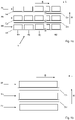
- Fig. 1a shows a sectional view of a belt 1 with three RodPack layers 2a, 2b, 2c and two fabric or scrim layers 3a, 3b arranged between adjacent Pultrudat or RodPack layers 2a, 2b, 2c.
- the number is only mentioned as an example, there are usually more RodPack layers, about 20 to 40 RodPack layers 2a, 2b, 2c provided.
- the fabric or scrim layers 3a, 3b can be provided between all adjacent RodPack layers 2a, 2b, 2c or only between a few adjacent RodPack layers 2a, 2b, 2c,
- the RodPack layers 2a, 2b, 2c are each a plurality, in 1 by exactly four rods 4a, 4b, 4c, 4d arranged next to one another and parallel to one another, each of which has a rectangular cross-section and here preferably has a width of 7 mm and a height of 2 mm.
- the rods 4a, 4b, 4c, 4d of a rod package 2a, 2b, 2c are glued to a preferably continuous carrier fleece 5a, 5b, 5c.
- the pultrudates 4a, 4b, 4c, 4d and the carrier fleece 5a, 5b, 5c together form a rod package layer 2a, 2b, 2c.
- the RodPack layers 2a, 2b, 2c are flexible perpendicularly to the longitudinal direction L and perpendicularly to the width B along the height H, so that they can be transported wound up on a roll.
- the RodPack layers 2a, 2b, 2c are cut to the required length and laid one on top of the other along the height H. Between adjacent RodPack layers 2a, 2b, 2c is in 1 in each case a fabric or scrim layer 3a, 3b is arranged.
- the RodPack layers 2a, 2b, 2c naturally have the longitudinal direction L, which corresponds to the longitudinal direction L of the individual rods 4a, 4b, 4c, 4d.
- the RodPack layers 2a, 2b, 2c have a high tensile strength in the longitudinal direction L, while the RodPack layers 2a, 2b, 2c have a low resistance to transverse forces, i.e. forces that are perpendicular to the longitudinal direction L along the width B or height H push or pull on the RodPack layers 2a, 2b, 2c.
- Perpendicular to the longitudinal direction L the RodPack layers 2a, 2b, 2c only have a tensile strength that is lower by a factor of approx. 10-30 than the tensile strength of the RodPack layers in the longitudinal direction L.
- the high tensile strength of the RodPack layers 2a, 2b, 2c in the longitudinal direction L is due to the fact that the rods 4a, 4b, 4c, 4d themselves have a significantly higher tensile strength in the longitudinal direction L than a transverse tensile strength along the width B and also along the height H, since the fibers that essentially form the rods are also aligned in the longitudinal direction L.
- the strength of the rods in the transverse direction B, H is solely due to the The strength of the resin matrix is determined because there are no fibers in the rod and therefore in the RodPack in this direction.
- the rods 4a, 4b, 4c, 4d used here are produced in a pultrusion process, in which case rovings are essentially laminated together.
- the rovings can be bundles of glass fibers or carbon fibers or mixtures thereof or other fibers, which are drawn off simultaneously from rolls arranged next to one another.
- the rovings are laminated together in a pultrusion process and shaped as rods 4a, 4b, 4c, 4d with a rectangular cross-section and the above-mentioned dimensions, and then cut to the required length.
- RodPack layers 2a, 2b, 2c can be rolled up and transported and processed more easily as rolled goods.
- Figure 1 shows the cross-section of the belt according to the invention when made with a pultrudate.
- the pultrudate plate has the same width as the desired belt.
- narrower pultrudate plates can also be used, which then lie next to one another, preferably no more than 4 plates next to one another.
- everything above applies to the example of the Figure 1a also explained for the embodiment of a belt according to the invention made of pultrudate.
- the invention is characterized in one of its aspects by the fact that according to Figure 2a in the region of the root-side end of the RodPack layers, at least one fabric or scrim layer 3a, 3b is applied to a RodPack layer 2a, 2b, 2c. While the fibers of the RodPack layers 2a, 2b, 2c have a longitudinal direction L determined by the orientation of the pultrudate, the fabric or non-crimp fabric layers 3a, 3b have two main fiber directions H1, H2 here, which are defined by the directions of the interwoven or one upon the other sewn fibers are formed.
- the main fiber direction H1, H2 is understood here to mean the two fiber directions along whose directions the majority of the fibers of the respective fabric or scrim layers 3a, 3b are aligned, but this does not change the fact that a smaller number of fibers cannot run along the main fiber directions . However, at least 30%, but preferably at least 40% of the fibers run along each of the two main fiber directions H1, H2.
- a Fabric layer 3a, 3b two, three or a plurality of fabric layers 3a, 3b can also be provided between two RodPack layers 2a, 2b, 2c. All statements in this chapter also apply if the belt according to the invention is manufactured with pultrudate panels, as described above.
- the invention is characterized in one of its aspects Figure 2b in the area of the tip-side end of the pultrudat or rod pack layers 2a, 2b, 2c in that the pultrudat or rod pack layers 2a, 2b, 2c are lengthened by scrim layers 3a, 3b, 3c in the direction of the tip-side end of the belt and in that the pultrudat or rod pack layers have a bevel at their tip-side end, which ensures a smooth transition of the scrim layers 3a, 3b, 3c from the pultrudate or rod pack layers 2a, 2b, 2c and beyond their end.
- a scrim layer in this area of the belt according to the invention is characterized by a single main fiber direction H1, along which about 90% of the fibers are aligned, while a significantly smaller amount of transverse fibers in direction B of the belt is less than 10%, preferably less than 5% is intended to hold the fibers of the single main fiber direction H1 together and to provide scrim layer 3a, 3b, 3c with sufficient stability for handling.
- rod pack layers 2a, 2b, 2c and a fabric or scrim layer 3a, 3b, 3c are shown.
- further rod pack layers 2 can be provided alternating with further fabric layers 3 on the fabric layer 3a or 3c.
- the number of RodPack 2a, 2b, 2c and fabric layers 3a, 3b can be more than 20, preferably more than 30, particularly preferably more than 40 layers.
- the number of RodPack layers 2a, 2b, 2c is not limited but is adapted to the requirements of the rotor blade into which the belt 1 is installed.
- a ⁇ 45° fabric layer 3c with two main fiber directions H1, H2 is arranged in such a way that the two main fiber directions H1, H2 are arranged at an angle of 45° or an angle of -45° to the longitudinal direction L.
- the arrangement can be transferred to a belt 1 with a plurality of RodPack layers 2a, 2b, 2c and fabric layers 3a, 3b.
- the fabric itself has two main fiber directions H1, H2, which do not have an angle of 90° relative to one another, but for example an angle of 120°, so that the main fiber directions H1, H2 can be aligned at an angle of 60° or at an angle of -60° to the longitudinal direction L.
- the fabric layers 3a, 3b give the belt 1 a significantly increased transverse tensile strength compared to a belt 1 that consists of directly stacked, touching Pultrudate or RodPack layers 2a, 2b, 2c.
- FIG. 1 shows, in another aspect of the invention, an end portion of the belt 1 in 1 .
- the end section is to be understood here as the end of the belt on the tip side.
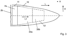
- the 3 shows the top view of the tip-side end of a rotor blade shell, the outer contour 10 of the finished blade shell, the outer contour 11 of the Pulturdate or RodPack layers 2a, 2b and the part of the contour 12 of the UD layer 30a, 30b, which on the tip side over the Pulturdate or RodPack layers 2a, 2b protrude.
- 2 layers of Pultrudate or RodPack layers 2a, 2b are shown as examples, which are each extended from a UD layer 30a, 30b in the direction of the tip.
- the belt according to the invention is not limited to 2 Pultrudate or RodPack layers, which are lengthened in the direction of the tip; in principle, any number of Pultrudate or RodPack layers can be lengthened in the direction of the tip.
- the pultrudate or RodPack layers 2a, 2b, 2c are provided as rolled goods and are cut to a length determined by the length of the rotor blade. However, it is difficult to seam the Pultrudate or RodPack layers 2a, 2b, 2c, i.e. to narrow them in width.
- the belts 1 In the tip area of the rotor blade, the belts 1 must taper and be narrower than in the root area or in the aerodynamic area of the rotor blade so that they can project into the outermost tip.
- the RodPack layers 2a, 2b are cut to a length in which they can still be applied to the inside of the rotor blade shell without tapering, i.e. trimming in the interior of the rotor blade. while the strap 1 in the direction of the tip from the end of the strap into the tip through UD layers 30a, 30b (unidirectional layers) is continued.
- the UD layers 30a, 30b are woven or non-crimp fabric layers with a single main fiber direction L1.
- the main fiber direction L1 is characterized in that approximately 90%, preferably over 95%, of the fibers run along this direction.
- the main fiber direction L1 is aligned in the longitudinal direction L.
- the UD layers 30a, 30b run towards the root end of the belt 1 between the RodPack layers 2a, 2b. It is conceivable that the UD layers 30a, 30b start at the outermost, root end of the belt 1 , extend over the entire length of the RodPack layers 2a, 2b and are extended beyond the RodPack layers 2a, 2b at the end of the RodPack layers 2a, 2b on the tip side.
- the belt 1 can be produced very easily, particularly in the area of the end of the belt 1 on the tip side.
- the belt 1 can be manufactured separately.
- the above-described pultrudate or RodPack layers 2a, 2b, 2c and fabric or scrim layers 3a, 3b, 30a, 30b are first layered on top of one another or next to one another in the appropriate production form.
- z. B. carried out an infusion process in which between the pultrudate or RodPack layers 2a, 2b, 2c and in the fabric or scrim layers 3a, 3b, 30a, 30b and possibly in the spaces between the rods 4a, 4b , 4c, 4d of the RodPack layers 2a, 2b, 2c a resin system is infused.
- chord 1 is first manufactured separately, e.g. B. using an infusion process, while in the second variant the semi-finished product of the belt 1 is placed with the semi-finished product of the rotor blade half-shell and then the semi-finished product of the rotor blade half-shell including the semi-finished product of the belt 1 is laminated together in an infusion process. Irrespective of the choice of variant, the semi-finished product is placed in a production device.
- the semi-finished product layered one on top of the other in the production device is then sealed with a vacuum film on the inside of the mold shell, ie a vacuum film is placed on the semi-finished product and the vacuum film is sealed at the edges of the production half-shell.
- a preferably two-component resin system is then infused into the semi-finished product via feed and discharge lines, and first air and, after the semi-finished product has been impregnated with the resin system, excess liquid resin system is sucked out of the semi-finished product via discharge lines. if the semi-finished product is completely saturated with resin, the curing process starts in the form of an exothermic chemical reaction.
- the belt 1 according to the invention is essentially straight in the longitudinal direction L due to the use of Pultrudate or RodPacks, so that the belt 1 according to the invention is primarily a main belt that runs in the longitudinal direction L along the inner wall of a half-shell of a rotor blade and is glued on there .
- the method for a trailing edge chord for example the chord 1 could not be prefabricated over the entire length of the rotor blade, but straight sections of the trailing edge chord could be prefabricated and then integrated piece by piece in the rotor blade half shell.
Landscapes
- Chemical & Material Sciences (AREA)
- Engineering & Computer Science (AREA)
- Composite Materials (AREA)
- Mechanical Engineering (AREA)
- Moulding By Coating Moulds (AREA)
Applications Claiming Priority (2)
| Application Number | Priority Date | Filing Date | Title |
|---|---|---|---|
| DE102016009640.3A DE102016009640A1 (de) | 2016-08-10 | 2016-08-10 | Gurt aus vorgefertigten Elementen mit Gelege und ein Verfahren zu seiner Fertigung |
| PCT/EP2017/070156 WO2018029240A1 (de) | 2016-08-10 | 2017-08-09 | Gurt aus vorgefertigten elementen mit gelege und ein verfahren zu seiner fertigung |
Publications (2)
| Publication Number | Publication Date |
|---|---|
| EP3496936A1 EP3496936A1 (de) | 2019-06-19 |
| EP3496936B1 true EP3496936B1 (de) | 2022-11-30 |
Family
ID=59581930
Family Applications (1)
| Application Number | Title | Priority Date | Filing Date |
|---|---|---|---|
| EP17751381.9A Active EP3496936B1 (de) | 2016-08-10 | 2017-08-09 | Gurt aus vorgefertigten elementen mit gelege und ein verfahren zu seiner fertigung |
Country Status (7)
| Country | Link |
|---|---|
| EP (1) | EP3496936B1 (pt) |
| CN (1) | CN109641409B (pt) |
| DE (1) | DE102016009640A1 (pt) |
| DK (1) | DK3496936T3 (pt) |
| ES (1) | ES2937720T3 (pt) |
| PT (1) | PT3496936T (pt) |
| WO (1) | WO2018029240A1 (pt) |
Families Citing this family (12)
| Publication number | Priority date | Publication date | Assignee | Title |
|---|---|---|---|---|
| DE102018006085A1 (de) * | 2018-08-02 | 2020-02-06 | Senvion Gmbh | Verjüngter Pultrudatgurt und ein Verfahren zu seiner Herstellung |
| US10895244B2 (en) * | 2018-09-25 | 2021-01-19 | General Electric Company | Joint interface for wind turbine rotor blade components |
| EP3874140A1 (en) | 2018-11-01 | 2021-09-08 | General Electric Company | Scarf connection for a wind turbine rotor blade |
| DE102018009338A1 (de) * | 2018-11-28 | 2020-05-28 | Senvion Gmbh | Rotorblattkomponente, Verfahren zu deren Herstellung und Windenergieanlage |
| DE102018009332A1 (de) * | 2018-11-28 | 2020-05-28 | Senvion Gmbh | Rotorblatt mit Gurten mit verformbaren Pultrudaten |
| DE102019000052A1 (de) * | 2019-01-08 | 2020-07-09 | Senvion Gmbh | Rotorblatt mit wenigstens einem Gurt mit einer Mehrzahl an Pultrudaten und ein Verfahren zu seiner Herstellung |
| DK180532B1 (en) | 2019-04-23 | 2021-06-10 | Envision Energy Denmark Aps | A WIND WINDOW WING AND A METHOD FOR MANUFACTURING THE WIND WIND WING |
| US11131290B2 (en) | 2019-06-25 | 2021-09-28 | General Electric Company | Scarf connection for a wind turbine rotor blade |
| WO2021219751A1 (en) * | 2020-04-28 | 2021-11-04 | Lm Wind Power A/S | Optimized spar cap structure for wind turbine blade |
| US20230072647A1 (en) * | 2020-04-28 | 2023-03-09 | Lm Wind Power A/S | Optimized interlayer for a spar cap for a wind turbine blade |
| EP4108439A1 (en) * | 2021-06-25 | 2022-12-28 | LM Wind Power A/S | Spar cap with tapering and serrated end section |
| CN113339188B (zh) * | 2021-06-29 | 2024-04-09 | 三一重能股份有限公司 | 一种风电叶片主梁结构及其制备方法和风电叶片 |
Citations (5)
| Publication number | Priority date | Publication date | Assignee | Title |
|---|---|---|---|---|
| US20070140862A1 (en) | 2005-12-20 | 2007-06-21 | Rolls-Royce Plc | Lightweight components |
| WO2011135306A1 (en) | 2010-04-30 | 2011-11-03 | Blade Dynamics Limited | A modular structural composite beam |
| US20150151390A1 (en) | 2010-01-14 | 2015-06-04 | Neptco, Inc. | Wind turbine rotor blade components and machine for making same |
| WO2016015736A1 (en) | 2014-07-31 | 2016-02-04 | Vestas Wind Systems A/S | Improvements relating to reinforcing structures for wind turbine blades |
| EP3034865A1 (de) | 2014-12-16 | 2016-06-22 | Senvion GmbH | Anordnung pultrudierter stäbe |
Family Cites Families (9)
| Publication number | Priority date | Publication date | Assignee | Title |
|---|---|---|---|---|
| DK176564B1 (da) * | 2004-12-29 | 2008-09-01 | Lm Glasfiber As | Fiberforstærket samling |
| DE102008055771C5 (de) | 2008-11-04 | 2018-06-14 | Senvion Gmbh | Rotorblattgurt |
| DE102011003560B4 (de) | 2011-02-03 | 2013-08-29 | Repower Systems Se | Verfahren zum Herstellen eines Faserhalbzeugs für die Herstellung eines faserverstärkten Bauteils einer Windenergieanlage, insbesondere Rotorblattgurt, sowie Faserhalbzeug und Verwendung eines Faserhalbzeugs |
| US20120027609A1 (en) * | 2011-05-17 | 2012-02-02 | Prasad Ogde | Wind turbine rotor blade with precured fiber rods and method for producing the same |
| WO2012161741A2 (en) * | 2011-05-24 | 2012-11-29 | Edwards Christopher M | Wind blade spar caps |
| CN102705157A (zh) * | 2012-06-21 | 2012-10-03 | 张向增 | 一种水平轴风力发电机叶片及其成型方法和设备 |
| DE102012219226A1 (de) * | 2012-10-22 | 2014-04-24 | Repower Systems Se | Vorrichtung und Verfahren zur Herstellung eines Rotorblattgurts |
| GB2526795A (en) * | 2014-06-02 | 2015-12-09 | Vestas Wind Sys As | Wind turbines incorporating radar absorbing material |
| CN105465141B (zh) * | 2016-01-05 | 2017-11-21 | 中复碳芯电缆科技有限公司 | 一种风力发电机叶片用拉挤预埋叶根连接件及其制备方法 |
-
2016
- 2016-08-10 DE DE102016009640.3A patent/DE102016009640A1/de not_active Withdrawn
-
2017
- 2017-08-09 DK DK17751381.9T patent/DK3496936T3/da active
- 2017-08-09 EP EP17751381.9A patent/EP3496936B1/de active Active
- 2017-08-09 PT PT177513819T patent/PT3496936T/pt unknown
- 2017-08-09 CN CN201780047707.XA patent/CN109641409B/zh active Active
- 2017-08-09 ES ES17751381T patent/ES2937720T3/es active Active
- 2017-08-09 WO PCT/EP2017/070156 patent/WO2018029240A1/de unknown
Patent Citations (5)
| Publication number | Priority date | Publication date | Assignee | Title |
|---|---|---|---|---|
| US20070140862A1 (en) | 2005-12-20 | 2007-06-21 | Rolls-Royce Plc | Lightweight components |
| US20150151390A1 (en) | 2010-01-14 | 2015-06-04 | Neptco, Inc. | Wind turbine rotor blade components and machine for making same |
| WO2011135306A1 (en) | 2010-04-30 | 2011-11-03 | Blade Dynamics Limited | A modular structural composite beam |
| WO2016015736A1 (en) | 2014-07-31 | 2016-02-04 | Vestas Wind Systems A/S | Improvements relating to reinforcing structures for wind turbine blades |
| EP3034865A1 (de) | 2014-12-16 | 2016-06-22 | Senvion GmbH | Anordnung pultrudierter stäbe |
Non-Patent Citations (4)
| Title |
|---|
| "ASM Handbook", 1 January 2001, article MARTIN JEFFREY D., JOSEPH E. SUMEREK: "Pultrution", pages: 533 - 243, XP093112960 |
| "Pultrusion for engineers", 1 January 2000, WOODHEAD PUBLISHING LIMITED, article ADAMS DAVID F., JAMES V. GAUCHET, LUC PETERS, TREVOR F. SYARR: "3 Profile design, specification, properties and related matters. 5 Reinforcements for pultrusion", pages: 67 - 96, 175-196, XP093112956 |
| GARDINER GINGER: "Blade cycle time: 37 percent faster", CW COMPOSITES WORLD, 2 January 2012 (2012-01-02), XP093112955, Retrieved from the Internet <URL:https://www.compositesworld.com/articles/blade-cycle-time-37-percent-faster#:~:text=Collectively%2C%20however%2C%20they%20have%20reduced,cycle%20time%20by%2035%20percent.> [retrieved on 20231218] |
| GRUHN JOEL, NARASIMHAN KAMESH: "RodPack: A New Form of Aligned Fiber Reinforcement for Wind Blade Spar Caps", 2012 WIND TURBINE BLADE WORKSHOP NEPTCO INCORPORATED SANDIA NATIONAL LABORATORIES, 1 January 2012 (2012-01-01), pages 1 - 26, XP093112954, Retrieved from the Internet <URL:https://energy.sandia.gov/wp-content//gallery/uploads/2A-B-2-Gruhn1.pdf> [retrieved on 20231218] |
Also Published As
| Publication number | Publication date |
|---|---|
| EP3496936A1 (de) | 2019-06-19 |
| WO2018029240A1 (de) | 2018-02-15 |
| PT3496936T (pt) | 2023-02-13 |
| DE102016009640A1 (de) | 2018-02-15 |
| ES2937720T3 (es) | 2023-03-30 |
| DK3496936T3 (da) | 2023-01-23 |
| CN109641409B (zh) | 2022-02-18 |
| CN109641409A (zh) | 2019-04-16 |
Similar Documents
| Publication | Publication Date | Title |
|---|---|---|
| EP3496936B1 (de) | Gurt aus vorgefertigten elementen mit gelege und ein verfahren zu seiner fertigung | |
| EP2904262B1 (de) | Faserverbundbauteil für das rotorblatt einer windturbine | |
| EP2363599B2 (de) | Rotorblatt für eine Windenergieanlage, Windenergieanlage und Verfahren zum Herstellen eines Rotorblatts | |
| EP2046564B1 (de) | Verfahren zur Herstellung von mehreren Faserverbundbauteilen | |
| DE2611235C2 (de) | Rotorblatt für Drehflügler, insbesondere Hubschrauber | |
| AT398064B (de) | Kunststoff-verbundprofil, insbesondere flügelholm für den flugzeugbau | |
| DE102008019070B3 (de) | Verfahren zur Herstellung eines beidseitig mit Deckschichten versehenen Kernverbundes | |
| DE3534293A1 (de) | Einrichtung zur verringerung des reibungswiderstandes | |
| DE102008028865B4 (de) | Verfahren zur Herstellung von Faserverbund-Profilbauteilen, sowie Verwendung derartig hergestellter Faserverbund-Profilbauteile | |
| WO2009098088A2 (de) | Verfahren zur herstellung eines fvw-bauteils, fvw-bauteil sowie ein fvw-rumpfteil eines flugzeugs | |
| AT400954B (de) | Gewebe, prepreg aus diesem gewebe, leichtbauteil aus derartigen prepregs, überkopf-gepäckablage für flugzeuge | |
| DE102011003560B4 (de) | Verfahren zum Herstellen eines Faserhalbzeugs für die Herstellung eines faserverstärkten Bauteils einer Windenergieanlage, insbesondere Rotorblattgurt, sowie Faserhalbzeug und Verwendung eines Faserhalbzeugs | |
| DE102015007289A1 (de) | Rotorblatt, Rotorblattgurt und Verfahren zum Herstellen eines Rotorblattgurts | |
| EP3127686B1 (de) | Verfahren zur herstellung eines bauteils eines rotorblattes einer windenergieanlage | |
| DE102017113769A1 (de) | Pultrudiertes Profil mit Abreißgewebe | |
| EP3551438B1 (de) | Hinterkantengurt eines rotorblatts einer windenergieanlage, rotorblatt und verfahren zum herstellen eines hinterkantengurts | |
| DE102017113757A1 (de) | Pultrudiertes Profil mit Abreißgewebe | |
| EP3360667A1 (de) | Rotorblatthinterkanten-verklebewinkel | |
| DE102017011737A1 (de) | Verfahren und System zum Betreiben einer Windenergieanlage | |
| EP3604797B1 (de) | Verjüngter pultrudatgurt und ein verfahren zu seiner herstellung | |
| DE102014221356B4 (de) | Baugruppe mit Einzelkomponenten aus einem faserverstärkten Verbundmaterial | |
| EP0261375B1 (de) | Verfahren zum Herstellen eines Faserverbund-Hohlträgers | |
| DE3003906A1 (de) | Verfahren zur herstellung hohler gegenstaende aus faserverstaerktem kunststoff | |
| DE102017126276A1 (de) | Verfahren zur Herstellung einer Steg-Gurt-Baugruppe für ein Windenergieanlagenrotorblatt und Steg-Gurt-Baugruppe | |
| EP3587801A1 (de) | Rotorblatt mit steg in wabensandwichbauweise |
Legal Events
| Date | Code | Title | Description |
|---|---|---|---|
| STAA | Information on the status of an ep patent application or granted ep patent |
Free format text: STATUS: UNKNOWN |
|
| STAA | Information on the status of an ep patent application or granted ep patent |
Free format text: STATUS: THE INTERNATIONAL PUBLICATION HAS BEEN MADE |
|
| PUAI | Public reference made under article 153(3) epc to a published international application that has entered the european phase |
Free format text: ORIGINAL CODE: 0009012 |
|
| STAA | Information on the status of an ep patent application or granted ep patent |
Free format text: STATUS: REQUEST FOR EXAMINATION WAS MADE |
|
| 17P | Request for examination filed |
Effective date: 20190207 |
|
| AK | Designated contracting states |
Kind code of ref document: A1 Designated state(s): AL AT BE BG CH CY CZ DE DK EE ES FI FR GB GR HR HU IE IS IT LI LT LU LV MC MK MT NL NO PL PT RO RS SE SI SK SM TR |
|
| AX | Request for extension of the european patent |
Extension state: BA ME |
|
| DAV | Request for validation of the european patent (deleted) | ||
| DAX | Request for extension of the european patent (deleted) | ||
| RAP1 | Party data changed (applicant data changed or rights of an application transferred) |
Owner name: SIEMENS GAMESA RENEWABLE ENERGY SERVICE GMBH |
|
| STAA | Information on the status of an ep patent application or granted ep patent |
Free format text: STATUS: EXAMINATION IS IN PROGRESS |
|
| 17Q | First examination report despatched |
Effective date: 20220217 |
|
| GRAP | Despatch of communication of intention to grant a patent |
Free format text: ORIGINAL CODE: EPIDOSNIGR1 |
|
| STAA | Information on the status of an ep patent application or granted ep patent |
Free format text: STATUS: GRANT OF PATENT IS INTENDED |
|
| INTG | Intention to grant announced |
Effective date: 20220825 |
|
| GRAS | Grant fee paid |
Free format text: ORIGINAL CODE: EPIDOSNIGR3 |
|
| GRAA | (expected) grant |
Free format text: ORIGINAL CODE: 0009210 |
|
| STAA | Information on the status of an ep patent application or granted ep patent |
Free format text: STATUS: THE PATENT HAS BEEN GRANTED |
|
| AK | Designated contracting states |
Kind code of ref document: B1 Designated state(s): AL AT BE BG CH CY CZ DE DK EE ES FI FR GB GR HR HU IE IS IT LI LT LU LV MC MK MT NL NO PL PT RO RS SE SI SK SM TR |
|
| REG | Reference to a national code |
Ref country code: CH Ref legal event code: EP Ref country code: GB Ref legal event code: FG4D Free format text: NOT ENGLISH |
|
| REG | Reference to a national code |
Ref country code: AT Ref legal event code: REF Ref document number: 1534357 Country of ref document: AT Kind code of ref document: T Effective date: 20221215 |
|
| REG | Reference to a national code |
Ref country code: IE Ref legal event code: FG4D Free format text: LANGUAGE OF EP DOCUMENT: GERMAN |
|
| REG | Reference to a national code |
Ref country code: DE Ref legal event code: R096 Ref document number: 502017014161 Country of ref document: DE |
|
| REG | Reference to a national code |
Ref country code: DK Ref legal event code: T3 Effective date: 20230120 |
|
| REG | Reference to a national code |
Ref country code: PT Ref legal event code: SC4A Ref document number: 3496936 Country of ref document: PT Date of ref document: 20230213 Kind code of ref document: T Free format text: AVAILABILITY OF NATIONAL TRANSLATION Effective date: 20230206 |
|
| REG | Reference to a national code |
Ref country code: LT Ref legal event code: MG9D |
|
| REG | Reference to a national code |
Ref country code: ES Ref legal event code: FG2A Ref document number: 2937720 Country of ref document: ES Kind code of ref document: T3 Effective date: 20230330 |
|
| REG | Reference to a national code |
Ref country code: NL Ref legal event code: MP Effective date: 20221130 |
|
| PG25 | Lapsed in a contracting state [announced via postgrant information from national office to epo] |
Ref country code: SE Free format text: LAPSE BECAUSE OF FAILURE TO SUBMIT A TRANSLATION OF THE DESCRIPTION OR TO PAY THE FEE WITHIN THE PRESCRIBED TIME-LIMIT Effective date: 20221130 Ref country code: NO Free format text: LAPSE BECAUSE OF FAILURE TO SUBMIT A TRANSLATION OF THE DESCRIPTION OR TO PAY THE FEE WITHIN THE PRESCRIBED TIME-LIMIT Effective date: 20230228 Ref country code: LT Free format text: LAPSE BECAUSE OF FAILURE TO SUBMIT A TRANSLATION OF THE DESCRIPTION OR TO PAY THE FEE WITHIN THE PRESCRIBED TIME-LIMIT Effective date: 20221130 Ref country code: FI Free format text: LAPSE BECAUSE OF FAILURE TO SUBMIT A TRANSLATION OF THE DESCRIPTION OR TO PAY THE FEE WITHIN THE PRESCRIBED TIME-LIMIT Effective date: 20221130 |
|
| PG25 | Lapsed in a contracting state [announced via postgrant information from national office to epo] |
Ref country code: RS Free format text: LAPSE BECAUSE OF FAILURE TO SUBMIT A TRANSLATION OF THE DESCRIPTION OR TO PAY THE FEE WITHIN THE PRESCRIBED TIME-LIMIT Effective date: 20221130 Ref country code: PL Free format text: LAPSE BECAUSE OF FAILURE TO SUBMIT A TRANSLATION OF THE DESCRIPTION OR TO PAY THE FEE WITHIN THE PRESCRIBED TIME-LIMIT Effective date: 20221130 Ref country code: LV Free format text: LAPSE BECAUSE OF FAILURE TO SUBMIT A TRANSLATION OF THE DESCRIPTION OR TO PAY THE FEE WITHIN THE PRESCRIBED TIME-LIMIT Effective date: 20221130 Ref country code: IS Free format text: LAPSE BECAUSE OF FAILURE TO SUBMIT A TRANSLATION OF THE DESCRIPTION OR TO PAY THE FEE WITHIN THE PRESCRIBED TIME-LIMIT Effective date: 20230330 Ref country code: HR Free format text: LAPSE BECAUSE OF FAILURE TO SUBMIT A TRANSLATION OF THE DESCRIPTION OR TO PAY THE FEE WITHIN THE PRESCRIBED TIME-LIMIT Effective date: 20221130 Ref country code: GR Free format text: LAPSE BECAUSE OF FAILURE TO SUBMIT A TRANSLATION OF THE DESCRIPTION OR TO PAY THE FEE WITHIN THE PRESCRIBED TIME-LIMIT Effective date: 20230301 |
|
| PG25 | Lapsed in a contracting state [announced via postgrant information from national office to epo] |
Ref country code: NL Free format text: LAPSE BECAUSE OF FAILURE TO SUBMIT A TRANSLATION OF THE DESCRIPTION OR TO PAY THE FEE WITHIN THE PRESCRIBED TIME-LIMIT Effective date: 20221130 |
|
| PG25 | Lapsed in a contracting state [announced via postgrant information from national office to epo] |
Ref country code: SM Free format text: LAPSE BECAUSE OF FAILURE TO SUBMIT A TRANSLATION OF THE DESCRIPTION OR TO PAY THE FEE WITHIN THE PRESCRIBED TIME-LIMIT Effective date: 20221130 Ref country code: RO Free format text: LAPSE BECAUSE OF FAILURE TO SUBMIT A TRANSLATION OF THE DESCRIPTION OR TO PAY THE FEE WITHIN THE PRESCRIBED TIME-LIMIT Effective date: 20221130 Ref country code: EE Free format text: LAPSE BECAUSE OF FAILURE TO SUBMIT A TRANSLATION OF THE DESCRIPTION OR TO PAY THE FEE WITHIN THE PRESCRIBED TIME-LIMIT Effective date: 20221130 Ref country code: CZ Free format text: LAPSE BECAUSE OF FAILURE TO SUBMIT A TRANSLATION OF THE DESCRIPTION OR TO PAY THE FEE WITHIN THE PRESCRIBED TIME-LIMIT Effective date: 20221130 |
|
| REG | Reference to a national code |
Ref country code: DE Ref legal event code: R026 Ref document number: 502017014161 Country of ref document: DE |
|
| PG25 | Lapsed in a contracting state [announced via postgrant information from national office to epo] |
Ref country code: SK Free format text: LAPSE BECAUSE OF FAILURE TO SUBMIT A TRANSLATION OF THE DESCRIPTION OR TO PAY THE FEE WITHIN THE PRESCRIBED TIME-LIMIT Effective date: 20221130 Ref country code: AL Free format text: LAPSE BECAUSE OF FAILURE TO SUBMIT A TRANSLATION OF THE DESCRIPTION OR TO PAY THE FEE WITHIN THE PRESCRIBED TIME-LIMIT Effective date: 20221130 |
|
| PLBI | Opposition filed |
Free format text: ORIGINAL CODE: 0009260 |
|
| PLAX | Notice of opposition and request to file observation + time limit sent |
Free format text: ORIGINAL CODE: EPIDOSNOBS2 |
|
| 26 | Opposition filed |
Opponent name: LM WIND POWER A/S Effective date: 20230825 |
|
| PGFP | Annual fee paid to national office [announced via postgrant information from national office to epo] |
Ref country code: IT Payment date: 20230831 Year of fee payment: 7 Ref country code: GB Payment date: 20230824 Year of fee payment: 7 Ref country code: ES Payment date: 20230918 Year of fee payment: 7 |
|
| PG25 | Lapsed in a contracting state [announced via postgrant information from national office to epo] |
Ref country code: SI Free format text: LAPSE BECAUSE OF FAILURE TO SUBMIT A TRANSLATION OF THE DESCRIPTION OR TO PAY THE FEE WITHIN THE PRESCRIBED TIME-LIMIT Effective date: 20221130 |
|
| PGFP | Annual fee paid to national office [announced via postgrant information from national office to epo] |
Ref country code: PT Payment date: 20230731 Year of fee payment: 7 Ref country code: FR Payment date: 20230821 Year of fee payment: 7 Ref country code: DK Payment date: 20230823 Year of fee payment: 7 Ref country code: DE Payment date: 20230822 Year of fee payment: 7 |
|
| PLBB | Reply of patent proprietor to notice(s) of opposition received |
Free format text: ORIGINAL CODE: EPIDOSNOBS3 |
|
| PG25 | Lapsed in a contracting state [announced via postgrant information from national office to epo] |
Ref country code: MC Free format text: LAPSE BECAUSE OF FAILURE TO SUBMIT A TRANSLATION OF THE DESCRIPTION OR TO PAY THE FEE WITHIN THE PRESCRIBED TIME-LIMIT Effective date: 20221130 |
|
| REG | Reference to a national code |
Ref country code: CH Ref legal event code: PL |
|
| PG25 | Lapsed in a contracting state [announced via postgrant information from national office to epo] |
Ref country code: MC Free format text: LAPSE BECAUSE OF FAILURE TO SUBMIT A TRANSLATION OF THE DESCRIPTION OR TO PAY THE FEE WITHIN THE PRESCRIBED TIME-LIMIT Effective date: 20221130 |
|
| PG25 | Lapsed in a contracting state [announced via postgrant information from national office to epo] |
Ref country code: LU Free format text: LAPSE BECAUSE OF NON-PAYMENT OF DUE FEES Effective date: 20230809 |
|
| PG25 | Lapsed in a contracting state [announced via postgrant information from national office to epo] |
Ref country code: LU Free format text: LAPSE BECAUSE OF NON-PAYMENT OF DUE FEES Effective date: 20230809 Ref country code: CH Free format text: LAPSE BECAUSE OF NON-PAYMENT OF DUE FEES Effective date: 20230831 |
|
| REG | Reference to a national code |
Ref country code: BE Ref legal event code: MM Effective date: 20230831 |
|
| REG | Reference to a national code |
Ref country code: IE Ref legal event code: MM4A |