EP3496321B1 - Pilotsignalübertragungs-/empfangs-verfahren, endgeräteausrüstung und netzwerkausrüstung - Google Patents
Pilotsignalübertragungs-/empfangs-verfahren, endgeräteausrüstung und netzwerkausrüstung Download PDFInfo
- Publication number
- EP3496321B1 EP3496321B1 EP17845276.9A EP17845276A EP3496321B1 EP 3496321 B1 EP3496321 B1 EP 3496321B1 EP 17845276 A EP17845276 A EP 17845276A EP 3496321 B1 EP3496321 B1 EP 3496321B1
- Authority
- EP
- European Patent Office
- Prior art keywords
- pilot
- target
- terminal device
- pilots
- group
- Prior art date
- Legal status (The legal status is an assumption and is not a legal conclusion. Google has not performed a legal analysis and makes no representation as to the accuracy of the status listed.)
- Active
Links
Images


Classifications
-
- H—ELECTRICITY
- H04—ELECTRIC COMMUNICATION TECHNIQUE
- H04L—TRANSMISSION OF DIGITAL INFORMATION, e.g. TELEGRAPHIC COMMUNICATION
- H04L5/00—Arrangements affording multiple use of the transmission path
- H04L5/003—Arrangements for allocating sub-channels of the transmission path
- H04L5/0048—Allocation of pilot signals, i.e. of signals known to the receiver
- H04L5/0051—Allocation of pilot signals, i.e. of signals known to the receiver of dedicated pilots, i.e. pilots destined for a single user or terminal
-
- H—ELECTRICITY
- H04—ELECTRIC COMMUNICATION TECHNIQUE
- H04L—TRANSMISSION OF DIGITAL INFORMATION, e.g. TELEGRAPHIC COMMUNICATION
- H04L5/00—Arrangements affording multiple use of the transmission path
- H04L5/003—Arrangements for allocating sub-channels of the transmission path
- H04L5/0048—Allocation of pilot signals, i.e. of signals known to the receiver
-
- H—ELECTRICITY
- H04—ELECTRIC COMMUNICATION TECHNIQUE
- H04L—TRANSMISSION OF DIGITAL INFORMATION, e.g. TELEGRAPHIC COMMUNICATION
- H04L25/00—Baseband systems
- H04L25/02—Details ; arrangements for supplying electrical power along data transmission lines
- H04L25/0202—Channel estimation
- H04L25/0224—Channel estimation using sounding signals
- H04L25/0226—Channel estimation using sounding signals sounding signals per se
-
- H—ELECTRICITY
- H04—ELECTRIC COMMUNICATION TECHNIQUE
- H04L—TRANSMISSION OF DIGITAL INFORMATION, e.g. TELEGRAPHIC COMMUNICATION
- H04L27/00—Modulated-carrier systems
- H04L27/0014—Carrier regulation
-
- H—ELECTRICITY
- H04—ELECTRIC COMMUNICATION TECHNIQUE
- H04L—TRANSMISSION OF DIGITAL INFORMATION, e.g. TELEGRAPHIC COMMUNICATION
- H04L27/00—Modulated-carrier systems
- H04L27/26—Systems using multi-frequency codes
- H04L27/2601—Multicarrier modulation systems
- H04L27/2602—Signal structure
- H04L27/26035—Maintenance of orthogonality, e.g. for signals exchanged between cells or users, or by using covering codes or sequences
-
- H—ELECTRICITY
- H04—ELECTRIC COMMUNICATION TECHNIQUE
- H04L—TRANSMISSION OF DIGITAL INFORMATION, e.g. TELEGRAPHIC COMMUNICATION
- H04L27/00—Modulated-carrier systems
- H04L27/26—Systems using multi-frequency codes
- H04L27/2601—Multicarrier modulation systems
- H04L27/2602—Signal structure
- H04L27/261—Details of reference signals
- H04L27/2613—Structure of the reference signals
-
- H—ELECTRICITY
- H04—ELECTRIC COMMUNICATION TECHNIQUE
- H04L—TRANSMISSION OF DIGITAL INFORMATION, e.g. TELEGRAPHIC COMMUNICATION
- H04L27/00—Modulated-carrier systems
- H04L27/26—Systems using multi-frequency codes
- H04L27/2601—Multicarrier modulation systems
- H04L27/2647—Arrangements specific to the receiver only
- H04L27/2655—Synchronisation arrangements
- H04L27/2657—Carrier synchronisation
-
- H—ELECTRICITY
- H04—ELECTRIC COMMUNICATION TECHNIQUE
- H04L—TRANSMISSION OF DIGITAL INFORMATION, e.g. TELEGRAPHIC COMMUNICATION
- H04L27/00—Modulated-carrier systems
- H04L27/26—Systems using multi-frequency codes
- H04L27/2601—Multicarrier modulation systems
- H04L27/2647—Arrangements specific to the receiver only
- H04L27/2655—Synchronisation arrangements
- H04L27/2666—Acquisition of further OFDM parameters, e.g. bandwidth, subcarrier spacing, or guard interval length
-
- H—ELECTRICITY
- H04—ELECTRIC COMMUNICATION TECHNIQUE
- H04L—TRANSMISSION OF DIGITAL INFORMATION, e.g. TELEGRAPHIC COMMUNICATION
- H04L27/00—Modulated-carrier systems
- H04L27/26—Systems using multi-frequency codes
- H04L27/2601—Multicarrier modulation systems
- H04L27/2647—Arrangements specific to the receiver only
- H04L27/2655—Synchronisation arrangements
- H04L27/2668—Details of algorithms
- H04L27/2673—Details of algorithms characterised by synchronisation parameters
- H04L27/2675—Pilot or known symbols
-
- H—ELECTRICITY
- H04—ELECTRIC COMMUNICATION TECHNIQUE
- H04L—TRANSMISSION OF DIGITAL INFORMATION, e.g. TELEGRAPHIC COMMUNICATION
- H04L5/00—Arrangements affording multiple use of the transmission path
- H04L5/003—Arrangements for allocating sub-channels of the transmission path
- H04L5/0048—Allocation of pilot signals, i.e. of signals known to the receiver
- H04L5/005—Allocation of pilot signals, i.e. of signals known to the receiver of common pilots, i.e. pilots destined for multiple users or terminals
-
- H—ELECTRICITY
- H04—ELECTRIC COMMUNICATION TECHNIQUE
- H04L—TRANSMISSION OF DIGITAL INFORMATION, e.g. TELEGRAPHIC COMMUNICATION
- H04L5/00—Arrangements affording multiple use of the transmission path
- H04L5/003—Arrangements for allocating sub-channels of the transmission path
- H04L5/0078—Timing of allocation
- H04L5/0082—Timing of allocation at predetermined intervals
-
- H—ELECTRICITY
- H04—ELECTRIC COMMUNICATION TECHNIQUE
- H04L—TRANSMISSION OF DIGITAL INFORMATION, e.g. TELEGRAPHIC COMMUNICATION
- H04L67/00—Network arrangements or protocols for supporting network services or applications
- H04L67/01—Protocols
- H04L67/12—Protocols specially adapted for proprietary or special-purpose networking environments, e.g. medical networks, sensor networks, networks in vehicles or remote metering networks
-
- H—ELECTRICITY
- H04—ELECTRIC COMMUNICATION TECHNIQUE
- H04W—WIRELESS COMMUNICATION NETWORKS
- H04W76/00—Connection management
- H04W76/20—Manipulation of established connections
- H04W76/27—Transitions between radio resource control [RRC] states
-
- H—ELECTRICITY
- H04—ELECTRIC COMMUNICATION TECHNIQUE
- H04W—WIRELESS COMMUNICATION NETWORKS
- H04W8/00—Network data management
- H04W8/005—Discovery of network devices, e.g. terminals
-
- H—ELECTRICITY
- H03—ELECTRONIC CIRCUITRY
- H03M—CODING; DECODING; CODE CONVERSION IN GENERAL
- H03M13/00—Coding, decoding or code conversion, for error detection or error correction; Coding theory basic assumptions; Coding bounds; Error probability evaluation methods; Channel models; Simulation or testing of codes
- H03M13/03—Error detection or forward error correction by redundancy in data representation, i.e. code words containing more digits than the source words
- H03M13/05—Error detection or forward error correction by redundancy in data representation, i.e. code words containing more digits than the source words using block codes, i.e. a predetermined number of check bits joined to a predetermined number of information bits
- H03M13/13—Linear codes
- H03M13/136—Reed-Muller [RM] codes
-
- H—ELECTRICITY
- H04—ELECTRIC COMMUNICATION TECHNIQUE
- H04J—MULTIPLEX COMMUNICATION
- H04J13/00—Code division multiplex systems
- H04J13/0007—Code type
- H04J13/0055—ZCZ [zero correlation zone]
- H04J13/0059—CAZAC [constant-amplitude and zero auto-correlation]
- H04J13/0062—Zadoff-Chu
-
- H—ELECTRICITY
- H04—ELECTRIC COMMUNICATION TECHNIQUE
- H04L—TRANSMISSION OF DIGITAL INFORMATION, e.g. TELEGRAPHIC COMMUNICATION
- H04L27/00—Modulated-carrier systems
- H04L27/26—Systems using multi-frequency codes
- H04L27/2601—Multicarrier modulation systems
- H04L27/2647—Arrangements specific to the receiver only
- H04L27/2655—Synchronisation arrangements
- H04L27/2668—Details of algorithms
- H04L27/2681—Details of algorithms characterised by constraints
- H04L27/2688—Resistance to perturbation, e.g. noise, interference or fading
-
- H—ELECTRICITY
- H04—ELECTRIC COMMUNICATION TECHNIQUE
- H04L—TRANSMISSION OF DIGITAL INFORMATION, e.g. TELEGRAPHIC COMMUNICATION
- H04L27/00—Modulated-carrier systems
- H04L27/26—Systems using multi-frequency codes
- H04L27/2601—Multicarrier modulation systems
- H04L27/2647—Arrangements specific to the receiver only
- H04L27/2655—Synchronisation arrangements
- H04L27/2689—Link with other circuits, i.e. special connections between synchronisation arrangements and other circuits for achieving synchronisation
- H04L27/2692—Link with other circuits, i.e. special connections between synchronisation arrangements and other circuits for achieving synchronisation with preamble design, i.e. with negotiation of the synchronisation sequence with transmitter or sequence linked to the algorithm used at the receiver
-
- H—ELECTRICITY
- H04—ELECTRIC COMMUNICATION TECHNIQUE
- H04L—TRANSMISSION OF DIGITAL INFORMATION, e.g. TELEGRAPHIC COMMUNICATION
- H04L5/00—Arrangements affording multiple use of the transmission path
- H04L5/0001—Arrangements for dividing the transmission path
- H04L5/0003—Two-dimensional division
- H04L5/0005—Time-frequency
- H04L5/0007—Time-frequency the frequencies being orthogonal, e.g. OFDM(A) or DMT
-
- H—ELECTRICITY
- H04—ELECTRIC COMMUNICATION TECHNIQUE
- H04L—TRANSMISSION OF DIGITAL INFORMATION, e.g. TELEGRAPHIC COMMUNICATION
- H04L5/00—Arrangements affording multiple use of the transmission path
- H04L5/0001—Arrangements for dividing the transmission path
- H04L5/0014—Three-dimensional division
- H04L5/0016—Time-frequency-code
-
- H—ELECTRICITY
- H04—ELECTRIC COMMUNICATION TECHNIQUE
- H04L—TRANSMISSION OF DIGITAL INFORMATION, e.g. TELEGRAPHIC COMMUNICATION
- H04L5/00—Arrangements affording multiple use of the transmission path
- H04L5/003—Arrangements for allocating sub-channels of the transmission path
- H04L5/0037—Inter-user or inter-terminal allocation
-
- H—ELECTRICITY
- H04—ELECTRIC COMMUNICATION TECHNIQUE
- H04L—TRANSMISSION OF DIGITAL INFORMATION, e.g. TELEGRAPHIC COMMUNICATION
- H04L5/00—Arrangements affording multiple use of the transmission path
- H04L5/0091—Signalling for the administration of the divided path, e.g. signalling of configuration information
Definitions
- This application relates to the communications field, and more specifically, to a pilot transmission/reception method, a terminal device, and a network device.
- Internet of Things Internet of Things
- MBB Mobile Broad Band
- MMC massive Machine communications
- MCC Mission Critical Communications
- a one-time transmission mode is usually used for the IoT services. That is, data transmission is completed in one transmission opportunity to avoid an access delay brought by scheduling.
- main functions of a pilot are user detection, channel estimation, frequency offset estimation, time offset estimation, and the like.
- a terminal device having data to be transmitted selects a pilot, and sends the data and the pilot together.
- a base station detects the pilot to determine a status of the terminal device; and if detecting that the terminal device is in an active state, performs channel estimation, frequency offset estimation, time offset estimation, and the like by using the pilot, and decodes data based on an estimation result.
- 3GPP TSG-RAN WG1 Meeting #86 R1-167698 discusses key design aspects for grant-less uplink non-orthogonal scheme, including resource partitioning, UE identification, preamble and DM-RS design, ACK response and retransmission, and contention based scheduling request.
- 3GPP TSG-RAN WG1 Meeting #86 R1-167126 discusses requirements and desired properties of waveforms for high frequency bands, and in details Guard Interval DFT-S-OFDM as a candidate waveform for high frequency bands.
- one slot has two symbols for carrying a pilot.
- the pilot in the slot is not only used by the base station to perform user detection but also used by the base station to perform frequency offset estimation. In this case, a frequency offset estimation result is inaccurate, leading to relatively poor transmission performance of an IoT service.
- This application provides a pilot transmission method, a pilot reception method, a terminal device and a network device according to the appended independent claims. Preferred embodiments and/or aspects are defined by the dependent claims.
- a component may be, but is not limited to, a process that runs on a processor, a processor, an object, an executable file, an executable thread, a program, and/or a computer.
- a computing device and an application that runs on a computing device may be components.
- One or more components may reside within a process and/or an executable thread, and a component may be located on one computer and/or distributed between two or more computers.
- these components may be executed from various computer-readable media that store various data structures.
- the components may communicate by using a local and/or remote process and according to, for example, a signal having one or more data packets (for example, data from two components interacting with another component in a local system, a distributed system, and/or across a network such as the Internet interacting with other systems by using the signal).
- a signal having one or more data packets (for example, data from two components interacting with another component in a local system, a distributed system, and/or across a network such as the Internet interacting with other systems by using the signal).
- the technical solutions in the embodiments of this application may be applied to a Long Term Evolution (Long Term Evolution, LTE) architecture, and may be further applied to a universal mobile telecommunications system (Universal Mobile Telecommunications System, UMTS) terrestrial radio access network (UMTS Terrestrial Radio Access Network, UTRAN) architecture, or a Global System for Mobile Communications (Global System for Mobile Communication, GSM)/enhanced data rate for GSM evolution (Enhanced Data Rate for GSM Evolution, EDGE) system radio access network (GSM EDGE Radio Access Network, GERAN) architecture.
- UMTS Universal Mobile Telecommunications System
- UTRAN Universal Mobile Telecommunications System
- GSM Global System for Mobile Communication
- GSM Global System for Mobile Communication
- EDGE Enhanced Data Rate for GSM Evolution
- GSM EDGE Radio Access Network, GERAN Global System for Mobile Communications
- GSM EDGE Radio Access Network GSM EDGE Radio Access Network
- a function of an MME is completed by a serving general packet radio service (General Packet Radio Service, GPRS) support node (Serving GPRS Support, SGSN), and a function of an SGW/PGW is completed by a gateway GPRS support node (Gateway GPRS Support Node, GGSN).
- GPRS General Packet Radio Service
- SGSN Serving GPRS Support
- GGSN gateway GPRS support node
- a terminal device is used in the embodiments of this application.
- the terminal device may be referred to as user equipment (User Equipment, UE), an access terminal, a subscriber unit, a subscriber station, a mobile station, a mobile console, a remote station, a remote terminal, a mobile device, a user terminal, a terminal, a wireless communications device, a user agent, or a user apparatus.
- UE user equipment
- UE User Equipment
- the access terminal may be a cellular phone, a cordless phone, a Session Initiation Protocol (Session Initiation Protocol, SIP) phone, a wireless local loop (Wireless Local Loop, WLL) station, a personal digital process (Personal Digital Assistant, PDA), a handheld device having a wireless communication function, a computing device, another processing device connected to a wireless modem, an in-vehicle device, a wearable device, or a terminal device in a future 5G network or a network later than 5G. This is not limited in the embodiments of this application.
- the terminal device may communicate with one or more core networks by using a radio access network (Radio Access Network, RAN), or may access a distributed point-to-point (Ad-Hoc) mode network in a self-organizing or license-free manner and a subnet deployed by a user.
- RAN Radio Access Network
- Ad-Hoc distributed point-to-point
- the terminal device may further access a network in another manner for communication. This is not limited in the embodiments of this application.
- the network device may be a device configured to communicate with the terminal device.
- the network device may be a base transceiver station (Base Transceiver Station, BTS) in a GSM system or a CDMA system, may be a NodeB (NodeB, NB) in a WCDMA system, or may be an evolved NodeB (Evolutional NodeB, eNB or eNodeB) in an LTE system.
- BTS Base Transceiver Station
- NodeB NodeB
- eNB evolved NodeB
- eNodeB evolved NodeB
- the network device may be a relay station, an access point, an in-vehicle device, a wearable device, a network side device in a future 5G network or a network later than 5G, a network device in a future evolved PLMN network, or the like.
- the network device in the embodiments of this application may be a network device in a cell, and may be a base station on a cell layer or a network device having a function similar to that of a base station.
- the network device may be a network device providing wireless access and communications services for a mobile or fixed terminal device in a cell.
- aspects or features of this application may be implemented as a method, an apparatus or a product that uses standard programming and/or engineering technologies.
- the term "product" used in this application covers a computer program that can be accessed from any computer-readable component, carrier or medium.
- the computer-readable medium may include but is not limited to: a magnetic storage component (for example, a hard disk, a floppy disk or a magnetic tape), an optical disc (for example, a compact disc (Compact Disk, CD), a digital versatile disc (Digital Versatile Disk, DVD), a smart card and a flash memory component (for example, an erasable programmable read-only memory (Erasable Programmable Read-Only Memory, EPROM), a card, a stick, or a key drive).
- a magnetic storage component for example, a hard disk, a floppy disk or a magnetic tape
- an optical disc for example, a compact disc (Compact Disk, CD), a digital versatile disc (Digital Versatile Disk,
- various storage media described in this specification may indicate one or more devices and/or other machine-readable media that are configured to store information.
- machine-readable media may include but is not limited to a radio channel, and various other media that can store, contain and/or carry an instruction and/or data.
- a one-time transmission mode is also referred to as a scheduling-free transmission mode or a contention-free transmission mode.
- a terminal device having data to be transmitted selects a pilot, and sends the data and the pilot together.
- a plurality of users may perform superposition transmission by using a sparse code division multiple access (Sparse Code Multiple Access, SCMA) technology on a same time frequency resource, to increase a quantity of access users supported by a system.
- SCMA Sparse Code Multiple Access
- pilot space Size of a pilot space. Because each terminal device independently selects a pilot for user detection, and when different terminal devices select a same pilot, in other words, when a pilot conflict occurs, the base station detects the terminal devices as a same user, decoding cannot be correctly performed. To reduce a probability of a pilot conflict, the pilot space needs to be far larger than a pilot space provided by an existing system, for example, LTE system. It should be understood that, the pilot space in this specification may also be referred to as a pilot set.
- Detection On one hand, a system using the one-time transmission mode that lacks strict synchronization requires high detection reliability, and during detection, a time offset and a frequency offset between users needs to be resisted, to reduce a probability of false detection and missed detection. On the other hand, the base station needs to determine whether each pilot is used by a user. Therefore, detection complexity needs to be low.
- Accuracy of channel estimation, time offset estimation, and frequency offset estimation are key factors of correctly decoding data, especially when a plurality of users simultaneously perform transmission.
- FIG. 2 A configuration of an uplink pilot in the existing LTE system is shown in FIG. 2 .
- Two symbols in one slot are used to carry a pilot, and one slot supports a maximum of 12 orthogonal pilots.
- the uplink pilot configuration method is not applicable to an IoT service.
- symbols used to transmit a pilot in a slot can be added.
- this method not only a quantity of added plots is limited, but also detection reliability is reduced and complexity is increased with the quantity of pilots. Therefore, the method cannot be applied to the low-delay high-reliability IoT scenario.
- a cyclic shift of a Zadoff-Chu (ZC) sequence is used to distinguish a pilot.
- the method of simply adding a symbol for sending the ZC sequence cannot satisfy a requirement for a quantity of pilots in the IoT scenario.
- the quantity of pilots increases, detection reliability is reduced, and complexity is increased.
- the pilot is used for not only user detection but also frequency offset estimation, accuracy of the frequency offset estimation is poor. This causes relatively poor transmission performance of an IoT service.
- the embodiments of this application provide a pilot transmission method.
- the method includes: determining, by a first terminal device, a target first pilot and a target second pilot group corresponding to the target first pilot, where the target first pilot is used by a network device to perform terminal device detection, and the target second pilot group includes at least two second pilots; and sending, by the first terminal device, the target first pilot and the target second pilot group to the network device in a time unit, where each second pilot in the target second pilot group is repeatedly sent on at least two symbols of the time unit, and the target second pilot group is used by the network device to perform frequency offset estimation.
- a network device receives a target first pilot sent by a first terminal device in a time unit and a target second pilot group that corresponds to the target first pilot and that is repeatedly sent by the first terminal device on at least two symbols of the time unit, where the target second pilot group includes at least two second pilots; the network device performs terminal device detection based on the target first pilot; and the network device performs frequency offset estimation based on a second pilot in the target second pilot group that is repeatedly sent on the at least two symbols of the time unit.
- pilot transmission method provided in the embodiments of this application, two pilots are distinguished.
- a first pilot is used for user detection, a second pilot group corresponding to the first pilot is used for frequency offset estimation, and each second pilot in the second pilot group is repeatedly sent on at least two symbols of a time unit. This can support accurate frequency offset estimation, thereby improving system performance.
- the pilot in the embodiments of this application is a three-dimensional concept.
- the pilot includes a sequence, and a time domain resource and a frequency domain resource that are occupied by the sequence.
- the terminal device detection in the embodiments of this application may also be referred to as user detection.
- the time unit in the embodiments of this application may be a slot, a subframe, a frame, or a transmission time interval (Transmission Time Interval, TTI), or even a length of several symbols. This is not limited in the embodiments of this application.
- the target first pilot is a pilot in a first pilot set
- the first pilot set includes a universal set of pilots used to perform terminal device detection and used by a terminal device served by the network device
- each second pilot in the target second pilot group is a pilot in a second pilot set
- the second pilot set includes a universal set of pilots used to perform frequency offset estimation and used by the terminal device served by the network device. It should be understood that, usually, the pilot used to perform frequency offset estimation is also used to perform time offset estimation and channel estimation.
- a first pilot set used to perform terminal device detection may be non-orthogonal. That the first pilot set is non-orthogonal means that two first pilots having a degree of coherence greater than zero exist in the first pilot set.
- a length of a pilot affects a size of a time frequency resource used to perform uplink data transmission in a system. Therefore, the embodiments of this application may be used when the length of the pilot in the existing solution remains unchanged. That is, compared with the solution in the prior art, no additional time frequency resource needs to be allocated, and a quasi-orthogonal code, for example, a quasi-orthogonal Reed-Muller (RM) sequence or a quasi-orthogonal Zadoff-Chu (ZC) sequence, is used as a pilot.
- a non-orthogonal first pilot set may include a larger quantity of pilots.
- the non-orthogonal first pilot set cannot be used to perform channel estimation, time offset estimation, and frequency offset estimation. This is because when using two non-orthogonal pilots, that is, two pilots having a degree of coherence greater than zero, different terminal devices cannot accurately perform channel estimation, time offset estimation, and frequency offset estimation. Therefore, an orthogonal second pilot set is used in the embodiments of this application to perform channel estimation, time offset estimation, frequency offset estimation, and the like. Orthogonality means that a degree of coherence between any two second pilots in the second pilot set is zero.
- the target second pilot group includes at least two second pilots in the second pilot set. Any two second pilots in the target second pilot group are orthogonal in code domain, or occupy orthogonal time frequency resources. That is, any two second pilots in the target second pilot group may be different sequences, or may be a same sequence but occupy different time frequency resources when being sent.
- a quantity of pilots in each of the first pilot set and the second pilot set should be configured to match a quantity of terminal devices.
- a total quantity of pilots in the first pilot set should match a total quantity of second pilot groups formed by pilots in the second pilot set.
- the total quantity of pilots in the first pilot set is less than or equal to the total quantity of second pilot groups formed by the pilots in the second pilot set.
- the target first pilot in the embodiments of this application may be an RM sequence or a ZC sequence.
- Each second pilot in the target second pilot group may be an RM sequence or a ZC sequence.
- Both the target first pilot and each second pilot in the target second pilot group may be RM sequences, or may be ZC sequences.
- the target first pilot may be an RM sequence, and each second pilot in the target second pilot group may be a ZC sequence.
- the target first pilot may be a ZC sequence, and each second pilot in the target second pilot group may be an RM sequence.
- a method for generating a sequence corresponding to a pilot in a pilot space (a first pilot space or a second pilot space) formed by ZC sequences is as follows, where a length of the pilot is N.
- Step 1 Generate an available radical exponent (roots) set ⁇ r 1 , ..., r N ⁇ , where the radical exponent set is any r from 1 to N (corresponding to an orthogonal pilot space having a size of N); or the radical exponent set includes all r from 1 to N (corresponding to a non-orthogonal pilot space having a size of N 2 , where the foregoing orthogonal pilot space is included).
- Step 2 Select one value from 0 to N-1 as a cyclic shift value.
- x r n exp ⁇ j ⁇ rn n + 1 N where ceil () represents rounding up.
- ceil () represents rounding up.
- a requirement for the degree of coherence can be met by setting the length N of the pilot to a prime number.
- the non-orthogonal pilot space can be obtained only in the foregoing manner, a quantity of pilots that can be extended is limited, and extensibility is inferior to that of the RM sequence.
- Pilot detection performance based on cyclic shifting of the ZC sequence is sensitive to a time offset. A larger time offset leads to a higher false detection probability.
- a correlation operation is used for user status detection. That is, a correlation operation needs to be performed on all candidate pilots and an access channel. In this case, complexity is high.
- a method for generating a sequence corresponding to a pilot in a pilot space (a first pilot space or a second pilot space) formed by RM sequences is as follows, where a length of the pilot is N.
- Step 2 Generate a set ⁇ b 1 , ..., b N ⁇ of binary vectors b having a length of m.
- Step 4 A total of 2 mr RM sequences having a length of N may be generated by using the foregoing method, and the system may select, based on a quantity of current access users, a corresponding quantity of sequences from the 2 mr RM sequences to form the first pilot set or the second pilot set.
- a rule of generating the RM sequence is as follows:
- a P matrix required for generating a pilot space corresponding to the RM sequence may be selected from the following nested space: DG m 0 ⁇ DG m 1 ⁇ ⁇ ⁇ DG m r where DG is short for a Delsarte-Goethals set, and DG ( m , 0) is also referred to as the Kerdock set.
- an element in row i and column j in the P matrix may be obtained by using the following steps.
- a t ⁇ F 2 m , t 0,1 , ⁇ , r
- a specific method for calculating P t is similar to a method for calculating P 0 in the Kerdock set, and details are not described herein again.
- the total of 2 m(r+1) P matrices included in DG(m, r) and 2 m vectors b can generate a total of 2 m(r+2) RM sequences.
- the total of 2 m(r+2) RM sequences generated by DG(m, r) are represented by a binary sequence number having a length of m(r+2).
- a mapping method is as follows:
- a problem of an insufficient quantity of pilots in configuring an uplink pilot can be resolved by using the non-orthogonal first pilot set is used as the target first pilot or the first pilot set, thereby greatly increasing a quantity of pilots and reducing a probability of pilot conflict.
- a problem that user detection of a pilot has high complexity and low reliability can be resolved by using an RM sequence, thereby reducing detection complexity and improving detection reliability
- the first pilots in the first pilot set may correspond to the second pilot groups in a one to one manner.
- the pilot transmission method in the embodiments of this application may further include: receiving, by the first terminal device, Radio Resource Control (Radio Resource Control, RRC) signaling sent by the network device, where the RRC signaling includes information used to indicate a correspondence between a first pilot and a second pilot group.
- RRC Radio Resource Control
- the determining, by a first terminal device, a target first pilot and a target second pilot group corresponding to the target first pilot includes: determining, by the first terminal device, the target first pilot; and determining, by the first terminal device based on the correspondence, the target second pilot group corresponding to the target first pilot.
- the network device sends Radio Resource Control RRC signaling to the first terminal device, where the RRC signaling includes information used to indicate a correspondence between a first pilot and a second pilot group.
- the first terminal device can determine, based on the correspondence, the target second pilot group corresponding to the target first pilot.
- the receiving, by a network device, a target first pilot sent by a first terminal device in a time unit and a target second pilot group that corresponds to the target first pilot and that is repeatedly sent by the first terminal device on at least two symbols of the time unit includes: receiving, by the network device, at least one first pilot and at least one second pilot group in the time unit, where each of the at least one second pilot group includes at least two second pilots, the at least one first pilot includes the target first pilot, and the at least one second pilot group includes the target second pilot group.
- the performing, by the network device, terminal device detection based on the target first pilot includes: performing, by the network device, terminal device detection based on the target first pilot, to determine that a terminal device corresponding to the target first pilot is the first terminal device.
- the method further includes: determining, by the network device based on the correspondence between a first pilot and a second pilot group, the target second pilot group corresponding to the target first pilot in the at least one second pilot group.
- the first pilot in the first pilot space may be a non-orthogonal RM sequence
- the second pilot in the second pilot space may be an orthogonal RM sequence.
- the second pilot space may be a subset of the first pilot space. Sequence numbers of the first pilots in the first pilot space are 1, 2, ..., 27, ....
- the second pilot groups are ⁇ 1, 1 ⁇ , ⁇ 1, 2 ⁇ , ..., ⁇ 2, 3 ⁇ , ....
- a specific correspondence is shown in FIG. 3 . It can be understood that the second pilot group ⁇ 1, 1 ⁇ includes two second pilots whose sequence numbers are 1. In this case, terminal devices sending the second pilot group need to send the two second pilots by using different time frequency resources.
- the second pilot space may not be a subset of the first pilot space, but is independent from the first pilot space. This is not limited in the embodiments of this application.
- first pilot and a second pilot group may be indicated by using other signaling than the RRC signaling sent by the network device to the terminal device, may be agreed by using a protocol, and so on. This is not limited in the embodiments of this application.
- the first terminal device selects the target first pilot from the first pilot space, and then determines, based on the RRC signaling, other signaling, or system configuration information in a protocol, the target second pilot group corresponding to the target first pilot. For example, there are a total of three terminal devices in a system.
- a target first pilot of a first terminal device is a pilot having a sequence number of 1, and a target second pilot group is ⁇ 1, 1 ⁇ .
- a first pilot of a second terminal device is a pilot having a sequence number of 2, and a second pilot group is ⁇ 1, 2 ⁇ .
- a first pilot of a third terminal device is a pilot having a sequence number of 27, and a second pilot group is ⁇ 2, 3 ⁇ .
- the 1 st second pilots in the second pilot groups of the three terminal devices are sent on a same time frequency resource, and the 2 nd second pilots in the second pilot groups of the three terminal devices are sent on another same time frequency resource.
- the first pilot may be carried in a user detection reference signal (User Detection Reference Signal, UDRS), and each second pilot in the second pilot group may be carried in a demodulation reference signal (Demodulation Reference Signal, DMRS), so as to be sent together with data.
- UDRS User Detection Reference Signal
- DMRS demodulation Reference Signal
- the first pilot and each second pilot in the second pilot group may alternatively be carried in other signals for sending. This is not limited in the embodiments of this application.
- the network device detects the first pilot, to determine a status of the terminal device, and to determine whether the terminal device is in an active state.
- a corresponding second pilot group is checked to find a non-conflicting second pilot in the second pilot group.
- a sequence number of a non-conflicting second pilot of the first terminal device is the second 1 in the target second pilot group ⁇ 1, 1 ⁇
- a sequence number of a non-conflicting second pilot of the second terminal device is 2, and sequence numbers of non-conflicting second pilots of the third terminal device are 2 and 3.
- the network device uses the non-conflicting second pilot to perform channel estimation, time offset estimation, or frequency offset estimation.
- the network device uses a phase difference between signal correlation values of pilots on a same subcarrier and on different symbols to perform frequency offset estimation.
- the performing, by the network device, frequency offset estimation based on a second pilot in the target second pilot group that is repeatedly sent on the at least two symbols of the time unit may include: performing, by the network device, frequency offset estimation based on a phase difference of at least one second pilot, which does not conflict with another terminal device in the target second pilot group, repeatedly sent on the at least two symbols of the time unit.
- the network device may perform user detection based on the target first pilot, to determine that the first terminal device corresponding to the target first pilot is in an active state.
- the network device determines the target second pilot group corresponding to the target first pilot.
- the network device performs frequency offset estimation based on a second pilot in the target second pilot group that is repeatedly sent on the at least two symbols of the time unit.
- the network device may further perform time offset estimation based on second pilots sent on a same symbol and on different subcarriers.
- the network device performs, based on a result of the channel estimation, the frequency offset estimation, and the time offset estimation, data demodulation on data sent by the first terminal device.
- accuracy of the frequency offset estimation performed by using a non-conflicting pilot is relatively high.
- the following provides several specific examples for the pilot transmission method in the embodiments of this application, and provides examples of patterns (that is, positions) of the first pilot and the second pilot group in a channel.
- FIG. 4 is a schematic diagram of a pattern of a first pilot and a second pilot group in a channel according to an embodiment of this application.
- a target first pilot and a first pilot space use RM sequences
- second pilots in a target second pilot group occupy a same frequency domain resource
- the second pilots are separately configured on different time domain resources.
- a first pilot occupies one symbol, and is a pilot in a first pilot space formed by non-orthogonal RM sequences.
- the first pilot space formed by the non-orthogonal RM sequence spaces may be very large.
- the RM sequence is detected through Walsh-Hadamard transformation. Therefore, complexity is low.
- the RM sequence is not generated through shifting, and can better resist a time offset when being detected, so that time offset estimation is easier to perform and has higher accuracy.
- each second pilot is sent twice on at least two symbols of a time unit for frequency offset estimation.
- FIG. 5 is a schematic diagram of a pattern of a first pilot and a second pilot group in a channel according to another embodiment of this application.
- a target first pilot and a first pilot space use RM sequences
- second pilots in a target second pilot group occupy a same time domain resource
- the second pilots are separately configured on different frequency domain resources.
- pilots For the pattern shown in FIG. 5 , specific configurations of the pilots are as follows:
- a first pilot occupies one symbol, and is a pilot in a first pilot space formed by non-orthogonal RM sequences.
- each second pilot is sent twice on at least two symbols of a time unit for frequency offset estimation.
- a target first pilot and a first pilot space use ZC sequences.
- a first pilot occupies one symbol, and is a pilot in a first pilot space formed by non-orthogonal ZC sequences. Sequences generated by using different radical exponents in a pilot space for the ZC sequences are not completely orthogonal.
- a time frequency resource occupied by a second pilot in a second pilot group may be shown in FIG. 4 or FIG. 5 , and details are not described herein again.
- the positions of the first pilot and each second pilot in the second pilot group are merely examples, and are not intended to limit the embodiments of this application.
- the second pilot -1 and the second pilot -2 may be a same sequence or different sequences. When the second pilot -1 and the second pilot -2 are a same sequence, the second pilot -1 and the second pilot -2 need to occupy different time frequency resources. When the second pilot -1 and the second pilot -2 are different sequences, the second pilot -1 and the second pilot -2 may occupy different time frequency resources or a same time frequency resource.
- a first time frequency resource carrying the second pilot in the target second pilot group in the time unit further carries a second pilot in another second pilot group corresponding to the second terminal device.
- the second pilot in the another second pilot group is a pilot in the second pilot space
- the second pilot in the target second pilot group on the first time frequency resource and the second pilot in the another second pilot group on the first time frequency resource are orthogonal in code domain.
- a first time frequency sub-resource of the second pilot in the target second pilot group carried on the first time frequency resource and a second time frequency sub-resource of the second pilot in the another second pilot group carried on the first time frequency resource are orthogonal.
- second pilots of different terminal devices that occupy a same time frequency resource are orthogonal in code domain, or time frequency resources occupied by second pilots of different terminal devices are orthogonal.
- Example 4 A specific example is shown as Example 4.
- FIG. 6 is a schematic diagram of a pattern of a first pilot and a second pilot group in a channel according to an embodiment of this application.
- a target first pilot and a first pilot space use RM sequences or ZC sequences
- second pilots in a target second pilot group occupy a same frequency domain resource
- the second pilots are separately configured on different time domain resources.
- a first time frequency resource of the second pilot in the target second pilot group further carries a second pilot in another second pilot group corresponding to another terminal device.
- the another terminal device for example, may include a terminal device -2, a terminal device -3, and a terminal device -4 shown in FIG. 6 .
- a first time frequency sub-resource of the second pilot in the target second pilot group carried on the first time frequency resource shown in FIG. 6 and a second time frequency sub-resource of the second pilot in the another second pilot group carried on the first time frequency resource are orthogonal.
- the second pilot in the target second pilot group on the first time frequency resource and the second pilot in the another second pilot group on the first time frequency resource may alternatively be orthogonal in code domain. This is not limited in this embodiment of this application.
- the embodiments of this application further provide another pilot transmission method, including: determining, by a first terminal device, a target first pilot and a target second pilot group corresponding to the target first pilot, where the target second pilot group includes at least two second pilots, and the target first pilot is used by a network device to perform user detection; and sending, by the first terminal device, the target first pilot and the target second pilot group to the network device in a time unit, where the target first pilot and the target second pilot group are used by the network device to perform frequency offset estimation.
- a network device receives at least one first pilot and at least one second pilot group in a time unit, where each of the at least one second pilot group includes at least two second pilots, the at least one first pilot includes a target first pilot, and the at least one second pilot group includes a target second pilot group; the network device performs terminal device detection based on the target first pilot, to determine that a terminal device corresponding to the target first pilot is the first terminal device; the network device determines, based on a correspondence between a first pilot and a second pilot group, the target second pilot group corresponding to the target first pilot in the at least one second pilot group; and the network device performs frequency offset estimation based on a phase difference between the target first pilot and at least one second pilot in the target second pilot group.
- FIG. 7 is a schematic diagram of a pattern of a first pilot and a second pilot group in a channel according to an embodiment of this application.
- a target first pilot and a first pilot space use non-orthogonal RM sequences
- second pilots in a target second pilot group occupy a same frequency domain resource
- the second pilots are separately configured on different time domain resources.
- a first pilot occupies one symbol, and is a pilot in a first pilot space formed by non-orthogonal RM sequences.
- the second pilot -1 and the second pilot -2 occupy a same frequency domain resource, and the second pilot -1 and the second pilot -2 are separately configured on different symbols.
- the first pilot is used by the network device to perform user detection, and to provide a reference phase for a second pilot.
- the network device performs frequency offset estimation by using a phase difference between a second pilot and a first pilot on a same subcarrier. It should be understood that, the first pilot and each second pilot may be repeatedly sent on a frequency domain resource. This is not limited in this embodiment of this application.
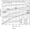
- FIG. 8 is a schematic diagram of a probability that all second pilots conflict when at least two second pilots are sent.
- a horizontal coordinate is a quantity of access users, and a vertical coordinate is a conflict probability.
- a curve 801 (with a mark "+"), a curve 802 (with a mark “ ⁇ ”), a curve 803 (with a mark " ⁇ "), and a curve 804 (with a mark “ ⁇ ”) are respectively scenarios in which one second pilot, two second pilots, three second pilots, and four second pilots are sent.
- a second pilot space includes 30 orthogonal sequences.
- Other curves are scenarios in which only one second pilot is sent and quantities of sequences in second pilot spaces are different (the quantities of sequences are shown in FIG. 8 from top to bottom). Points intersected of the curve 801 to the curve 804 and lines with no mark reflect a quantity of equivalent sequences in the second pilot space in this case.
- the terminal device and the network device in the embodiments of this application are described in detail below.
- FIG. 9 is a schematic block diagram of a terminal device 100 according to an embodiment of this application. As shown in FIG. 9 , the terminal device 100 includes:
- pilots When the terminal device provided in this application sends pilots, two pilots are distinguished. A first pilot is used for terminal device detection, a second pilot group corresponding to the first pilot is used for frequency offset estimation, and each second pilot in the second pilot group is repeated on at least two symbols of a time unit. This can support accurate frequency offset estimation, thereby improving system performance.
- the terminal device 100 may further include a memory 130.
- the memory 130 may be configured to store code executed by the processor 110.
- Components of the terminal device 100 are coupled together by using a bus system 140.
- the bus system 140 includes a power bus, a control bus, and a status signal bus.
- the processor may be an integrated circuit chip and has a signal processing capability.
- steps in the foregoing method embodiments can be implemented by using a hardware integrated logical circuit in the processor, or by using instructions in a form of software.
- the processor may be a general purpose processor, a digital signal processor (digital signal processor, DSP), an application-specific integrated circuit (application specific integrated circuit, ASIC), a field programmable gate array (field programmable gate array, FPGA) or another programmable logical device, a discrete gate or transistor logic device, or a discrete hardware component.
- the general purpose processor may be a microprocessor, or the processor may be any conventional processor or the like. Steps of the methods disclosed with reference to the embodiments of this application may be directly executed and accomplished by means of a hardware decoding processor, or may be executed and accomplished by using a combination of hardware and software modules in the decoding processor.
- a software module may be located in a mature storage medium in the art, such as a random access memory, a flash memory, a read-only memory, a programmable read-only memory, an electrically erasable programmable memory, a register, or the like. The storage medium is located in the memory, and a processor reads information in the memory and completes the steps in the foregoing methods in combination with hardware of the processor.
- the memory in the embodiments of this application may be a volatile memory or a nonvolatile memory, or may include a volatile memory and a nonvolatile memory.
- the nonvolatile memory may be a read-only memory (read-only memory, ROM), a programmable read-only memory (programmable ROM, PROM), an erasable programmable read-only memory (erasable PROM, EPROM), an electrically erasable programmable read-only memory (electrically EPROM, EEPROM), or a flash memory.
- the volatile memory may be a random access memory (random access memory, RAM), used as an external cache.
- RAMs may be used, for example, a static random access memory (static RAM, SRAM), a dynamic random access memory (dynamic RAM, DRAM), a synchronous dynamic random access memory (synchronous DRAM, SDRAM), a double data rate synchronous dynamic random access memory (double data rate SDRAM, DDR SDRAM), an enhanced synchronous dynamic random access memory (enhanced SDRAM, ESDRAM), a synchronous link dynamic random access memory (synchlink DRAM, SLDRAM), and a direct rambus dynamic random access memory (direct rambus RAM, DR RAM).
- static random access memory static random access memory
- DRAM dynamic random access memory
- DRAM dynamic random access memory
- SDRAM synchronous dynamic random access memory
- double data rate SDRAM double data rate SDRAM
- DDR SDRAM double data rate SDRAM
- ESDRAM enhanced synchronous dynamic random access memory
- SLDRAM synchronous link dynamic random access memory
- direct rambus RAM direct rambus RAM
- the target first pilot is a pilot in a first pilot set
- the first pilot set includes a universal set of pilots used to perform terminal device detection and used by a terminal device served by the network device
- each second pilot in the target second pilot group is a pilot in a second pilot set
- the second pilot set includes a universal set of pilots used to perform frequency offset estimation and used by the terminal device served by the network device
- the first pilot set includes two first pilots having a degree of coherence greater than zero, and a degree of coherence between any two second pilots in the second pilot set is zero.
- the target first pilot is a Reed-Muller sequence or a Zadoff-Chu sequence
- each second pilot in the target second pilot group is a Reed-Muller sequence or a Zadoff-Chu sequence.
- the transceiver 120 may be further configured to: before the processor determines the target first pilot and the target second pilot group corresponding to the target first pilot, receive Radio Resource Control RRC signaling sent by the network device, where the RRC signaling includes information used to indicate a correspondence between a first pilot and a second pilot group.
- the processor 110 is specifically configured to: determine the target first pilot; and determine, based on the correspondence, the target second pilot group corresponding to the target first pilot.
- any two second pilots in the target second pilot group are orthogonal in code domain, or occupy orthogonal time frequency resources.
- second pilots of different terminal devices that occupy a same time frequency resource are orthogonal in code domain, or time frequency resources occupied by second pilots of different terminal devices are orthogonal.
- a terminal device 200 may include a processing module 210 and a transceiver module 220.
- the terminal device 100 shown in FIG. 9 or the terminal device 200 shown in FIG. 10 can implement various processes implemented in the embodiments of FIG. 3 to FIG. 8 . To avoid repetition, details are not described herein again.
- FIG. 11 is a schematic block diagram of a network device 300 according to an embodiment of this application. As shown in FIG. 11 , the network device 300 may include:
- the processor 320 is further configured to perform frequency offset estimation based on a second pilot that is in the target second pilot group received by the transceiver 310 and that is repeatedly sent on the at least two symbols of the time unit.
- Pilots received by the network device provided in this application include two pilots.
- a first pilot is used for terminal device detection, a second pilot group corresponding to the first pilot is used for frequency offset estimation, and each second pilot in the second pilot group is repeated on at least two symbols of a time unit. This can support accurate frequency offset estimation, thereby improving system performance.
- the network device 300 may further include a memory 330.
- the memory 330 may be configured to store code executed by the processor 320.
- Components of the network device 300 are coupled together by using a bus system 340.
- the bus system 340 includes a power bus, a control bus, and a status signal bus.
- the target first pilot is a pilot in a first pilot set
- the first pilot set includes a universal set of pilots used to perform terminal device detection and used by a terminal device served by the network device
- each second pilot in the target second pilot group is a pilot in a second pilot set
- the second pilot set includes a universal set of pilots used to perform frequency offset estimation and used by the terminal device served by the network device
- the first pilot set includes two first pilots having a degree of coherence greater than zero, and a degree of coherence between any two second pilots in the second pilot set is zero.
- the target first pilot is a Reed-Muller sequence or a Zadoff-Chu sequence
- each second pilot in the target second pilot group is a Reed-Muller sequence or a Zadoff-Chu sequence.
- the transceiver 310 is specifically configured to: receive at least one first pilot and at least one second pilot group in the time unit, where each of the at least one second pilot group includes at least two second pilots, the at least one first pilot includes the target first pilot, and the at least one second pilot group includes the target second pilot group.
- the processor 320 is specifically configured to: perform terminal device detection based on the target first pilot, to determine that a terminal device corresponding to the target first pilot is the first terminal device.
- the processor 320 is further configured to: determine, by the network device based on a correspondence between a first pilot and a second pilot group, the target second pilot group corresponding to the target first pilot in the at least one second pilot group.
- the transceiver 310 is further configured to: send Radio Resource Control RRC signaling to the first terminal device, where the RRC signaling includes information used to indicate the correspondence between a first pilot and a second pilot group.
- RRC signaling includes information used to indicate the correspondence between a first pilot and a second pilot group.
- any two second pilots in the target second pilot group are orthogonal in code domain, or occupy orthogonal time frequency resources.
- second pilots of different terminal devices that occupy a same time frequency resource are orthogonal in code domain, or time frequency resources occupied by second pilots of different terminal devices are orthogonal.
- the processor 320 is specifically configured to: perform frequency offset estimation based on a phase difference of at least one second pilot, which does not conflict with another terminal device in the target second pilot group, repeatedly sent on the at least two symbols of the time unit.
- a network device 400 may include a transceiver module 410 and a processing module 420.
- the network device 300 shown in FIG. 11 or the network device 400 shown in FIG. 12 can implement various processes implemented in the embodiments of FIG. 3 to FIG. 8 . To avoid repetition, details are not described herein again.
- Methods or steps described in the embodiments disclosed in this specification may be implemented by hardware, a software program executed by a processor, or a combination thereof.
- the software program may reside in a random access memory (RAM), a memory, a read-only memory (ROM), an electrically programmable ROM, an electrically erasable programmable ROM, a register, a hard disk, a removable disk, a CD-ROM, or any other form of storage medium known in the art.
Landscapes
- Engineering & Computer Science (AREA)
- Signal Processing (AREA)
- Computer Networks & Wireless Communication (AREA)
- Power Engineering (AREA)
- Databases & Information Systems (AREA)
- Health & Medical Sciences (AREA)
- Computing Systems (AREA)
- General Health & Medical Sciences (AREA)
- Medical Informatics (AREA)
- Mobile Radio Communication Systems (AREA)
Claims (12)
- Pilotsignalübertragungsverfahren, umfassend:Empfangen von durch eine Netzwerkvorrichtung gesendete Funkressourcensteuerungs-, RRC-Signalisierung durch eine Endgerätevorrichtung,wobei die RRC-Signalisierung Informationen umfasst, die dazu verwendet werden, eine Entsprechung zwischen einem ersten Pilotsignal und einer zweiten Pilotsignalgruppe anzuzeigen;Bestimmen eines ersten Zielpilotsignals durch die erste Endgerätevorrichtung;Bestimmen einer zweiten Zielpilotsignalgruppe entsprechend dem ersten Zielpilotsignal durch die erste Endgerätevorrichtung basierend auf der Entsprechung, wobei das erste Zielpilotsignal durch die Netzwerkvorrichtung dazu verwendet wird,eine Endgerätevorrichtungserkennung durchzuführen, und die zweite Zielpilotsignalgruppe mindestens zwei zweite Pilotsignale umfasst; undSenden des ersten Zielpilotsignals und der zweiten Zielpilotsignalgruppe in einer Zeiteinheit durch die erste Endgerätevorrichtung an die Netzwerkvorrichtung, wobei jedes zweite Pilotsignal in der zweiten Zielpilotsignalgruppe wiederholt auf mindestens zwei Symbolen der Zeiteinheit gesendet wird, und die zweite Zielpilotsignalgruppe durch die Netzwerkvorrichtung dazu verwendet wird, eine Frequenzversatzschätzung durchzuführen.
- Verfahren gemäß Anspruch 1, wobei das erste Zielpilotsignal ein Pilotsignal in einem ersten Pilotsignalsatz ist und der erste Pilotsignalsatz einen universellen Satz von Pilotsignalen umfasst, die zum Durchführen einer Endgerätevorrichtungserkennung verwendet werden und durch eine durch die Netzwerkvorrichtung bediente Endgerätevorrichtung verwendet werden;
jedes zweite Pilotsignal in der zweiten Zielpilotsignalgruppe ein Pilotsignal in einem zweiten Pilotsignalsatz ist und der zweite Pilotsignalsatz einen universellen Satz von Pilotsignalen umfasst, die dazu verwendet werden, eine Frequenzversatzschätzung durchzuführen, und die durch die durch die Netzwerkvorrichtung bediente Endgerätevorrichtung verwendet werden; und
der erste Pilotsignalsatz zwei erste Pilotsignale mit einem Kohärenzgrad größer als null umfasst, und
ein Kohärenzgrad zwischen zwei beliebigen zweiten Pilotsignalen im zweiten Pilotsignalsatz null ist. - Verfahren gemäß Anspruch 1 oder 2, wobei das erste Zielpilotsignal eine Reed-Muller-Sequenz oder eine Zadoff-Chu-Sequenz ist; und
jedes zweite Pilotsignal in der zweiten Zielpilotsignalgruppe eine Reed-Muller-Sequenz oder eine Zadoff-Chu-Sequenz ist. - Pilotsignalempfangsverfahren, umfassend:Senden von Funkressourcensteuerungs-, RRC-Signalisierung durch eine Netzwerkvorrichtung an eine erste Endgerätevorrichtung, wobei die RRC-Signalisierung Informationen umfasst, die dazu verwendet werden, eine Entsprechung zwischen einem ersten Pilotsignal und einer zweiten Pilotsignalgruppe anzuzeigen;Empfangen eines durch die erste Endgerätevorrichtung in einer Zeiteinheit gesendeten ersten Zielpilotsignals und einer zweiten Zielpilotsignalgruppe, die dem ersten Zielpilotsignal entspricht und die durch die erste Endgerätevorrichtung wiederholt auf mindestens zwei Symbolen der Zeiteinheit gesendet wird, durch die Netzwerkvorrichtung, wobei die zweite Zielpilotsignalgruppe mindestens zwei zweite Pilotsignale umfasst;Durchführen einer Endgerätevorrichtungserkennung basierend auf dem ersten Zielpilotsignal durch die Netzwerkvorrichtung; undDurchführen einer Frequenzversatzschätzung durch die Netzwerkvorrichtung basierend auf einem zweiten Pilotsignal in der zweiten Zielpilotsignalgruppe, das wiederholt auf den mindestens zwei Symbolen der Zeiteinheit gesendet wird.
- Verfahren gemäß Anspruch 4, wobei das erste Zielpilotsignal ein Pilotsignal in einem ersten Pilotsignalsatz ist und der erste Pilotsignalsatz einen universellen Satz von Pilotsignalen umfasst, die zum Durchführen einer Endgerätevorrichtungserkennung verwendet werden und durch eine durch die Netzwerkvorrichtung bediente Endgerätevorrichtung verwendet werden;
jedes zweite Pilotsignal in der zweiten Zielpilotsignalgruppe ein Pilotsignal in einem zweiten Pilotsignalsatz ist und der zweite Pilotsignalsatz einen universellen Satz von Pilotsignalen umfasst, die dazu verwendet werden, eine Frequenzversatzschätzung durchzuführen, und die durch die durch die Netzwerkvorrichtung bediente Endgerätevorrichtung verwendet werden; und
der erste Pilotsignalsatz zwei erste Pilotsignale mit einen Kohärenzgrad größer als null umfasst und ein Kohärenzgrad zwischen zwei beliebigen zweiten Pilotsignalen im zweiten Pilotsignalsatz null ist. - Verfahren gemäß Anspruch 4 oder 5, wobei das erste Zielpilotsignal eine Reed-Muller-Sequenz oder eine Zadoff-Chu-Sequenz ist; und
jedes zweite Pilotsignal in der zweiten Zielpilotsignalgruppe eine Reed-Muller-Sequenz oder eine Zadoff-Chu-Sequenz ist. - Endgerätevorrichtung, umfassend:einen Sender-Empfänger, der dazu ausgelegt ist, durch eine Netzwerkvorrichtung gesendete Funkressourcensteuerungs-, RRC-Signalisierung zu empfangen, wobei die RRC-Signalisierung Informationen umfasst, die dazu verwendet werden, eine Entsprechung zwischen einer ersten Pilotsignalgruppe und einer zweiten Pilotsignalgruppe anzuzeigen;einen Prozessor, der dazu ausgelegt ist, ein erstes Zielpilotsignal zu bestimmen;wobei der Prozessor ferner dazu ausgelegt ist, basierend auf der Entsprechung eine zweite Zielpilotsignalgruppe entsprechend dem ersten Zielpilotsignal zu bestimmen,wobei das erste Zielpilotsignal durch die Netzwerkvorrichtung dazu verwendet wird,eine Endgerätevorrichtungserkennung durchzuführen, und die zweite Zielpilotsignalgruppe mindestens zwei zweite Pilotsignale umfasst;der Sender-Empfänger ferner dazu ausgelegt ist, das erste Zielpilotsignal und die zweite Zielpilotsignalgruppe, die durch den Prozessor bestimmt werden, in einer Zeiteinheit an die Netzwerkvorrichtung zu senden, wobei jedes zweite Pilotsignal in der zweiten Zielpilotsignalgruppe wiederholt auf mindestens zwei Symbolen der Zeiteinheit gesendet wird und die zweite Zielpilotsignalgruppe durch die Netzwerkvorrichtung dazu verwendet wird, eine Frequenzversatzschätzung durchzuführen.
- Endgerätevorrichtung gemäß Anspruch 7, wobei das erste Zielpilotsignal ein Pilotsignal in einem ersten Pilotsignalsatz ist und der erste Pilotsignalsatz einen universellen Satz von Pilotsignalen umfasst, die zum Durchführen einer Endgerätevorrichtungserkennung verwendet werden und durch eine durch die Netzwerkvorrichtung bediente Endgerätevorrichtung verwendet werden;
jedes zweite Pilotsignal in der zweiten Zielpilotsignalgruppe ein Pilotsignal in einem zweiten Pilotsignalsatz ist und der zweite Pilotsignalsatz einen universellen Satz von Pilotsignalen umfasst, die dazu verwendet werden, eine Frequenzversatzschätzung durchzuführen, und die durch die durch die Netzwerkvorrichtung bediente Endgerätevorrichtung verwendet werden; und
der erste Pilotsignalsatz zwei erste Pilotsignale mit einen Kohärenzgrad größer als null umfasst und ein Kohärenzgrad zwischen zwei beliebigen zweiten Pilotsignalen im zweiten Pilotsignalsatz null ist. - Endgerätevorrichtung gemäß Anspruch 7 oder 8, wobei das erste Zielpilotsignal eine Reed-Muller-Sequenz oder eine Zadoff-Chu-Sequenz ist; und
jedes zweite Pilotsignal in der zweiten Zielpilotsignalgruppe eine Reed-Muller-Sequenz oder eine Zadoff-Chu-Sequenz ist. - Netzwerkvorrichtung, umfassend:einen Sender-Empfänger, der dazu ausgelegt ist, Funkressourcensteuerungs-, RRC-Signalisierung an eine erste Endgerätevorrichtung zu senden, wobei die RRC-Signalisierung Informationen umfasst, die dazu verwendet werden, eine Entsprechung zwischen einem ersten Pilotsignal und einer zweiten Pilotsignalgruppe anzuzeigen, wobeider Sender-Empfänger ferner dazu ausgelegt ist, ein durch die erste Endgerätevorrichtung in einer Zeiteinheit gesendetes erstes Zielpilotsignal und eine zweite Zielpilotsignalgruppe zu empfangen, die dem ersten Zielpilotsignal entspricht und die durch die erste Endgerätevorrichtung wiederholt auf mindestens zwei Symbolen der Zeiteinheit gesendet wird, wobei die zweite Zielpilotsignalgruppe mindestens zwei zweite Pilotsignale umfasst; undeinen Prozessor, der dazu ausgelegt ist, eine Endgerätevorrichtungserkennung basierend auf dem durch den Sender-Empfänger empfangenen ersten Zielpilotsignal durchzuführen, wobeider Prozessor ferner dazu ausgelegt ist, eine Frequenzversatzschätzung basierend auf einem zweiten Pilotsignal durchzuführen, der sich in der durch den Sender-Empfänger empfangenen zweiten Zielpilotsignalgruppe befindet und der wiederholt auf den mindestens zwei Symbolen der Zeiteinheit gesendet wird.
- Netzwerkvorrichtung gemäß Anspruch 10, wobei das erste Zielpilotsignal ein Pilotsignal in einem ersten Pilotsignalsatz ist und der erste Pilotsignalsatz einen universellen Satz von Pilotsignalen umfasst, die zum Durchführen einer Endgerätevorrichtungserkennung verwendet werden und durch eine durch die Netzwerkvorrichtung bediente Endgerätevorrichtung verwendet werden;
jedes zweite Pilotsignal in der zweiten Zielpilotsignalgruppe ein Pilotsignal in einem zweiten Pilotsignalsatz ist und der zweite Pilotsignalsatz einen universellen Satz von Pilotsignalen umfasst, die dazu verwendet werden, eine Frequenzversatzschätzung durchzuführen, und die durch die durch die Netzwerkvorrichtung bediente Endgerätevorrichtung verwendet werden; und
der erste Pilotsignalsatz zwei erste Pilotsignale mit einen Kohärenzgrad größer als null umfasst und ein Kohärenzgrad zwischen zwei beliebigen zweiten Pilotsignalen im zweiten Pilotsignalsatz null ist. - Netzwerkvorrichtung gemäß Anspruch 10 oder 11, wobei das erste Zielpilotsignal eine Reed-Muller-Sequenz oder eine Zadoff-Chu-Sequenz ist; und
jedes zweite Pilotsignal in der zweiten Zielpilotsignalgruppe eine Reed-Muller-Sequenz oder eine Zadoff-Chu-Sequenz ist.
Applications Claiming Priority (2)
| Application Number | Priority Date | Filing Date | Title |
|---|---|---|---|
| CN201610802887.5A CN107800525B (zh) | 2016-09-05 | 2016-09-05 | 传输导频的方法、终端设备和网络设备 |
| PCT/CN2017/098329 WO2018040974A1 (zh) | 2016-09-05 | 2017-08-21 | 传输导频的方法、终端设备和网络设备 |
Publications (3)
| Publication Number | Publication Date |
|---|---|
| EP3496321A1 EP3496321A1 (de) | 2019-06-12 |
| EP3496321A4 EP3496321A4 (de) | 2019-08-21 |
| EP3496321B1 true EP3496321B1 (de) | 2021-08-04 |
Family
ID=61300087
Family Applications (1)
| Application Number | Title | Priority Date | Filing Date |
|---|---|---|---|
| EP17845276.9A Active EP3496321B1 (de) | 2016-09-05 | 2017-08-21 | Pilotsignalübertragungs-/empfangs-verfahren, endgeräteausrüstung und netzwerkausrüstung |
Country Status (4)
| Country | Link |
|---|---|
| US (1) | US10819487B2 (de) |
| EP (1) | EP3496321B1 (de) |
| CN (1) | CN107800525B (de) |
| WO (1) | WO2018040974A1 (de) |
Families Citing this family (6)
| Publication number | Priority date | Publication date | Assignee | Title |
|---|---|---|---|---|
| EP3456128B1 (de) * | 2016-05-12 | 2022-01-26 | Nokia Technologies Oy | Verfahren und vorrichtung zur unterbrechung einer uplink-übertragung während eines übertragungszeitintervalls |
| EP3952236B1 (de) | 2019-04-18 | 2025-01-01 | Beijing Xiaomi Mobile Software Co., Ltd. | Frequenzversatzbestimmungsverfahren und -vorrichtung und ressourcenblockübertragungsverfahren und -vorrichtung |
| KR20220018358A (ko) * | 2020-08-06 | 2022-02-15 | 삼성전자주식회사 | 주파수 오프셋을 사용하는 비직교 다중 접속 시스템에서 채널 추정 방법 및 장치 |
| CN114095137A (zh) * | 2020-08-24 | 2022-02-25 | 华为技术有限公司 | 一种无线通信的方法及装置 |
| CN112039648A (zh) * | 2020-08-28 | 2020-12-04 | 中兴通讯股份有限公司 | 数据传输方法、装置、传输设备及存储介质 |
| CN119921916A (zh) * | 2023-10-31 | 2025-05-02 | 华为技术有限公司 | 导频信号的传输方法、装置及系统 |
Family Cites Families (16)
| Publication number | Priority date | Publication date | Assignee | Title |
|---|---|---|---|---|
| WO2005074305A1 (en) * | 2004-01-29 | 2005-08-11 | Neocific, Inc. | Methods and apparatus for multi-carrier, multi-cell wireless communication networks |
| US8594151B2 (en) * | 2005-10-31 | 2013-11-26 | Nokia Corporation | Pilot sequence detection |
| KR100913089B1 (ko) * | 2006-02-07 | 2009-08-21 | 엘지전자 주식회사 | 다중 반송파 시스템에 적용되는 파일럿 신호 전송 방법 |
| CN101132384B (zh) * | 2006-08-23 | 2011-01-12 | 大唐移动通信设备有限公司 | 一种ofdm系统中导频复用方法及装置 |
| EP2099233B1 (de) * | 2006-12-22 | 2013-09-04 | Fujitsu Limited | Zadoff-Chu basierte Pilot Signale für die Aufwärtsverbindung |
| CN101137224B (zh) | 2007-03-12 | 2010-09-29 | 中兴通讯股份有限公司 | 用于多载波系统的导频更新装置及软切换方法 |
| CN101277288A (zh) * | 2007-03-30 | 2008-10-01 | 中兴通讯股份有限公司 | 正交频分复用系统的频率同步方法 |
| GB2482122B (en) | 2010-07-19 | 2014-02-19 | Intellectual Ventures Holding 81 Llc | Communication unit and pilot method for time varying channels |
| KR101791987B1 (ko) * | 2010-12-07 | 2017-11-20 | 한국전자통신연구원 | 무선 통신 시스템에서 프리앰블 전송 방법 및 장치 |
| US8767848B2 (en) * | 2010-12-23 | 2014-07-01 | Texas Instruments Incorporated | Channel estimation based on long training symbol with doubled cyclic prefix |
| KR101622798B1 (ko) * | 2011-02-11 | 2016-05-20 | 삼성전자주식회사 | 무선 통신 시스템에서 채널 추정 방법 및 장치 |
| CN103686689B (zh) * | 2012-09-12 | 2017-11-07 | 华为技术有限公司 | 一种设备到设备通信中通信终端的发现方法及通信终端 |
| US9071327B2 (en) * | 2012-11-27 | 2015-06-30 | Gilat Satellite Networks Ltd. | Efficient frequency estimation |
| FR3026907B1 (fr) * | 2014-10-03 | 2017-11-24 | B<>Com | Procede d'emission d'un signal multi-porteuses, procede de reception, dispositifs, et programmes d'ordinateurs associes |
| WO2016134763A1 (en) * | 2015-02-25 | 2016-09-01 | Huawei Technologies Co., Ltd. | Pilot pattern for wifi ofdma |
| US9755881B1 (en) * | 2015-07-28 | 2017-09-05 | Marvell Israel (M.I.S.L) Ltd. | Receiver with data-aided automatic frequency control |
-
2016
- 2016-09-05 CN CN201610802887.5A patent/CN107800525B/zh active Active
-
2017
- 2017-08-21 WO PCT/CN2017/098329 patent/WO2018040974A1/zh not_active Ceased
- 2017-08-21 EP EP17845276.9A patent/EP3496321B1/de active Active
-
2019
- 2019-03-04 US US16/291,919 patent/US10819487B2/en active Active
Also Published As
| Publication number | Publication date |
|---|---|
| EP3496321A1 (de) | 2019-06-12 |
| US20190260526A1 (en) | 2019-08-22 |
| WO2018040974A1 (zh) | 2018-03-08 |
| CN107800525B (zh) | 2020-10-09 |
| CN107800525A (zh) | 2018-03-13 |
| EP3496321A4 (de) | 2019-08-21 |
| US10819487B2 (en) | 2020-10-27 |
Similar Documents
| Publication | Publication Date | Title |
|---|---|---|
| US11757603B2 (en) | Method and device for transmitting uplink demodulation reference signal | |
| EP3496321B1 (de) | Pilotsignalübertragungs-/empfangs-verfahren, endgeräteausrüstung und netzwerkausrüstung | |
| US10812305B2 (en) | Signal transmission method, transmit end, and receive end | |
| EP3576334B1 (de) | Verfahren für dmrs-übertragung und kommunikationsvorrichtung | |
| JP7064602B2 (ja) | 無線通信方法及び装置 | |
| EP3457735B1 (de) | Verfahren zur übertragung einer benutzersequenz, netzwerkvorrichtung und endgerätevorrichtung | |
| CN110800351B (zh) | 无线通信方法、终端和网络设备 | |
| US12132570B2 (en) | Sequence-based signal transmission method and communication apparatus | |
| CN110912660B (zh) | 生成参考信号的方法和装置 | |
| US20160112221A1 (en) | Method for ue and user equipment | |
| JP2021513790A (ja) | 通信方法、通信デバイス、及びネットワークデバイス | |
| EP4068714B1 (de) | Referenzsignalsende- und signaldetektionsverfahren und -vorrichtung | |
| CN111757367B (zh) | 一种干扰检测方法、信号发送方法及装置 | |
| CN113067608A (zh) | 传输上行信号的方法、终端设备和网络侧设备 | |
| CN114175793B (zh) | 无线通信方法和终端设备 | |
| US10763948B2 (en) | Signal sending method and apparatus, and signal receiving method and apparatus | |
| EP3641206B1 (de) | Verfahren und vorrichtung zur übertragung von informationen | |
| US20250175373A1 (en) | Reference signal transmission method and communication apparatus | |
| EP4319009A1 (de) | Drahtloskommunikationsverfahren, endgerätevorrichtung und netzwerkvorrichtung | |
| US12335185B2 (en) | Method and apparatus for transmitting and receiving signal using orthogonal sequence in communication system | |
| US11382077B2 (en) | PUCCH transmission method, terminal and network-side device | |
| EP3614611B1 (de) | Kommunikationsverfahren und -vorrichtung | |
| CN121002801A (zh) | 用于无线通信的探测参考信号增强方法和系统 | |
| CN118540036A (zh) | 探测参考信号传输方法及装置、计算机可读存储介质 | |
| HK40003068B (en) | Method for transmitting uplink signal, terminal device and network side device |
Legal Events
| Date | Code | Title | Description |
|---|---|---|---|
| STAA | Information on the status of an ep patent application or granted ep patent |
Free format text: STATUS: THE INTERNATIONAL PUBLICATION HAS BEEN MADE |
|
| PUAI | Public reference made under article 153(3) epc to a published international application that has entered the european phase |
Free format text: ORIGINAL CODE: 0009012 |
|
| STAA | Information on the status of an ep patent application or granted ep patent |
Free format text: STATUS: REQUEST FOR EXAMINATION WAS MADE |
|
| 17P | Request for examination filed |
Effective date: 20190308 |
|
| AK | Designated contracting states |
Kind code of ref document: A1 Designated state(s): AL AT BE BG CH CY CZ DE DK EE ES FI FR GB GR HR HU IE IS IT LI LT LU LV MC MK MT NL NO PL PT RO RS SE SI SK SM TR |
|
| AX | Request for extension of the european patent |
Extension state: BA ME |
|
| A4 | Supplementary search report drawn up and despatched |
Effective date: 20190719 |
|
| RIC1 | Information provided on ipc code assigned before grant |
Ipc: H04L 27/00 20060101ALI20190715BHEP Ipc: H04W 56/00 20090101ALI20190715BHEP Ipc: H04L 1/00 20060101ALI20190715BHEP Ipc: H04L 27/26 20060101ALI20190715BHEP Ipc: H04L 5/00 20060101AFI20190715BHEP |
|
| DAV | Request for validation of the european patent (deleted) | ||
| DAX | Request for extension of the european patent (deleted) | ||
| GRAP | Despatch of communication of intention to grant a patent |
Free format text: ORIGINAL CODE: EPIDOSNIGR1 |
|
| STAA | Information on the status of an ep patent application or granted ep patent |
Free format text: STATUS: GRANT OF PATENT IS INTENDED |
|
| RIC1 | Information provided on ipc code assigned before grant |
Ipc: H04W 56/00 20090101ALI20210204BHEP Ipc: H04L 1/00 20060101ALI20210204BHEP Ipc: H04J 13/00 20110101ALI20210204BHEP Ipc: H04L 25/02 20060101ALI20210204BHEP Ipc: H04L 27/26 20060101ALI20210204BHEP Ipc: H04L 5/00 20060101AFI20210204BHEP Ipc: H04L 27/00 20060101ALI20210204BHEP |
|
| INTG | Intention to grant announced |
Effective date: 20210303 |
|
| GRAS | Grant fee paid |
Free format text: ORIGINAL CODE: EPIDOSNIGR3 |
|
| GRAA | (expected) grant |
Free format text: ORIGINAL CODE: 0009210 |
|
| STAA | Information on the status of an ep patent application or granted ep patent |
Free format text: STATUS: THE PATENT HAS BEEN GRANTED |
|
| AK | Designated contracting states |
Kind code of ref document: B1 Designated state(s): AL AT BE BG CH CY CZ DE DK EE ES FI FR GB GR HR HU IE IS IT LI LT LU LV MC MK MT NL NO PL PT RO RS SE SI SK SM TR |
|
| REG | Reference to a national code |
Ref country code: GB Ref legal event code: FG4D |
|
| REG | Reference to a national code |
Ref country code: AT Ref legal event code: REF Ref document number: 1418105 Country of ref document: AT Kind code of ref document: T Effective date: 20210815 |
|
| REG | Reference to a national code |
Ref country code: CH Ref legal event code: EP |
|
| REG | Reference to a national code |
Ref country code: DE Ref legal event code: R096 Ref document number: 602017043568 Country of ref document: DE |
|
| REG | Reference to a national code |
Ref country code: IE Ref legal event code: FG4D |
|
| REG | Reference to a national code |
Ref country code: LT Ref legal event code: MG9D |
|
| REG | Reference to a national code |
Ref country code: NL Ref legal event code: MP Effective date: 20210804 |
|
| REG | Reference to a national code |
Ref country code: AT Ref legal event code: MK05 Ref document number: 1418105 Country of ref document: AT Kind code of ref document: T Effective date: 20210804 |
|
| PG25 | Lapsed in a contracting state [announced via postgrant information from national office to epo] |
Ref country code: HR Free format text: LAPSE BECAUSE OF FAILURE TO SUBMIT A TRANSLATION OF THE DESCRIPTION OR TO PAY THE FEE WITHIN THE PRESCRIBED TIME-LIMIT Effective date: 20210804 Ref country code: ES Free format text: LAPSE BECAUSE OF FAILURE TO SUBMIT A TRANSLATION OF THE DESCRIPTION OR TO PAY THE FEE WITHIN THE PRESCRIBED TIME-LIMIT Effective date: 20210804 Ref country code: FI Free format text: LAPSE BECAUSE OF FAILURE TO SUBMIT A TRANSLATION OF THE DESCRIPTION OR TO PAY THE FEE WITHIN THE PRESCRIBED TIME-LIMIT Effective date: 20210804 Ref country code: SE Free format text: LAPSE BECAUSE OF FAILURE TO SUBMIT A TRANSLATION OF THE DESCRIPTION OR TO PAY THE FEE WITHIN THE PRESCRIBED TIME-LIMIT Effective date: 20210804 Ref country code: RS Free format text: LAPSE BECAUSE OF FAILURE TO SUBMIT A TRANSLATION OF THE DESCRIPTION OR TO PAY THE FEE WITHIN THE PRESCRIBED TIME-LIMIT Effective date: 20210804 Ref country code: LT Free format text: LAPSE BECAUSE OF FAILURE TO SUBMIT A TRANSLATION OF THE DESCRIPTION OR TO PAY THE FEE WITHIN THE PRESCRIBED TIME-LIMIT Effective date: 20210804 Ref country code: AT Free format text: LAPSE BECAUSE OF FAILURE TO SUBMIT A TRANSLATION OF THE DESCRIPTION OR TO PAY THE FEE WITHIN THE PRESCRIBED TIME-LIMIT Effective date: 20210804 Ref country code: BG Free format text: LAPSE BECAUSE OF FAILURE TO SUBMIT A TRANSLATION OF THE DESCRIPTION OR TO PAY THE FEE WITHIN THE PRESCRIBED TIME-LIMIT Effective date: 20211104 Ref country code: NO Free format text: LAPSE BECAUSE OF FAILURE TO SUBMIT A TRANSLATION OF THE DESCRIPTION OR TO PAY THE FEE WITHIN THE PRESCRIBED TIME-LIMIT Effective date: 20211104 Ref country code: PT Free format text: LAPSE BECAUSE OF FAILURE TO SUBMIT A TRANSLATION OF THE DESCRIPTION OR TO PAY THE FEE WITHIN THE PRESCRIBED TIME-LIMIT Effective date: 20211206 |
|
| PG25 | Lapsed in a contracting state [announced via postgrant information from national office to epo] |
Ref country code: PL Free format text: LAPSE BECAUSE OF FAILURE TO SUBMIT A TRANSLATION OF THE DESCRIPTION OR TO PAY THE FEE WITHIN THE PRESCRIBED TIME-LIMIT Effective date: 20210804 Ref country code: LV Free format text: LAPSE BECAUSE OF FAILURE TO SUBMIT A TRANSLATION OF THE DESCRIPTION OR TO PAY THE FEE WITHIN THE PRESCRIBED TIME-LIMIT Effective date: 20210804 Ref country code: GR Free format text: LAPSE BECAUSE OF FAILURE TO SUBMIT A TRANSLATION OF THE DESCRIPTION OR TO PAY THE FEE WITHIN THE PRESCRIBED TIME-LIMIT Effective date: 20211105 |
|
| REG | Reference to a national code |
Ref country code: CH Ref legal event code: PL |
|
| PG25 | Lapsed in a contracting state [announced via postgrant information from national office to epo] |
Ref country code: NL Free format text: LAPSE BECAUSE OF FAILURE TO SUBMIT A TRANSLATION OF THE DESCRIPTION OR TO PAY THE FEE WITHIN THE PRESCRIBED TIME-LIMIT Effective date: 20210804 |
|
| REG | Reference to a national code |
Ref country code: BE Ref legal event code: MM Effective date: 20210831 |
|
| PG25 | Lapsed in a contracting state [announced via postgrant information from national office to epo] |
Ref country code: LI Free format text: LAPSE BECAUSE OF NON-PAYMENT OF DUE FEES Effective date: 20210831 Ref country code: DK Free format text: LAPSE BECAUSE OF FAILURE TO SUBMIT A TRANSLATION OF THE DESCRIPTION OR TO PAY THE FEE WITHIN THE PRESCRIBED TIME-LIMIT Effective date: 20210804 Ref country code: CH Free format text: LAPSE BECAUSE OF NON-PAYMENT OF DUE FEES Effective date: 20210831 |
|
| REG | Reference to a national code |
Ref country code: DE Ref legal event code: R097 Ref document number: 602017043568 Country of ref document: DE |
|
| PG25 | Lapsed in a contracting state [announced via postgrant information from national office to epo] |
Ref country code: SM Free format text: LAPSE BECAUSE OF FAILURE TO SUBMIT A TRANSLATION OF THE DESCRIPTION OR TO PAY THE FEE WITHIN THE PRESCRIBED TIME-LIMIT Effective date: 20210804 Ref country code: SK Free format text: LAPSE BECAUSE OF FAILURE TO SUBMIT A TRANSLATION OF THE DESCRIPTION OR TO PAY THE FEE WITHIN THE PRESCRIBED TIME-LIMIT Effective date: 20210804 Ref country code: RO Free format text: LAPSE BECAUSE OF FAILURE TO SUBMIT A TRANSLATION OF THE DESCRIPTION OR TO PAY THE FEE WITHIN THE PRESCRIBED TIME-LIMIT Effective date: 20210804 Ref country code: MC Free format text: LAPSE BECAUSE OF FAILURE TO SUBMIT A TRANSLATION OF THE DESCRIPTION OR TO PAY THE FEE WITHIN THE PRESCRIBED TIME-LIMIT Effective date: 20210804 Ref country code: EE Free format text: LAPSE BECAUSE OF FAILURE TO SUBMIT A TRANSLATION OF THE DESCRIPTION OR TO PAY THE FEE WITHIN THE PRESCRIBED TIME-LIMIT Effective date: 20210804 Ref country code: CZ Free format text: LAPSE BECAUSE OF FAILURE TO SUBMIT A TRANSLATION OF THE DESCRIPTION OR TO PAY THE FEE WITHIN THE PRESCRIBED TIME-LIMIT Effective date: 20210804 Ref country code: AL Free format text: LAPSE BECAUSE OF FAILURE TO SUBMIT A TRANSLATION OF THE DESCRIPTION OR TO PAY THE FEE WITHIN THE PRESCRIBED TIME-LIMIT Effective date: 20210804 Ref country code: LU Free format text: LAPSE BECAUSE OF NON-PAYMENT OF DUE FEES Effective date: 20210821 |
|
| PLBE | No opposition filed within time limit |
Free format text: ORIGINAL CODE: 0009261 |
|
| STAA | Information on the status of an ep patent application or granted ep patent |
Free format text: STATUS: NO OPPOSITION FILED WITHIN TIME LIMIT |
|
| 26N | No opposition filed |
Effective date: 20220506 |
|
| PG25 | Lapsed in a contracting state [announced via postgrant information from national office to epo] |
Ref country code: IT Free format text: LAPSE BECAUSE OF FAILURE TO SUBMIT A TRANSLATION OF THE DESCRIPTION OR TO PAY THE FEE WITHIN THE PRESCRIBED TIME-LIMIT Effective date: 20210804 Ref country code: IE Free format text: LAPSE BECAUSE OF NON-PAYMENT OF DUE FEES Effective date: 20210821 Ref country code: BE Free format text: LAPSE BECAUSE OF NON-PAYMENT OF DUE FEES Effective date: 20210831 |
|
| PG25 | Lapsed in a contracting state [announced via postgrant information from national office to epo] |
Ref country code: SI Free format text: LAPSE BECAUSE OF FAILURE TO SUBMIT A TRANSLATION OF THE DESCRIPTION OR TO PAY THE FEE WITHIN THE PRESCRIBED TIME-LIMIT Effective date: 20210804 |
|
| PG25 | Lapsed in a contracting state [announced via postgrant information from national office to epo] |
Ref country code: FR Free format text: LAPSE BECAUSE OF NON-PAYMENT OF DUE FEES Effective date: 20211004 |
|
| PG25 | Lapsed in a contracting state [announced via postgrant information from national office to epo] |
Ref country code: CY Free format text: LAPSE BECAUSE OF FAILURE TO SUBMIT A TRANSLATION OF THE DESCRIPTION OR TO PAY THE FEE WITHIN THE PRESCRIBED TIME-LIMIT Effective date: 20210804 |
|
| PG25 | Lapsed in a contracting state [announced via postgrant information from national office to epo] |
Ref country code: HU Free format text: LAPSE BECAUSE OF FAILURE TO SUBMIT A TRANSLATION OF THE DESCRIPTION OR TO PAY THE FEE WITHIN THE PRESCRIBED TIME-LIMIT; INVALID AB INITIO Effective date: 20170821 |
|
| PG25 | Lapsed in a contracting state [announced via postgrant information from national office to epo] |
Ref country code: MK Free format text: LAPSE BECAUSE OF FAILURE TO SUBMIT A TRANSLATION OF THE DESCRIPTION OR TO PAY THE FEE WITHIN THE PRESCRIBED TIME-LIMIT Effective date: 20210804 |
|
| PG25 | Lapsed in a contracting state [announced via postgrant information from national office to epo] |
Ref country code: MT Free format text: LAPSE BECAUSE OF FAILURE TO SUBMIT A TRANSLATION OF THE DESCRIPTION OR TO PAY THE FEE WITHIN THE PRESCRIBED TIME-LIMIT Effective date: 20210804 |
|
| PGFP | Annual fee paid to national office [announced via postgrant information from national office to epo] |
Ref country code: DE Payment date: 20250702 Year of fee payment: 9 |
|
| PGFP | Annual fee paid to national office [announced via postgrant information from national office to epo] |
Ref country code: GB Payment date: 20250703 Year of fee payment: 9 |
|
| PG25 | Lapsed in a contracting state [announced via postgrant information from national office to epo] |
Ref country code: TR Free format text: LAPSE BECAUSE OF FAILURE TO SUBMIT A TRANSLATION OF THE DESCRIPTION OR TO PAY THE FEE WITHIN THE PRESCRIBED TIME-LIMIT Effective date: 20210804 |