EP3496128A1 - Drehanode für eine röntgenquelle - Google Patents
Drehanode für eine röntgenquelle Download PDFInfo
- Publication number
- EP3496128A1 EP3496128A1 EP17206337.2A EP17206337A EP3496128A1 EP 3496128 A1 EP3496128 A1 EP 3496128A1 EP 17206337 A EP17206337 A EP 17206337A EP 3496128 A1 EP3496128 A1 EP 3496128A1
- Authority
- EP
- European Patent Office
- Prior art keywords
- anode
- layer
- rotatable anode
- target region
- rotatable
- Prior art date
- Legal status (The legal status is an assumption and is not a legal conclusion. Google has not performed a legal analysis and makes no representation as to the accuracy of the status listed.)
- Withdrawn
Links
Images


Classifications
-
- H—ELECTRICITY
- H01—ELECTRIC ELEMENTS
- H01J—ELECTRIC DISCHARGE TUBES OR DISCHARGE LAMPS
- H01J35/00—X-ray tubes
- H01J35/02—Details
- H01J35/04—Electrodes ; Mutual position thereof; Constructional adaptations therefor
- H01J35/08—Anodes; Anti cathodes
- H01J35/10—Rotary anodes; Arrangements for rotating anodes; Cooling rotary anodes
- H01J35/105—Cooling of rotating anodes, e.g. heat emitting layers or structures
-
- H—ELECTRICITY
- H01—ELECTRIC ELEMENTS
- H01J—ELECTRIC DISCHARGE TUBES OR DISCHARGE LAMPS
- H01J35/00—X-ray tubes
- H01J35/02—Details
- H01J35/04—Electrodes ; Mutual position thereof; Constructional adaptations therefor
- H01J35/08—Anodes; Anti cathodes
- H01J35/10—Rotary anodes; Arrangements for rotating anodes; Cooling rotary anodes
- H01J35/101—Arrangements for rotating anodes, e.g. supporting means, means for greasing, means for sealing the axle or means for shielding or protecting the driving
- H01J35/1017—Bearings for rotating anodes
- H01J35/104—Fluid bearings
-
- H—ELECTRICITY
- H01—ELECTRIC ELEMENTS
- H01J—ELECTRIC DISCHARGE TUBES OR DISCHARGE LAMPS
- H01J35/00—X-ray tubes
- H01J35/02—Details
- H01J35/04—Electrodes ; Mutual position thereof; Constructional adaptations therefor
- H01J35/08—Anodes; Anti cathodes
- H01J35/10—Rotary anodes; Arrangements for rotating anodes; Cooling rotary anodes
- H01J35/108—Substrates for and bonding of emissive target, e.g. composite structures
-
- H—ELECTRICITY
- H01—ELECTRIC ELEMENTS
- H01J—ELECTRIC DISCHARGE TUBES OR DISCHARGE LAMPS
- H01J2235/00—X-ray tubes
- H01J2235/08—Targets (anodes) and X-ray converters
- H01J2235/083—Bonding or fixing with the support or substrate
- H01J2235/084—Target-substrate interlayers or structures, e.g. to control or prevent diffusion or improve adhesion
-
- H—ELECTRICITY
- H01—ELECTRIC ELEMENTS
- H01J—ELECTRIC DISCHARGE TUBES OR DISCHARGE LAMPS
- H01J2235/00—X-ray tubes
- H01J2235/08—Targets (anodes) and X-ray converters
- H01J2235/085—Target treatment, e.g. ageing, heating
-
- H—ELECTRICITY
- H01—ELECTRIC ELEMENTS
- H01J—ELECTRIC DISCHARGE TUBES OR DISCHARGE LAMPS
- H01J2235/00—X-ray tubes
- H01J2235/12—Cooling
- H01J2235/1225—Cooling characterised by method
- H01J2235/1291—Thermal conductivity
-
- H—ELECTRICITY
- H01—ELECTRIC ELEMENTS
- H01J—ELECTRIC DISCHARGE TUBES OR DISCHARGE LAMPS
- H01J2235/00—X-ray tubes
- H01J2235/12—Cooling
- H01J2235/1225—Cooling characterised by method
- H01J2235/1291—Thermal conductivity
- H01J2235/1295—Contact between conducting bodies
Definitions
- the present invention relates to a rotatable anode for a rotating anode X-ray source, a rotary anode X-ray tube, and a method of manufacturing a rotatable anode.
- a rotatable anode X-ray tube comprises a cathode aligned with a focal track on a rotatable anode disk, all enclosed in an evacuated glass envelope.
- the rotatable anode rotates at a frequency as high as 200 Hz.
- X-ray emission is stimulated by applying high voltage to the cathode, causing electrons to collide with the focal track.
- the focal spot generated at the electron impact position may have a peak temperature between 2000°C and 3000°C.
- the constant rotation of the rotating anode protects the focal track to some extent, however the average temperature of the focal track immediately following a CT acquisition protocol may still be around 1500°C. Therefore, demanding requirements are placed upon the design of the rotating anode.
- a rotatable anode for a rotating-anode X-ray source comprising:
- the target region comprises a multi-layer coating comprising a first layer of a first material deposited on a surface of the substrate, and a second layer of a second material deposited on the surface of the first layer.
- a thickness ratio between the first and second layers of the multi-layer coating in the target region is in the range 0.5 to 2.0.
- the multi-layer coating of the rotatable anode enables the surface of the rotatable anode to be optimised for two different characteristics, for example good thermal performance, and good mechanical stress and/or smoothness performance.
- the application of multiple material layers to a rotatable anode at a high temperature implies that, during cooling of the rotatable anode after the application of the multiple material layers, there will be different coefficients of thermal expansion in the different material layers, leading to increased stress in the rotatable anode. It is proposed to control the thickness ratio between the first and second layers of the multilayer coating carefully, in order to reduce the residual material stress in such a treated rotatable anode.
- the synergetic effect of the multiple material layers means that thinner individual material layers are needed.
- the rotary anode is the most expensive component of a rotating anode X-ray source. Reducing the thickness of material layers (typically composed of expensive refractory metals) reduces the overall cost of manufacturing the anode.
- the operation of a rotatable anode in a CT scanner can generate a high stress level in the circumferential direction at the outer diameter of the rotatable anode (known as pressure stress) and the inner diameter (known as tensile stress). This is caused by a combination of the high thermal gradient in the region of the focal track, combined with the various coefficients of thermal expansion of the first and second material.
- a metal coating suffers from plastic deformation, resulting in residual tensile stress in the coating after the rotatable anode has cooled down. This tensile stress is transferred to the surface of the rotatable anode.
- a rotatable anode having a target region (focal track) comprising a multi-layer coating with at least two layers having a thickness ratio between them in the range 0.5 to 2 will reduce the residual tensile stress.
- the thickness ratio between the first layer and second layer in the target region is in the range of 0.95 to 1.05.
- a multi-layer coating is provided with at least two layers having an almost identical thickness, further improving the tensile strength performance.
- the total thickness of the first layer and the second layer is in the range of 5um to 60um.
- the provision of thin layers enables a CVD coating to be provided without additional machining.
- Experimental experience has revealed that a thick coating of up to one millimeter on the rotary anode results in an enhanced probability of the generation of initial cracks in the graphite after cooling down from CVD coating, due to the thermal coefficient of thermal expansion (CTE) mismatch between tungsten and graphite.
- CTE thermal coefficient of thermal expansion
- Such cracks having a typical depth of up to 300 micrometres are absent with the proposed coating, such as, in one optional example, where a rhenium layer has a thickness of about 20 ⁇ m, and a tungsten layer has a thickness of about 20 ⁇ m.
- the first material is rhenium, tantalum, tantalum carbide, or tungsten carbide.
- a multi-layer coating having a refractory metal, or refractory metal alloy, in contact with the rotatable anode surface.
- the listed materials have an improved resistance to high tensile forces, for example.
- rhenium performs as a barrier to prevent overlying tungsten from carbonising at high temperature (owing to the migration of carbon from an underlying carbon anode surface).
- the second material is tungsten or iridium or another refractory metal.
- a material having improved heat conductivity is provided on the outermost layer of the multi-layer coating.
- the second material layer is directly exposed to the electron beam of the X-ray tube, and can reach temperatures in excess of 2500°C. Therefore, providing a heat resistant material as the second material improves the lifetime of the focal track, and enables heat to be dissipated more effectively.
- the second material has a thermal conductivity of greater than 100 Wm -1 k -1 .
- the second material is pure tungsten, and the second layer has a thickness in the range of 5 to 60 um.
- the surface of the second material in the target region has been smoothed by a thermal sintering process at a temperature of greater than 1500°C
- the surface of the second material in the target region has an average surface roughness (Ra) of lower than 5um, as measured using, for example, an optical or tactile measuring device.
- the target region is provided as a first area of the rotatable anode, and a non-target region comprises a second area of the rotatable anode, the first layer of the first material additionally deposited on the surface of second area of the substrate.
- the second material is deposited, for example, only on the target area (focal track) on the rotatable anode.
- the target area has a smooth surface in comparison with areas of the rotatable anode outside of the target area.
- the first area of the rotatable anode forming the target region is approximately at least 5%, or at least 10%, or at least 15% wider than the largest focal spot size, to provide a safety margin preventing the direct contact of the focal spot onto the first material layer, for example.
- the substrate is formed from carbon composite or graphite.
- a rotating anode having a low mass is provided in the case of a carbon composite substrate.
- a graphite rotating anode provides higher thermal capacity.
- the first material has a greater mechanical resilience compared to the second material, and the second material is more thermally conductive compared to the first material.
- the first material in the multi-layer coating has an increased resistance to tensile stress, and the second material in the multi-layer coating can more effectively dissipate heat in the target area generated by the focal spot, as compared to the first material.
- a rotary anode X-ray tube comprising:
- a rotary anode X-ray tube incorporating a rotatable anode according to the first aspect can be expected to have an improved lifetime, owing to the combined improved resistance of the focal track to tensile and thermal stress.
- the rotary bearing is a hydrodynamic bearing which comprises a liquid metal lubricant or is a sliding bearing
- a rotary anode X-ray tube incorporating a rotatable anode according to the first aspect has a multi-layer coating with a second layer which provides effective heat conduction.
- a liquid metal rotary bearing lubricant provides a lower thermal resistance to heat that must be conducted away from the rotary anode.
- a method of manufacturing a rotatable anode comprising:
- the method of manufacturing a rotatable anode according to the third aspect further comprises
- the target area (focal track) of a rotatable anode may be smoothed (sintered) using an electron beam method.
- the sintering approach optionally provides a maximal focal spot size (for example, through a "blooming" process having a low voltage and high current.
- exceeding the maximal allowed focal spot temperature during anode conditioning in the factory can stabilise the morphological structure of the multi-layer coating.
- target region refers to a substantially ring-shaped region close to the perimeter of a circular rotatable anode.
- the target region is bombarded by incident electrons emitted by a cathode arranged above the target region.
- a "focal spot" from which X-rays are emitted appears in the section of the "target region" underneath and/or immediately adjacent to the cathode.
- multi-layer coating defines a material covering on the surface of a rotatable anode having at least two distinct material layers. For example, a 25 ⁇ m thick layer of rhenium would be deposited on top of a substrate, and a 25 ⁇ m thick layer of tungsten would then be deposited on top of the rhenium layer.
- the term can also cover a plurality of repeating multi-layers, repeating such a first material layer (for example, of rhenium) and a second material layer (for example, tungsten) one, two, three, four, or more times.
- the term “thickness ratio” means the thickness of the first material layer divided by the thickness of the second material layer. In the context of the micron scale layers considered in this application, it is not essential that the "thickness" and/or “total thickness” of each layer is an absolute measurement, but may, for example, be a statistical measure of material layer thickness over a certain length of the target area.
- surface roughness primarily means the average surface roughness (Ra, arithmetical mean height), as measured using an optical or tactile measuring device known to a person skilled in the art.
- Ra average surface roughness
- Rq root mean square deviation
- Rq root mean square slope
- the term "mechanical resilience” generally means the ability of a material to withstand an applied force.
- the term may embrace the concept of a material having a higher or lower modulus of resilience - in other words, the maximum energy that can be absorbed by a material per unit volume without causing a long-lasting deformation in the material.
- thermally conductive refers to the ability of material to transfer thermal energy compared to another material.
- the heat conductivity is measured in W/(m ⁇ K), and may be used as one way to compare the ability of given material to transfer thermal energy.
- the thermal conductivity of tungsten is about 120 W/(m ⁇ K).
- the value of thermal conductivity for Re is about 50 W/(m ⁇ K).
- the first layer in contact with a substrate
- the second layer in contact with the first layer
- thermal performance of the rotatable anode It is, thus, a general idea of the application to provide a rotatable anode with at least two material layers having a similar thickness.
- the first layer in contact with a substrate
- the second layer in contact with the first layer
- thermal performance of the rotatable anode It is, thus, a general idea of the application to provide a rotatable anode with at least two material layers having a similar thickness.
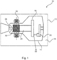
- Fig. 1 illustrates a conventional rotating anode X-ray tube 10. It comprises an external container 12 with a tube envelope 14 inside. A gap between the external container 12 and the tube envelope 14 is typically filled with an insulating fluid, such as oil.
- the tube envelope contains a rotatable anode disk 18, and a cathode 20 aligned with an outer perimeter of the rotatable anode disk 18.
- the cathode 20 emits electrons at high velocity towards the outer perimeter of the rotatable anode disk 18, and X-ray emission 22 out of the vacuum envelope occurs principally as bremsstrahlung emission.
- the rotatable anode disk 18 Only a small proportion of the high velocity electrons are converted into X-ray radiation, leaving the energy in the rest of the electron beam to be dissipated from the focal spot on the outer perimeter of the rotatable anode disk 18 as, typically, 50 kW to 100 kW of heat energy. For this reason, the rotatable anode disk 18 is rotated at frequencies as high as 200 Hz, to ensure that the target area (focal track) is not damaged by excessive heating.
- a bearing system 24 is provided between an anode support shaft inside the tube envelope 14, and an outer rotor 26.
- this is a liquid metal bearing system to enable heat conduction from the rotatable anode disk 18 out of the vacuum envelope.
- a motor subsystem comprising a stator 28 attached to the external container 12 and a rotor body 30 typically comprising a copper cylinder. In operation, energisation of the stator 28 causes the rotatable anode disk 18 to move around an axis defined by the bearing system 24.
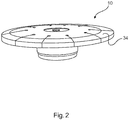
- Fig. 2 illustrates a conventional X-ray rotating anode target 32.
- the illustrated target is a segmented all-metal anode bearing a focal track region 34 which may, for example, comprise a tungsten-rhenium alloy of 1 mm thickness as its top layer.
- a thick refractory metal alloy significantly increases the cost of such a rotary anode.
- rhenium as a rough heat radiating coating means that the granular structure of the rhenium coating is disadvantageous from a thermal perspective, as the lateral heat conductivity is diminished compared with the bulk material of the anode. Furthermore, the quality and amount of X-radiation, which is typically taken off the anode at a grazing angle, is worsened through intrinsic attenuation and beam filtration.
- Fig. 3 a illustrates a schematic of a rotary anode according to a first aspect in a side cut-through view through the axis of rotation.
- a rotatable anode 40 for a rotating-anode X-ray source comprising:
- the target region comprises a multi-layer coating 46a, 46b comprising a first layer 46a of a first material deposited on a surface of the substrate 42, and a second layer 46b of a second material deposited on the surface of the first layer.
- a thickness ratio between the first and second layers of the multi-layer coating in the target region is in the range 0.5 to 2.0.
- thickness ratio between the first layer 46a and the second layer 46b is in the range 0.95 to 1.05, or in the range 0.6 to 1.5, or in the range 0.75 to 1.25.
- the total thickness of the first layer 40a and the second layer 40b is in the range 5 ⁇ m to 60 ⁇ m, in the range 20 ⁇ m to 55 ⁇ m, or in the range 30 ⁇ m to 52.5 ⁇ m.
- the target region is provided with a multi-layer coating comprising two materials which may be selected to have complimentary properties in operation.
- the first material is a material having relatively high mechanical stability at high temperature and stress compared to the second material such as rhenium, tantalum, tungsten carbide, or tungsten carbide.
- Rhenium additionally functions as a diffusion barrier between a carbon anode substrate and the tungsten layer, for example.
- the second material may, for example, be a material having a higher thermal conductivity compared to the first material, for example tungsten or iridium.
- the second material is pure tungsten, and the second layer has a thickness in the range of 5 ⁇ m to 60 ⁇ m, 10 ⁇ m to 50 ⁇ m, 15 ⁇ m to 45 ⁇ m, 20 ⁇ m to 35 ⁇ m, 22.5 ⁇ m to 27.5 ⁇ m.
- Fig. 3a illustrates an example schematic of a rotary anode according to an optional embodiment of the first aspect in a side cut-through view through the axis of rotation.
- the target region 44 is provided as a first area 48 of the rotatable anode, and a non-target region 50a, 50b comprises a second area of the rotatable anode, the first layer of the first material additionally deposited on the surface of the second area of the substrate 42.
- a microscopic layer 46a of a first material for example, rhenium
- a second microscopic layer 46b of tungsten is provided on top of the layer of the first material in the target region (focal track).
- substrate 42 is formed from carbon composite or graphite.
- the surface of the second material is smoothed by a thermal sintering process at a temperature of optionally greater than 1500°C, greater than 2000 °C, or greater than 2250 °C, or greater than 2500°C or greater than 2750 °C.
- the surface roughness of the second material in the target region may be lower than 5 ⁇ m, meaning that a further surface smoothing step (for example, performed by machining) is not required.
- the first material is provided as a layer of pure rhenium having a thickness ranging between 20 ⁇ m to 25 ⁇ m
- the second material is provided as a layer of pure tungsten having a thickness ranging between 20 ⁇ m to 25 ⁇ m.
- the rhenium has superior mechanical performance to that of tungsten, and can perform as a diffusion barrier for carbon.
- the tungsten has a superior thermal performance compared to the rhenium, and functions to spread heat more quickly to areas of the focal track that are not in the direct instantaneous path of the electron beam.
- the relative thinness of both of the rhenium and tungsten layers (when compared with the typical case of a 1mm thick rhenium layer, for example) means that tensile stresses caused by thermal expansion and contraction are minimized, compared to the use of thicker rhenium and/or tungsten layers. Furthermore, cracks appear less quickly, compared to conventional allrhenium surfaces.
- the microscopic surface of rhenium comprises many irregularities which protrude tens of ⁇ m from the substrate surface (seen, for example, in fig. 4c ).
- the use of tungsten as a second material layer enables the tungsten to "spread" around the protrusions of rhenium, improving the smoothness of the rotary anode.
- the target region 44 is provided as a first area 48 of the rotatable anode, and a non-target region 50 a, 50b comprises a second area of the rotatable anode.
- Fig. 3b illustrates a schematic side-view of a rotary anode according to an optional embodiment of the first aspect in a cut-through view through the axis of rotation.
- reference numerals are common to Fig. 3a ), where appropriate.
- the target region 44 is provided as a first area 48 of the rotatable anode, and a non-target region 50a, 50b comprises a second area of the rotatable anode, the first layer of the first material additionally deposited on the surface of the second area of the substrate 42.
- a microscopic layer 46a of a first material for example, rhenium
- a second microscopic layer 46b of tungsten is provided in the target region (focal track).
- the roughened surface of the rhenium exposed in the non-target region is a better heat radiator than the bare anode substrate.
- the target region 44 extends into the non-target region by 5%, 10%, or 15% of the width of a focal spot to provide a safety margin, such that the microscopically thin rhenium layer is not damaged by direct exposure to the electron beam.
- a rotary anode X-ray tube comprising:
- Fig. 4 illustrates a process for manufacturing a rotatable anode according to the first aspect.
- the method of manufacturing a rotatable anode comprises:
- Step a) of providing a rotatable anode substrate optionally comprises obtaining a circular carbon (carbon felt or composite) or graphite blank and placing it in a suitable chemical vapour deposition (CVD) reaction chamber.
- CVD chemical vapour deposition
- Step b) comprises the deposition, for example by chemical vapour deposition, of a first layer of a first material on the substrate blank, to generate a substrate intermediate.
- the first material is rhenium, optionally deposited to a thickness of 25 ⁇ m.
- the CVD reaction chamber is purged in preparation for subsequent step.
- CVD has been referred to above, any suitable material deposition approach maybe used in the manufacturing method.
- PLD pulsed laser deposition
- PS plasma spraying
- electroplating are provided as nonlimiting examples of other manufacturing techniques applicable in steps a) and b).
- Step c) comprises the deposition, for example by chemical vapour deposition, of a second layer of a second material on the substrate intermediate.
- the second material is tungsten, optionally deposited to a thickness of 25 ⁇ m.
- step b there are intermediate steps of masking the substrate or substrate intermediate, to ensure that the first and second materials are deposited only on a target region (focal track).
- the masking step is not applied before step b), such that a microscopic rhenium layer is provided across a substantially the whole upper surface of the anode blank.
- the step d) of sintering the rotatable anode substrate by heating it to a temperature in the range of 1500°C to 3200°C, preferably to 1800°C.
- the effect of the sintering operation is to smooth the surface of the second material.
- sintering may be performed using an electron beam (optionally, the electron beam of the X-ray tube itself, before degassing and vacuum evacuation).
- the focal track is smoothed by generating a focal spot having a temperature significantly higher than the focal spot applied during normal operation of the rotary anode.
- Step d) is effectively a "break-in process" that can be combined with the tube anode heat testing step performed by a tube anode manufacturer.
- the focal spot temperature during the break-in process enables the surface of the target region to have a low roughness.
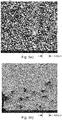
- Figs. 5a) and 5b are images of, respectively, a pure rhenium CVD coating before ( fig. 5a ) and after ( fig. 5b ) the thermal sintering process of step d). As shown, before processing, the rhenium surface is relatively rough, whereas following the thermal sintering treatment, the rhenium surface is smoother.
Priority Applications (6)
| Application Number | Priority Date | Filing Date | Title |
|---|---|---|---|
| EP17206337.2A EP3496128A1 (de) | 2017-12-11 | 2017-12-11 | Drehanode für eine röntgenquelle |
| US16/770,979 US11469071B2 (en) | 2017-12-11 | 2018-12-11 | Rotary anode for an X-ray source |
| JP2020550915A JP7309745B2 (ja) | 2017-12-11 | 2018-12-11 | X線源のための回転式アノード |
| CN201880080069.6A CN111466008A (zh) | 2017-12-11 | 2018-12-11 | 用于x射线源的旋转阳极 |
| EP18812208.9A EP3724911A1 (de) | 2017-12-11 | 2018-12-11 | Drehanode für eine röntgenquelle |
| PCT/EP2018/084350 WO2019115519A1 (en) | 2017-12-11 | 2018-12-11 | A rotary anode for an x-ray source |
Applications Claiming Priority (1)
| Application Number | Priority Date | Filing Date | Title |
|---|---|---|---|
| EP17206337.2A EP3496128A1 (de) | 2017-12-11 | 2017-12-11 | Drehanode für eine röntgenquelle |
Publications (1)
| Publication Number | Publication Date |
|---|---|
| EP3496128A1 true EP3496128A1 (de) | 2019-06-12 |
Family
ID=60661807
Family Applications (2)
| Application Number | Title | Priority Date | Filing Date |
|---|---|---|---|
| EP17206337.2A Withdrawn EP3496128A1 (de) | 2017-12-11 | 2017-12-11 | Drehanode für eine röntgenquelle |
| EP18812208.9A Pending EP3724911A1 (de) | 2017-12-11 | 2018-12-11 | Drehanode für eine röntgenquelle |
Family Applications After (1)
| Application Number | Title | Priority Date | Filing Date |
|---|---|---|---|
| EP18812208.9A Pending EP3724911A1 (de) | 2017-12-11 | 2018-12-11 | Drehanode für eine röntgenquelle |
Country Status (5)
| Country | Link |
|---|---|
| US (1) | US11469071B2 (de) |
| EP (2) | EP3496128A1 (de) |
| JP (1) | JP7309745B2 (de) |
| CN (1) | CN111466008A (de) |
| WO (1) | WO2019115519A1 (de) |
Cited By (1)
| Publication number | Priority date | Publication date | Assignee | Title |
|---|---|---|---|---|
| CN111048380A (zh) * | 2019-12-23 | 2020-04-21 | 西北核技术研究院 | 一种可旋转耐烧蚀强流二极管阳极靶 |
Families Citing this family (4)
| Publication number | Priority date | Publication date | Assignee | Title |
|---|---|---|---|---|
| WO2019236384A1 (en) | 2018-06-04 | 2019-12-12 | Sigray, Inc. | Wavelength dispersive x-ray spectrometer |
| US10658145B2 (en) | 2018-07-26 | 2020-05-19 | Sigray, Inc. | High brightness x-ray reflection source |
| CN112823280A (zh) | 2018-09-07 | 2021-05-18 | 斯格瑞公司 | 用于深度可选x射线分析的系统和方法 |
| US11152183B2 (en) | 2019-07-15 | 2021-10-19 | Sigray, Inc. | X-ray source with rotating anode at atmospheric pressure |
Citations (2)
| Publication number | Priority date | Publication date | Assignee | Title |
|---|---|---|---|---|
| US3982148A (en) | 1975-05-07 | 1976-09-21 | Ultramet | Heat radiating coating and method of manufacture thereof |
| EP0062380A1 (de) * | 1981-04-07 | 1982-10-13 | Koninklijke Philips Electronics N.V. | Verfahren zur Herstellung einer Anode für Röntgenröhre und Anode |
Family Cites Families (19)
| Publication number | Priority date | Publication date | Assignee | Title |
|---|---|---|---|---|
| US4132916A (en) * | 1977-02-16 | 1979-01-02 | General Electric Company | High thermal emittance coating for X-ray targets |
| JPS53102690A (en) * | 1977-02-18 | 1978-09-07 | Toshiba Corp | Target for x-ray tube |
| US4103198A (en) | 1977-07-05 | 1978-07-25 | Raytheon Company | Rotating anode x-ray tube |
| US4298816A (en) * | 1980-01-02 | 1981-11-03 | General Electric Company | Molybdenum substrate for high power density tungsten focal track X-ray targets |
| FR2593324B1 (fr) * | 1986-01-17 | 1988-03-25 | Thomson Cgr | Anode tournante avec graphite pour tube radiogene |
| US5148463A (en) * | 1991-11-04 | 1992-09-15 | General Electric Company | Adherent focal track structures for X-ray target anodes having diffusion barrier film therein and method of preparation thereof |
| US5577263A (en) | 1995-03-22 | 1996-11-19 | Alliedsignal Inc. | Chemical vapor deposition of fine grained rhenium on carbon based substrates |
| JP2948163B2 (ja) * | 1996-02-29 | 1999-09-13 | 株式会社東芝 | X線装置 |
| AT406205B (de) | 1997-10-30 | 2000-03-27 | Plansee Ag | Verfahren zur herstellung einer drehanoden-baueinheit |
| US5943389A (en) | 1998-03-06 | 1999-08-24 | Varian Medical Systems, Inc. | X-ray tube rotating anode |
| US6430264B1 (en) * | 2000-04-29 | 2002-08-06 | Varian Medical Systems, Inc. | Rotary anode for an x-ray tube and method of manufacture thereof |
| JP4098193B2 (ja) * | 2003-08-25 | 2008-06-11 | 株式会社東芝 | すべり軸受および回転陽極型x線管 |
| US20070207338A1 (en) | 2006-03-01 | 2007-09-06 | Plasma Processes, Inc. | X-ray target and method for manufacturing same |
| US8948344B2 (en) * | 2009-06-29 | 2015-02-03 | Koninklijke Philips N.V. | Anode disk element comprising a conductive coating |
| FR2962591B1 (fr) * | 2010-07-06 | 2017-04-14 | Acerde | Anode pour l'emission de rayons x et procede de fabrication d'une telle anode |
| AT12462U3 (de) * | 2012-01-09 | 2013-05-15 | Plansee Se | Röntgendrehanode mit zumindest anteilig radial ausgerichteter schleifstruktur |
| JP6404949B2 (ja) * | 2014-05-21 | 2018-10-17 | コーニンクレッカ フィリップス エヌ ヴェKoninklijke Philips N.V. | 流体動圧軸受、x線管、x線システム及び流体動圧軸受を製造する方法 |
| DE202014011302U1 (de) * | 2014-05-28 | 2019-02-25 | Jules Hendrix | Röntgengenerator |
| US9911570B2 (en) * | 2015-12-14 | 2018-03-06 | Varex Imaging Corporation | Antiwetting coating for liquid metal |
-
2017
- 2017-12-11 EP EP17206337.2A patent/EP3496128A1/de not_active Withdrawn
-
2018
- 2018-12-11 CN CN201880080069.6A patent/CN111466008A/zh active Pending
- 2018-12-11 WO PCT/EP2018/084350 patent/WO2019115519A1/en unknown
- 2018-12-11 JP JP2020550915A patent/JP7309745B2/ja active Active
- 2018-12-11 EP EP18812208.9A patent/EP3724911A1/de active Pending
- 2018-12-11 US US16/770,979 patent/US11469071B2/en active Active
Patent Citations (2)
| Publication number | Priority date | Publication date | Assignee | Title |
|---|---|---|---|---|
| US3982148A (en) | 1975-05-07 | 1976-09-21 | Ultramet | Heat radiating coating and method of manufacture thereof |
| EP0062380A1 (de) * | 1981-04-07 | 1982-10-13 | Koninklijke Philips Electronics N.V. | Verfahren zur Herstellung einer Anode für Röntgenröhre und Anode |
Cited By (2)
| Publication number | Priority date | Publication date | Assignee | Title |
|---|---|---|---|---|
| CN111048380A (zh) * | 2019-12-23 | 2020-04-21 | 西北核技术研究院 | 一种可旋转耐烧蚀强流二极管阳极靶 |
| CN111048380B (zh) * | 2019-12-23 | 2022-11-04 | 西北核技术研究院 | 一种可旋转耐烧蚀强流二极管阳极靶 |
Also Published As
| Publication number | Publication date |
|---|---|
| EP3724911A1 (de) | 2020-10-21 |
| CN111466008A (zh) | 2020-07-28 |
| JP2021506097A (ja) | 2021-02-18 |
| US11469071B2 (en) | 2022-10-11 |
| US20200388461A1 (en) | 2020-12-10 |
| WO2019115519A1 (en) | 2019-06-20 |
| JP7309745B2 (ja) | 2023-07-18 |
Similar Documents
| Publication | Publication Date | Title |
|---|---|---|
| US11469071B2 (en) | Rotary anode for an X-ray source | |
| JP5461400B2 (ja) | 回転陽極型の高出力x線管構成に対する陽極ディスク構造のハイブリッド設計 | |
| US6560315B1 (en) | Thin rotating plate target for X-ray tube | |
| US3795832A (en) | Target for x-ray tubes | |
| EP0300808B1 (de) | Röntgenröhre und Verfahren zur Erzeugung von Röntgenstrahlen in der Röhre | |
| US5414748A (en) | X-ray tube anode target | |
| US20110249803A1 (en) | Attachment of a high-z focal track layer to a carbon-carbon composite substrate serving as a rotary anode target | |
| WO2012169141A1 (en) | X-ray emitting target and x-ray emitting device | |
| US9715989B2 (en) | Multilayer X-ray source target with high thermal conductivity | |
| EP3667695A1 (de) | Mehrschichtiges röntgenstrahlenquellentarget mit spannungsentlastungsschicht | |
| EP1449232A2 (de) | Hitzeschild in einer drehanoden-röntgenröhre | |
| US20210350997A1 (en) | X-ray source target | |
| EP0305547B1 (de) | Treffplatte für eine röntgenröhre, verfahren zu ihrer herstellung und röntgenröhre | |
| EP0756308B1 (de) | Röntgenröhre und anodentarget dafür | |
| EP2652767B1 (de) | Anodentellerelement mit feuerfester zwischenschicht und vps-brennbahn | |
| KR101824135B1 (ko) | 열적 손상을 방지하는 양극 회전형 엑스선관 및 엑스선관 장치 | |
| WO2012169143A1 (en) | X-ray emitting target and x-ray emitting device | |
| US10438768B2 (en) | X-ray systems and methods including X-ray anodes with gradient profiles | |
| US5349626A (en) | X-ray tube anode target | |
| EP2494575B1 (de) | Röntgenstrahlengenerator, röntgensystem und gebrauch des röntgenstrahlgenerators | |
| US10490385B2 (en) | X-ray systems and methods including X-ray anodes |
Legal Events
| Date | Code | Title | Description |
|---|---|---|---|
| PUAI | Public reference made under article 153(3) epc to a published international application that has entered the european phase |
Free format text: ORIGINAL CODE: 0009012 |
|
| AK | Designated contracting states |
Kind code of ref document: A1 Designated state(s): AL AT BE BG CH CY CZ DE DK EE ES FI FR GB GR HR HU IE IS IT LI LT LU LV MC MK MT NL NO PL PT RO RS SE SI SK SM TR |
|
| AX | Request for extension of the european patent |
Extension state: BA ME |
|
| RAP1 | Party data changed (applicant data changed or rights of an application transferred) |
Owner name: KONINKLIJKE PHILIPS N.V. |
|
| STAA | Information on the status of an ep patent application or granted ep patent |
Free format text: STATUS: THE APPLICATION IS DEEMED TO BE WITHDRAWN |
|
| 18D | Application deemed to be withdrawn |
Effective date: 20191213 |